Article

Effects of Tooth Modification in the Involute Helical Gear Form-Grinding Process on Loaded Transmission Character with Consideration of Tooth Axial Inclination Error

1
School of Mechanical Engineering, University of Shanghai for Science and Technology, Shanghai 200093, China
2
School of Mechanical and Automotive Engineering, Shanghai University of Engineering Science, Shanghai 201620, China
*
Author to whom correspondence should be addressed.
Machines 2023, 11(2), 305; https://doi.org/10.3390/machines11020305
Submission received: 18 January 2023 / Revised: 11 February 2023 / Accepted: 16 February 2023 / Published: 17 February 2023

Abstract

:
Due to the existence of machining and installation errors, axis parallelism error of gear pairs occurs, which causes eccentric load and mesh in-out impact, thus weakening loaded transmission character. To solve this problem, the axis parallelism error of gear pairs was equated with tooth axial inclination error based on the gear-meshing principle. On this basis, we established the tooth modification model with tooth axial inclination error as the variable according to involute helical gear form-grinding process. Then, the degradation of loaded transmission character caused by axis parallelism error of gear pairs was quantitatively analyzed. The gear grinding, gear measuring, and gearbox vibration measuring were, respectively, performed on high-precision CNC horizontal gear form-grinding machine tool L300G, Gleason 350 GMS, and JWY-II multifunctional gearbox loading test bench. The results show that the proposed method can effectively reduce eccentric load and mesh in-out impact and significantly improve loaded transmission character. Therefore, it can provide a theoretical and experimental basis for the research of high-performance gear-grinding technology of gear-grinder machines.

1. Introduction

As the core mechanical transmission part, the gear is the basis of machinery [1]. However, due to the existence of machining and installation errors, it will result in axis parallelism error of gear pairs [2], which causes eccentric load and mesh in-out impact, and seriously weaken loaded transmission character [3,4,5,6]. Among the fruitful research, tooth modification for form grinding can effectively improve loaded transmission character [7,8,9,10]. Shen et al. [11] studied the tooth modification mode for involute spur gear form grinding; Wang et al. [12] obtained a tooth surface modified error model of involute helical gear by iteratively solving contact line equation; Lee et al. and Shih et al. [13,14] proposed a tooth modification model with higher-order polynomials to improve loaded transmission character.
The key to the technology of tooth modification for form grinding is the calculation of the contact line and cross-sectional profile of the grinding wheel. Based on the gear-meshing principle, Xia et al. [15] deduced the contact line equation between the gear work-piece and grinding wheel and obtained a cross-sectional profile of the grinding wheel for involute helical gear form grinding; based on weighted-sum-of-squares (WSS) method, Guo et al. [16,17] studied the influence of gear parameters and installation parameters on the contact line and proposed a contact line optimization model; Ding et al. [18] proposed the optimization model of the contact line and a cross-sectional profile of the grinding wheel by changing the installation parameters; Fang et al. [19] optimized grinding wheel posture and path by minimizing the error square sum of the modified tooth surface and proposed a contact line optimization model; based on neural networks, Wang et al. [20] realized contact line optimization for involute helical gear form grinding.
The influence of tooth modification for form grinding on loaded transmission character has been studied. Abroad, Seol et al. [21] studied the relationship among tooth axial modification amount, tooth surface contact pattern, and gearbox transmission error and developed a dynamic load calculation program of the involute helical gearbox with tooth axial modification; Zhang et al. [22] studied the influence of tooth modification and tooth contact deformation on gearbox transmission error; Du et al. [23] proposed a tooth axial modification method with tooth contact deformation; Imrek et al. [24] studied the relationship between tooth axial modification and tooth surface contact stress. At home, influence of tooth modification for form grinding on loaded transmission character is also studied [25,26], and Song et al. [27]’s tooth modification is the common method.
The above studies are of great significance for improving loaded transmission character. However, there is a lack of relevant research with consideration of the reduction of “tooth profile distortion” and “tooth axial twist” in the involute helical gear form-grinding process and tooth modification, including tooth axial modification and tooth profile modification, to solve the axis parallelism error problem of gear pairs. A novel approach based on the gear-meshing principle is proposed, which equates the axis parallelism error of gear pairs with tooth axial inclination error. On this basis, we established the tooth modification model with tooth axial inclination error as the variable according to the involute helical gear form-grinding process. Then, the gear grinding, gear measuring, and gearbox vibration measuring were, respectively, performed on the high-precision CNC horizontal gear form-grinding machine tool L300G, Gleason 350 GMS, and JWY-II multifunctional gearbox loading test bench. The objective of this paper is to quantitatively analyze the degradation of loaded transmission character caused by the axis parallelism error of gear pairs.

2. Tooth Modification Model Based on Tooth Axial Inclination Error

2.1. Axis Parallelism Error of Gear Pairs

As shown in Figure 1a, when the measured axis line 1 deviates from the theoretical axis line 2, GB/Z 18620.3-2008 (Cylindrical gears—Code of inspection practice—Part 3: Recommendations relative to gear blanks, shaft center distance and parallelism of axes) stipulates that the axis parallelism error of gear pairs within bearing holes span L in horizontal plane (H) is Δ f   δ , and the axis parallelism error of gear pairs within bearing holes span L in vertical plane (V) is Δ f   β . In Figure 1a, based on the gear-meshing principle, the axis parallelism error of gear pairs within tooth width b can be equated with the tooth axial inclination error λ . As shown in Figure 1a,b, points A, B, and C can be projected into coordinate system XOY to obtain points O 3 ,   O 1 , and O 2 . Based on the geometric relationship and gear-meshing principle, the axis parallelism error of gear pairs within tooth width b can be equated with the tooth axial inclination error λ 2 along the theoretical meshing line and tooth axial inclination error λ 1 perpendicular to the theoretical meshing line. If gear pairs have a tooth axial inclination error λ 2 , it will cause eccentric load; if gear pairs have a tooth axial inclination error λ 1 , it will cause mesh in-out impact.
In Figure 1b, the axis parallelism error at point O 3 ( A ) can be recorded as Δ f   δ and Δ f   β . The axis parallelism error at point O 1 ( B ) can be recorded as Δ f   δ 1 and Δ f   β 1 , which are expressed in Equations (1) and (2); the axis parallelism error at point O 2 ( C ) can be recorded as Δ f   δ 2 and Δ f   β 2 , which are expressed in Equations (3) and (4).
Δ f   δ 1 = O C ¯ + b L Δ f   δ
Δ f   β 1 = O C ¯ + b L Δ f   β
Δ f   δ 2 = O C ¯ L Δ f   δ
Δ f   β 2 = O C ¯ L Δ f   β
where L is the bearing holes span; b is the tooth width.
In Figure 1b, the angle between the theoretical center distance and actual center distance β i is expressed as Equation (5).
β i = arcsin Δ f   β i a i
where i = 1 , 2 correspond, respectively, to points O 1 ( B ) and O 2 ( C ) ; a i is the actual center distance of gear pairs, expressed as Equation (6).
a i = Δ f   β i 2 + ( | Δ f   δ i | + a ) 2
where i = 1 , 2 correspond, respectively, to points O 1 ( B ) and O 2 ( C ) ; a is the theoretical center distance shown in Figure 1a.
Based on the gear-meshing principle, the relationship of the center distance and meshing angle of gear pairs can be expressed as Equation (7).
α i = arccos a · cos α a i = arccos a · cos α Δ f   β i 2 + ( | Δ f   δ i | + a ) 2
where i = 1 , 2 correspond, respectively, to points O 1 ( B ) and O 2 ( C ) ; α is the theoretical meshing angle of gear pairs, α i is the actual meshing angle of gear pairs.
In Figure 1b, according to geometric relationship, the tooth axial inclination error λ 2 can be expressed as Equation (8).
λ 2 = | sin ( 2 + β 2 1 β 1 ) + cos ( 1 + β 1 ) Δ δ sin ( 1 + β 1 ) Δ β |
where
1 = 90 ° α 1 ; 2 = 90 ° α 2 ; Δ δ = Δ f   δ 2 Δ f   δ 1 ; Δ β = Δ f   β 1 Δ f   β 2
The tooth axial inclination error λ 1 can be expressed as Equation (9).
λ 1 = λ 2 λ 2 2 = [ ( Δ f   δ 2 Δ f   δ 1 ) 2 + ( Δ f   β 1 Δ f   β 2 ) 2 ] λ 2 2

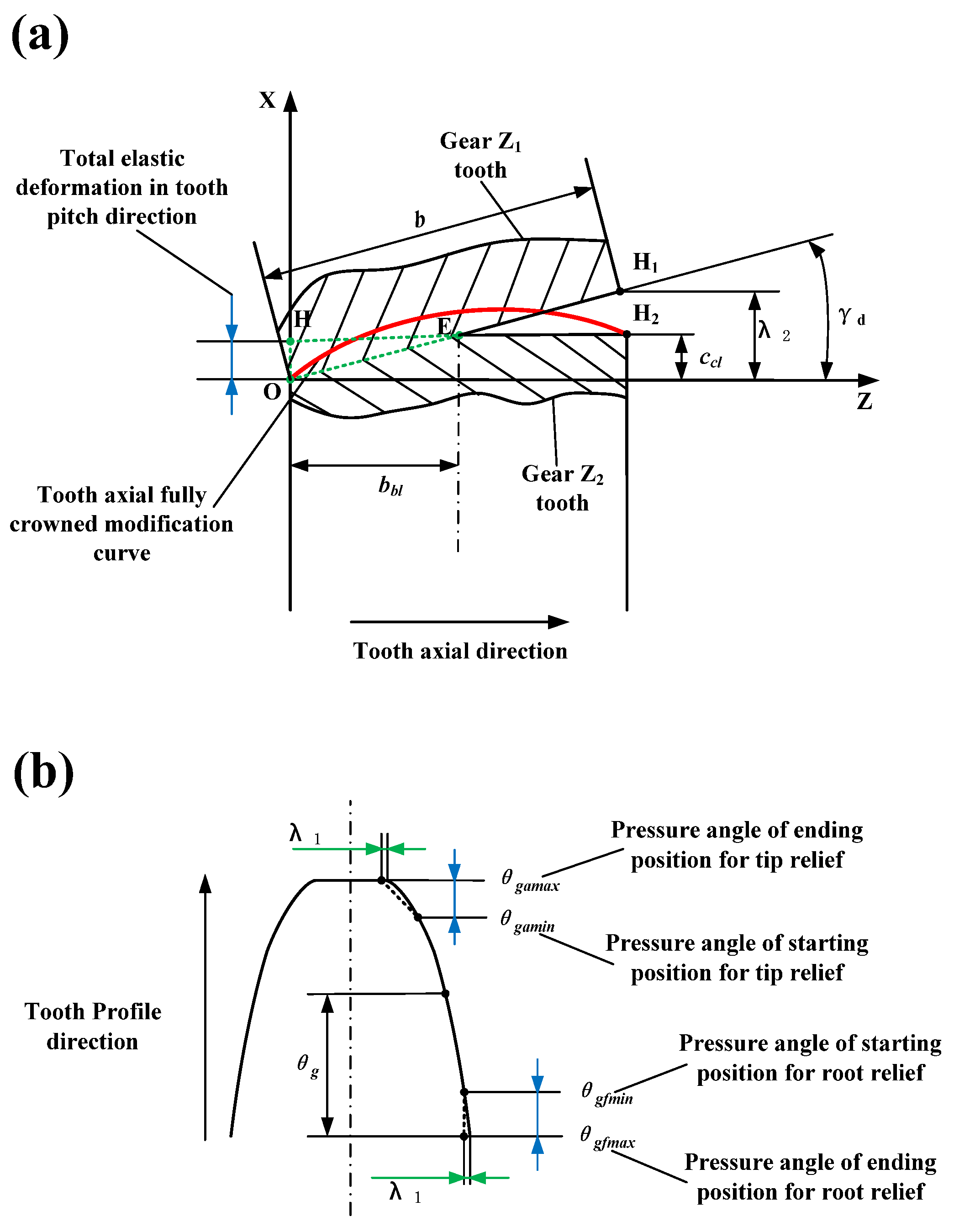
2.2. Tooth Modification Model Based on Tooth Axial Inclination Error

Research shows that tooth modification can effectively improve loaded transmission character, where the tooth axial modification can decrease eccentric load, and tooth profile modification can reduce mesh in-out impact. The tooth axial modification method includes spiral angle modification, crowned modification, and curve surface modification. The tooth axial fully crowned modification is especially suitable for solving the eccentric load problem. The tooth profile modification method includes tip relief, root relief, tooth angle correction, and curve surface modification. The tooth profile tip relief and root relief are especially suitable for solving the mesh in-out impact problem.
As shown in Figure 2a, due to the existence of the axis parallelism error of gear pairs (tooth axial inclination error), the working tooth surfaces will press into each other, which is shown as the green, dotted triangle area during loaded transmission. Song et al. [27] believed that the total elastic deformation of working tooth surface in tooth pitch direction can be taken as the tooth axial fully crowned modification amount, which will decrease eccentric load and improve loaded transmission character. Thus, the model of tooth axial fully crowned modification with tooth axial inclination error λ 2 as the variable is established to solve the eccentric load problem. The equivalent tooth axial inclination angle of the tooth axial inclination error λ 2 is equal to γ d ; the total elastic deformation in tooth pitch direction is O H ¯ , the tooth axial fully crowned modification amount is C c 1 , and C c 1 is equal to O H ¯ . Then, the curve O H 2 can be drawn as the tooth axial fully crowned modification curve, and C c 1 can be expressed as Equation (10).
C c 1 = O H ¯ = b b l t a n ( γ d ) = b b l b λ 2
where b b l is the total elastic deformation in the tooth axial direction, and b b l = H E ¯ ; if 1 b b l b 0.5 , let b b l b = 0.5 ; if 0.5 > b b l b > 0 , let b b l b = 0.25 ; b is the tooth width.
The tooth axial fully crowned modification curve equation can be expressed as Equation (11).
X ( Z , λ 2 ) = 4 C c l b 2 Z 2 + 4 C c l + λ 2 b Z
As shown in Figure 2b, Sun et al. [28] believed that tooth profile modification will reduce mesh in-out impact and improve loaded transmission character, so the model of tooth profile tip relief and root relief with tooth axial inclination error λ 1 as the variable is established to solve the mesh in-out impact problem. The modification amount of both tooth profile tip relief and root relief is λ 1 , and the pressure angle of corresponding point for tooth profile tip relief and root relief is θ g ; then, the tooth profile tip relief and root relief curve equation can be expressed as Equation (12) [29].
S ( θ g , λ 1 ) = { ( θ g θ g a m a x ) λ 1 ( θ g a m a x θ g a m i n ) 2 , θ g a m i n < θ g θ g a m a x 0 , θ g f m i n θ g θ g a m i n ( θ g θ g f m a x ) λ 1 ( θ g f m a x θ g f m i n ) 2 , θ g f m a x θ g < θ g f m i n
where θ g a m i n is the pressure angle of the starting position for tip relief; θ g a m a x is the pressure angle of the ending position for tip relief; θ g f m i n is the pressure angle of the starting position for root relief; θ g f m a x is the pressure angle of the ending position for root relief.

3. Involute Helical Gear Form Grinding with Tooth Modification

3.1. Tooth Surface Equation of Involute helical Gear with Tooth Modification

As shown in Figure 3, the intersection point O g of the involute helical gear tooth surface middle section and gear axis line is set as the origin of the coordinate system ( O g X g Y g Z g ) . Axis Y g passes through tooth surface node point M , and axis Z g coincides with gear axis line; then, the tooth surface equation of involute helical gear with tooth modification can be expressed as Equations (13)–(18) [30,31].
R g ( θ g , φ g ) = ( X g ( θ g , φ g ) , Y g ( θ g , φ g ) , Z g ( θ g , φ g ) )
{ X g ( θ g , φ g ) = q s g ( θ g , φ g ) cos ( α t + θ g + φ g ) + r b g sin ( α t + θ g + φ g ) Y g ( θ g , φ g ) = q s g ( θ g , φ g ) sin ( α t + θ g + φ g ) + r b g cos ( α t + θ g + φ g ) Z g ( θ g , φ g ) = P g φ g / 2 π
q s g ( θ g , φ g ) = q 0 g + r b g θ g + S ( θ g ) + X ( φ g )
q 0 g = r b g tan α t
S ( θ g ) = S ( θ g , λ 1 )
X ( φ g ) = X ( φ g , λ 2 ) = X ( Z g , λ 2 )
where θ g is the pressure angle of corresponding point for tooth profile tip relief and root relief; α t is the gear end face pitch circle pressure angle; φ g is the rotation angle of gear end face section, and π b P g φ g π b P g , b is the tooth width, and P g is the helix parameter pitch of involute gear helical surface; r b g is the radius of gear base circle; S ( θ g ) is the tooth profile tip relief and root relief curve equation; X ( φ g ) is the tooth axial fully crowned modification curve equation

3.2. Involute Helical Gear Form-Grinding Process with Tooth Modification

As shown in Figure 4, in order to accurately control the relative motion of the involute helical gear and grinding wheel for the form-grinding process with tooth modification, the coordinate system S g ( O g X g Y g Z g ) needs to be established on an involute helical gear where the Z g -axis coincides with the gear axis line; the coordinate system S w ( O w X w Y w Z w ) needs to be established on a grinding wheel where the Z w -axis coincides with the grinding wheel axis line. In Figure 4, A is the shortest distance between the Z g -axis and Z w -axis along X w -direction, which is called center distance; Σ is the angle between the Z g -axis and Z w -axis, which is called the grinding wheel mounting angle. The coordinate transformation relationship of points between the involute helical gear coordinate system S g and grinding wheel coordinate system S w can be expressed as Equation (19).
{ X w = X g + A Y w = Y g cos Σ Z g sin Σ Z w = Y g sin Σ + Z g cos Σ
The existing form-grinding methods are mainly divided into single-sided grinding and double-sided grinding [32]. In single-sided grinding, the left and right tooth surfaces in the tooth groove are ground separately; in double-sided grinding, the left and right tooth surfaces in the tooth groove are ground at the same time. During involute helical gear form grinding, the involute helical gear surface and grinding wheel surface are in tangent contact along a spatial curve, which is called the three-dimensional contact line, as shown in Figure 4. The three-dimensional contact line can be projected as a two-dimensional cross-sectional profile of the grinding wheel, and the contact line for single-sided grinding is half that for double-sided grinding, but its curve shape is consistent. In Figure 4, the curve shape of the three-dimensional contact line in the tooth groove is mainly determined by the parameters A and Σ , which need to meet the following two contact conditions: (1) tangent contact is required between the involute helical gear surface and grinding wheel surface so as to complete form grinding; (2) there will be no interference between the involute helical gear surface and grinding wheel surface so as to avoid damage of the grinding wheel or over-grinding of involute helical gear. The coordinates of the contact point between the involute helical gear surface and grinding wheel surface is N g ( X g N , Y g N , Z g N ) , and if the involute helical gear surface is in tangent contact with the grinding wheel surface, it needs to meet the contact condition equation expressed as Equation (20).
f ( A , Σ ) = Z g N n X + A n Y cot Σ + ( A X g N + P g cot Σ ) n Z = 0
where n X , n Y , and   n Z are the directional components of the normal vector of point N g .
The Equation (20) is coupled to Equations (13)–(18) and transferred to the grinding wheel coordinate system S w ( O w X w Y w Z w ) , and the Equation (21) can be expressed as below.
{ f ( A , Σ ) = 0 X w N = X g N A Y w N = Y g N cos Σ + Z g N sin Σ Z w N = Y g N sin Σ + Z g N cos Σ
Since the cross-sectional profile of a grinding wheel is a curve intercepted by the Y g = 0 plane, the two-dimensional cross-sectional profile of the grinding wheel equation can be expressed as Equation (22).
{ f ( A , Σ ) = 0 Z w N = Y g N sin Σ + Z g N cos Σ R = X w N 2 + Y w N 2 = ( X g N A ) 2 + ( Y g N cos Σ + Z g N sin Σ ) 2
The curvature interference method is taken to check the interference between the involute helical gear surface and grinding wheel surface. The point N g of the involute helical gear coordinate system can be converted as point N w of the grinding wheel coordinate system by Equation (19), and the grinding radius of the grinding wheel surface at point N g ( N w ) can be expressed as Equation (23).
R N = X w N 2 + Y w N 2
The curvature radius of the involute helical gear surface at point N g ( N w ) can be expressed as Equation (24).
ρ N = [ 1 + ( d X w N d Y w N ) 3 2 / ( d 2 X w N d Y w N 2 ) ]
R N < | ρ N |
When using the external contact method to grind the involute helical gear, as long as the grinding radius of the grinding wheel surface at point N g ( N w ) is less than the absolute value of the curvature radius of the involute helical gear surface at point N g ( N w ) , it is assumed that no curvature interference occurs at point N g ( N w ) . Due to the constraints of the above two contact conditions, the grinding wheel mounting angle Σ must be taken within a certain range, which limits the cross-sectional profile of the grinding wheel. The corresponding design and calculation of the cross-sectional profile of the grinding wheel is the common tooth profile modification method. After obtaining a cross-sectional profile of a grinding wheel for tooth profile modification, in order to accurately control the relative motion of the involute helical gear and grinding wheel, besides the conventional spiral motion for tooth profile modification, the additional motion for tooth axial modifications that can be applied to single-sided grinding are gear angle compensation Δ θ , axial movement of grinding wheel Δ Z W , and center distance change Δ A ; the additional motion for tooth axial modification that can be applied to double-sided grinding is center distance change Δ A .
The corresponding design and calculation of parameter A along the involute helical gear tooth axial direction is the common tooth axial modification method. With a cross-sectional profile of the grinding wheel for tooth profile modification, the changing rate of A along the involute helical gear tooth axial direction is Δ A ( ξ ) . When grinding, as long as the Δ A ( ξ ) meets condition equation expressed as Equation (26), the tooth axial modification can be realized.
Δ A ( ξ ) = δ ( | ξ | | Z 0 | ) cos β b g / b sin α n = C c l cos β b g / b sin α n
where:   ξ is the axial motion parameter of the grinding wheel along the gear axis;   Z 0 is the axis Z g coordinate of the starting point for tooth axial fully crowned modification; δ ( | ξ | | Z 0 | ) = C c l is the tooth axial fully crowned modification amount; β b g is the helix angle of base circle; b is the tooth width; α n is the normal pressure angle of the gear.

3.3. Calculation of Cross-Sectional Profile of Grinding Wheel

According to Equation (22), the two-dimensional cross-sectional profile of a grinding wheel can be determined with parameters A and Σ . The parameter A is determined by grinding wheel radius R W and the involute helical gear base circle radius r b g as long as the gear’s basic parameters are determined, the r b g is a constant value, and A is only determined with R W , so the cross-sectional profile of a grinding wheel is jointly determined by R W and Σ . During form grinding, the grinding wheel with high wear resistance is selected, and the grinding wheel profile dressing error is set as zero; the grinding wheel wear deformation is zero. Then, the grinding wheel radius R W is a constant value, so Σ is the only variable that determines the two-dimensional cross-sectional profile of the grinding wheel. Taking the involute helical gear double-sided form grinding as an example, according to Equations (20) and (25), the Σ of double-sided form grinding for the involute helical gear Z 1 shown in Table 1 can be calculated. The value range of Σ is 64.6708°~65.4526°, and the curvature interference checking result is qualified. According to Equation (22), the two-dimensional cross-sectional profile of the grinding wheel for double-sided form grinding of the standard involute helical gear Z 1 shown in Table 1 can be calculated, and the result is shown in Figure 5.

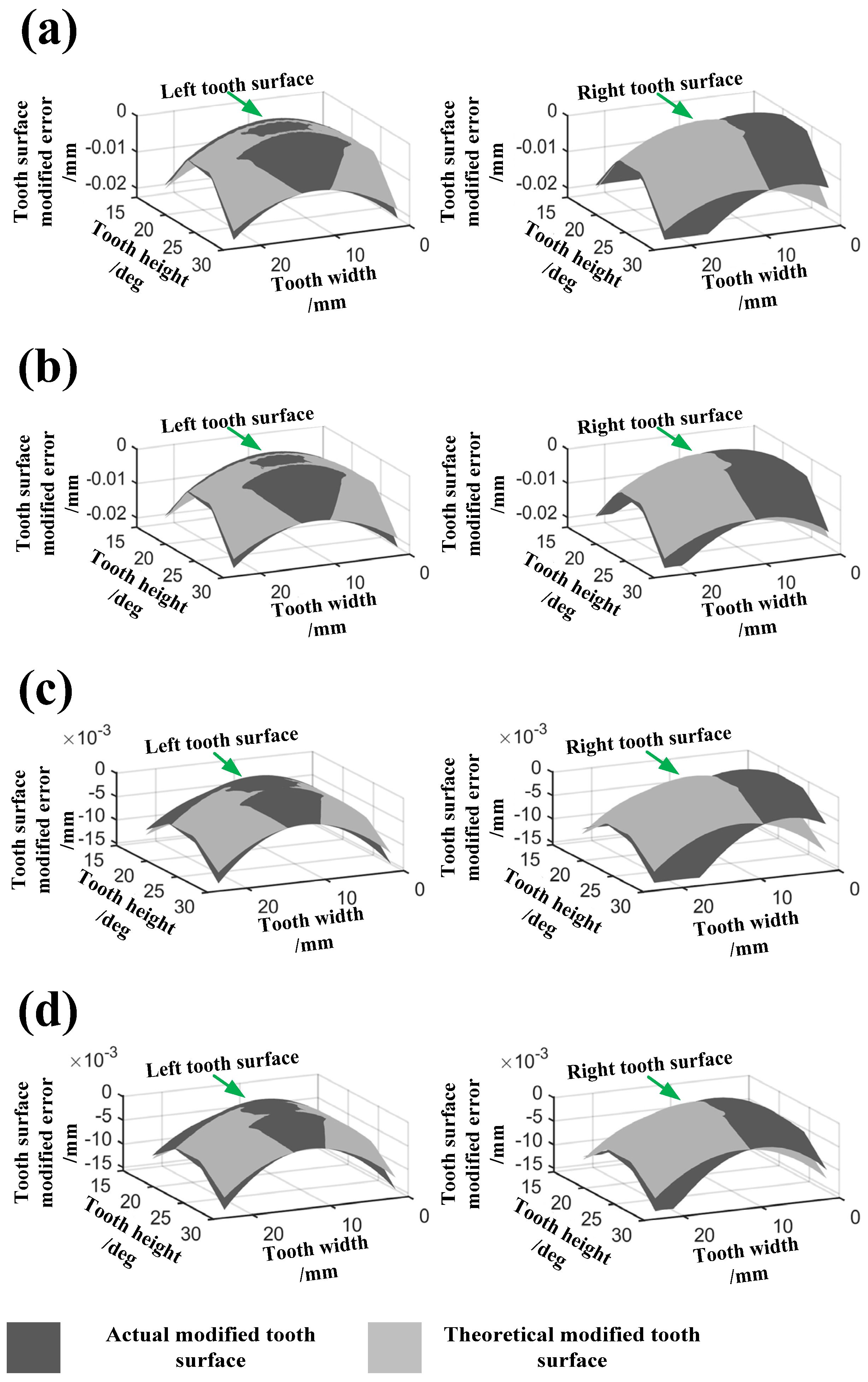
3.4. Tooth Surface Modified Error of Involute Helical Gear with Different Tooth Modification Parameters

As shown in Figure 6, the span of the bearing holes is L = 160   mm , the diameter of the gear shaft is 60   mm , and the fit tolerance of the gear shaft and bearing hole is Φ 60   H 8 / d 8 . According to Section 2, the tooth axial inclination error range can be calculated as λ = ± 14   μ m , which can be equated to tooth axial inclination error λ 2 = ± 13   μ m and tooth axial inclination error λ 1 = ± 5.2   μ m . In order to study the loaded transmission character of a gear with tooth modification, the parameters of tooth profile tip relief, tooth profile root relief, and tooth axial fully crowned modification of the involute helical right-hand gear Z 1 shown in Table 1 can be calculated, which will not be repeated, and results are shown in Table 2. Tip relief and root relief are selected for tooth profile modification; the pressure angle of the starting position for root relief is θ g f m i n = 19.7431 ° , the pressure angle of the ending position for root relief is θ g f m a x = 15.7431 ° , the pressure angle of the starting position for tip relief is θ g a m i n = 23.4655 ° , and the pressure angle of the ending position for tip relief is θ g a m a x = 27.4655 ° . Fully crowned modification is selected for tooth axial modification; the grinding wheel mounting angle is Σ = 65.3284 ° before optimization and Σ = 64.8947 ° after optimization, where the neural network method in ref. [20] is adopted to optimize Σ , which will not be repeated. Then, compared with the theoretical modified tooth surface, the tooth surface modified error of the involute helical right-hand gear Z 1 for double-sided form grinding with different modification parameters can be obtained; results are shown in Figure 7.
By comparing and analyzing the left and right tooth surface modified errors of Figure 7a, the results show that the process of the involute helical right-hand gear Z 1 for double-sided form grinding with tooth profile tip relief, tooth profile root relief, and tooth axial fully crowned modification can be realized significantly. However, there is a slight under-modifying at the left tooth root and a slight over-modifying at the left tooth tip, so there is “tooth profile distortion” on the left tooth surface; by comparing and analyzing the left tooth surface modified errors of Figure 7a,b, the results show that the “tooth profile distortion” is not sensitive to the change of Σ , and the same law can also be found by comparing and analyzing the left tooth surface modified errors of Figure 7c,d; then, the left tooth surface modified errors of Figure 7a,b and Figure 7c,d are compared and analyzed, and the results show that the “tooth profile distortion” of modification II ( Σ = 64.8947 ° after optimization) is reduced significantly, where the tooth profile modification rate is about 98.6%, which will weaken the mesh in-out impact of the gear pairs and effectively improve loaded transmission character. Moreover, there is a large error at the right tooth surface, and the peak value position of tooth axial fully crowned modification is moved, which is called “tooth axial twist”; when the involute helical right-hand gear is machined for double-sided form grinding, where the left tooth surface in the tooth groove contacts the grinding wheel first, but the right tooth surface in the tooth groove contacts the grinding wheel later, the result is “tooth axial twist”, and an unavoidable principle error between the modified gear tooth surface and standard gear tooth surface occurs; accordingly, the right tooth surface modified errors of Figure 7a,b and Figure 7c,d were compared and analyzed, and results show that the “tooth axial twist” of modification II ( Σ = 64.8947 ° after optimization) is reduced significantly, where the tooth axial modification rate is about 95.7%, which will reduce the eccentric load of the gear pairs and effectively improve loaded transmission character.

4. Finite Element Simulation of Involute Helical Gearbox with Tooth Modification

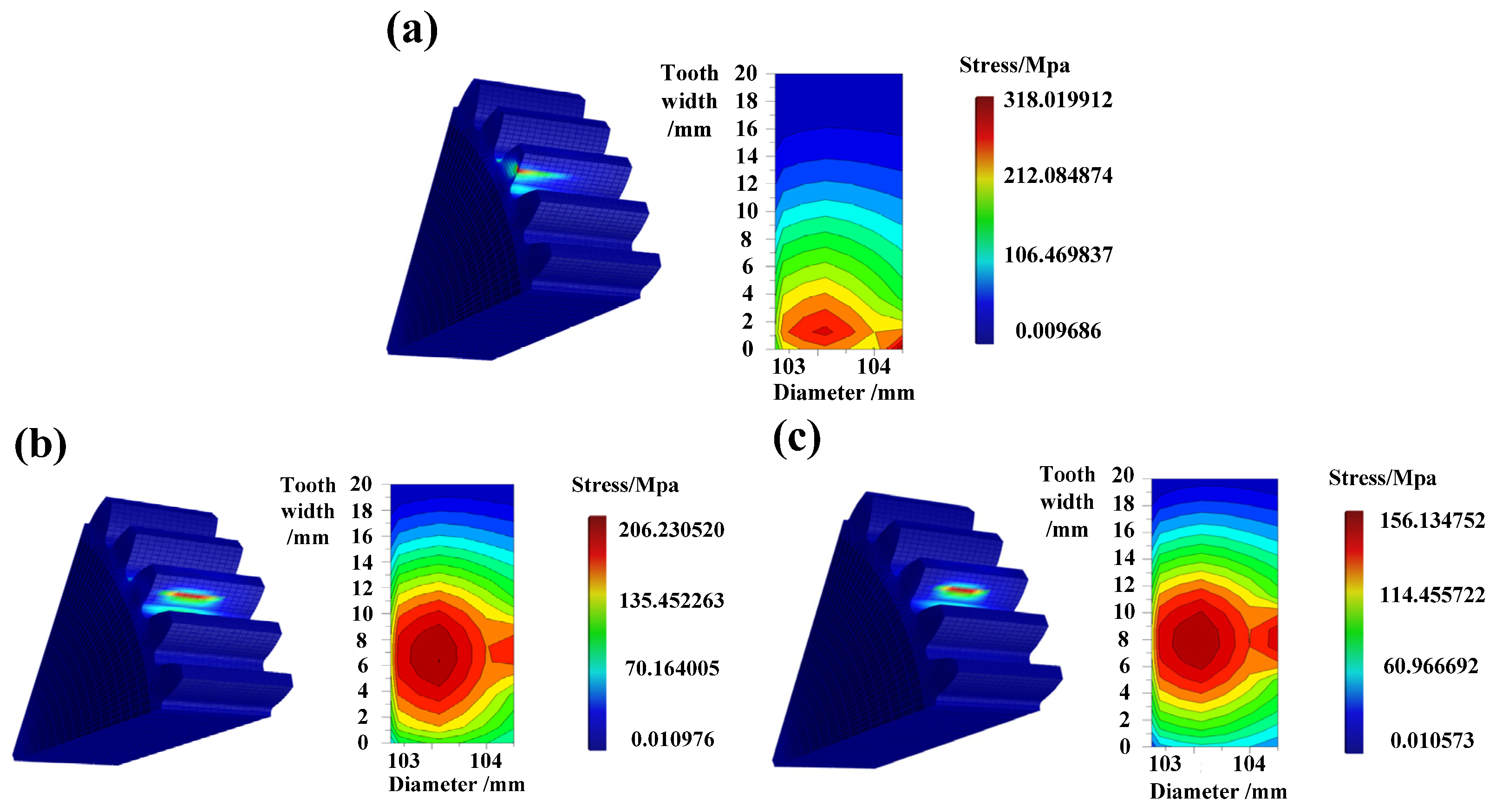
4.1. Influence of Tooth Modification on Tooth Surface Contact Stress

In order to obtain accurate simulation results, the involute helical gearbox (right-hand gear Z 1 and left-hand gear Z 2 ) with tooth axial inclination error λ = 14   μ m was simulated and analyzed by using the professional software RomaxDesigner. During the finite element simulation of the involute helical gearbox with different tooth modification parameters (without modification, modification II and Σ = 65.3284 ° before optimization, modification II and Σ = 64.8947 ° after optimization), the error-related bearing is zero, the error-related oil lubricating is zero, the thermal error of the machine tool is zero, and the geometric error of the machine tool is zero; the input shaft speed is 800 rpm, and the output shaft torque is 50 N·m. After simulation, the contact stress of the tooth surface at the reference circle of the involute helical right-hand gear Z 1 is extracted, and results are shown in Figure 8.
Results show that when the gear Z 1 is without modification, eccentric load is obvious, and the maximum contact stress reaches 318 MPa; when the gear Z 1 is modified with modification II ( Σ = 65.3284 ° before optimization), eccentric load is weakened, and the maximum contact stress is reduced to 206 MPa compared with unmodified gear, which is lower by 35.2%; when the gear Z 1 is modified with modification II ( Σ = 64.8947 ° after optimization), eccentric load is significantly weakened, and the maximum contact stress is reduced to 156 MPa compared with unmodified gear, which is lower by 50.9%.

4.2. Influence of Tooth Modification on Gearbox Transmission Error

For the involute helical gearbox with different tooth modification parameters, the influence of tooth modification on the gearbox transmission error was also simulated and analyzed by using the professional software RomaxDesigner, where the analysis conditions and parameters are consistent with Section 4.1. After operation, the gearbox transmission error with different tooth modification parameters is extracted, and results are shown in Figure 9.
The results show that when gear Z 1 is unmodified, the gearbox transmission error amplitude is about 2.55 μm; when gear Z 1 is modified with modification II ( Σ = 65.3284 ° before optimization), the gearbox transmission error amplitude is about 2.38 μm; when gear Z 1 is modified with modification II ( Σ = 64.8947 ° after optimization), the gearbox transmission error amplitude is about 2.08 μm. Compared with gear Z 1 without modification, the gearbox transmission error amplitude decreases by 6.7% in modification II ( Σ = 65.3284 ° before optimization) and 18.4% in modification II ( Σ = 64.8947 ° after optimization).

5. Experimental Verification

5.1. Static Accuracy Measuring Experiment of Machine Tools

Figure 10a shows the high-precision CNC horizontal gear form-grinding machine tool L300G, Figure 10c shows the Gleason 350 GMS gear measurement center, and the JWY-II multifunctional gearbox loading test bench will be introduced in Section 5.3. They all have an isolated vibration foundation that meets engineering manufacturing requirements, and the working laboratory is a controllable constant temperature chamber (temperature: 20 °C, humidity: 50%). Therefore, the influence of machine tool geometric error, machine tool vibration error, and machine tool thermal error on the experimental results was not studied. The machine tool static accuracy measuring experiments were carried out with cylindrical standard measuring rod and dial indicator. The circular run-out of the spindle is equal to or less than 1   μ m ; the circular run-out of the measuring rod is equal to or less than 1   μ m ; the parallelism of the measuring rod is equal to or less than 1   μ m . The results show that the static accuracy of L300G, Gleason 350 GMS, and JWY-II multifunctional gear loading test bench reach micron level, which provides an accuracy guarantee for grinding experiments, measuring experiments, and gearbox vibration measuring experiments.

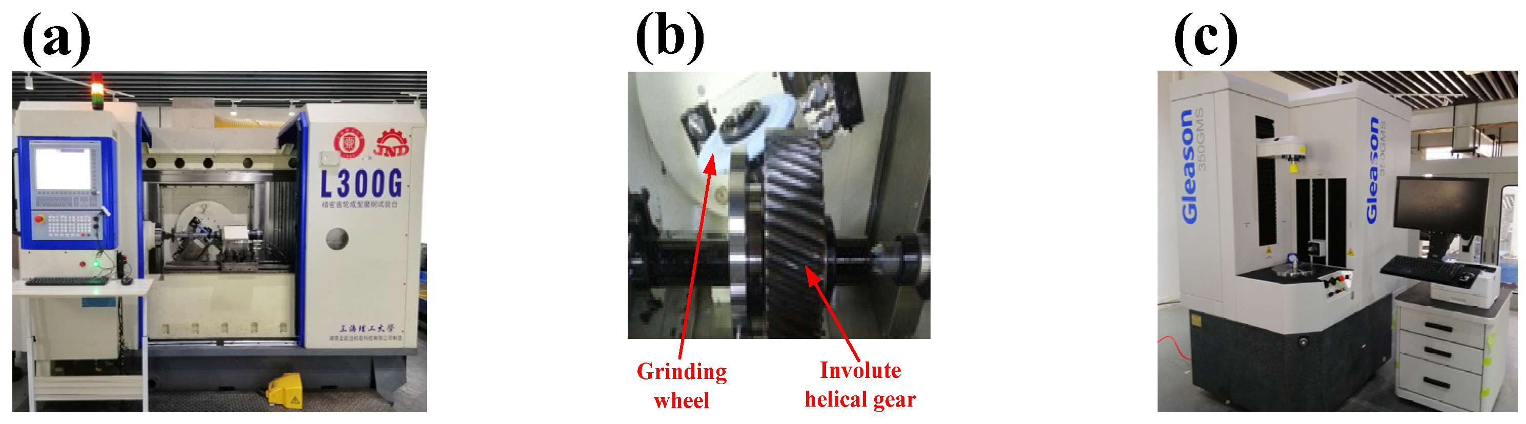
5.2. Grinding and Measuring Experiment of Involute Helical Gear with Different Tooth Modification Parameters

In order to verify the correctness of the mathematical model described in Section 2 and Section 3, the grinding experiment of the involute helical right-hand gear Z 1 for double-sided form grinding with tooth modification was carried out by using gear grinder L300G, where the grinding wheel with high wear resistance was selected, the grinding wheel profile dressing error was set as zero, the grinding wheel wear deformation was set as zero, the thermal error of the machine tool was set as zero, and the geometric error of the machine tool was set as zero. As shown in Figure 10b, the circular run-out of involute helical gear Z 1 shaft is equal to or less than 1   μ m , which will provide grinding accuracy for the grinding experiment. The grinding experiments of gear Z 1 for double-sided form grinding with different tooth modification parameters (modification II and Σ = 65.3284 ° before optimization, modification II and Σ = 64.8947 ° after optimization) were, respectively, carried out, and the tooth surface measuring experiments of modified gear Z 1 were carried out with Gleason 350 GMS gear measurement center. The results are shown in Figure 11.
In Figure 11, the Gleason measuring accuracies of the involute helical right-hand gear Z 1 for double-sided form grinding with modification II ( Σ = 65.3284 ° before optimization) and modification II ( Σ = 64.8947 ° after optimization) are, respectively, at level 4. Compared with modification II ( Σ = 65.3284 ° before optimization), the “tooth profile distortion” and “tooth axial twist” of modification II ( Σ = 64.8947 ° after optimization) are effectively reduced, and the offset of “tooth profile distortion” and “tooth axial twist” are lower by 31.6% and 31.7%, respectively; furthermore, tooth modification II ( Σ = 64.8947 ° after optimization) is significantly realized, and the tooth modification rates of the tooth profile and tooth axial are about 97.6% and 94.7%, respectively, which is almost consistent with the tooth modification parameters of Table 2.

5.3. Gearbox Vibration Measuring Experiment

The involute helical right-hand gear Z 1 with different tooth modification parameters, shown in Section 5.2, and the involute helical left-hand gear Z 2 , shown in Table 1, were assembled as a gearbox (without modification, modification II and Σ = 65.3284 ° before optimization, modification II and Σ = 64.8947 ° after optimization); then, the gearbox vibration measuring experiment was carried out with the vibration measuring system shown in Figure 12 and the JWY-II multifunctional gearbox loading test bench shown in Figure 13, where the gearbox vibration measuring point is shown in Figure 14. In Figure 13, the circular run-out of the input shaft and output shaft of the involute helical gearbox are equal to or less than 1   μ m , which will provide measuring accuracy for gearbox vibration measuring experiment. As shown in Figure 6 and Figure 13, the span of the two bearing holes of the involute helical gearbox is L = 160   mm , the diameter of the gear shaft of the involute helical gearbox is 60   mm , and the fit tolerance of the gear shaft and bearing hole of the involute helical gearbox is Φ 60   H 8 / d 8 ; the error-related bearing is zero, the error-related oil lubricating is zero, the thermal error of the machine tool is zero, and the geometric error of the machine tool is zero; the input shaft speed is 800 rpm, the output shaft torque is 50 N·m, the sampling frequency of the three-axis accelerometer is 1280 Hz, and the sampling time is 20 s. The three-axis accelerometer shown in Figure 14 was taken to measure gearbox vibration, and the measured time-domain vibration acceleration amplitude was transformed into frequency-domain vibration acceleration amplitude through FFT transformation [33]. Then, the frequency domain vibration acceleration amplitude of the gearbox vibration measuring point at the gear pairs meshing frequency (1035 Hz) was extracted, and results are shown in Figure 15 and Figure 16.
Results show that, compared to the gearbox without modification, the vibration acceleration amplitudes of the gearbox vibration measuring point with modification II ( Σ = 65.3284 ° before optimization) and modification II ( Σ = 64.8947 ° after optimization) are significantly reduced in X-direction and Z-direction, and the vibration acceleration amplitudes are increased in Y-direction, but the increment is less than the reduction of X-direction and Z-direction; furthermore, the vector sum of the vibration acceleration amplitudes of the gearbox vibration measuring point with modification II ( Σ = 65.3284 ° before optimization) and modification II ( Σ = 64.8947 ° after optimization) are lower than that of gearbox without modification, and the reduction rates are 46.0% and 63.7%, respectively.
After the gearbox vibration measuring experiment, the tooth surface contact pattern of the involute helical gearbox with different modification parameters was extracted, and results are shown in Figure 17. Results show that there is obvious eccentric load on the tooth surface of the gearbox without modification; there is a slight eccentric load on the tooth surface of the gearbox with modification II ( Σ = 65.3284 ° before optimization); there is almost no eccentric load on the tooth surface of the gearbox with modification II ( Σ = 64.8947 ° after optimization).

6. Conclusions

This paper proposes a method to quantitatively analyze the degradation of loaded transmission character caused by the axis parallelism error of gear pairs. Specifically, the axis parallelism error of gear pairs was equated with the tooth axial inclination error based on the gear-meshing principle, and we established the tooth modification model with tooth axial inclination error as the variable according to the involute helical gear form-grinding process. Some specific conclusions are as follows:
(1)
Compared with the existing method, the method proposed in this paper can effectively reduce “tooth profile distortion” and “tooth axial twist” of the involute helical gear form-grinding process, thus improving loaded transmission character. In particular, the tooth surface modified error data show that “tooth profile distortion” of modification II ( Σ = 64.8947 ° after optimization) is reduced significantly, where the tooth profile modification rate is about 98.6%; and the “tooth axial twist” of modification II ( Σ = 64.8947 ° after optimization) is reduced significantly, where the tooth axial modification rate is about 95.7%;
(2)
According to the grinding and measuring experiment, the Gleason measuring accuracy is level 4. Compared with modification II ( Σ = 65.3284   ° before optimization), the “tooth profile distortion” and “tooth axial twist” of modification II ( Σ = 64.8947   ° after optimization) are effectively reduced, and the offset of the “tooth profile distortion” and “tooth axial twist” are, respectively, lower by 31.6% and 31.7%. Moreover, the tooth modification of modification II ( Σ = 64.8947   ° after optimization) is significantly realized, and the tooth modification rates of the tooth profile and tooth axial are about 97.6% and 94.7%, respectively;
(3)
According to the gearbox vibration measuring experiment, loaded transmission character is improved significantly. Compared to the gearbox without modification, the reduction rate of the vector sum of the gearbox vibration amplitude of modification II ( Σ = 65.3284   ° before optimization) is 46.0%, and the reduction rate of the vector sum of the gearbox vibration amplitude of modification II ( Σ = 64.8947   ° after optimization) is 63.7%. Furthermore, there is an obvious eccentric load on the tooth surface of the gearbox without modification; there is almost no eccentric load on the tooth surface of the gearbox with modification II ( Σ = 64.8947   ° after optimization). Therefore, this paper can provide a theoretical and experimental basis for the research of high-performance gear-grinding technology of gear-grinding machines.

Author Contributions

Conceptualization, Y.Y. and Y.W.; formal analysis, Y.Y.; investigation, Y.Y. and Y.L.; writing—original draft, Y.Y. and Y.W.; writing—review and editing, Y.Y., Y.W. and X.L.; supervision, Y.Y. and X.L.; project administration, Y.Y. and Y.W. All authors have read and agreed to the published version of the manuscript.

Funding

This research was funded by National Natural Science Foundation of China (51875360), the Shanghai Science and Technology Commission (19060502300).

Institutional Review Board Statement

Not applicable.

Informed Consent Statement

Not applicable.

Data Availability Statement

Not applicable.

Conflicts of Interest

The authors declare no conflict of interest.

References

  1. Tang, J.; Wei, J.J.; Shi, Z.Y. An evaluation method of gear profile deviations based on the consideration of installation errors. Measurement 2019, 146, 806–814. [Google Scholar] [CrossRef]
  2. Ma, H.; Zeng, J.; Feng, R.J.; Pang, X.; Wen, B.C. An improved analytical method for mesh stiffness calculation of spur gears with tip relief. Mech. Mach. Theory 2016, 98, 64–80. [Google Scholar] [CrossRef]
  3. Galym, Z.; Spitas, C. Analysis of a misalignment-insensitive spur gear transmission using a Rzeppa joint. Proc. Inst. Mech. Eng. Part C J. Mech. Eng. Sci. 2021, 235, 1670–1683. [Google Scholar] [CrossRef]
  4. Duezcuekoglu, H. PA 66 spur gear durability improvement with tooth width modification. Mater. Des. 2009, 30, 1060–1067. [Google Scholar] [CrossRef]
  5. Pedersen, N.L.; Jorgensen, M.F. On gear tooth stiffness evaluation. Comput. Struct. 2014, 135, 109–117. [Google Scholar] [CrossRef]
  6. Lin, H.H.; Oswald, F.B.; Townsend, D.P. Dynamic loading of spur gears with linear or parabolic tooth profile modifications. Mech. Mach. Theory 1994, 29, 1115–1129. [Google Scholar] [CrossRef]
  7. Tian, X.Q.; Zhou, L.; Han, J.; Xia, L. Research on gear flank twist compensation of continuous generating grinding gear based on flexible electronic gearbox. IEEE Access 2021, 9, 151080–151088. [Google Scholar] [CrossRef]
  8. Tran, V.Q.; Wu, Y.R. A novel method for closed-loop topology modification of helical gears using internal-meshing gear honing. Mech. Mach. Theory 2020, 145, 103691. [Google Scholar] [CrossRef]
  9. Tran, V.T.; Hsu, R.H.; Tsay, C.B. Tooth contact analysis of double-crowned involute helical pairs shaved by a crowning mechanism with parallel shaving cutters. Mech. Mach. Theory 2014, 79, 198–216. [Google Scholar] [CrossRef]
  10. Liu, J.; Ding, S.Z.; Pang, R.K.; Li, X.B. Influence of the roller profile modification of planet bearing on the vibrations of a planetary gear system. Measurement 2021, 180, 109612. [Google Scholar] [CrossRef]
  11. Shen, Y.B.; Fang, Z.D.; Zhao, N.; Guo, H.; Zeng, X.C. Application of modified geometry of face-gear drive with double crowned helical pinion. In Advanced Design and Manufacture to Gain a Competitive Edge: New Manufacturing Techniques and Their Role in Improving Enterprise Performance; Springer: London, UK, 2008; Volume 1, pp. 579–588. [Google Scholar] [CrossRef]
  12. Wang, Z.H.; Song, X.M.; He, W.M.; Li, G.; Zhu, W.M.; Geng, Z. Tooth surface model construction and error evaluation for tooth-trace modification of helical gear by form grinding. China Mech. Eng. 2015, 26, 2841–2847. [Google Scholar] [CrossRef]
  13. Lee, C.K. Manufacturing process for a cylindrical crown gear drive with a controllable fourth order polynomial function of transmission error. J. Mater. Process. Technol. 2009, 209, 3–13. [Google Scholar] [CrossRef]
  14. Shih, Y.P.; Chen, S.D. A flank correction methodology for a five-axis CNC gear profile grinding machine. Mech. Mach. Theory 2012, 47, 31–45. [Google Scholar] [CrossRef]
  15. Xia, Z.; Huang, X.D.; Yuan, H. A kind of exactitude algorithm for wheel profile of the helical-gear form grinding. Mech. Sci. Technol. Aerosp. Eng. 2012, 31, 1311–1314. [Google Scholar] [CrossRef]
  16. Guo, E.K.; Huang, X.D.; Yuan, H.; Fang, C.G.; Zhang, H. Contact line optimization for improving efficiency and precision of form grinding. Comput. Integr. Manuf. Syst. 2013, 19, 67–74. [Google Scholar] [CrossRef]
  17. Guo, E.K.; Huang, X.D.; Yuan, H.; Fang, C.G. Optimization of contact line for form grinding of involute helical gears. Mech. Sci. Technol. Aerosp. Eng. 2012, 31, 1320–1324. [Google Scholar] [CrossRef]
  18. Ding, G.L.; Zhang, S.; Zhao, D.X.; Zhao, D.; Zhao, D.X. Optimization of grinding wheel profile for gear form grinding. China Mech. Eng. 2015, 26, 743–748. [Google Scholar] [CrossRef]
  19. Fang, C.G.; Huang, X.D.; Guo, E.K.; Zhang, H. Tool path planning for lead modification of form grinding based on wheel configuration optimization. J. Nanjing Univ. Technol. (Nat. Sci. Ed.) 2013, 35, 87–93. [Google Scholar] [CrossRef]
  20. Wang, Z.H.; Zhu, W.M.; Li, G.; Geng, Z. Optimization of contact line for form-grinding modified helical gears based on neural network. China Mech. Eng. 2014, 25, 1665–1671. [Google Scholar] [CrossRef]
  21. Seol, I.H.; Kim, D.H. The kinematic and dynamic analysis of crowned spur gear drive. Comput. Methods Appl. Mech. Eng. 1998, 167, 109–118. [Google Scholar] [CrossRef]
  22. Zhang, Y.; Fang, Z. Analysis of transmission errors under load of helical gears with modified tooth surfaces. J. Mech. Des. 1997, 119, 120–126. [Google Scholar] [CrossRef]
  23. Chang, S.; Houser, D.R.; Harianto, J. Tooth flank corrections of wide face width helical gears that account for shaft deflections. ASME Int. Des. Eng. Tech. Conf. Comput. Inf. Eng. Conf. 2003, 4, 567–574. [Google Scholar]
  24. Imrek, H.; Duzcukoglu, H. Relation between wear and tooth width modification in spur gears. Wear 2007, 262, 390–394. [Google Scholar] [CrossRef]
  25. Chen, S.Y.; Tang, J.Y.; Wang, Z.W.; Hu, Z.H. Effect of modification on dynamic characteristics of gear transmissions system. J. Mech. Eng. 2014, 50, 59–65. [Google Scholar] [CrossRef]
  26. Zhang, B.F.; Cui, Y.H.; Liu, K.; Dong, Y.W. Effects of involute spur gear structure parameters on meshing efficiency. J. Mech. Strength 2015, 37, 122–127. [Google Scholar] [CrossRef]
  27. Song, L.M. Tooth Profile and Gear Strength; National Defense Press: Beijing, China, 1987. [Google Scholar]
  28. Sun, Z.; Chen, S.Y.; Hu, Z.H.; Tao, X. Improved mesh stiffness calculation model of comprehensive modification gears considering actual manufacturing. Mech. Mach. Theory 2022, 167, 104470. [Google Scholar] [CrossRef]
  29. Yan, P.F.; Liu, H.; Gao, P.; Zhang, X.; Zhan, Z.B.; Zhang, C. Optimization of distributed axial dynamic modification based on the dynamic characteristics of a helical gear pair and a test verification. Mech. Mach. Theory 2021, 163, 104371. [Google Scholar] [CrossRef]
  30. Umeyama, M.; Kato, M.; Inoue, K. Effects of gear dimensions and tooth surface modifications on the loaded transmission error of a helical gear pair. J. Mech. Des. 1998, 120, 119–125. [Google Scholar] [CrossRef]
  31. Li, Y.; Wang, Z.H.; Liu, L.; Diao, X.W.; Wang, X.J. Effect of gear transmission on tooth surface of topographic profile error in double-sided grinding by forming method. China Mech. Eng. 2021, 33, 1661. [Google Scholar]
  32. Li, Y.; Wang, Z.H.; Liu, L.; Diao, X.W.; Zhu, X.Y. Analysis and optimization of the properties of the grinding contact line for form-grinding modified helical gears. Int. J. Adv. Manuf. Technol. 2022, 120, 403–413. [Google Scholar] [CrossRef]
  33. Wang, Z.H.; Wang, W.G.; Liu, X.R.; Qian, X.Q.; He, Z.Y. Gear modification fast algorithm based on shaft angle error. J. Mech. Strength 2021, 43, 175–182. [Google Scholar] [CrossRef]
Figure 1. Axis parallelism error model: (a) gear pairs with axis parallelism error; (b) projection of points A, B, and C in the coordinate system XOY.
Machines 11 00305 g001
Figure 2. Tooth modification model: (a) tooth axial fully crowned modification; (b) tooth profile tip relief and root relief.
Machines 11 00305 g002
Figure 3. Model of involute helical gear tooth surface with tooth modification.
Machines 11 00305 g003
Figure 4. Involute helical gear form-grinding process with tooth modification.
Machines 11 00305 g004
Figure 5. Two-dimensional cross-sectional profile of grinding wheel.
Machines 11 00305 g005
Figure 6. Involute helical gearbox analysis model.
Machines 11 00305 g006
Figure 7. Tooth surface modified error of involute helical right-hand gear Z 1 for double-sided form grinding with different modification parameters: (a) left and right tooth surface modified error of modification I ( Σ = 65.3284 ° before optimization); (b) left and right tooth surface modified error of modification I ( Σ = 64.8947 ° after optimization); (c) left and right tooth surface modified error of modification II ( Σ = 65.3284 ° before optimization); (d) left and right tooth surface modified error of modification II ( Σ = 64.8947 ° after optimization).
Machines 11 00305 g007
Figure 8. Contact stress of tooth surface at the reference circle of involute helical right-hand gear Z 1 for double-sided form grinding with different modification parameters: (a) without modification; (b) modification II ( Σ = 65.3284 ° before optimization); (c) modification II ( Σ = 64.8947 ° after optimization).
Machines 11 00305 g008
Figure 9. Gearbox transmission error with different modification parameters.
Machines 11 00305 g009
Figure 10. Grinding and measuring experiments: (a) high-precision CNC horizontal gear form-grinding machine tool L300G; (b) involute helical gear double-sided form-grinding process; (c) Gleason 350GMS gear measurement center.
Machines 11 00305 g010
Figure 11. Tooth surface measuring results of involute helical right-hand gear Z 1 for double-sided form grinding with different modification parameters: (a) tooth axial measuring result of modification II ( Σ = 65.3284 ° before optimization); (b) tooth profile measuring result of modification II ( Σ = 65.3284 ° before optimization); (c) tooth axial measuring result of modification II ( Σ = 64.8947 ° after optimization); (d) tooth profile measuring result of modification II ( Σ = 64.8947 ° after optimization).
Machines 11 00305 g011aMachines 11 00305 g011b
Figure 12. Vibration measuring system.
Machines 11 00305 g012
Figure 13. JWY-II multifunctional gearbox loading test bench.
Machines 11 00305 g013
Figure 14. Gearbox vibration measuring point.
Machines 11 00305 g014
Figure 15. Frequency domain vibration acceleration amplitude of gearbox vibration measuring point at gear pairs meshing frequency (1035 Hz): (a) X-direction at gearbox vibration measuring point without modification; (b) Y-direction at gearbox vibration measuring point without modification; (c) Z-direction at gearbox vibration measuring point without modification; (d) X-direction at gearbox vibration measuring point with modification II ( Σ = 65.3284 ° before optimization); (e) Y-direction at gearbox vibration measuring point with modification II ( Σ = 65.3284 ° before optimization); (f) Z-direction at gearbox vibration measuring point with modification II ( Σ = 65.3284 ° before optimization); (g) X-direction at gearbox vibration measuring point with modification II ( Σ = 64.8947 ° after optimization); (h) Y-direction at gearbox vibration measuring point with modification II ( Σ = 64.8947 ° after optimization); (i) Z-direction at gearbox vibration measuring point with modification II ( Σ = 64.8947 ° after optimization).
Machines 11 00305 g015aMachines 11 00305 g015b
Figure 16. Frequency domain vibration acceleration amplitude of gearbox vibration measuring point at gear pairs meshing frequency (1035Hz): (a) gearbox without modification; (b) gearbox with modification II ( Σ = 65.3284 ° before optimization); (c) gearbox with modification II ( Σ = 64.8947 ° after optimization).
Machines 11 00305 g016
Figure 17. Tooth surface contact pattern: (a) without modification; (b) modification II ( Σ = 65.3284 ° before optimization); (c) modification II ( Σ = 64.8947 ° after optimization).
Machines 11 00305 g017
Table 1. Involute helical gear parameters.
NameSymbolUnitValue
Normal module m n mm 2.4
Tooth modification right-hand gear Z 1 39
Mating left-hand gear Z 2 50
Normal pressure angle α n deg 19.5
Spiral angle β g deg 25
Tooth width b mm 22
Addendum modification coefficient x n 0
Grinding wheel radius R W mm 120
Addendum coefficient h a * 1
Bottom clearance coefficient c * 0.25
Material 20CrMnTi
Tooth surface hardnessHRC 59~63
Elasticity modulus E GPa 207
Table 2. Tooth modification parameters.
Transmission Torque
/N·m
Grinding Wheel Mounting Angle/°ModificationTooth Profile Tip Relief and
Root Relief/μm
Tooth Axial Fully Crowned
Modification/μm
I1414
65.3284II5.26.5
I1414
5064.8947II5.26.5
Note: The modification I is the existing method, and the modification II is the method of this paper; when Σ = 64.8947 ° , λ 1 = 5.2   μ m , and C c 1 = 0.5 λ 2 = 6.5   μ m , \; the tooth modification II is the optimized method of this paper.
Disclaimer/Publisher’s Note: The statements, opinions and data contained in all publications are solely those of the individual author(s) and contributor(s) and not of MDPI and/or the editor(s). MDPI and/or the editor(s) disclaim responsibility for any injury to people or property resulting from any ideas, methods, instructions or products referred to in the content.

