Article

Development of a Rotary Damper Integrated with Magnetorheological Bearings toward Extremely High Torque–Volume Ratio

1
CAS Key Laboratory of Mechanical Behavior and Design of Materials, Department of Precision Machinery and Precision Instrumentation, University of Science and Technology of China, Hefei 230026, China
2
School of Electrical Engineering and Automation, Anhui University, Hefei 230039, China
3
CAS Key Laboratory of Mechanical Behavior and Design of Materials, Department of Modern Mechanics, University of Science and Technology of China, Hefei 230026, China
4
School of Mechanical, Materials, Mechatronic, and Biomedical Engineering, University of Wollongong, Wollongong, NSW 2522, Australia
*
Author to whom correspondence should be addressed.
Machines 2023, 11(3), 368; https://doi.org/10.3390/machines11030368
Submission received: 4 January 2023 / Revised: 18 February 2023 / Accepted: 6 March 2023 / Published: 9 March 2023
(This article belongs to the Special Issue Low-Frequency Vibration Control with Advanced Technologies)

Abstract

:
Magnetorheological (MR) technology has provided effective solutions to many engineering bottleneck problems due to its controllable nature. However, designing a rotary MR damper with a high torque–volume ratio is always challenging, especially for some specific application scenarios with constrained space, such as robot joints. To solve this problem, a rotary damper based on MR bearings was designed and evaluated in this study. In this rotary damper, two MR bearings are utilized to provide controllable damping torques and serve as rotors, which greatly saves space while providing high torque. This feature grants the characteristics of compact design and high torque–volume ratio. Quasistatic testing shows that the damping torque of this rotary damper can reach 2.92 Nm when the applied current is 1.2 A. It achieves a high torque–volume ratio of 190 kN/m2, which is nearly four times higher than that of existing rotary MR dampers. The experimental results show that the proposed MR damper is effective in satisfying the high torque requirement in a limited space.

1. Introduction

Magnetorheological (MR) material [1,2] has been widely applied in various fields for decades. It can be classified into several types, such as MR fluid [3] (MRF), MR elastomer [4,5,6] (MRE), and MR grease [7] (MRG). Among them, MRG is suitable in dynamic situations such as bearings due to its low fluidity, and it shows a great MR effect in terms of controllable viscosity and the yield stress. With the presence of a magnetic field, the MR effect of the MRG is characterized by rapidity, continuity, reversibility, and low energy consumption. The MRG mainly consists of three components: ferromagnetic particles (e.g., iron powders), base fluids (e.g., grease and oil), and additives for stabilization. The principle of the MR effect lies in the rearrangement of microscopic particles under a changing magnetic field. Without a magnetic field, iron powders are suspended randomly and nondirectionally in the base fluid. However, when exerting a magnetic field on the MRG, the iron powders are arranged along the direction of the magnetic induction lines and form the shape of chains or columns, which greatly increases its viscosity and damping coefficient. The mechanism of the MR effect for the other MR materials (MRE and MRF) is identical. Currently, MR materials are widely used in many fields, including linear MR dampers [8,9,10,11] and rotary MR dampers [12,13].
Given that the rotary MR damper has wide-range controllability and quick response speed, it has been applied to many fields, such as vehicle suspension systems [14], prosthetic knee applications [15], rehabilitation treatments [16], and seat suspension systems [17]. Rotary MR dampers can be divided into two types, namely the disc-type MR damper and the drum-type MR damper, according to the location where the shear mode occurs. In the disc-type MR damper, the effective area is the axial gap of the rotating shaft. Therefore, disc-type MR dampers are usually large in diameter and short in length. Li et al. [18] proposed a single-disc-type MR damper, and its torque was less than 2 Nm. Park et al. [19] studied a multidisc damper structure through simulation and optimization. The results show that the damper could provide a torque of more than 1000 Nm with a diameter exceeding 168 mm. In the drum-type MR damper, the effective area of the shear mode is in the radial gap of the rotating shaft. These dampers are generally long in length and small in diameter. Huang et al. [20] analyzed the torque of a cylindrical MRF damper and found that enlarging the radial surface of the rotor can improve the performance of the damper.
With the development of robot research, several researchers have studied the applications of rotary MR dampers [21,22,23] on robots. For example, Garcia et al. [24] utilized the LORD RD-2087-01 damper with a diameter of more than 100 mm to develop a biomimetic leg robot. Wang et al. [25] proposed a finger rehabilitation robot for active and passive training, in which a rotary MR damper with an outer diameter of approximately 60 mm and a damping torque of 2.7 Nm was utilized to offer a variable damping force. Kim et al. [26] developed a 3-DOF leg simulator to analyze walking gaits. The rotary MR damper in the simulator could provide a damping torque of 20 Nm, but its size was larger than a normal adult’s knee. These dampers cannot simultaneously possess the characteristics of a small volume and an adequate damping torque. Therefore, the performances of these dampers are still insufficient for robot applications. Some researchers have investigated effective methods to optimize the torque–volume ratio and improve the performance of the damper. Zou et al. [27] proposed a rotary MR damper for a knee exoskeleton, which combined the advantages of multidisc and multidrum structures. Gudmundsson et al. [28] optimized the geometrical design of a rotary MR brake and ultimately obtained a 30%–50% improvement in the damping torque, with a maximum diameter of 60 mm. However, the existing rotary MR dampers still have large volumes to be fixed in the normal joints of robots, artificial limbs, and exoskeletons. Therefore, developing a compact rotary MR damper with a high torque density is important for applying MR dampers to robots and artificial limbs. On the basis of this motivation, this study proposes a rotary damper based on MR bearings with an MRG to reduce the volume of MR dampers and raise the damping torque. The rotary structure and MR bearings make the damper compact in size and large in torque output. Specifically, the damper can provide a torque of 2.92 Nm with a diameter of 26 mm and a length of 43 mm.
The rest of the paper is organized in the following order. Section 2 introduces the structure and working principle of the MR damper. A theoretical analysis of the torque of the damper based on magnetic field simulation and material properties is presented in Section 3. In Section 4, the performance test of the MR damper is conducted, and the testing results are shown together with the comparison between the theoretical torque and the experimental data. The damping performance of the MR damper is concluded in Section 5.

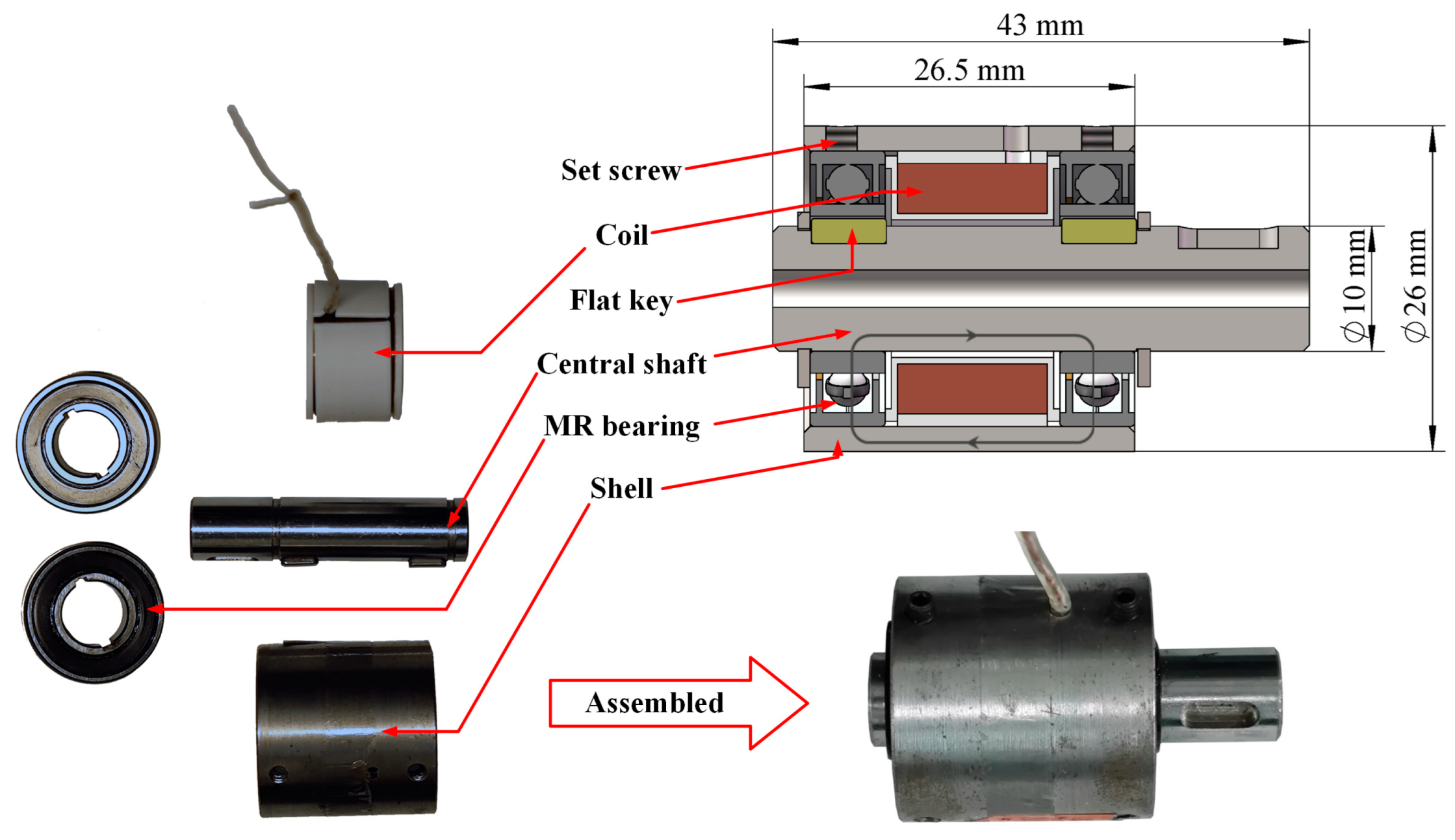
2. Structural Design and Prototype of the MR Damper

MR bearings with controllable damping torque are utilized in an MR damper to raise the torque–volume ratio. They are composed of deep-groove ball bearings and MRGs distributed in the void space inside the bearings. The MRG is fabricated by mixing high-viscosity lubricating grease and iron powder with a particle size of approximately 0.5 μm and stirring for 10 min. To manufacture the MR bearing, the MRG is injected into the deep groove ball bearing when the bearing seals are open. Thereafter, the bearing is placed into the vacuum oven for 5 min to eliminate air bubbles and saturate the space inside the bearing with the MRG. Finally, the bearing seals are closed after several repeated operations. The original bearing seals and the high viscosity of the grease result in a low possibility of oil leakage, which means that no extra seal structures are needed. They also contribute to reducing the sizes of the MR damper. The structure of the MR bearing fits the demands for a high torque–volume ratio. Considering the narrow gaps between the bearing balls and the raceway, the MR material should form chains and generate a high damping coefficient in the presence of a magnetic field. Once the chains come into formation in the narrow gaps, the rolling of the balls will be restrained. At this moment, a large force is required to break the chains and enable the balls to rotate again.
The structure of the MR damper is shown in Figure 1. The damper is mainly composed of a shaft, two MR bearings, a coil, a cylinder shell, and two circlips. Surrounding the central shaft, two MR bearings are fixed on the shaft. The keyways on the inner ring of the bearing enable the shaft to rotate together with the inner ring of the bearing. The coil protected by a 3D-printed shelf lies between the two bearings. A cylinder shell is fixed surrounding the outer ring of the bearings. Two lateral circlips are laid to fasten the bearings. Two copper wires outside the cylinder shell are protected by a heat-shrinkable tube. The keyway located on the right of the central shaft is prepared for the external connection and torque transmission. The central shaft is made of mild steel #25 because of its high saturation magnetization and low coercivity. The total size of the MR damper is 26 mm in diameter and 43 mm in length. The length of the main body minus the connection part is only 26.5 mm. The volume of the damper is 15,366 mm3 in total, which is calculated according to summing the volumes of the shaft and the outer cylinder.
The working principle of the MR damper relies on two different states of the MRG. Without the current in the coil, MRG works as a normal grease with low viscosity and low yield stress, which enables the bearing to rotate smoothly. However, when energizing the coil with current, the MRG works as a sticky elastic solid with a high viscosity due to the chains formed by the iron powders under the magnetic field, as shown in Figure 2. Considering the narrow gap between the balls and the outer ring of the bearing, the chains can easily keep the balls stuck and difficult to rotate. The damping force inside the bearing is sufficiently large to keep the two rings rotating together. For this reason, the designed MR damper can provide a high damping torque. The damping of the MR bearing can also be controlled by the current of the coil, which causes a large damping torque range of the MR damper.

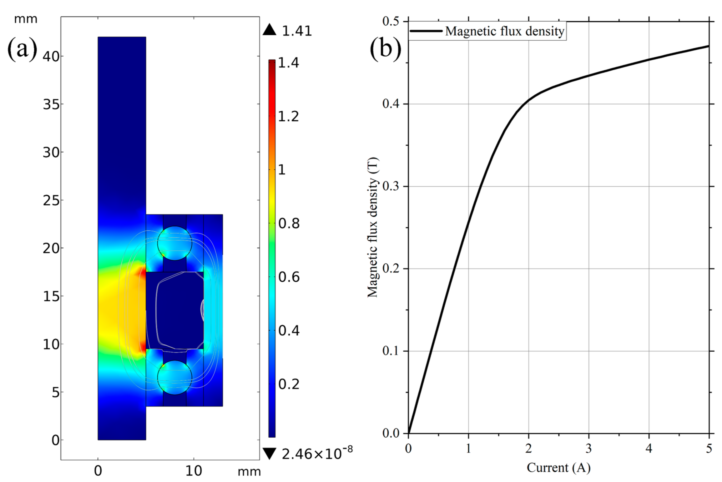
3. Theoretical Analysis of the Torque of the MR Damper

A theoretical model was built to estimate the damping torque of the MR damper. Many models describe the MR effect of MR materials [29] or the response of MR dampers [30,31,32], among which the viscosity of the MR material under different external magnetic fields has huge effects on the performance of the MR material or the dampers. The viscosity of the MR material in dampers also generally relies on the magnetic field produced by the currents in coils. Therefore, obtaining the relationship between the viscosity and the current input is crucial. On the one hand, the relationship between the viscosity of the MRG and the magnetic field was ascertained via material testing using a rheometer (Physica MCR 301, Anton Paar Co., Graz, Austria). In this study, three kinds of MRGs with different mass fractions of iron powders were made. Specifically, the mass fractions of iron powders in the MRGs were 20%, 30%, and 40%. The particle size of iron powder was 0.5 μm on average. The MRG was composed of iron powders and lithium grease, which is widely used in bearing lubrication. On the other hand, the relationship between the magnetic field and the current in the coil was built using magnetic field simulation after material testing.
The viscosity of MRG is strongly influenced by the shear rate. In the material testing of the viscosity of the MRG, the shear rate should be determined according to the actual rotating speed of the bearings. This study assumes that the outer ring of the bearing is static, the inner ring rotates at speed u, and the flow velocity changes linearly along the radial direction. The shear rate γ’ can be calculated by γ’ = ∆u/∆r, where ∆u = u − 0 = u. The size of the bearing used in the experiments was 10 mm in inner diameter and 22 mm in outer diameter, which indicates that ∆r = 6 mm. The minimum controllable speed in the experimental device was ω = 0.016 rad/s, which was also the rotating speed of bearings. The rotating speed u can be given by u = ω · rm = 7.85 × 10⁻⁵ m/s, where rm is the inner diameter of the bearing. By substituting these data into the equation γ’ = ∆u/∆r, the shear rate for torque testing is determined to be γ’ ≈ 0.01 s−1.
Tests on the viscosity of MRG at the abovementioned shear rate under different magnetic flux densities were conducted, as shown in Figure 3. The MRG viscosity grew as the magnetic flux density increased, which shows a satisfactory MR effect. In addition, the MR effect indicated a yield trend when the magnetic flux density was large. The viscosity grew more slowly or even remained stable with the increase in magnetic flux density. This phenomenon is particularly obvious for the MRG with a smaller mass fraction of iron powder. Among MRGs with different mass fractions of iron powders, a larger mass fraction led to a higher maximal viscosity. The zero-field viscosities of these MRGs were near 0.2 × 10⁵ Pa·s, of which the initial zero-field viscosity was slightly higher with the increase in mass fraction. The total curve was approximately in an S-shape, which can be described by a form of the Boltzmann function [33] in (1). In this equation, α is the mass fraction of iron powders in the MRG, and B is the magnetic flux density. A1(α), A2(α), x0(α), and dx(α) shown in Table 1 are four parameters obtained from the fitting of the curves in Figure 3 and the Boltzmann function shown in (1).
v ( B , α ) = A 2 ( α ) + A 1 ( α ) A 2 ( α ) 1 + e B x 0 ( α ) d x ( α )
The variable range of the magnetic field provided by the electromagnet coils is also essential for the MR damper. Measuring the magnetic flux density through a Gaussmeter would be more accurate. However, setting a Gaussmeter for measuring was difficult because of the lack of space for sensors. Therefore, the relationship between the magnetic flux density and the current input was built via magnetic simulation. The magnetic field analysis was conducted in COMSOL software.
The analysis results are shown in Figure 4. In the simulation, a domain probe was placed in the gap between the rolling balls and the MR bearing rings to measure the magnetic flux density. As shown in Figure 4, the maximal magnetic flux density was approximately 1.4 T at the place of the shaft in the middle of the coil, while the minimum was near 0 T. The magnetic flux density in the gap versus the current is shown in Figure 4b. As shown in Figure 4b, the magnetic flux density in the detection area was approximately 0.3 T when the current was 1.2 A. By fitting the curve with the Boltzmann function (the adjusted R2 = 0.9996), the magnetic flux density B is related to the current I by (2). Therefore, the viscosity of the MRG and the current in the coil are related by combining (1) and (2).
B = 0.4575 0.2683 + 0.4575 1 + e I 0.3559 0.6690
Many theories describe the torque of bearings, among which (3) from the article [34] was found suitable for MR bearings.
T = 2 [ μ B D P ( P ax sin θ ) + K 0 f 0 D P 3 ω 1 / 2 ν 2 / 3 ]
By substituting (1) and (2) into (3), the damping torque of bearings can be expressed by (4):
T = 2 [ μ B D P ( P ax sin θ ) + K 0 f 0 D P 3 ω 1 / 2 ( A 2 ( α ) + A 1 ( α ) A 2 ( α ) 1 + e B ( I ) x 0 ( α ) d x ( α ) ) 2 / 3 ]
where Dp is the pitch diameter of the ball track, Pax is the axial preload, θ is the contact angle, f0 is the lubricant fill ratio, ω is the rotational speed of the bearing, and μB and K0 are empirical constants that can be tested in experiments.

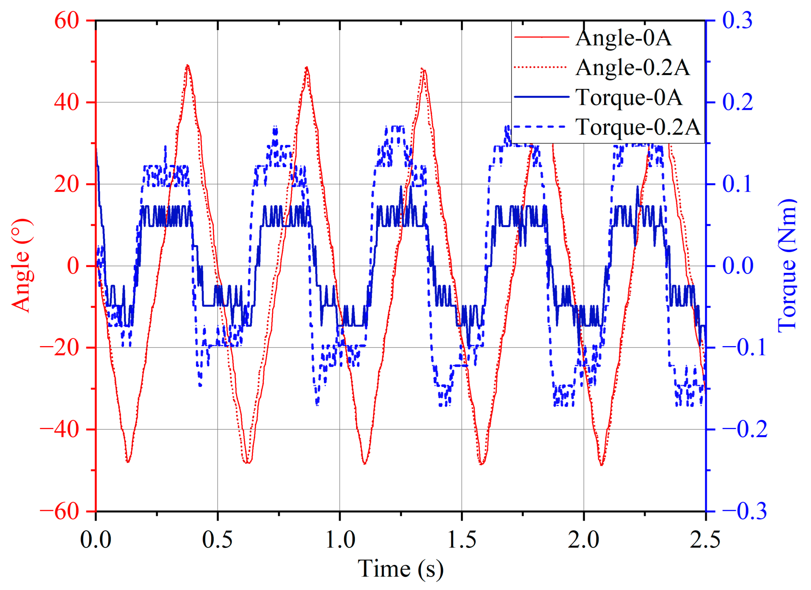
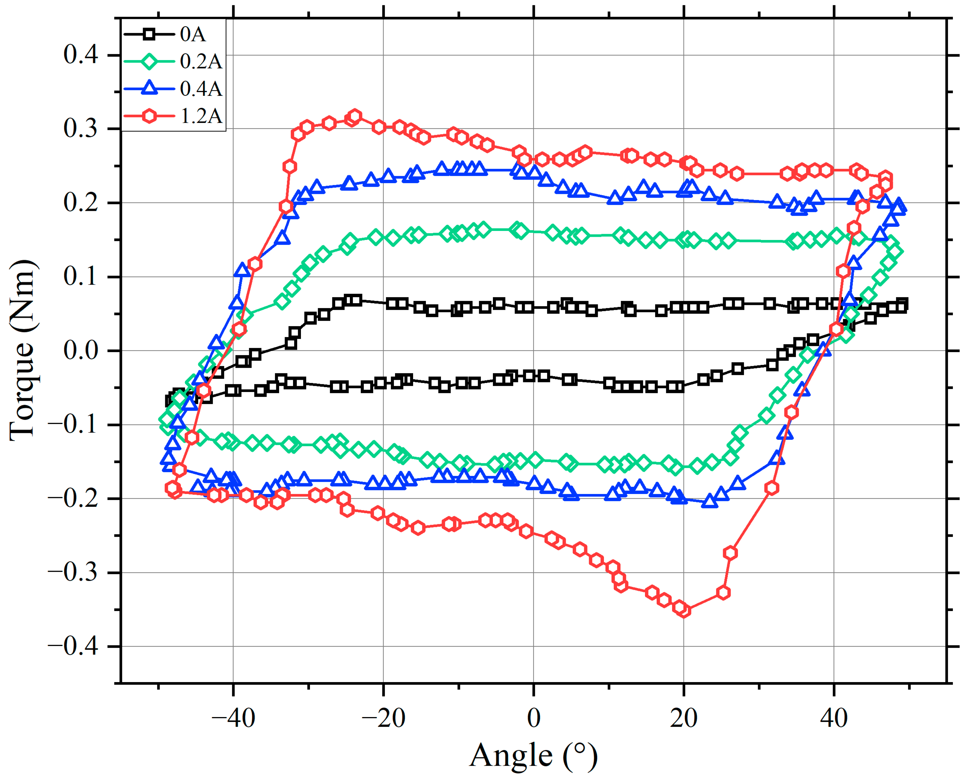
4. Performance Test of the MR Damper

The experimental platform designed to measure the torque of the MR damper is presented in Figure 5. It is mainly composed of three parts. A servo motor with a rated torque reaching 10 Nm lies on the left side. The device in the middle is a torque sensor with a measuring range of 30 Nm and an accuracy of 0.1%. It outputs an analog voltage signal, which is convenient for data acquisition and analysis. The MR damper is placed on the right side. These devices are fixed onto the optical platform through aluminum alloy brackets. They are connected by diaphragm couplings to keep the flexible link. Acquisition of torque data and generation of control signals for the motor and the current in the coil are achieved by a controller (myRIO-1900, NI Co., Austin, TX, USA). During the experiment, myRIO controlled the rotation speed of the motor, and the motor drove the rotation axis connected with the MR damper. The torque sensor measured the rotational torque transmitted on the axis and delivered it to the myRIO. The damping force was adjusted through the current in the coil, which was controlled by the output signal of the myRIO.
During the control of the current in the coil, the coercive force of steel in the bearing is nonnegligible and harmful to controllability. A quite high residual flux density is retained in the steel when the excitation current is off. This condition greatly influences the dynamic response of the MR damper. A control strategy was adopted to reduce the residual flux density, where a sinusoidal current with decreasing amplitude was imposed on the coil at the start of every test. The residual flux density decreased substantially as the direction of the current reversed repeatedly and the amplitude decreased. Therefore, this strategy is essential to reduce the influence of the residual flux density.
Quasistatic tests and dynamic tests were performed to evaluate the performance of the MR damper. In the quasistatic tests, the motor rotated at a speed of 0.15 rpm to simulate the quasistatic condition. This is crucial in the damping maintenance process, which often occurs in many posture-keeping devices or heavyweight-holding devices. In the dynamic tests, the motor turned at a higher speed of 10 rpm with periodically changing directions, as rapid forward and reverse rotation is important in robot and exoskeleton applications. Therefore, these tests were necessary to evaluate the performance of the MR damper.
Quasistatic tests were conducted to evaluate the maximum torque of the damper under different currents. Three kinds of MRGs with different mass fractions of iron powders were utilized in the experiment. The motor on the experimental platform rotated at 0.15 rpm in a fixed direction. The current in the coil varied from 0 A to 1.2 A. Figure 6 indicates that MRG with a larger mass fraction of iron powders resulted in a larger peak torque at the starting rotation process. Specifically, the maximum torques of the MR dampers with 20, 30, and 40 wt% MRGs were 1.4, 1.9, and 3 Nm, respectively.
Theoretical torque is calculated with (4) in Section 3. The empirical constants μB and K0 are shown as follows: μB = −0.01785, K0 = 5.048 × 10⁻⁹. These constants were substituted in (4) to calculate the theoretical torque, which was compared with the experimental torque in Figure 6. The fitting parameters for the coefficient of determination are R2 = 0.9571 and adjusted R2 = 0.9470, which indicates that the fitting process is successful with (4).
The volume of the MR damper was 15,366 mm3. The maximum torque in the quasistatic test was 2.92 Nm. Based on these data, the torque–volume ratio was obtained as 190 kN/m2. It was achieved when the current in the coil was approximately 1.2 A and the power was approximately 10.9 W. Table 2 shows the comparisons between the MR damper proposed in the study and other rotary dampers. In general, the proposed damper has an extremely high torque–volume ratio. Specifically, the torque–volume ratio of the proposed MR damper is approximately four times higher than that presented by Carlos Rossa et al. [22], which is the highest ratio reported before.
In the dynamic test, the MR damper utilized MRG with 40 wt% iron powder. This test was intended to illustrate the relationship between the torque and the rotation angle. An angle encoder was fixed near the shaft to measure the rotation angle of the damper, and the output data of this encoder were also transmitted to the myRIO and saved in the computer. A smoothing operation was applied to the collected data to filter the noise signal. The results are shown in Figure 7.
Figure 7 indicates the relationship between the rotational angle and the torque. The amplitude of the angle was nearly 50°. The speed was nearly constant in the experiments, while the direction changed periodically. In each period, the torque changed abruptly when the rotating direction reversed. The torque remained much steadier during the rest of the period. The MR damper was tested at different currents in the coil. Figure 8 shows the variation in torque–angle loops under different currents. In general, the maximum torque and the energy dissipated per cycle increased simultaneously as the current rose. When the current reached 1.2 A, the amplitude of the torque reached 0.3 Nm, which is approximately three times the torque without currents.
However, a defect in the designed MR damper appeared in the dynamic experiment. Compared with Figure 6, the maximum damping torque decreased to 0.3 Nm, which is only one-tenth of the torque in the quasistatic condition. This problem is probably due to the fact that the MRG is distributed around the outer ring of the bearing due to centrifugal force when the bearings rotate at high speed. This condition leads to the lack of MRG at the gap between the inner ring and the rotational balls. Therefore, the proposed damper is more effective in low-speed situations.

5. Conclusions

In this study, a rotary MR damper based on MR bearings was proposed, fabricated, and tested. The proposed damper equipped with MR bearings achieved an extremely high torque density. The torque–volume ratio of the damper reached 196 kN·m−2. Compared with other rotary dampers in the existing studies, the proposed MR damper has a quite high torque–volume ratio that is nearly four times higher than that of other dampers. A theoretical model was also built in this study to calculate the theoretical torque of the MR damper. The theoretical maximum torque was 2.7 Nm, which is comparable to the experimental maximum torque of 2.92 Nm. This MR damper has great potential in applications in robotic joints and aerospace, where a small volume and a high torque are needed.

Author Contributions

Conceptualization, S.S.; methodology, S.Z. (Shengfeng Zhu); resources, S.Z. (Shiwu Zhang), X.G., W.L.; writing—original draft preparation, S.Z. (Shengfeng Zhu); writing—review and editing, N.G., J.Y. and S.S.; funding acquisition, S.S. All authors have read and agreed to the published version of the manuscript.

Funding

This research was funded by the Anhui’s Key R&D Program of China (Grant Nos. 202104a05020009 and 202104b11020004), the National Natural Science Foundation of China (Grant Nos. 52005474 and 52105081), USTC start-up funding (KY2090000067), and the Fundamental Research Funds for the Central Universities (WK2480000009).

Data Availability Statement

Not applicable.

Acknowledgments

Thanks to the CAS Key Laboratory of Mechanical Behavior and Design of Materials, Department of Precision Machinery and Precision Instrumentation, University of Science and Technology of China for supporting this work.

Conflicts of Interest

The authors declare no conflict of interest.

References

  1. Park, B.J.; Fang, F.F.; Choi, H.J. Magnetorheology: Materials and application. Soft Matter 2010, 6, 5246–5253. [Google Scholar] [CrossRef]
  2. Brancati, R.; Di Massa, G.; Pagano, S. Investigation on the Mechanical Properties of MRE Compounds. Machines 2019, 7, 36. [Google Scholar] [CrossRef] [Green Version]
  3. De Vicente, J.; Klingenberg, D.J.; Hidalgo-Alvarez, R. Magnetorheological fluids: A review. Soft Matter 2011, 7, 3701–3710. [Google Scholar] [CrossRef]
  4. Li, Y.; Li, J.; Li, W.; Du, H. A state-of-the-art review on magnetorheological elastomer devices. Smart Mater. Struct. 2014, 23, 123001. [Google Scholar] [CrossRef]
  5. Yu, M.; Ju, B.; Fu, J.; Liu, X.; Yang, Q. Influence of composition of carbonyl iron particles on dynamic mechanical properties of magnetorheological elastomers. J. Magn. Magn. Mater. 2012, 324, 2147–2152. [Google Scholar] [CrossRef]
  6. Hu, T.; Xuan, S.; Ding, L.; Gong, X. Stretchable and magneto-sensitive strain sensor based on silver nanowire-polyurethane sponge enhanced magnetorheological elastomer. Mater. Des. 2018, 156, 528–537. [Google Scholar] [CrossRef]
  7. Mohamad, N.; Mazlan, S.A.; Choi, S.B.; Nordin, M.F.M. The Field-Dependent Rheological Properties of Magnetorheological Grease Based on Carbonyl-Iron-Particles. Smart Mater. Struct. 2016, 25, 095043. [Google Scholar] [CrossRef]
  8. Guo, S.; Yang, S.; Pan, C. Dynamic Modeling of Magnetorheological Damper Behaviors. J. Intell. Mater. Syst. Struct. 2006, 17, 3–14. [Google Scholar] [CrossRef]
  9. Bai, X.-X.; Hu, W.; Wereley, N.M. Magnetorheological Damper Utilizing an Inner Bypass for Ground Vehicle Suspensions. IEEE Trans. Magn. 2013, 49, 3422–3425. [Google Scholar] [CrossRef]
  10. Nguyen, Q.-H.; Choi, S.-B. Optimal design of a vehicle magnetorheological damper considering the damping force and dynamic range. Smart Mater. Struct. 2008, 18, 015013. [Google Scholar] [CrossRef]
  11. Wang, C.; Zhang, J.; Liu, G.; Shang, H.; Wei, X. Design and Performance Analysis of a Double-Outlet-Rod Magnetorheological Damper for Impact Load. Machines 2022, 10, 1099. [Google Scholar] [CrossRef]
  12. Imaduddin, F.; Mazlan, S.A.; Zamzuri, H. A design and modelling review of rotary magnetorheological damper. Mater. Des. 2013, 51, 575–591. [Google Scholar] [CrossRef]
  13. Piantini, S.; Giorgetti, A.; Baldanzini, N.; Monti, C.; Pierini, M. Design of a Motorcycle Steering Damper for a Safer Ride. Machines 2020, 8, 24. [Google Scholar] [CrossRef]
  14. Lee, J.-H.; Han, C.; Ahn, D.; Lee, J.K.; Park, S.-H.; Park, S. Design and Performance Evaluation of a Rotary Magnetorheological Damper for Unmanned Vehicle Suspension Systems. Sci. World J. 2013, 2013, 1–10. [Google Scholar] [CrossRef] [Green Version]
  15. Saini, R.S.T.; Chandramohan, S.; Sujatha, S.; Kumar, H. Design of bypass rotary vane magnetorheological damper for prosthetic knee application. J. Intell. Mater. Syst. Struct. 2021, 32, 931–942. [Google Scholar] [CrossRef]
  16. Yang, T.; Gao, Y.; Zhao, J.; Wang, S.; Zhu, Y. A rotary magnetorheological fluid damper for pathological tremor suppression. In Proceedings of the 2012 IEEE International Conference on Mechatronics and Automation, Chengdu, China, 5–8 August 2012; pp. 575–580. [Google Scholar] [CrossRef]
  17. Yu, J.; Dong, X.; Zhang, Z.; Chen, P. A novel scissor-type magnetorheological seat suspension system with self-sustainability. J. Intell. Mater. Syst. Struct. 2018, 30, 665–676. [Google Scholar] [CrossRef]
  18. Li, W.H.; Du, H. Design and Experimental Evaluation of a Magnetorheological Brake. Int. J. Adv. Manuf. Technol. 2003, 21, 508–515. [Google Scholar] [CrossRef]
  19. Park, E.J.; Stoikov, D.; Falcao Da Luz, L.; Suleman, A. A performance evaluation of an automotive magnetorheological brake design with a sliding mode controller. Mechatronics 2006, 16, 405–416. [Google Scholar] [CrossRef]
  20. Huang, J.; Zhang, J.; Yang, Y.; Wei, Y. Analysis and design of a cylindrical magneto-rheological fluid brake. J. Mater. Process. Technol. 2002, 129, 559–562. [Google Scholar] [CrossRef]
  21. Yu, J.; Dong, X.; Wang, W. Prototype and test of a novel rotary magnetorheological damper based on helical flow. Smart Mater. Struct. 2016, 25, 025006. [Google Scholar] [CrossRef]
  22. Rossa, C.; Jaegy, A.; Micaelli, A.; Lozada, J. Development of a multilayered wide-ranged torque magnetorheological brake. Smart Mater. Struct. 2014, 23, 025028. [Google Scholar] [CrossRef]
  23. Yu, J.; Dong, X.; Su, X.; Qi, S. Development and characterization of a novel rotary magnetorheological fluid damper with variable damping and stiffness. Mech. Syst. Signal Process. 2021, 165, 108320. [Google Scholar] [CrossRef]
  24. Garcia, E.; Arevalo, J.C.; Muñoz, G.; Gonzalez-De-Santos, P. On the Biomimetic Design of Agile-Robot Legs. Sensors 2011, 11, 11305–11334. [Google Scholar] [CrossRef] [PubMed] [Green Version]
  25. Wang, D.; Wang, Y.; Zi, B.; Cao, Z.; Ding, H. Development of an active and passive finger rehabilitation robot using pneumatic muscle and magnetorheological damper. Mech. Mach. Theory 2020, 147, 103762. [Google Scholar] [CrossRef]
  26. Kim, J.-H.; Oh, J.-H. Development of an above knee prosthesis using MR damper and leg simulator. In Proceedings of the 2001 ICRA. IEEE International Conference on Robotics and Automation (Cat. No. 01CH37164), Seoul, Republic of Korea, 21–26 May 2001; pp. 3686–3691. [Google Scholar] [CrossRef]
  27. Zou, J.; Zhu, A.; Song, J.; Dang, D.; Zhou, X.; Zhang, Y. A novel magnetorheological damper combing multi-disc and multi-drum structures. In Proceedings of the 2022 19th International Conference on Ubiquitous Robots (UR), Jeju, Republic of Korea, 4–6 July 2022; pp. 52–57. [Google Scholar] [CrossRef]
  28. Gudmundsson, K.H.; Jónsdóttir, F.; Thorsteinsson, F. A geometrical optimization of a magneto-rheological rotary brake in a prosthetic knee. Smart Mater. Struct. 2010, 19, 035023. [Google Scholar] [CrossRef]
  29. Wang, X.; Gordaninejad, F. Flow analysis of field-controllable, electro-and magneto-rheological fluids using Herschel-Bulkley model. J. Intell. Mater. Syst. Struct. 1999, 10, 601–608. [Google Scholar] [CrossRef]
  30. Choi, S.; Lee, S.-K.; Parkb, Y.P. A hysteresis model for the field-dependent damping force of a magnetorheological damper. J. Sound Vib. 2001, 245, 375–383. [Google Scholar] [CrossRef]
  31. Wereley, N.M.; Pang, L.; Kamath, G.M. Idealized hysteresis modeling of electrorheological and magnetorheological dampers. J. Intell. Mater. Syst. Struct. 1998, 9, 642–649. [Google Scholar] [CrossRef]
  32. Yu, M.; Liao, C.R.; Chen, W.M.; Huang, S.L. Study on MR Semi-active Suspension System and its Road Testing. J. Intell. Mater. Syst. Struct. 2006, 17, 801–806. [Google Scholar] [CrossRef]
  33. Gao, Y.; Zhang, Z.; Yao, W.; Ying, Q.; Long, C.; Fu, X. Forecasting the cumulative number of COVID-19 deaths in China: A Boltzmann function-based modeling study. Infect. Control. Hosp. Epidemiol. 2020, 41, 841–843. [Google Scholar] [CrossRef] [Green Version]
  34. Glassow, F. Despin bearing technology and applications for communications satellites. In Proceedings of the 3rd Communications Satellite Systems Conference, Los Angeles, CA, USA, 6–8 April 1970; p. 459. [Google Scholar] [CrossRef]
  35. Carlson, J.D.; Leroy, D.F.; Holzheimer, J.C.; Prindle, D.R.; Marjoram, R.H. Controllable Brake. U.S. Patents US5842547A, 1 December 1998. [Google Scholar]
  36. Senkal, D.; Gurocak, H. Serpentine flux path for high torque MRF brakes in haptics applications. Mechatronics 2010, 20, 377–383. [Google Scholar] [CrossRef]
  37. Liu, B.; Li, W.H.; Kosasih, P.B.; Zhang, X.Z. Development of an MR-brake-based haptic device. Smart Mater. Struct. 2006, 15, 1960–1966. [Google Scholar] [CrossRef]
  38. Guo, H.; Liao, W.-H. Optimization of a multifunctional actuator utilizing magnetorheological fluids. In Proceedings of the 2011 IEEE/ASME International Conference on Advanced Intelligent Mechatronics (AIM), Budapest, Hungary, 3–7 July 2011; pp. 67–72. [Google Scholar]
  39. Nam, Y.-J.; Moon, Y.-J.; Park, M.-K. Performance Improvement of a Rotary MR Fluid Actuator Based on Electromagnetic Design. J. Intell. Mater. Syst. Struct. 2007, 19, 695–705. [Google Scholar] [CrossRef]
Figure 1. Structural design and prototype of the designed damper. The sectional view of the 3D model is on the top right. The flux direction is marked with a gray line. The structural components of the MR damper are on the left. The MR damper prototype, which is assembled from the components, is on the bottom right.
Machines 11 00368 g001
Figure 2. Chain aggregation behavior of the MRG in MR bearings: the blue circle at the top refers to a bearing ball, while the bottom blue part refers to the outer ring of the bearing. Small black circles represent iron powders, and yellow lines with arrows refer to magnetic induction lines.
Machines 11 00368 g002
Figure 3. Experimental measurements of the viscosity of the MRGs from top to bottom are 40%, 30%, and 20%. The magnetic field varies from 0 T to 0.8 T, and the shear rate is 0.01 s−1.
Machines 11 00368 g003
Figure 4. Magnetic field simulation of the MR damper. (a) Magnetic flux density distribution of the MR damper when the current in the coil is 1 A. (b) Magnetic flux density at the area of the MRG around the rolling balls.
Machines 11 00368 g004
Figure 5. Experimental setup for the torque test including motor, torque sensor, MR damper, and other connection and location fixing parts.
Machines 11 00368 g005
Figure 6. Torque–current curves of MRGs with different mass fractions: the three curves from top to bottom represent MRGs with iron powder percentages of 40%, 30%, and 20%. The current varies from 0 A to nearly 1.2 A.
Machines 11 00368 g006
Figure 7. Dynamic time-domain signal of torque and rotational angle. The sampling frequencies of the current and torque signals are both 200 Hz.
Machines 11 00368 g007
Figure 8. Torque–angle curve with different currents: the currents are 0 A, 0.2 A, 0.4 A, and 1.2 A.
Machines 11 00368 g008
Table 1. Fitting parameters of the viscosity curves.
αA1(α)A2(α)x0(α)dx(α)
20%815393,5550.175590.08557
30%−19,2972.0005 × 1050.175650.10752
40%−60,7494.1824 × 1050.198120.13147
Table 2. Comparison among different rotary dampers.
ParametersUnitDesigned Damper in This StudyCarlos Rossa et al. [22]Lord Corp. RD-2078-1 [35]Senkal and Gurocak [36]Liu et al. [37]Guo and Liao [38]Nam et al. [39]
Max torqueNm2.925.3410.970.484.2
Lengthmm433935.789.7211838
Radiusmm133096.631.75782560
PowerW10.919152052
Torque/vol.kN·m−219048.112.538.317.413.69.8
Disclaimer/Publisher’s Note: The statements, opinions and data contained in all publications are solely those of the individual author(s) and contributor(s) and not of MDPI and/or the editor(s). MDPI and/or the editor(s) disclaim responsibility for any injury to people or property resulting from any ideas, methods, instructions or products referred to in the content.

