Article

Study on the Service Performance of a Two-Stage Floating-Ring Isolation Seal for a High-Speed Turbopump with a Cryogenic Medium

Research Center of Fluid Sealing Technology, Beijing University of Chemical Technology, Beijing 100029, China
*
Author to whom correspondence should be addressed.
Machines 2023, 11(3), 373; https://doi.org/10.3390/machines11030373
Submission received: 8 December 2022 / Revised: 3 March 2023 / Accepted: 7 March 2023 / Published: 10 March 2023
(This article belongs to the Special Issue Selected Papers from CITC2022)

Abstract

:
The reliability and stability of the seal at the fuel-supply end of a rocket-engine turbopump are important factors in determining safety. Conventional single-stage floating rings used for the isolation-sealing of cryogenic media are highly susceptible to operational instability during startup and shutdown, which places demands on the seals’ structure, size, and material properties. In this study, a two-stage floating-ring isolation seal with a non-slotted main sealing surface was designed using a tangential air-intake mode. Based on the full-size three-dimensional finite-volume model, the leakage characteristics of the floating ring during operation were calculated, taking into account the effect of the “inlet effect” on the seal’s performance. Combining the temperature and pressure distributions of the sealing system under cryogenic operating conditions, calculated using a numerical simulation, a reliability analysis of various inlet directions and two kinds of floating-ring schemes was carried out on a self-constructed service-performance test bench. The results indicate that the main wear location of the non-slotted floating ring occurs on the auxiliary sealing surface, with stable working performance. When the inlet direction and spindle-rotation direction are the same, this is more conducive to ensuring the stability of seal performance in practical applications. The results of the current research are instructive for designing floating-ring isolation seals for turbine pumps.

1. Introduction

As a key performance component of a rocket-engine turbopump, the isolation seal between the fuel pump and the oxygen pump in the turbopump can prevent liquid oxygen, leaking between the shafts, from meeting with liquid methane and causing an explosion. A schematic diagram of a liquid rocket-fuel pump is shown in Figure 1. The isolation-seal system works on the shaft between the oxygen pump and the fuel pump. At present, rocket engines are gradually developing towards high-parameter requirements, with the requirements being: low temperature, high speed, high-pressure difference, and high vibration. This demands higher requirements for the sealing-performance and reliability of sealing systems [1]. An isolation seal will ensure the quantitative and stable circulation of the isolation gas, and the reliable stability of the seal under the rated working conditions.
A floating-ring seal has the characteristics of: simple structure, low cost, and long service life. As a non-contact seal, its sealing performance mainly depends on the gas-film state of the main sealing surface. In order to study its sealing performance, numerical-calculation methods have been used to construct the dynamic performance of the floating ring seal [2,3]; an eccentric fluid membrane was also constructed using CFD to calculate the floating ring’s uplift performance, opening law, and leakage characteristics [4,5,6]. Arghir et al. [7] developed an analytical model for the mechanical calculation of floating rings, to calculate the dynamic characteristics of floating rings from the perspective of force analysis. Ma et al. [8] studied the relationship between the leakage of the floating-ring seal and the spring’s specific pressure and other related structural parameters; these authors also studied optimization of the floating-ring-seal structure’s parameters. The reliability and stability of the floating-ring seal under abnormal operating conditions is an issue that requires special attention. Bae et al. [9] verified the seal’s reliability by analyzing the frictional-uplift force applied to floating-ring seals in turbine pumps, while the experimental results fit well with the simulation results. Antoine et al. [10] proposed a theoretical model for predicting the dynamic response of floating rings, developed from analyzing the compensating properties of the floating ring gap for vibration at different frequency-speed conditions. Shi et al. [11,12] established a mathematical model of the seal-clearance of floating rings, and studied the friction between the runway and the floating ring under rough working conditions. Li et al. [13] found that floating-ring seals outperformed labyrinth seals, by studying the leakage characteristics of floating-ring seals and labyrinth seals under cold/hot conditions. Oike et al. [14] investigated the feasibility of applying floating ring seals to gas–liquid two-phase conditions and obtained the key parameters affecting the seal’s performance. Regarding the pump-shaft’s vibration characteristics, the pump’s rotor dynamics characteristics have also been studied [15,16]. Choi et al. [17] and Balakh et al. [18,19] used a floating-ring seal rotor system as their study object to analyze the influence of the floating ring on the stability of the whole system. Wang et al. [20] conducted experimental research and analysis on the friction performance of a split floating-ring stray in the bearing cavity.
The problem of the unstable operation of a single-stage floating ring during the start-up phase still needs to be solved. Due to the gas flow entering the sealing-throttle channel through the cavity, most of the studies on floating-ring seals have used analytical calculations for a single floating-ring eccentric film, ignoring the influence of the air-inlet direction and the inlet effect on the sealing performance. To ensure the stability of the sealing system, a two-stage floating ring structure is adopted. Meanwhile, a full-size three-dimensional flow field model is established to analyze the influence of the “inlet effect” on the seal performance of the floating ring and the influence of the inlet direction on the stability of the seal system.

2. Sealing Structure and Principle

2.1. Sealing Structure

The working conditions are an important factor in the design of a seal structure. The seal proposed in this paper is developed for low-temperature working conditions and isolation requirements. The corresponding working conditions are listed in Table 1.
The floating-ring isolation seal is mainly composed of graphite rings, a waveform spring, a runway, an auxiliary seal, and a sealing chamber, and its two-dimensional structure is shown in Figure 2. In particular, a tangential air-inlet mode is adopted. The floating-ring seal as a throttling seal, the floating ring, the runway gap, and the throttling length are important parameters affecting the leakage characteristics. The maximum gap is 0.0405 mm on one side of the design, the flow length of the primary floating link is 9.5 mm, and the flow length of the second floating link is 7.5 mm.
To meet the requirements of low temperature and high reliability, the materials of sealing components need to be selected reasonably, and the main materials of sealing components are shown in Table 2.
The direction of the arrow in Figure 2 is the direction of the isolated gas flow, i.e. the main leakage path, and the interpretation of the nozzle is shown in Table 3.
The main sealing surface of the floating ring has a non-slotted structure. The appearance of the graphite ring and the main sealing surface are shown in Figure 3.

2.2. Sealing Principle

In the initial stationary state, the floating ring is subject to gravity G, its upper inner diameter is in contact with the outer diameter of the runway, and the auxiliary sealing surface is in a non-contact state with the cavity. The auxiliary sealing surface FA provides a support force of 0.
The inlet direction is tangential to the runway direction; when the seal is in operation, the forces are as shown in Figure 4. When the isolation gas-inlet pressure increases, the auxiliary sealing surface of the floating ring is close to the cavity, and the isolation gas flows on both sides in sequence through the primary and secondary floating-ring seal main-sealing channel. At this time, the auxiliary sealing surface is tightened and FA gradually increases, while frictional force Ff is generated. As the spindle rotates, the gas generates a buoyancy force, FDP, on the floating ring. When the buoyancy force (FDP) on the gas film is balanced with the frictional resistance (Ff) on the auxiliary sealing surface and the gravity (G) of the floating ring, the floating ring reaches a stable motion. The leakage channel is at the gap between the floating ring and the runway.
In the force analysis of the floating ring, in the fully floating state, the relationship among the forces is as described in Equation (1):
F f + F D P G = 0 ( P o u t × S o u t + F S ) ( P i n × S i n + F A ) = 0
where Ff indicates the friction between the auxiliary sealing surface of the floating ring and the cavity, N; FDP indicates the floating-ring air-film buoyancy force, N; G is the gravity of the floating ring, N; Pout denotes the pressure at the seal inlet, MPa; Sout is the area of the end surface at the floating ring inlet, mm2; Pin denotes the pressure at the sealing outlet, MPa; Sin is the area of the end-surface at the floating ring outlet, excluding the auxiliary sealing surface, mm2; FS indicates the wave-spring force, N; and FA indicates the auxiliary sealing surface support force, N.

2.3. Sealing Performance

2.3.1. Leakage Characteristics

Leakage (q), measured using an electronic gas volumetric-flow meter, is one of the most important indicators of the stability of floating-ring seal operation as well as seal performance. When the floating ring reaches a stable operating condition of complete floatation, the leakage volume shows a trend of no fluctuation and linear change.

2.3.2. Floating Ring Operating Stability

The stability of the floating-ring operation is an important factor in the reliability of the floating-ring seal. In the face of low-temperature and high-vibration conditions, the floating ring is in a dynamic balance between floating and eccentricity during operation, and the floating ring is prone to cavity bumping, which leads to graphite-ring breakage; at the same time, the floating ring does not float, normally resulting in the follow-rotation phenomenon, which can lead to seal failure caused by the floating ring restricting runway rotation or by violent friction of the auxiliary sealing surface.

3. Finite Element Simulation
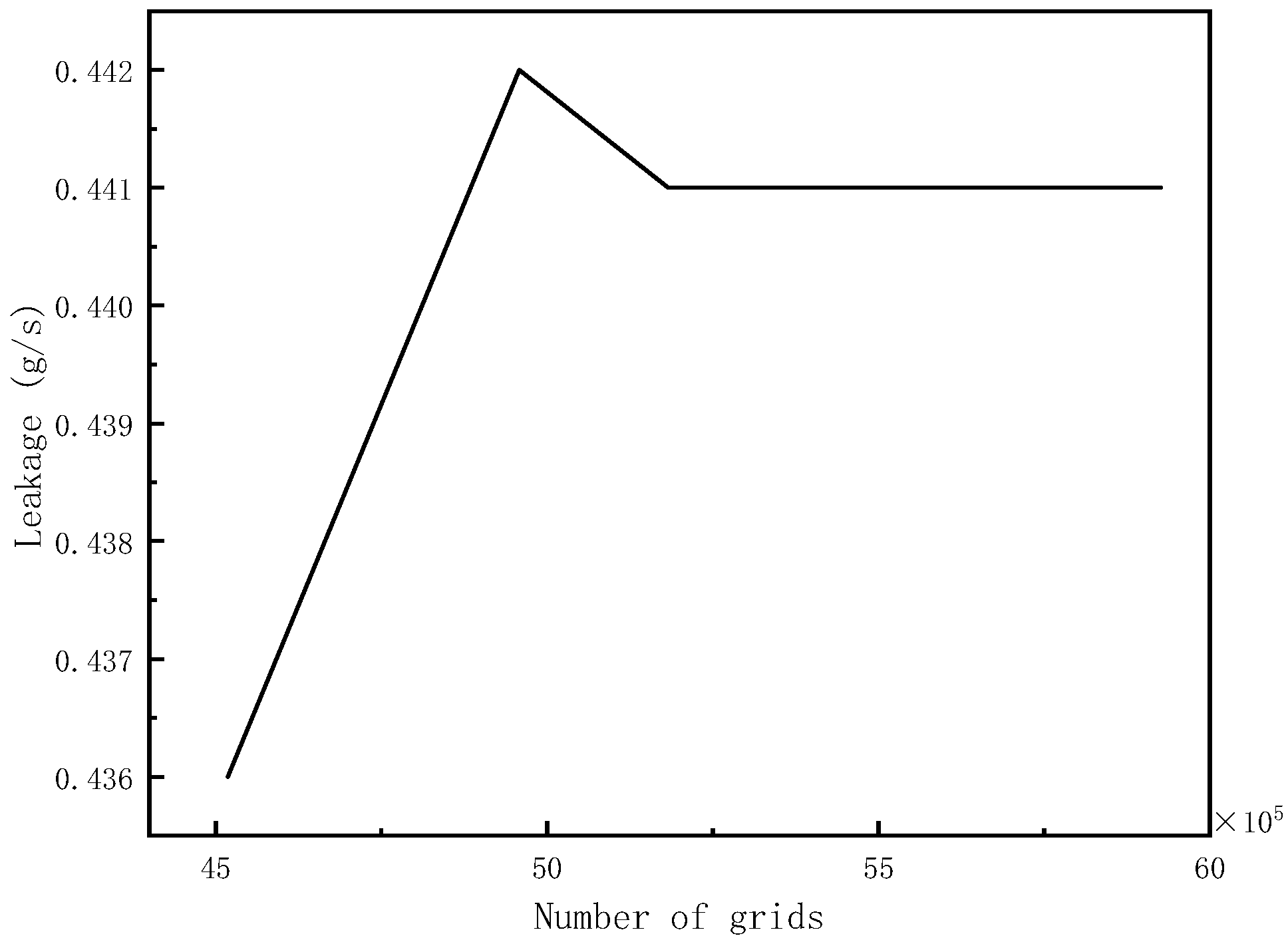
3.1. Model and Mesh

A three-dimensional fluid domain model was constructed using Solidworks. To study the influence of the inlet direction on the sealing performance, four homogeneous tangential inlets were established in the circumferential direction, while the fluid space in the chamber where the floating ring is located was built to consider the inlet effect. The fluid domain model is shown in Figure 5.
Since the thickness of the air film is only 0.04 mm, which is too small compared with the size of the fluid domain, the air-film part needs to be reasonably cut from the whole, and then the data-exchange interface needs to be constructed to facilitate the grid division. The air-film part is divided by a sweeping method to ensure that the number of grid layers in the air-film thickness direction is more than three, and the fluid domain grid is shown in Figure 6. Following grid-independent verification in Figure 7, the final number of grids is determined to be 5,441,666, which meets the calculation-accuracy requirements.

3.2. Numerical Simulation Pre-Processing

According to the main objective of this study, only the case where the floating-ring seal is operating under ideal operating conditions is considered in the numerical simulation. Therefore, we consider that the floating ring operates in the following conditions:
  • The isolated gas is the ideal gas;
  • The floating ring is in a fully-floating state;
  • The floating-ring auxiliary-sealing surface is completely tightened to the chamber.
According to the sealing principle and working conditions, set the boundary conditions as shown in Table 4:
Since the numerical simulation of the flow field takes into account the influence of the fluid flow in the chamber before entering the floating-ring seal gap on the calculation, the turbulence model that was chosen was RNG k-epsilon. This turbulence model is more advantageous for high-speed flow and low Reynolds-number calculations. The standard wall function is used for the wall function. In addition, the energy equation calculation needs to be opened. Considering the grid complexity, the SimpleC calculation method was chosen.

4. Seal Service Performance Test

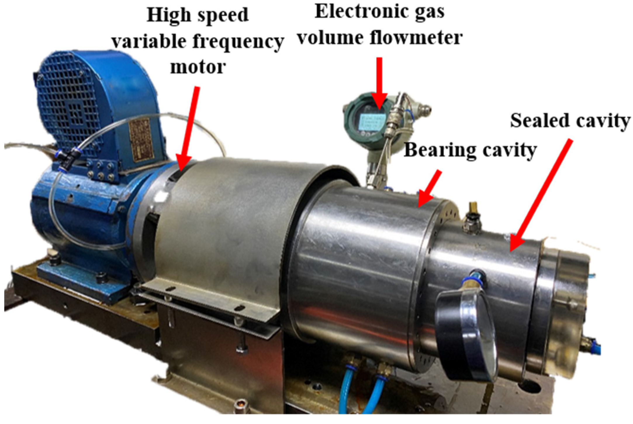
4.1. Test Bench Construction and Preparation

The seal-test stand was built on a high-speed inverter motor and connected to the bearing chamber, seal chamber, and auxiliary systems such as the pressure gauge, electronic volume-flow meter, bearing-temperature measurement, and lubrication system, etc. The test stand is shown in Figure 8. The test stand has the capability of both the principle test and the service-performance test.
The motor-input frequency is adjusted through the digital console to change the rotational speed. The motor-output shaft is connected to the bearing-chamber spindle through a coupling and drives the spindle in the sealing chamber to rotate. A bearing-lubrication system, and temperature monitoring, are used to ensure safe and reliable operation of the bearing chamber.
There is a liquid-nitrogen filling port on the outer cavity of the secondary floating ring, which can provide an ultra-low temperature environment for the test by providing a small amount of liquid nitrogen. After providing a small amount of liquid nitrogen and waiting for the liquid nitrogen to vaporize completely, the filling port is closed and the test is started. The motor rotation and the gas-inlet supply are used to simulate the working conditions of the seal assembly. The test phenomenon is observed under the working conditions and the relevant data are measured.

4.2. Test Procedure

To verify the sealing performance of the floating-ring isolation seal assembly, principle tests and in-service performance tests are required to obtain the variation in the leakage characteristics of the floating ring isolation seal and to verify the stability of the floating ring seal. The test procedure is as follows:
  • Completion of the assembly of the coupling, bearing cavity, and sealing cavity in the order of test-bench assembly;
  • Connection of leak-measurement devices, pressure gauges, bearing temperature measurement, and lubrication systems, and connection of isolated gas lines to the inlet;
  • Change the inlet pressure of the isolated gas sequentially in the motor-stop state, 0–0.5 MPa, and change the inlet pressure sequentially at intervals of 0.05 MPa; wait for the electronic gas-volume flowmeter to indicate a stable number and record the leakage amount;
  • A small amount of liquid nitrogen is added to the outer chamber of the secondary floating ring, and the next step is performed after the liquid nitrogen in the chamber has vaporized and there is no visible liquid nitrogen;
  • Start the fan and motor, increase the motor speed, and measure the side inlet-pressure leakage at five speeds of 6000 rpm, 10,000 rpm, 12,000 rpm, 14,000 rpm, and 20,000 rpm;
  • Change the tangential air-inlet direction, repeat test steps (3) and (4), observe the test phenomenon, and record the leakage-volume data;
  • Operate continuously for 600 h at 20,000 rpm and 0.5 MPa inlet pressure to observe the test phenomenon and floating ring integrity.

5. Results

Combining the finite-element simulation and test results, the variation-law of leakage, including spindle speed and isolation gas inlet pressure, was analyzed, and the stability of the seal was analyzed by observing its surface condition via a service-performance test.

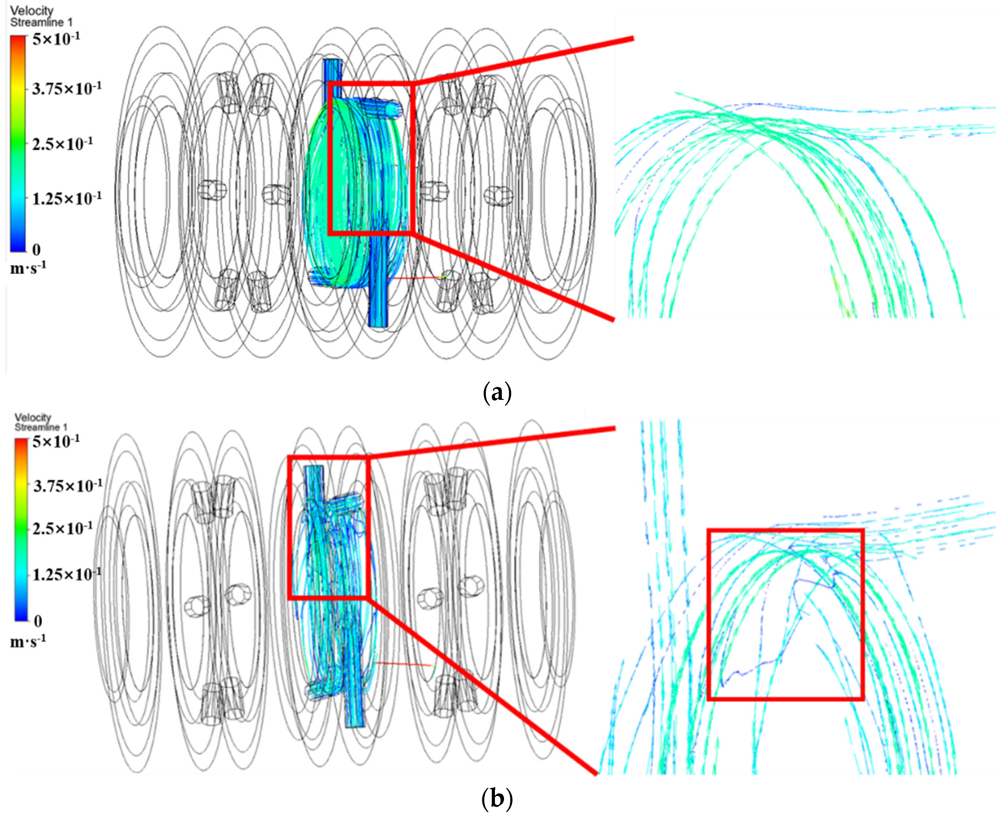
5.1. Flow Field Flow Characteristics

The flow states of the intermediate cavity-flow field in both inlet directions were obtained by finite-element simulation, as shown in Figure 9.
The flow diagrams of the middle chamber in both intake directions show that the flow lines are uniform and stable when the air-inlet direction is the same as the spindle-rotation direction. However, when the air-inlet direction is opposite, the intermediate cavity-flow lines are chaotic and reverse-flow occurs near the intake port. This affects the subsequent intake and makes the middle-chamber airflow unstable.
The temperature-field contour and pressure contour, in the main leakage channel, are shown in Figure 10.
In the two-stage floating-ring sealing cavity, the temperature is roughly 294 K. The low-temperature location is mainly concentrated in the back side of the second-stage floating ring, which mainly affects the second-stage floating ring; it can be seen through the pressure-contour diagram that the inlet effect does not have much influence on the floating-ring sealing performance. The pressure drop mainly occurs at the gap between the inner diameter of the floating ring and the runway, and the pressure in the cavity is stable.

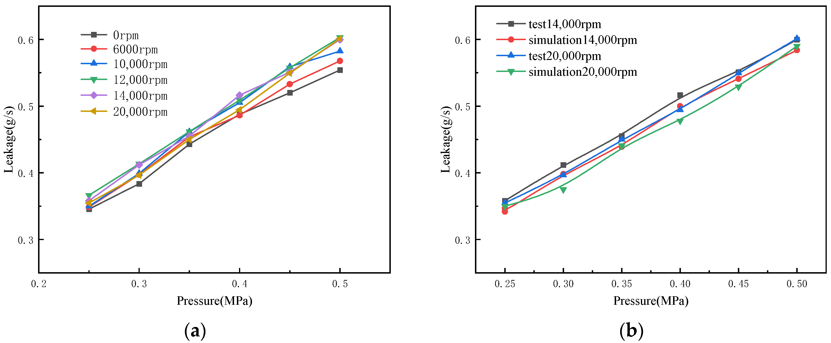
5.2. Leakage Characteristics of the Floating Ring Isolation Seal

5.2.1. The Air Inlet Direction Is in the Same Direction as the Spindle Rotation Direction

Through the principle test and finite-element simulation analysis, the variation-law of the leakage volume, with the increase in inlet pressure at different speeds and the same direction of inlet- and spindle-rotation, is shown in Figure 11.
Comparing the simulation results with the test data, the leakage error is less than 5%, which indicates that the simulation-calculation results are considered reliable.
It can be seen from the test data that the leakage volume mainly varies with the inlet pressure and is not greatly affected by the rotational speed. In particular, when the inlet pressure is 0.25 MPa, the leakage volume is stable, at which time the floating ring seal enters a stable working condition, and the leakage volume ranges from 0.35–0.6 g/s at this time.
Since the finite-element analysis assumes that the floating ring is in stable operation, the leakage volume is compared by taking the interval of 0.25–0.5 MPa, as shown in Figure 11b.

5.2.2. The Air-Inlet Direction Is in the Opposite Direction to the Spindle-Rotation Direction

Follow the test procedure to reverse the air inlet-test; when the isolation gas-inlet pressure reaches 0.3 MPa, the “smoke” phenomenon in the leakage port immediately stops the test. This experimental phenomenon was observed in the next three replicate experiments. Use the test to verify the air inlet direction and spindle-rotation direction. If they are in reverse, the seal performance is not stable, and this makes it easy to cause seal failure.
Analyzed with the finite-element simulation results, smoke is produced by abnormally rubbing the auxiliary sealing surface, which is caused by the floating ring failing to float completely with a turbulent flow field in the intermediate cavity.

5.3. Floating Ring Isolation Seal Service Performance

After 600 h of the service performance test, the test phenomenon was observed during the test. After the end of the experiment, the floating-ring test piece was removed and the surface of the auxiliary sealing surface of the test piece shown in Figure 12 was observed through an optical microscope.
Through the observation and comparison of surface morphology, it can be seen that when the inlet direction is the same as the main shaft, the auxiliary sealing surface is mainly graphite gray-black mixed with a copper-metallic color, the surface is uniform, and there are no signs of severe wear, which indicates that the seal assembly can meet the demand for stable and reliable working conditions; when the inlet direction is reversed relative to the main shaft, the primary floating-ring auxiliary sealing surface has obvious scratches, and the secondary floating-ring auxiliary sealing surface has scratches and no copper metallic color, indicating that the floating ring is operating in abnormal working conditions and that the auxiliary sealing surface has experienced severe friction.

6. Conclusions

A set of two-stage floating-ring isolation seals was developed to solve the problem of the unstable single-stage floating-ring start–stop phase. The leakage characteristics of the two-stage floating-ring isolation seal and the influence of the inlet direction on the stability of the floating ring were determined using finite-element analysis and in-service performance tests. The following conclusions were obtained:
  • The two-stage floating ring isolation seal shows superior operational stability when the air is fed in the same direction as the spindle rotation, and the main seal surface has no slotted floating ring structure. The leakage is about 0.55–0.6 g/s under the working conditions of 0.5 MPa and 20,000 rpm.
  • The leakage of the two-stage floating-ring isolation seal is mainly related to the isolation gas inlet pressure, showing a positive proportional relationship. After the speed exceeds 12,000 rpm, the leakage volume is not greatly affected by the spindle speed.
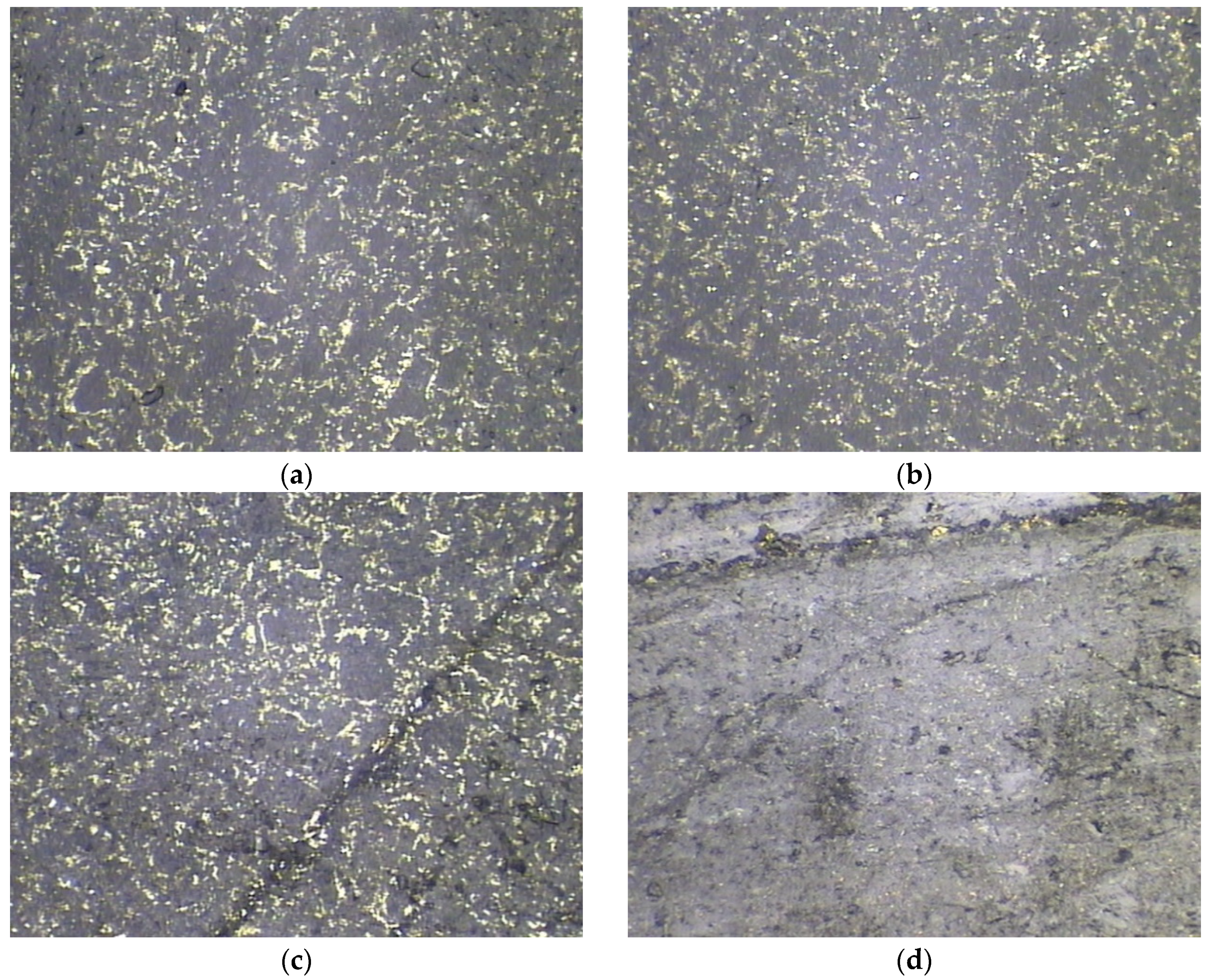
  • After 600 h of the service performance test, the sealing system, with the inlet direction the same as the spindle rotation and no slotting on the main sealing surface, operated stably. In addition, the auxiliary sealing surface did not have violent friction. The seal system could not work stably and was accompanied by smoke when the directions were opposite to one another. Through observation of the auxiliary sealing surface of the seal, there were obvious scratches and friction marks, the end face was obviously gray, and the copper-metal color faded.
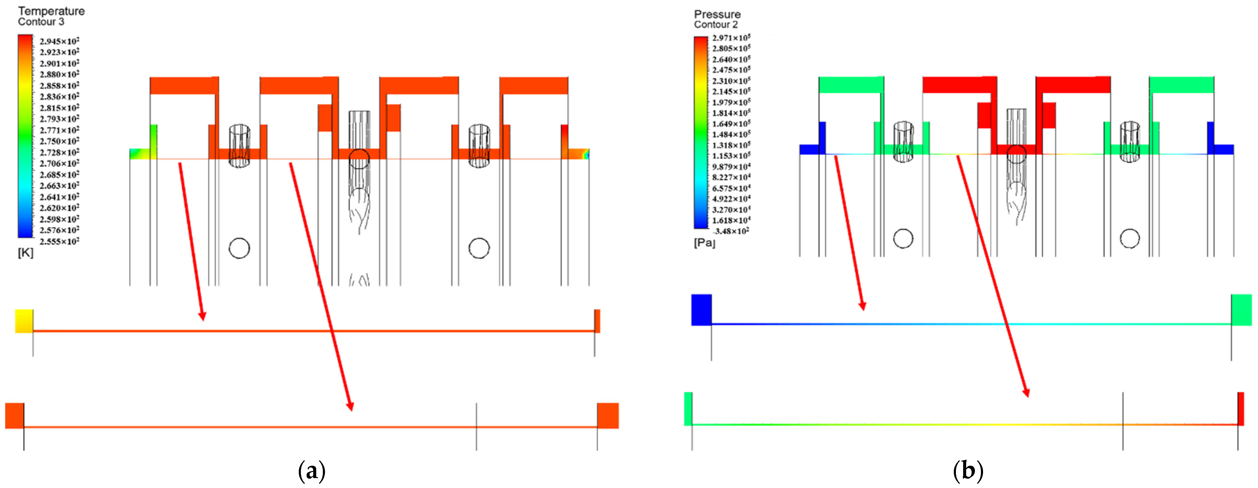
  • A full-size three-dimensional flow-field finite-element model was developed. When the floating ring is floating, the “inlet effect” has less influence on the leakage performance of the floating ring. The low-temperature zone is mainly concentrated in the dorsal cavity of the secondary float ring, which has less influence on the primary float ring. When the inlet direction is different to the spindle-rotation direction, the gas will flow irregularly in the intermediate cavity, so the auxiliary sealing surface of the floating ring cannot be tightened stably, which affects the stability of the sealing system.

Author Contributions

Conceptualization, Z.S., X.C. and S.L.; methodology, Z.S.; validation, Z.S., Z.L. and T.Z.; formal analysis, Z.S.; investigation, Z.S., X.C. and Z.L.; resources, S.L.; writing—original draft preparation, Z.S.; writing—review and editing, Z.S.; visualization, B.H.; supervision, S.L.; project administration, Z.S. All authors have read and agreed to the published version of the manuscript.

Funding

This research received no external funding.

Institutional Review Board Statement

Not applicable.

Informed Consent Statement

Not applicable.

Data Availability Statement

Not applicable.

Conflicts of Interest

The authors declare no conflict of interest.

References

  1. Ma, Y. Research on Opening Performance and Leakage Performance of Integral Gas Film Floating Ring Seal. Master’s Thesis, Beijing University of Chemical Technology, Beijing, China, 2020. [Google Scholar]
  2. Xia, P.; Chen, H.; Liu, Z.S.; Ma, W.S.; Yang, B.F. Analysis of whirling motion for the dynamic system of floating ring seal and rotor. Proc. Chin. Soc. Electr. Eng. 2019, 233, 1221–1235. [Google Scholar] [CrossRef]
  3. Zheng, R.; Chen, X.Z.; Li, S.X.; Zhao, X.; Shi, R.J.; Song, Z.F. Study on opening characteristics of high speed gas film inlaid floating ring seal. J. Beijing. Univ. Aeronaut. Astronaut. 2022, 48, 2111–2120. [Google Scholar]
  4. Ha, T.; Lee, Y.; Kim, C. Leakage and rotordynamic analysis of a high pressure floating ring seal in the turbo pump unit of a liquid rocket engine. Tribol. Int. 2002, 35, 153–161. [Google Scholar] [CrossRef]
  5. Ma, Y.; Wang, Q.F.; Shi, R.J.; Zhang, X.Y.; Li, Q.Z.; Li, S.X. Research on floating performance of aeroengine air film floating ring seal. Lubr. Oil 2021, 46, 38–44. [Google Scholar]
  6. Ma, Y.R.; Huo, W.H.; Liu, J.; Jiang, L.J.; Fang, Z.; Li, Z.G. Investigations on the leakage performance of wear failure and anti-rubbing structure design for a labyrinth seal. Chin. J. Turbomach. 2019, 61, 64–71. [Google Scholar]
  7. Arghir, M.; Tonon, D.; Dehouve, J. Analytic modeling of floating ring annular seals. J. Eng. Gas Turbine Power 2011, 134, 577–586. [Google Scholar] [CrossRef]
  8. Ma, R.M.; Zhao, X.; Li, S.X.; Chen, X.Z.; Yang, H.C. Experimental study on leakage characteristics of high speed gas split floating ring seal. Chin. J. Turbomach. 2020, 62, 75–81. [Google Scholar]
  9. Bae, J.-H.; Kwak, H.-D.; Heo, S.-J.; Choi, C.-H.; Choi, J.-S. Numerical and experimental study of nose for Lox floating ring seal in turbopump. Aerospace 2022, 9, 667. [Google Scholar] [CrossRef]
  10. Antoine, M.; Mihai, A.; Pierre, H.; Jerome, D. Experimental analysis of floating ring annular seals and comparisons with theoretical predictions. J. Eng. Gas Turb. Power 2015, 138, 042503. [Google Scholar]
  11. Shi, R.J. Temperature Field Analysis and Dynamic Performance Research of Inlaid Gas Film Floating Ring Seal. Master’s Thesis, Beijing University of Chemical Technology, Beijing, China, 2021. [Google Scholar]
  12. Shi, R.J.; Li, S.X.; Zheng, R.; Ma, L.J.; Zhang, J.B. Design method and research of high temperature gas floating ring seal with slightly variable gap. IOP Conf. Ser. Mater. Sci. Eng. 2021, 1081, 012005. [Google Scholar] [CrossRef]
  13. Li, G.Q.; Zhang, Q.; Huang, E.L.; Lei, Z.J.; Wu, H.W.; Xu, G. Leakage performance of floating ring seal in cold/hot state for aero-engine. Chin. J. Aeronaut. 2019, 32, 2085–2094. [Google Scholar] [CrossRef]
  14. Oike, M.; Nosaka, M.; Kikuchi, M.; Hasegawa, S. Two-phase flow in floating-ring seals for cryogenic turbopumps. Tribol. Trans. 1999, 42, 273–281. [Google Scholar] [CrossRef]
  15. He, C.H.; Xue, Z.H.; Liu, X.F.; Wang, T.Z. The rotor dynamic analysis of centrifugal pump rotor system. Chin. J. Turbomach. 2019, 61, 65–70. [Google Scholar]
  16. Xie, Y.N.; Hu, X.W.; Sun, Y.; Zhang, H. Effect of labyrinth seal on the stability of cantilever disk-hollow rotor and the improvement method. Chin. J. Turbomach. 2022, 64, 68–74. [Google Scholar]
  17. Choi, C.H.; Noh, J.G.; Kim, D.J.; Hong, S.S.; Kim, J. Effects of floating-ring seal clearance on the pump performance for turbopumps. J. Propul. Power 2009, 25, 191–195. [Google Scholar] [CrossRef]
  18. Balakh, L.Y.; Nikiforov, A.N. The reduction of the vibration level in high-speed rotor systems by means of floating seal rings. J. Mach. Manuf. Reliab. 2013, 42, 276–280. [Google Scholar] [CrossRef]
  19. Balakh, L.Y.; Barmina, O.V. The stability of rotation for a rotor with floating seal rings. J. Mach. Manuf. Reliab. 2015, 44, 114–119. [Google Scholar]
  20. Wang, J.X.; Li, S.X.; Ma, W.J.; Feng, R.P.; Liu, Z.W. Frictional heat analysis of bearing cavity ring-shaped floating ring seal. J. Mech. Electr. Eng. 2020, 37, 1032–1038. [Google Scholar]
Figure 1. Schematic diagram of a rocket’s liquid -fuel pump.
Machines 11 00373 g001
Figure 2. Two-dimensional diagram of the two-stage floating-ring isolation seal structure (1. seal outer cavity B, 2. seal inner cavity B, 3. gasket, 4. wave spring, 5. seal middle cavity A, 6. primary floating ring, 7. secondary floating ring, 8. seal inner cavity A, and 9. Seal outer cavity A).
Machines 11 00373 g002
Figure 3. The graphite ring’s appearance.
Machines 11 00373 g003
Figure 4. Floating-ring force analysis.
Machines 11 00373 g004
Figure 5. Fluid 3D model.
Machines 11 00373 g005
Figure 6. Fluid domain meshing.
Machines 11 00373 g006
Figure 7. Grid-independence verification.
Machines 11 00373 g007
Figure 8. Picture of the test bench.
Machines 11 00373 g008
Figure 9. Flow-line diagram in the middle chamber. (a) The air-inlet direction is the same as the spindle-rotation direction; (b) the air-inlet direction is opposite to the spindle rotation direction.
Machines 11 00373 g009
Figure 10. Finite-element analysis contour. (a) Temperature-field contour; (b) pressure-field contour.
Machines 11 00373 g010
Figure 11. Leakage-inlet pressure relationship. (a) Test-leakage curve; (b) finite-element and test leakage curve.
Machines 11 00373 g011
Figure 12. Surface appearance of the auxiliary sealing surface of the floating-ring test piece. (a) The air-inlet direction is the same as the spindle-rotation direction primary floating ring; (b) the air-inlet direction is the same as the spindle-rotation direction secondary floating ring; (c) the air-inlet direction is opposite to the spindle-rotation direction primary floating ring; (d) the air-inlet direction is opposite to the spindle-rotation direction secondary floating ring.
Machines 11 00373 g012
Table 1. Floating-ring gas-isolation seal assembly design conditions.
MediaTemperature/KPressure/MPaRotational Speed/rpm
Liquid oxygen sideLiquid oxygen90015,000–35,000
Liquid methane sideLiquid methane1130
Isolated gasHelium2980.5
Table 2. Floating ring gas isolation seal assembly materials.
NumberNameMaterial
1Sealing chamberS30408
2Graphite ringM120P
3GasketPTFE
4Wave springS304
Table 3. Interpretation of nozzle.
Nozzle DesignatorNozzle NameNozzle
A1–4Isolated gas inletChanges the isolation gas inlet pressure
B1–6/C1–6Primary outletLeakage channel after primary floating ring
D1–4/E1–4Secondary outletLeakage channel after secondary floating ring
Table 4. Boundary conditions.
NameBoundary ConditionNumerical Value
Inlet A1–4Pressure-inlet0.25–0.5 MPa 298 K
Outlet (liquid oxygen side)Pressure-outlet0 MPa 90 K
Outlet (liquid methane side)Pressure-outlet0 MPa 113 K
RunwayMoving wall6000–20,000 rpm
Disclaimer/Publisher’s Note: The statements, opinions and data contained in all publications are solely those of the individual author(s) and contributor(s) and not of MDPI and/or the editor(s). MDPI and/or the editor(s) disclaim responsibility for any injury to people or property resulting from any ideas, methods, instructions or products referred to in the content.

