
Modeling and Optimization of Surface Integrity and Sliding Wear Resistance of Diamond-Burnished Holes in Austenitic Stainless Steel Cylinder Lines
 , , , ,
Abstract
:1. Introduction
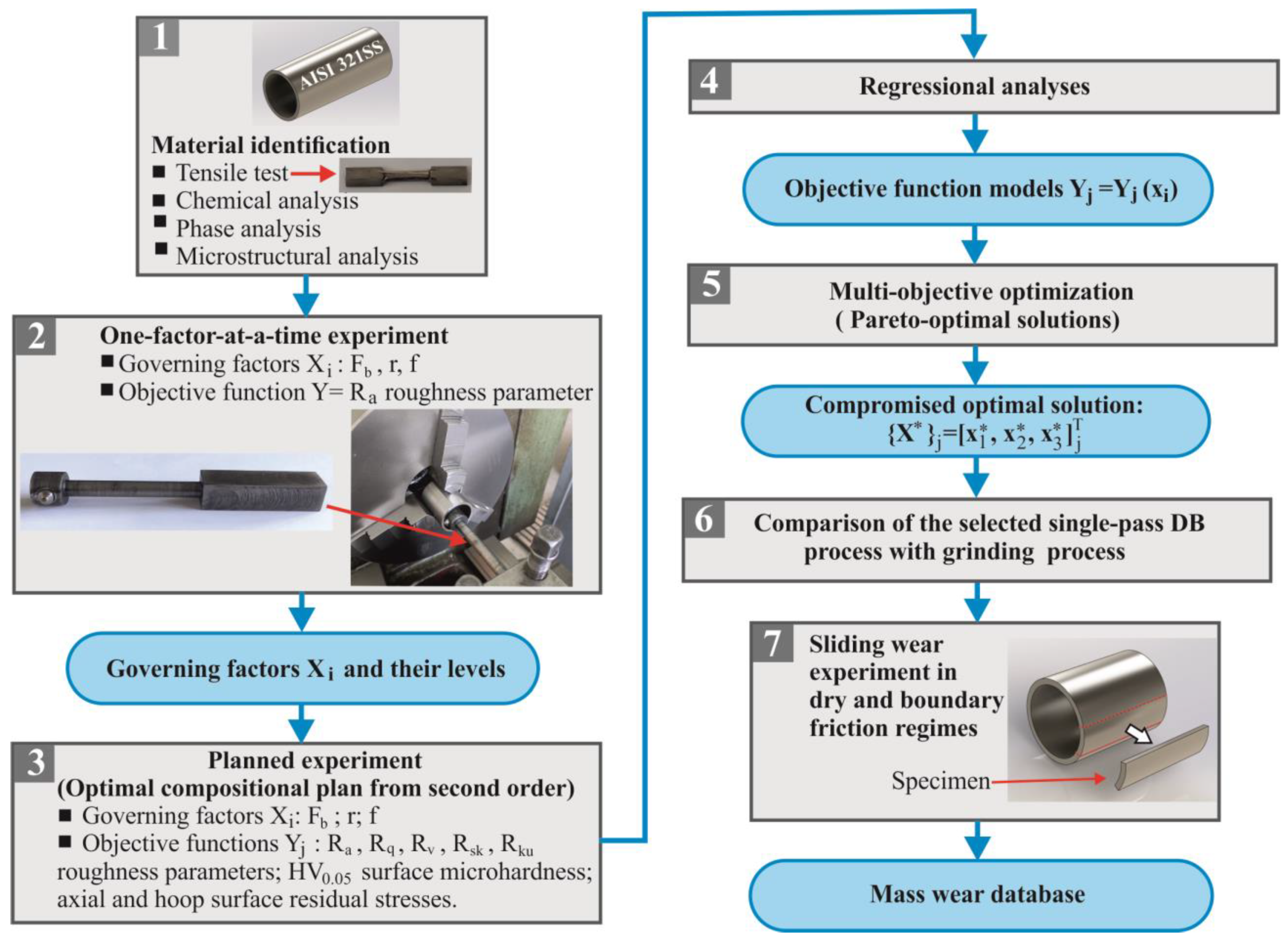
2. Materials and Methods
- Before friction, the specimen’s initial mass was measured with an accuracy of by means of a WPS 180/C/2 electronic balance. To prevent electrostatic effects, each specimen was cleaned with ethyl alcohol to remove mechanical and organic particles.
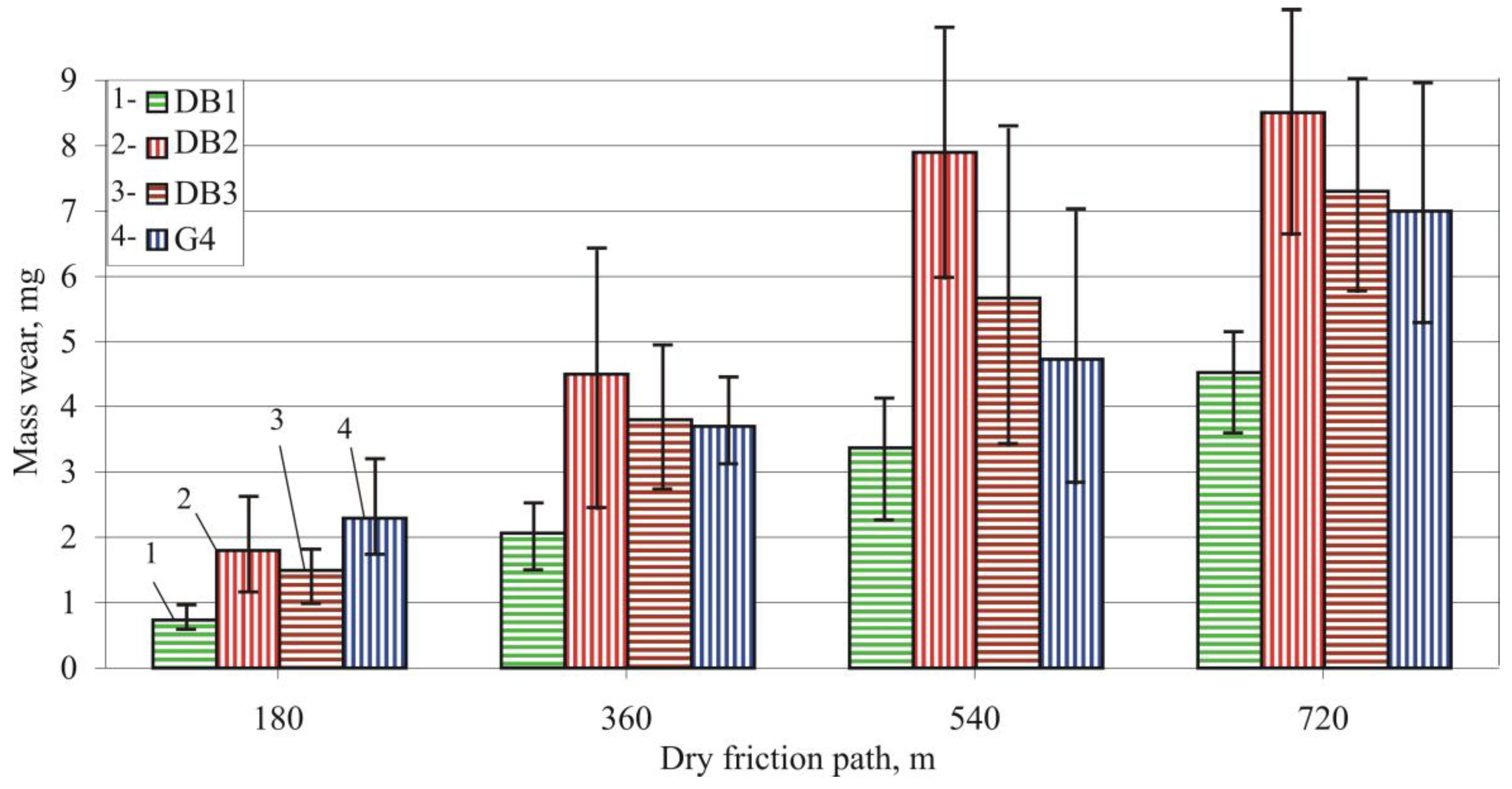
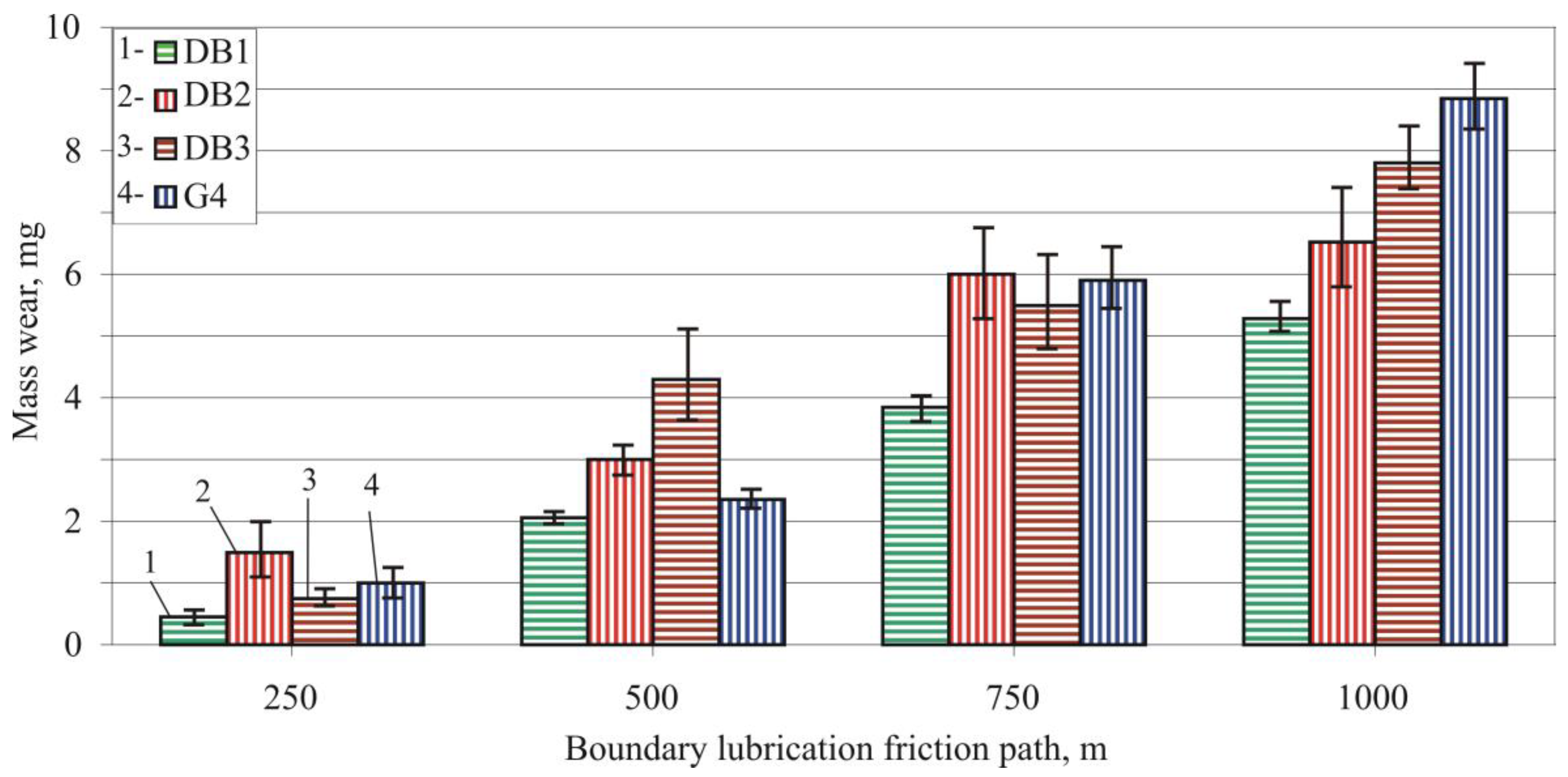
- The specimen mass was measured for a set friction path . The mass wear was calculated with the formula: .
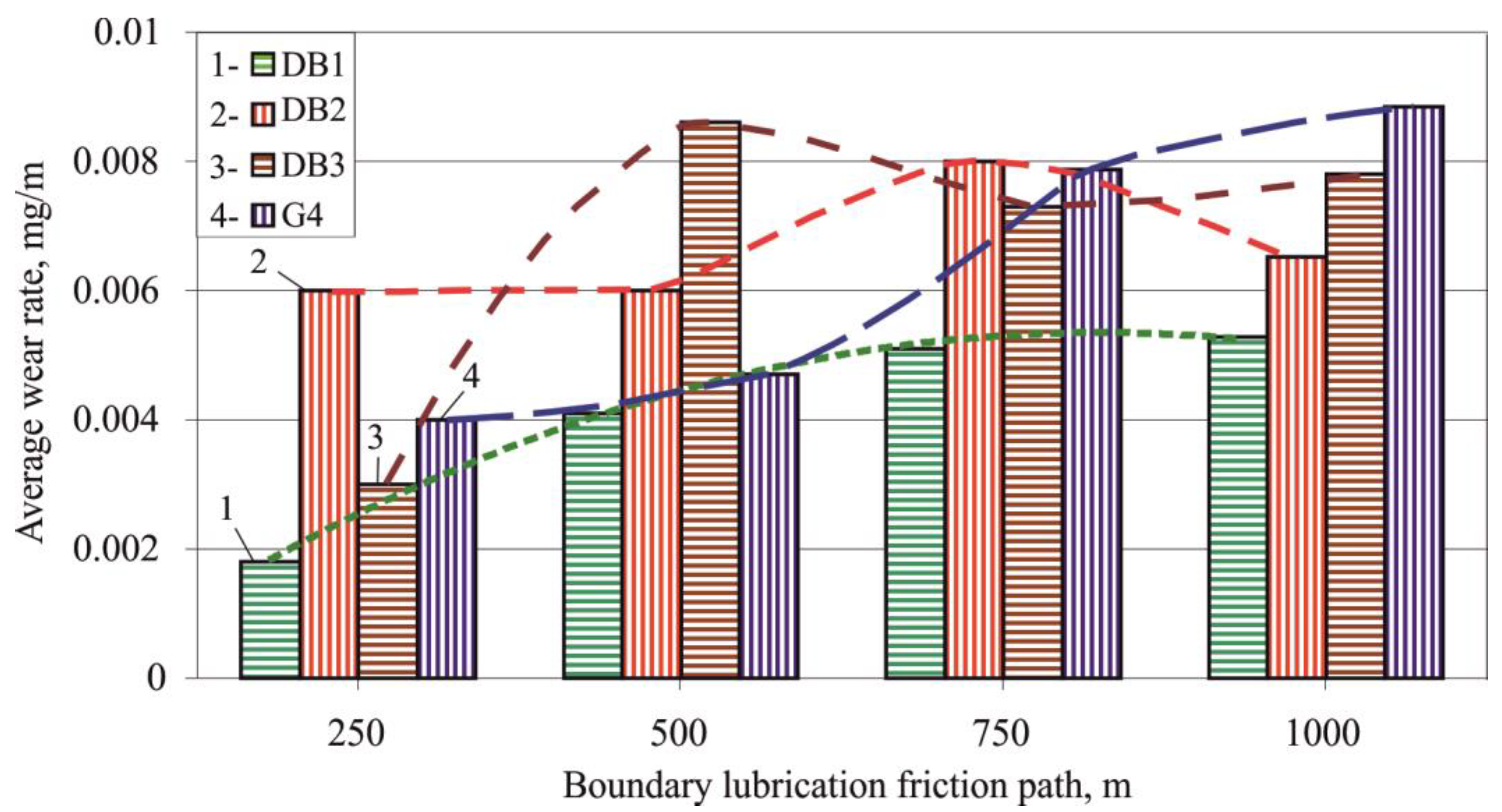
- The average wear rate was calculated with the formula .
3. Results and Discussion
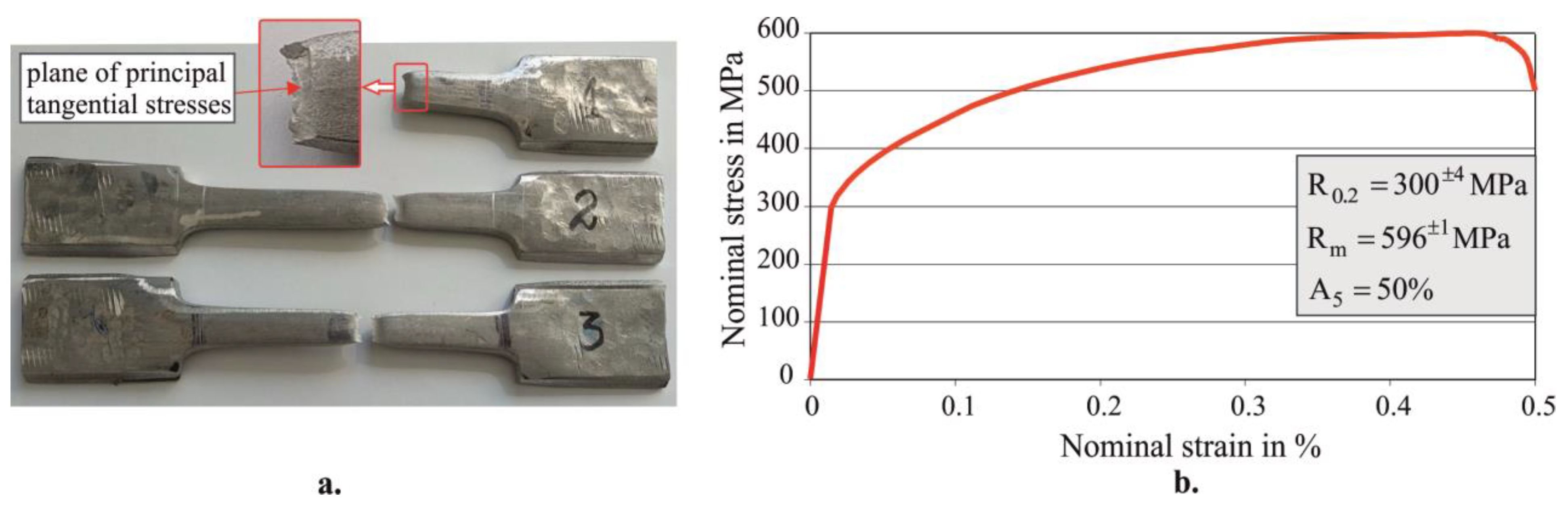
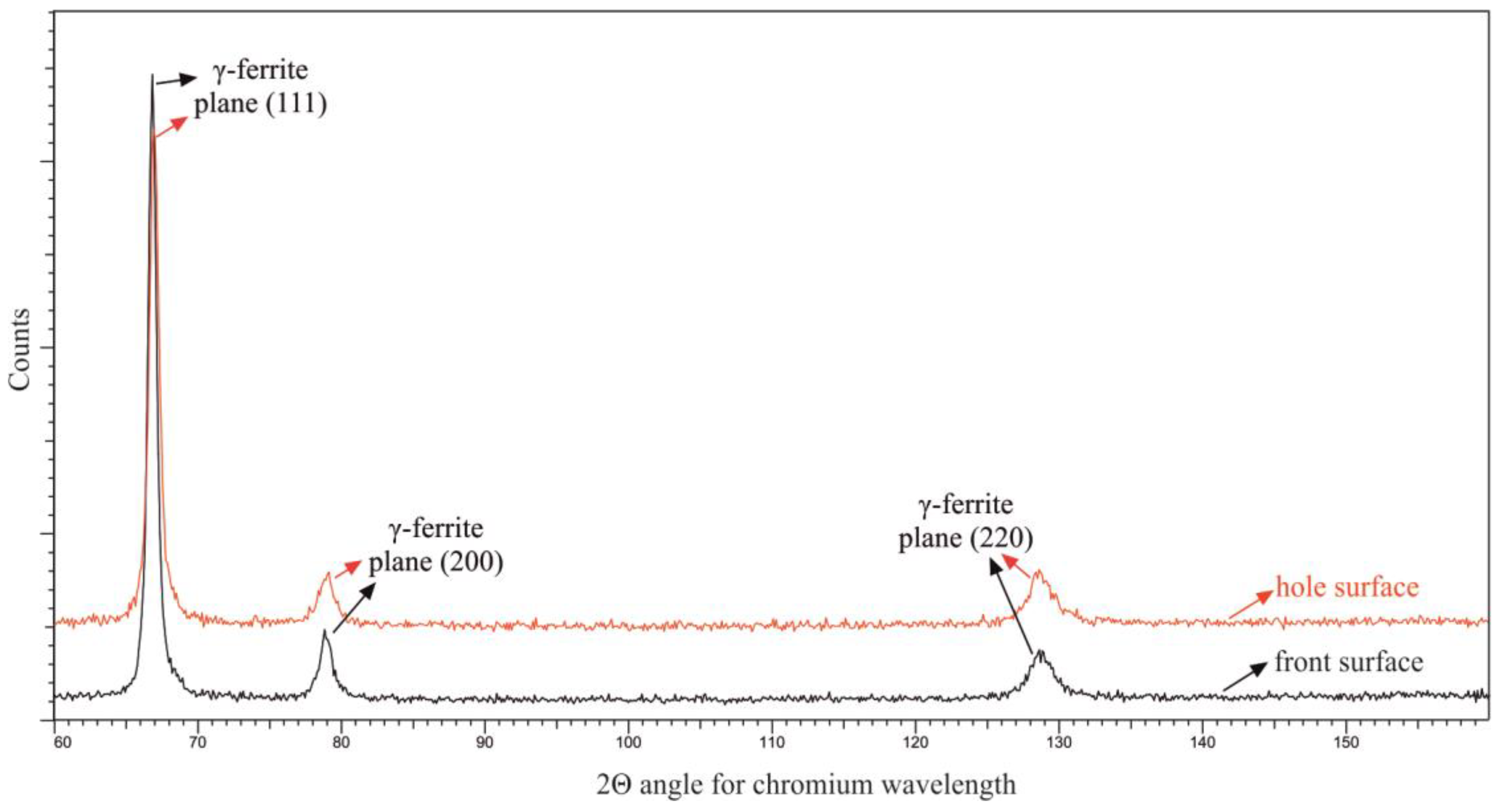
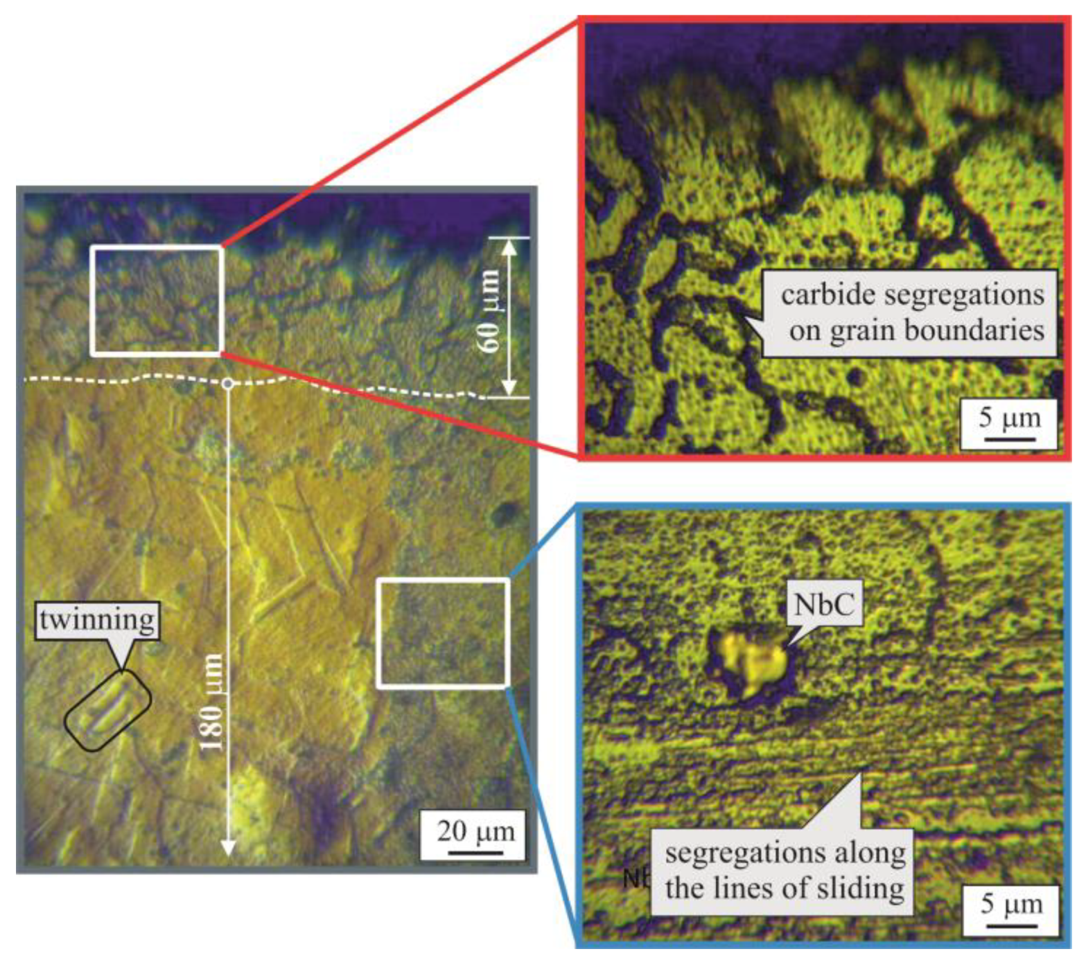
3.1. Chemical Composition, Main Mechanical Characteristics, and Initial Microstructure
3.2. Effect of DB on the Surface Roughness Ra Height Parameter: One-Factor-at-a-Time Method
3.2.1. Influence of the Burnishing Force and Diamond Insert Radius
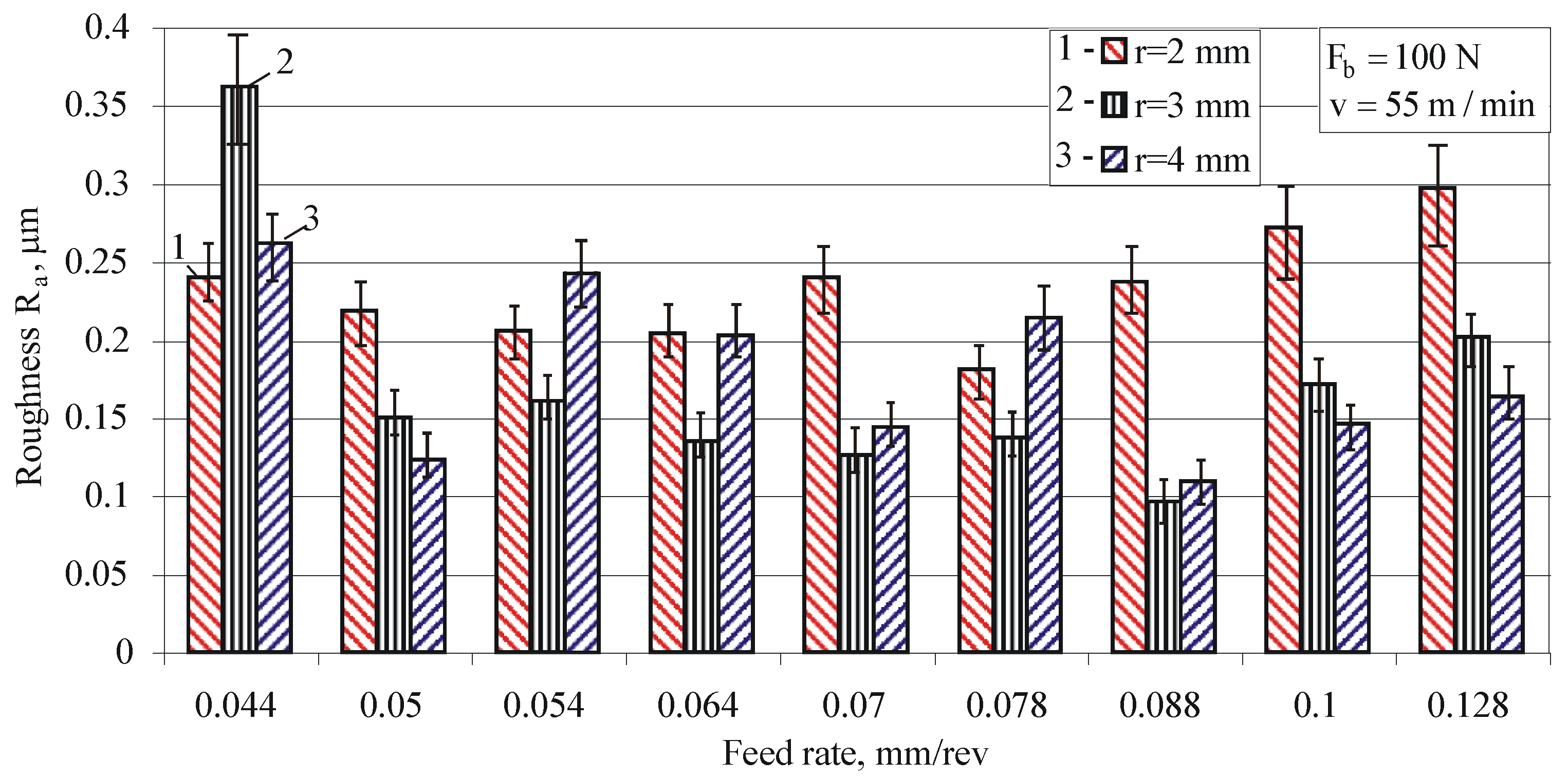
3.2.2. Influence of the Feed Rate for Different Radius Values
3.3. Effect of DB on the Surface Integrity: Planned Experiment and Optimization
3.4. Reciprocating Sliding Wear Resistance of the Treated Surfaces
3.4.1. Specimen Treatments and Designations
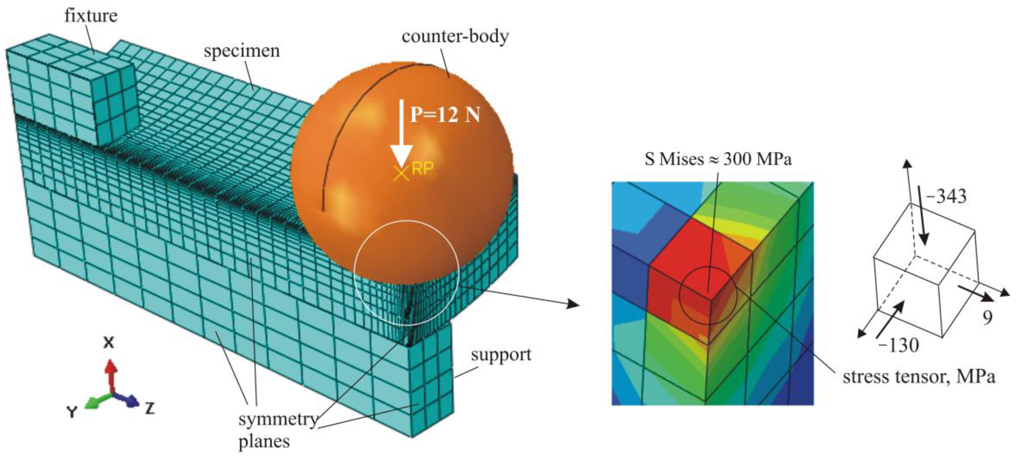
3.4.2. Reciprocating Sliding Wear Tests
4. Conclusions
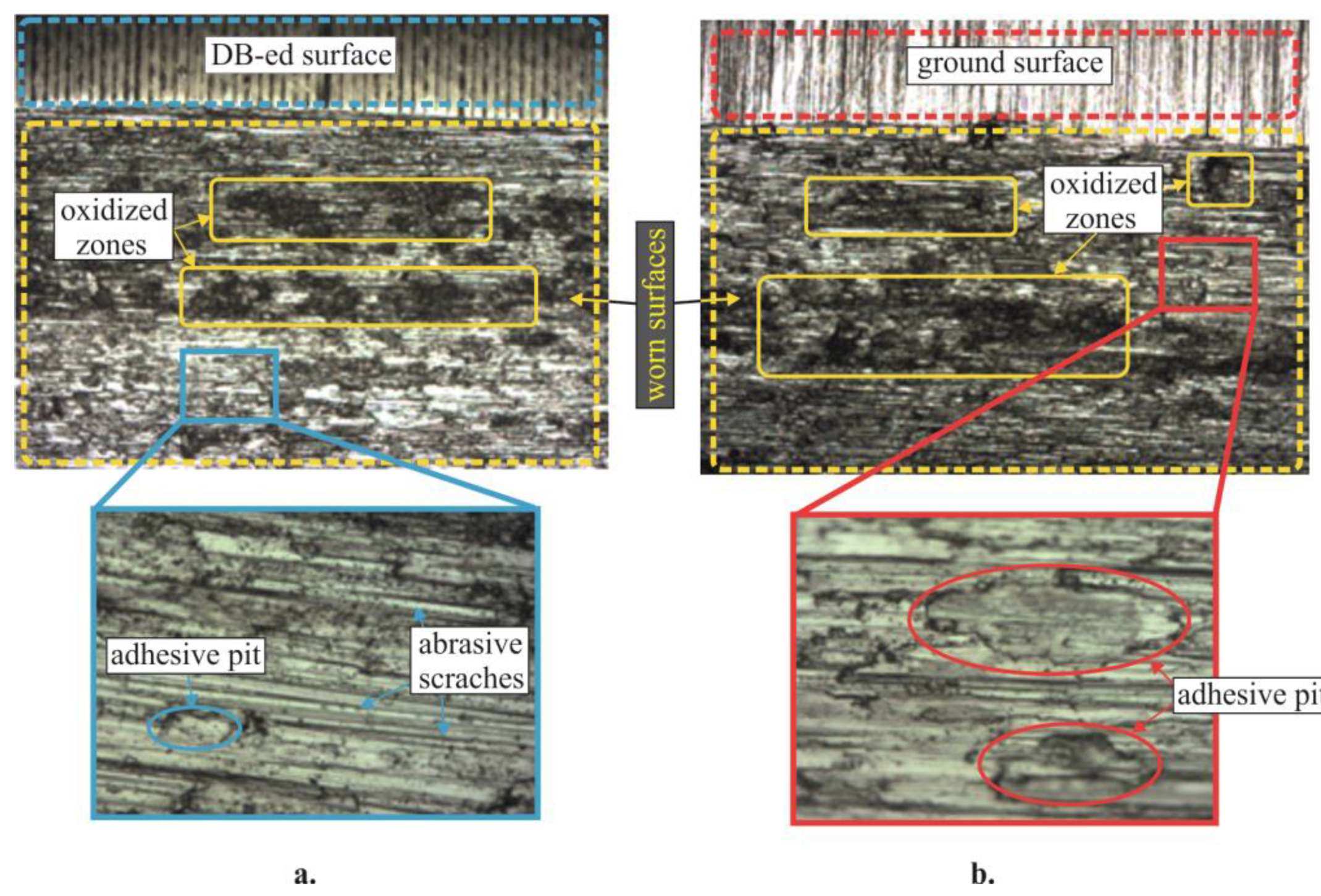
- The DB of holes in AISI 321 SS, performed with a diamond insert radius , burnishing force , and feed rate , significantly improves wear resistance. This optimal DB process maximizes the reciprocating sliding wear resistance of the hole surface in both dry friction and boundary lubrication friction modes.
- The wear rate trend line for sample holes processed with the optimal DB process decreased at the end of the friction path under both friction modes. The wear rate trend line for ground samples showed an opposite trend for both modes of friction. These experimental results show that to minimize the wear of holes in AISI 321 SS, a more pronounced cold work effect and minimum values of the roughness amplitude parameters are required.
- The developed DB device with elastic beam is applicable for holes with a wide range of variation in their diameters.
Author Contributions
Funding
Data Availability Statement
Conflicts of Interest
References
- Dwivedi, D.K. Surface Engineering. In Enhancing Life of Tribological Components; Springer: New Delhi, India, 2018; ISBN 978-81-322-3779-2. [Google Scholar]
- Biboulet, N.; Bouassida, H.; Lubrecht, A.A. Cross hatched texture influence on the load carrying capacity of oil control rings. Tribol. Int. 2015, 82, 12–19. [Google Scholar] [CrossRef]
- Pawlus, P. Effects of honed cylinder surface topography on the wear of piston-piston ring-cylinder assemblies under artificially increased dustiness conditions. Tribol. Int. 1993, 26, 49–55. [Google Scholar] [CrossRef]
- Ecoroll Catalogue. Tools and Solutions for Metal Surface Improvement; Ecoroll Corporation Tool Technology: Milford, OH, USA, 2006. [Google Scholar]
- Maximov, J.T.; Duncheva, G.V.; Anchev, A.P.; Ichkova, M.D. Slide burnishing—Review and prospects. Int. J. Adv. Manuf. Technol. 2019, 104, 785–801. [Google Scholar] [CrossRef]
- Akkurt, A.; Kurt, A.; Özdemir, A.; Şeker, U. Comparison of hole surface finishing processes with roller burnishing method applied in copper materials. Gazi Univ. J. Sci. 2014, 27, 721–734. [Google Scholar]
- Przybylski, W. Sliding burnishing technology of holes in hardened steel. Adv. Manuf. Sci. Technol. 2016, 40, 43–51. [Google Scholar]
- Korzynski, M. Relief making on bearing sleeve surface by eccentric burnishing. J. Mater. Process. Technol. 2009, 209, 131–138. [Google Scholar] [CrossRef]
- Maximov, J.T.; Duncheva, G.V.; Anchev, A.P.; Dunchev, V.P. Crack resistance enhancement of joint bar holes by slide diamond burnishing using new tool equipment. Int. J. Adv. Manuf. Technol. 2019, 102, 3151–3164. [Google Scholar] [CrossRef]
- Pa, P.S. Continuous finishing processes using a combination of burnishing and electrochemical finishing on bore surface. Int. J. Adv. Manuf. Technol. 2010, 49, 147–154. [Google Scholar] [CrossRef]
- Duncheva, G.; Maximov, J.; Anchev, A.; Dunchev, V.; Argirov, Y.; Kandeva-Ivanova, M. Enhancement of the wear resistance of CuAl9Fe4 sliding bearing bushings via diamond burnishing. Wear 2022, 510, 204491. [Google Scholar] [CrossRef]
- Korzynski, M.; Dudek, K.; Korzynska, K. Effect of Slide Diamond Burnishing on the Surface Layer of Valve Stems and the Durability of the Stem-Graphite Seal Friction Pair. Appl. Sci. 2023, 13, 6392. [Google Scholar] [CrossRef]
- Pawlus, P.; Reizer, R.; Wieczorowski, M. Functional Importance of Surface Texture Parameters. Materials 2021, 14, 5326. [Google Scholar] [CrossRef]
- Willis, E. Surface finish in relation to cylinder liners. Wear 1986, 109, 351–366. [Google Scholar] [CrossRef]
- Willn, E. Characterisation of cylinder bore surface finish—A review of profile analyiss. Wear 1972, 19, 143–162. [Google Scholar] [CrossRef]
- Brinkman, S.; Bodschwinna, H. Characterisation of automotive bore performance using 3D surface metrology. In Advanced Techniques for Assessment Surface Topography; Blunt, L., Jiang, X., Eds.; Kogan Page Science: London, UK, 2003; pp. 307–347. [Google Scholar]
- Grabon, W.; Pawlus, P.; Wos, S.; Koszela, W.; Wieczorowski, M. Effects of cylinder liner surface topography on friction and wear of liner-ring system at low temperature. Tribol. Int. 2018, 121, 148–160. [Google Scholar] [CrossRef]
- Pawlus, P. Change of cylinder surface topography in the initial stage of engine life. Wear 1997, 209, 69–83. [Google Scholar] [CrossRef]
- Butler, D.L.; Blunt, L.A.; O’Connor, R.F.; Stout, K.J. The characterisation of cylinder liner bore polishing with 3-dimensional functional indices. In Proceedings of the 7th International Conference on Metrology and Properties of Engineering Surfaces, Gothenburg, Sweden, 2–4 April 1997; pp. 517–529. [Google Scholar]
- Dong, P.; Davis, E.J.; Butler, D.L.; Stout, K.J. Topographic features of cylinder liners—An application of three-dimensional characterisation technique. Tribol. Int. 1995, 28, 453–463. [Google Scholar] [CrossRef]
- Abe, Y.; Daodon, W.; Takahashi, N.; Mori, K. Improvement of seizure resistance by roughening surface of stainless steel drawn cup in ironing using die having lubricant pocket. Prod. Eng. 2016, 10, 551–562. [Google Scholar] [CrossRef]
- Sedlacek, M.; Podgornik, B.; Vizintin, J. Correlation between standard roughness parameters skewness and kurtosis and tribological behaviour of contact surface. Tribol. Int. 2012, 48, 102–112. [Google Scholar] [CrossRef]
- Zabala, A.; Blunt, L.; Tato, W.; Aginagalde, A.; Gomez, X.; Llavori, I. The use of areal surface topography characterisation in relation to fatigue performance. In MATEC Web of Conferences; EDP Sciences: Les Ulis, France, 2018; Volume 165, p. 14013. [Google Scholar]
- Korzynski, M.; Dudek, K.; Kruczek, B.; Kocurek, P. Equilibrium surface texture of valve stems and burnishing method to obtain it. Tribol. Int. 2018, 124, 195–199. [Google Scholar] [CrossRef]
- Belhadjamor, M.; Belghith, S.; Mezlini, S.; El Mansori, M. Numerical study of normal contact stiffness, non-Gaussian roughness and elastic contact behaviour. Proc. Inst. Mech. Eng. Part J J. Eng. Tribol. 2020, 234, 1368–1380. [Google Scholar] [CrossRef]
- Zhan, W.; Huang, P. Modeling tangential contact based on non-Gaussian rough surfaces. Proc. Inst. Mech. Eng. Part J J. Eng. Tribol. 2019, 233, 51–60. [Google Scholar] [CrossRef]
- Dzierwa, A.; Pawlus, P.; Zelasko, W. The influence of disc surface topography after vapour blasting on friction and wear of sliding pairs under dry friction conditions. Coatings 2020, 10, 102. [Google Scholar] [CrossRef]
- Chang, L.; Jeng, Y.-R. Effects of negative skewness of surface roughness on the contact and lubrication of nominally flat metallic surfaces. Proc. Inst. Mech. Eng. Part J J. Eng. Tribol. 2012, 227, 559–569. [Google Scholar] [CrossRef]
- Dzierwa, A. Influence of surface preparation on surface topography and tribological behaviours. Arch. Civ. Mech. Eng. 2017, 17, 502–510. [Google Scholar] [CrossRef]
- Swirad, S.; Wydrzynski, D.; Niesłony, P.; Krolczyk, G.M. Influence of hydrostatic burnishing strategy on the surface topography of martensitic steel. Measurement 2019, 138, 590–601. [Google Scholar] [CrossRef]
- Pettersson, U.; Jacobson, S. Friction and wear properties of micro textured DLC coated surfaces in boundary lubricated sliding. Tribol. Lett. 2004, 17, 553–559. [Google Scholar] [CrossRef]
- Yuan, S.; Huang, W.; Wang, X. Orientation effects of micro-grooves on sliding surfaces. Tribol. Int. 2011, 44, 1047–1054. [Google Scholar] [CrossRef]
- DIFFRAC. DQUANT. Quantitative Analysis from Calibration to Reporting; Bruker AXS GmbH: Karlsrue, Germany, 2018. [Google Scholar]
- Vuchkov, I.N.; Vuchkov, I.I. QStatLab Professional, v. 5.5—Statistical Quality Control Software; User’s Manual: Sofia, Bulgaria, 2009.
- Deb, K.; Pratap, A.; Agarwal, S.; Meyarivan, T. A fast and elitist multiobjective genetic algorithm: NSGA-II. IEEE Trans. Evol. Comput. 2002, 6, 182–197. [Google Scholar] [CrossRef]


| Fe | C | Si | Mn | P | S | Cr | Ni | Ti | Nb | Mo | Cu | Co | V | Others |
|---|---|---|---|---|---|---|---|---|---|---|---|---|---|---|
| 69.1 | 0.023 | 0.286 | 1.92 | 0.04 | 0.027 | 17.7 | 9.35 | 0.538 | 0.058 | 0.27 | 0.353 | 0.103 | 0.102 | balance |
| Governing Factors | Levels | |||||||
|---|---|---|---|---|---|---|---|---|
| Natural | Codded | Natural | Coded | |||||
| Diamond radius, mm | x1 | 2 | 3 | 4 | −1 | 0 | 1 | |
| Burnishing force, N | 80 | 160 | 240 | |||||
| Feed rate, mm/rev | 0.05 | 0.075 | 0.1 | |||||
| Exp. Point | , μm | , μm | , μm | , μm | , μm | , μm | |||||
|---|---|---|---|---|---|---|---|---|---|---|---|
| 1 | −1 | −1 | −1 | 0.266 | 0.2621 | 0.319 | 0.3134 | 0.595 | 0.5579 | 0.104 | 0.1060 |
| 2 | 1 | −1 | −1 | 0.175 | 0.1853 | 0.245 | 0.2560 | 0.825 | 0.8849 | −0.468 | −0.5498 |
| 3 | −1 | 1 | −1 | 0.252 | 0.2432 | 0.299 | 0.2943 | 0.667 | 0.7122 | 0.070 | 0.0824 |
| 4 | 1 | 1 | −1 | 0.071 | 0.055 | 0.094 | 0.0703 | 0.400 | 0.3852 | −0.489 | −0.5734 |
| 5 | −1 | −1 | 1 | 0.189 | 0.1958 | 0.232 | 0.2401 | 0.742 | 0.8204 | −0.322 | −0.3822 |
| 6 | 1 | −1 | 1 | 0.252 | 0.2516 | 0.340 | 0.3292 | 1.249 | 1.1474 | −1.136 | −1.0380 |
| 7 | −1 | 1 | 1 | 0.178 | 0.1769 | 0.219 | 0.2210 | 0.446 | 0.4497 | 0.530 | 0.5706 |
| 8 | 1 | 1 | 1 | 0.108 | 0.1212 | 0.125 | 0.1436 | 0.142 | 0.1227 | −0.090 | −0.0852 |
| 9 | −1 | 0 | 0 | 0.119 | 0.1376 | 0.157 | 0.1644 | 0.296 | 0.2863 | 0.089 | 0.0942 |
| 10 | 1 | 0 | 0 | 0.067 | 0.0714 | 0.085 | 0.0970 | 0.291 | 0.2863 | −0.625 | −0.5616 |
| 11 | 0 | −1 | 0 | 0.166 | 0.1418 | 0.197 | 0.1819 | 0.801 | 0.8158 | −0.872 | −0.9135 |
| 12 | 0 | 1 | 0 | 0.066 | 0.0672 | 0.084 | 0.0795 | 0.381 | 0.3806 | −0.392 | −0.4489 |
| 13 | 0 | 0 | −1 | 0.169 | 0.1864 | 0.220 | 0.2335 | 0.889 | 0.9468 | −0.797 | −0.6812 |
| 14 | 0 | 0 | 1 | 0.204 | 0.1864 | 0.242 | 0.2335 | 1.019 | 0.9468 | −0.664 | −0.6812 |
| Exp. point | Hv | Hv scattering | MPa | meas. error, MPa | , MPa | MPa | meas. error, MPa | , MPa | |||
| 1 | 2.817 | 2.8816 | 467 | 24.5 | 470.67 | −428.5 | 50.3 | −454.7 | −79.1 | 25.5 | −53.6 |
| 2 | 4.571 | 4.7756 | 457 | 31 | 464.32 | −244.0 | 59.7 | −251.6 | 19.2 | 20.8 | −9.4 |
| 3 | 2.213 | 2.0266 | 490 | 43 | 494.92 | −431.5 | 57.1 | −436.8 | 117.3 | 76.9 | 119.4 |
| 4 | 3.651 | 3.9206 | 441 | 21 | 440.07 | −325.8 | 62.8 | −305.7 | 82.9 | 39.4 | 101.4 |
| 5 | 2.737 | 2.8816 | 451 | 38 | 451.47 | −415.9 | 37.4 | −435.9 | −29.0 | 44.5 | −46.5 |
| 6 | 5.271 | 4.7756 | 452 | 24.5 | 445.12 | −155.7 | 50.4 | −150.3 | 101.7 | 48 | 100.4 |
| 7 | 2.165 | 2.0266 | 481 | 26.5 | 475.72 | −489.5 | 83.8 | −481.9 | −20.1 | 60.8 | 9.5 |
| 8 | 3.693 | 3.9206 | 424 | 37 | 420.87 | −294.4 | 61 | −268.2 | 118.8 | 59 | 94.3 |
| 9 | 2.950 | 3.16.72 | 477 | 26 | 473.20 | −577.0 | 38.3 | −532.9 | 28.5 | 61.7 | −11.2 |
| 10 | 5.166 | 5.0612 | 439 | 36 | 442.60 | −280.5 | 30.7 | −324.5 | 17.4 | 46.7 | 53.2 |
| 11 | 3.747 | 3.8286 | 410 | 36.5 | 410.25 | −198.0 | 78.7 | −149.4 | −0.6 | 32.4 | 21.3 |
| 12 | 3.146 | 2.9736 | 400 | 39.5 | 410.25 | −151.0 | 50.2 | −199.5 | 130.7 | 39.7 | 104.8 |
| 13 | 4.340 | 4.1142 | 440 | 27 | 419.85 | −197.0 | 28 | −177.9 | 63.6 | 21.8 | 44.6 |
| 14 | 4.001 | 4.1142 | 391 | 43 | 400.65 | −130.7 | 67.7 | −149.7 | 21.9 | 35.6 | 44.6 |
| 0.1045 | −0.0331 | −0.0373 | 0 | 0 | 0 | 0.0819 | −0.0279 | 0.03312 | 0 | |
| 0.13075 | −0.0337 | −0.0512 | 0 | 0 | 0 | 0.10275 | −0.0416 | 0.03662 | 0 | |
| 0.59815 | 0 | −0.2176 | 0 | −0.3118 | 0 | 0.34869 | −0.1635 | 0 | −0.1312 | |
| −0.6812 | −0.3279 | 0.2323 | 0 | 0.4475 | 0 | 0 | 0 | 0 | 0.2441 | |
| 4.11425 | 0.947 | −0.4275 | 0 | 0 | −0.7131 | 0 | 0 | 0 | 0 | |
| 410.25 | −15.3 | 0 | −9.6 | 47.65 | 0 | 0 | −12.125 | 0 | 0 | |
| −209.47 | 104.2 | −25.01 | 14.06 | −219.28 | 34.9687 | 45.6187 | −17.987 | 20.637 | −15.937 | |
| 44.6846 | 32.24 | 41.74 | 0 | −23.669 | 18.4308 | 0 | −15.562 | 25.7125 | −29.262 |
| № | f, mm/tr | , μm | , μm | , μm | HV | MPa | MPa | ||||
|---|---|---|---|---|---|---|---|---|---|---|---|
| 1 | 2 | 80 | 0.088 | 0.163 | 0.197 | 0.601 | −0.314 | 2.893 | 453.8 | 46.8 | −458.9 |
| 2 | 3 | 221 | 0.078 | 0.077 | 0.093 | 0.426 | −0.485 | 3.372 | 409.3 | −84.9 | −207.7 |
| 3 | 4 | 218 | 0.054 | 0.057 | 0.0752 | 0.355 | −0.549 | 4.379 | 408.3 | 77.9 | −321.5 |
| Group № | Finishing | , μm | , μm | , μm | HV | MPa | MPa | ||
|---|---|---|---|---|---|---|---|---|---|
| 1 | DB with r = 2 mm | 0.228 | 0.304 | 0.891 | −0.193 | 3.574 | 470.1 | 26.2 | −588.1 |
| 2 | DB with r = 3 mm | 0.147 | 0.197 | 0.769 | −0.870 | 5.088 | 425.7 | −80.3 | −178.3 |
| 3 | DB with r = 4 mm | 0.102 | 0.125 | 0.286 | −0.010 | 2.640 | 420.9 | 88.3 | −420.3 |
| 4 | grinding | 0.387 | 0.351 | 2.262 | −1.442 | 5.633 | 417.9 | 46.1 | −329.7 |
Disclaimer/Publisher’s Note: The statements, opinions and data contained in all publications are solely those of the individual author(s) and contributor(s) and not of MDPI and/or the editor(s). MDPI and/or the editor(s) disclaim responsibility for any injury to people or property resulting from any ideas, methods, instructions or products referred to in the content. |
© 2023 by the authors. Licensee MDPI, Basel, Switzerland. This article is an open access article distributed under the terms and conditions of the Creative Commons Attribution (CC BY) license (https://creativecommons.org/licenses/by/4.0/).
Share and Cite
Duncheva, G.; Maximov, J.; Anchev, A.; Dunchev, V.; Argirov, Y.; Velkov, S. Modeling and Optimization of Surface Integrity and Sliding Wear Resistance of Diamond-Burnished Holes in Austenitic Stainless Steel Cylinder Lines. Machines 2023, 11, 872. https://doi.org/10.3390/machines11090872
Duncheva G, Maximov J, Anchev A, Dunchev V, Argirov Y, Velkov S. Modeling and Optimization of Surface Integrity and Sliding Wear Resistance of Diamond-Burnished Holes in Austenitic Stainless Steel Cylinder Lines. Machines. 2023; 11(9):872. https://doi.org/10.3390/machines11090872
Chicago/Turabian StyleDuncheva, Galya, Jordan Maximov, Angel Anchev, Vladimir Dunchev, Yaroslav Argirov, and Svetlozar Velkov. 2023. "Modeling and Optimization of Surface Integrity and Sliding Wear Resistance of Diamond-Burnished Holes in Austenitic Stainless Steel Cylinder Lines" Machines 11, no. 9: 872. https://doi.org/10.3390/machines11090872