
Sustainable Energy Harvesting Mechanism with Flow-Induced Vibration

1
College of Aviation, Embry-Riddle Aeronautical University, Daytona Beach, FL 32114, USA
2
Faculty of Materials and Manufacturing, Beijing University of Technology, Beijing 100124, China
3
College of Engineering, Virginia Polytechnic Institute and State University, Blacksburg, VA 24061, USA
4
Electrical and Computer Engineering Department, University of West Florida, Pensacola, FL 32514, USA
*
Author to whom correspondence should be addressed.
Machines 2023, 11(9), 902; https://doi.org/10.3390/machines11090902
Submission received: 16 August 2023
/
Revised: 1 September 2023
/
Accepted: 7 September 2023
/
Published: 11 September 2023
(This article belongs to the Section Electromechanical Energy Conversion Systems)
Abstract
:This study investigates the feasibility of utilizing a flow-induced vibration actuator as a potential energy source using piezoelectric energy harvesting. The focus is on exploring the behavior of piezo films configured as cantilever beams subjected to flow-induced vibration, which can be induced with fluid or wind streams. The primary objective is to maximize the harvested energy from the vibrating structure. This paper develops theoretical models to analyze the resonant frequencies and energy-harvesting potential of the piezo films in the context of flow-induced vibration. Experimental validations are conducted to verify the theoretical predictions. The findings indicate that higher operating frequencies in the second mode offer improved energy harvesting efficiency compared with lower modes. With the strategic adjustment of resonant frequencies using attached masses on individual piezo films, the harvestable energy output of a single film can be significantly increased from less than 1 μW to approximately 18 μW. However, the phase differences among individual piezo films can impact frequency measurements, necessitating careful fine-tuning of the physical conditions of individual components. To optimize energy harvesting, this study emphasizes the importance of implementing efficient charging mechanisms. By identifying suitable environmental vibration sources, the required charging duration for a synthesized energy harvesting array can be reduced by 25% as well. Despite certain challenges, such as phase deviations and turbulence, this study demonstrates the promising potential of flow-induced vibration resonators as sustainable energy sources. This work lays the foundation for further advancements in energy harvesting technology, offering environmentally friendly and renewable energy solutions.
1. Introduction
A sustainable power source is always an important issue for sensor devices used in remote locations for continuous monitoring of unattended inspections. However, most of the current solutions are limited by various constraints of climatic conditions, insufficient harvestable energy sources, and various environmental limits. To address these challenges, energy-harvesting devices that harvest kinetic energy from the surrounding environment have become an important research topic, as they can serve as power sources for remote sensing devices that traditional renewable energy cannot power. Among various types of materials, the development and characterization of piezoelectric materials for harvesting ambient power sources has become a major research area due to the key role they play in terms of device efficiency. In the past decade, lead zirconated titanite (PZT) has been extensively studied, and its brittle response to externally applied mechanical strain(s) [1] was identified as a major disadvantage. An interesting way to address this challenge is by aligning and laminating PZT fibers—of various lengths ranging between 15 and 250 μm—in epoxy matrices to induce mechanical flexibility [2]. Beyond PZT, polymer-based flexible devices based on polyvinylidene fluoride (PVDF) were shown to exhibit enhanced mechanical flexibility and performance compared with piezoceramic-based systems [3,4]. Lee et al. [5] proposed the use of ZnO and AlN piezoelectric stacks for high-efficient energy-harvesting nanogenerators that were first proposed by Wang et al. [6]. Furthermore, the mechanical response of the electrode component was identified as a critical parameter for the reliability of flexible energy harvesting architectures [7]. Kiriakidis et al. also conducted extensive studies on the fabrication and characterization of a number of flexible conductive electrodes for applications of energy harvesters [8].
To adapt an energy-harvesting device to any generic applications in various kinds of areas regardless of surrounding climate conditions, many research groups have tried to identify different approaches to enhance harvesting efficiency. Those methods include tryouts of different geometric shapes of piezo films [9,10], active self-adjustable mechanism of resonant frequencies [11,12], environment-specific structures, etc. To fabricate specified application components quickly, the need to further develop large-area, lithography-free, direct writing techniques for depositing energy harvesting and electrode materials on plastic is of paramount importance for the next generation of harvesting devices. This technology can provide unlimited design freedom to alter the electrode patterns while maximizing the active area and digitally defining the fabrication location on the substrate, thus making the design of energy harvesters highly customizable in both two and three dimensions. Recent studies [13,14] demonstrated the direct writing of PVDF nanofibers, which exhibited electrical outputs an order of magnitude higher than those of their thin film counterparts. In addition, to consider the fabrication of harvesting devices, it is also desired to operate the devices under their largest vibration amplitude while collecting energy. Once the harvesting components are fabricated, it is necessary to operate these devices at their corresponding resonant frequencies. To determine the working frequencies of an energy harvesting device, a piezoelectric energy harvester can be modeled as a continuous cantilever beam with a mass, connected spring components, and adhesive damping components together with an energy storage system [15,16]. Many different types of mechanisms that can self-adjust resonant frequencies have been proposed to maximize the amount of harvestable energy [17,18,19,20,21,22]. Though actively adjustable devices can be great for continuously adapting harvesting devices to vibration sources, a microprocessor unit is necessary to actively monitor vibration sources to determine the operating frequency in real-time. However, it requires additional energy to drive the mechanisms, which can significantly lower the harvesting efficiency. As the magnitude of vibration sources cannot always be guaranteed to be large enough to compensate for the energy consumed by the required movements, self-adjustable devices might not be a feasible solution. Thus, alternative approaches have been proposed to increase the harvestable energy. For example, some approaches use rotational movement to activate the movement of piezoelectric devices [23,24]. Instead of self-adjustable mechanisms, some studies [25,26] identified frequencies of vibration sources ahead of time and placed attached masses at corresponding positions to fit targeted resonant frequencies, which guarantees maximizing the amount of harvestable energy. However, relying on a single vibration source can be inefficient, and the collectable amount of energy can be insufficient as well. Thus, these studies have also identified multiple vibration sources to ensure continuous energy harvesting. To tune the frequencies of energy harvesting components ahead of time, a mathematical tool that can estimate the operable frequency bands of piezo components and identify possible candidates for vibration sources is desired. Such a tool can also provide a guideline on where to place a proof mass on the components to fit the targeted vibration sources.
Li et al. demonstrated how to adjust the frequency range of a piezo film within a certain frequency range using a movable mass [19,25,26]. In the application of MEMS, Scheibner et al. proposed a tunable micro-actuator [11]. The micro-actuator was made of 186 pairs of tuning combs, and each comb consisted of stationary fingers and movable fingers. The stiffness and frequency of the stationary finger were changed using the movable finger movement driven with the voltage, which can change the range of its resonant frequency up to 55%. In addition to the self-adjusting mechanism, different methods have also been investigated. Changing the shape of piezoelectric devices is one of the most efficient methods for increasing the amount of collectable power. Goldschmidtboeing and Woias compared the performance of two different shapes, rectangular and triangular, and came to the conclusion that the triangular shape is optimum for designing harvesters [9]. Energy-harvesting devices have the potential to diminish reliance on traditional battery power supplies and could even address the issue of battery replacement in extensive network systems. The exploration of self-powered energy harvesting technologies utilizing MEMS has gained significant attention from various research groups [27,28]. These technologies have the potential to offer supplemental power to low-power consumption wireless sensing networks.
Regarding vibration sources, vortex-induced vibration (VIV) [29] and wake-induced vibration (WIV) [30,31] have been investigated by several research groups. VIV presents a fluid-induced source of energy that does not rely on the instability of a beam [32]. In this scenario, alternating vortices are shed from the trailing side of the bluff body, forming a flow disturbance known as a von Kármán vortex street that persists over a wide range of flow speeds [33,34]. The oscillation pressure field that the flow structure creates can be used to vibrate piezoelectric cantilever beams. In the analysis of VIV, the excitation due to vortex shedding is treated as a time-varying load of frequency. Given its convenient size, small-scale wind energy harvesting structures and fluid-induced power generators have been investigated intensively. For example, the structure of a piezoelectric windmill can actively excite piezoelectric blades as wind flows through the windmill [23]. One approach uses vortex-induced vibration created by cross-airflow, which twists and bends the piezoelectric device to generate more power [35] with another mode. Various research groups have explored wake-induced vibration as a means to harness periodic movements from a cylinder placed downstream of a bluff body, utilizing a stable inlet flow. These studies delved into the wake-induced vibrations of multiple in-line cylinders, examining how their dynamics change with various parameters. As a result, theoretical models were developed that enable the prediction of such intricate fluid-structure interactions. Both vortex-induced vibration (VIV) and wake-induced vibration (WIV) have been subject to investigation as viable sources of stable vibrations for applications in energy harvesting [36,37].
Other than the mechanical configurations of energy harvesting components, it is important to estimate the available power and minimize the power consumed by the operation of the power storage unit (or the charging circuit). This is extremely important since the amount of collectable energy is small, and the vibration sources cannot always be guaranteed. Models for estimating the harvestable amount of power in the first vibration mode have been studied by various research groups [15,19,38]. Based on their results, the output power can be maximized with the designated frequencies and corresponding resistive loads. The charging circuit needs to be optimized further using power-efficient components [39,40]. To ensure a sufficient level of power source generated by an energy harvesting device, there are two major issues that need to be addressed for a complete energy harvesting solution. They are (1) stable power output scavenging from vibration sources in the surrounding environment and (2) implementation of adaptive operating strategies to efficiently save power.
This study was organized into two primary tasks. The first task involved analyzing the vibration model of the used piezo film and devising an effective charging mechanism for transferring the collected energy to a power storage unit. An efficient switching approach was proposed to collect the harvested energy while preventing damage to the power storage unit caused by deep discharging. The second task concentrated on the development of a consistent vibration source generated using aeromechanical resonators and maximizing the amount of harvestable power of the energy-harvesting array in different vibration modes. Several operating schemes were assessed to determine the optimal combination and working conditions. This research led to the development of an energy-harvesting array designated to collect energy from flow-induced vibration. By integrating this array with the proposed charging mechanism, a sustainable power source can be facilitated for low-power sensors.
The organization of this paper is outlined as follows. Section 2 introduces the flow-induced vibration resonator and its associated configuration. In Section 3, the modeling of piezo film resonant frequencies is discussed including the proposed adjustments using attached masses to maximize the amount of harvestable energy. A charging strategy is introduced in this section as well. The proposed strategy systematically alternates the power source from the energy harvesting components to the respective capacitors, enabling efficient energy storage. Section 4 examines different energy harvesting mechanisms by testing different combinations of piezo films and attached masses. This section also demonstrates the evaluation of an energy-harvesting array using the flow-induced vibration resonator. Section 5 concludes this paper by summarizing the findings and the corresponding implications.
2. Flow-Induced Vibration Resonator
To transform a vibration-based energy harvesting array into a self-excited, or a self-charge, device, one of the primary requirements is to identify potential vibration sources in the surrounding environment. Among various vibration sources, an especially promising vibration source is created by flow-induced vibration. When wind or fluid flows through a slender structural member, it creates alternating shedding of vortices on both sides, resulting in fluctuating forces perpendicular to the flow direction. This organized pattern of vortices is known as a von Karman vortex street, and it induces vibrations in the structure. To collect the energy generated by these vortices in fluid or wind streams, a flow-induced vibration actuator was used in combination with a cantilever array coated with piezoelectric material. This setup effectively captures and harvests the energy produced during the process of vortex shedding. The flow-induced vibration actuator consists of two variable-diameter cylinders submersed in the flowing stream and aligned with the freestream velocity. The flow induces parodic two-dimensional movements on the actuator’s structure, which can be conceptualized as a cylinder with slightly damped springs that restrict the cylinder behind the bluff body [37,41]. The primary driving forces behind the motion of the cylinders are the drag force and the lift force. When a cylinder is exposed to a steady crossflow, it generates a flow field influenced by factors such as the flow velocity, geometry, and surface roughness. This flow-induced actuator configuration is depicted in Figure 1. In this setup, the flow-induced vibration actuator consists of two cylinders: the bluff body (upstream) and another cylinder (downstream, lightly damper). The piezo film is attached to the cylinder behind to actuate the vibration. The flow regimes can be classified into several Reynolds regimes. The Reynolds number denotes the ratio between the inertial and viscous forces in the flow, which is
where is the velocity of the flow, is the diameter of the cylinder, and is the kinematic viscosity of the stream. At an airflow temperature of approximately 25 °C, the density of air is 1.184 kg/m3, which corresponds to a kinematic viscosity of the airflow equal to 1.571 × 10⁻⁵ m2/s. The drag force can be calculated as
where is the mass density of the fluid, is a dimensionless number of the drag coefficient, and is the cross-sectional area. The lift force is perpendicular to the direction of the drag force . When the Reynolds number is greater than 40, a classical von Karman vortex street starts to develop in the downstream wake region. The medium utilized in this study is simply airflow. The Reynolds number range selected for this study falls within 300 < Re < 3 × 10⁵. Within this range, the flow of air induces both drag and lift forces, resulting in periodic motion of the immersed cylinder along a specific trajectory.
The Strouhal number is another important parameter that describes the relationship between the vortex shedding frequency and the oscillating flow mechanism, as depicted in the following equation
where is the shedding frequency. Based on experimental results [42,43], the Strouhal number remains approximately constant around 0.21 within the Reynolds number range of 5 × 10² to 1 × 10⁴, which corresponds to the operational region of the targeted frequency. When the oscillation frequency of a cylinder matches the frequency of vortex shedding, it is said to be locked in, resulting in the generation of the largest amplitude oscillations. To design an effective flow-induced vibration actuator for energy harvesting, three frequencies must align during the design process: the operational frequency of piezoelectric components, the desired lock-in frequency of the vibration actuator, and the frequency created by vortex-shedding. The basic configuration of the proposed flow-induced vibration actuator, as illustrated in Figure 1, involves fixing the energy-harvesting components at one end to keep the rod and using four lightly damped elastic strings while preventing excessive movement. The vibration direction of the piezo film is aligned with the flow direction of the stream. The energy-harvesting device is attached to one end of the cylinder behind the bluff body, which is lightly restrained by a thin film, allowing for two-dimensional movement. For experimental testing, a small chamber with induced airflow was utilized as the testing platform, enabling control of the stream speed between 0.5 m/s and 6 m/s. This allows the frequency generated by the vortex-induced vibration to be tuned by adjusting the stream speed. With this setup, the energy-harvesting array can efficiently collect energy from the vibration source.
To ensure the activation of the piezo films at the desired frequencies, it is necessary to accurately determine the dimensions of the cylinder and the flow stream speed. Previous studies [37,39] have shown that the amplitude can reach its maximum when the reduced velocity is between 4 and 8. The reduced velocity is defined as
The finding can serve as a critical design factor when determining the diameter of the upstream cylinder. By establishing the desired operating frequency of the piezo films, the diameter of the rod can be derived accordingly. However, it is essential to consider the impact of nonlinear phenomena and the varying moving direction of the drag and lift forces, as these geometric factors can influence the amount of collected energy during the process.
To generate the maximal amplitude for the energy harvesting component, two cylinders can be used to build the vortex-induced vibration generator. Figure 1 illustrates the configuration of the vibration generator. In this setup, both cylinders have a diameter , and there is a gap of between them. The angle indicates the direction in which the second is placed with respect to the bluff body. Consequently, the distance between the centers of the bluff body and the cylinder is To achieve the highest amplitude along the y-direction, it is optimal to position the cylinder behind the bluff body at a distance of 2.1 times the diameter of the cylinder from their centers with as 0° [41]. Figure 2 illustrates simulated flow-induced vibrations in the downstream cylinder in a tandem pair positioned at distances of 2.1D and 3.9D. As per the findings presented in [41], the amplitude at 2.1D surpassed that observed when the downstream cylinder was located at other positions.
3. Adjusting the Resonance of the Piezo Film
Due to variability in the flow-induced stream velocity, which continuously alters the induced frequency, it becomes essential to fine-tune the energy-harvesting mechanism. This adaptation allows the energy-harvesting components to effectively adjust to the dynamic environment, maximizing the amount of collectable energy. To optimize the collection of maximal energy by the piezo films during vibration energy harvesting, it is imperative to develop a precise vibration model for these components. Such a model allows us to fine-tune the resonance of the piezo films to match the vibration source in the environment. In this section, a discrete model is created to provide a versatile estimation of the required added masses and their corresponding resonant frequencies for the piezo films. This facilitates efficient energy harvesting from the vibration source.
3.1. Modeling Cantilever Beam Vibration
In this study, thin piezo films were utilized as the harvesting components to synthesize an energy-harvesting array. Each piezo film was modeled as a piezoelectric cantilever beam with a fixed–free configuration (one fixed end and one free end) to serve as the energy-harvesting component. To optimize the amount of harvestable energy, the goal is to operate each piezoelectric cantilever beam at its corresponding resonant frequency. However, there is no guarantee that the ambient vibration source will always generate the desired resonant frequencies of the used components. Thus, it becomes necessary to physically adjust the resonant frequencies to match the excitation sources from the surrounding environment. One of the most common methods to achieve this is by adding a proof mass at a specific location, allowing for the adjustment of the natural frequency as needed.
To determine the appropriate location for a proof mass that can achieve specific resonant frequencies, a mathematical model is required to analyze the vibration modes and ascertain whether the desired frequency can be matched in a particular mode. There are two common approaches for analyzing the vibration modes of cantilever beams: continuous and discrete models. The continuous vibration model can be derived using Rayleigh’s method. By configuring Newton’s second law and considering the location of attached proof masses, the resonant frequencies in different vibration modes can be accurately calculated. However, although this method provides accurate estimations of resonant frequencies for all vibration modes when the position of the proof mass is fixed, the calculation process can be complex. Consequently, if the positions of attached proof masses are adjusted, the resonance information needs to be manually updated.
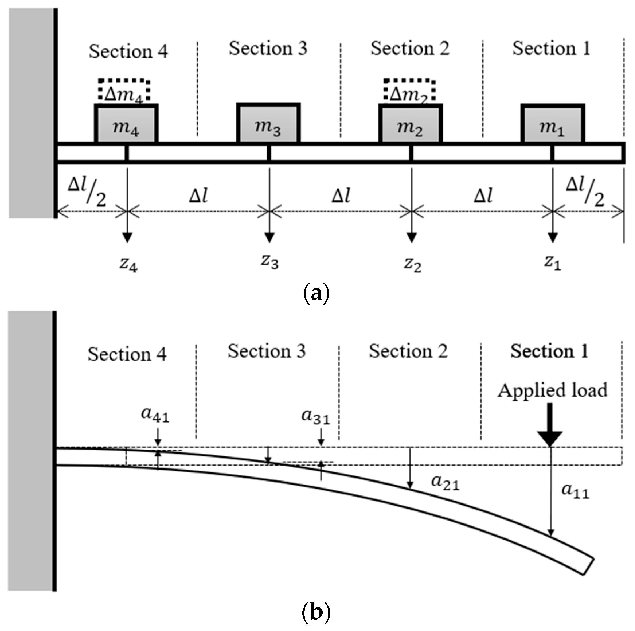
Rather than using Rayleigh’s method, an alternative discrete approach has been proposed [26] for analyzing the vibrations in a cantilever beam. This method divides the cantilever into multiple sections, treating each section as an individual mass interconnected with one another. The configuration of this discrete approach is illustrated in Figure 3a. In this approach, the cantilever is divided into n sections, and the mass is concentrated in the middle of each section. The total length of the cantilever is denoted as , and the total mass is denoted as . Without losing generality, all sections are assumed to be uniform and homogeneous. Thus, the lengths and masses of each individual section are and , respectively. The dynamic model for this discrete approach can be written as
where is the mass matrix, is the displacement vector of the cantilever at every point along the neutral axis, and is the stiffness matrix. When a proof mass is attached to the kth segment, its mass is incorporated into the corresponding mass term of that segment. By constructing the mass and stiffness matrices, the resonant frequencies can be determined. In the configuration illustrated in Figure 3b, the cantilever is divided into four parts, and the displacements of individual segments correspond to the movements in their centroids. To facilitate the analysis, the displacement is substituted with the harmonic functions
where represents the amplitude vector of individual segments, denotes the oscillating frequency, and represents the shifted phase of each segment. The next step is to substitute (6) into (5) and multiply the equation with an inverse matrix ; thus, (5) can be rewritten as
Then, replacing with , the following equation is obtained
Thus, the characteristic determinant of becomes
The elements of the matrix can be obtained by applying a single unit excitation at each position of mass concentrations along the cantilever. This process allows us to determine the resonant frequencies of the nth modes, which are represented by the corresponding eigenvalue . The mass matrix can be rewritten as
since there is no coupled mass among sections.
The cantilever beam can be partitioned into any desired number of segments, as long as all segments have identical lengths. This model can behave analogously to a continuous solution with the desired accuracy, especially when the number of segments is sufficiently large. The coefficients of the generalized flexibility matrix can be derived and are available in [44], which is as follows
where . To analyze the resonant frequencies of a cantilever beam with attached masses, the mass matrix needs to be adjusted. Instead of a simple diagonal matrix with identical coefficients, the modified mass matrix is a combination of two matrices: the original mass matrix and the matrix of attached mass . When proof masses are positioned at the corresponding sections, the mass matrix of the characteristic equation needs to be transformed into an equivalent mass matrix . In this study, the cantilever beam was assumed to be homogeneous. That is
where and is the mass of the divided cantilever beam attached at the kth section. Thus, the characteristic equation becomes
The deformation caused by external forces or loads applied to a particular section can be determined by calculating the derived model. In Figure 3b, a moment diagram for a four-segment cantilever beam is shown. When an applied load is imposed at Section 1 of the discretized model for the cantilever beam, the deformation of each individual section due to this load is denoted as , where i indicates the corresponding section and “1” indicates that the load is imposed at Section 1. For loads applied to other sections, the overall deformation resulting from all the loads can be obtained using the principle of superposition, summing up the individual deformations.
Additionally, all the eigenvalues of the matrices described in (12) can be calculated by solving the corresponding characteristic equation. This process allows for determining the frequencies associated with each individual mode. For this energy harvesting application, only the first two vibration modes were taken into consideration. Operating the energy harvesting components can result in an excited amplitude that is too small to collect a sufficient amount of energy. Additionally, the resonant frequencies in higher modes can be impractically high. The solution converges to a fixed value when the number of segments n is sufficiently large, ensuring convergence. For precise estimation of resonant frequencies, the number of segments for the piezo film must be determined. In this study, a total of 30 segments were used for this purpose.
3.2. Experimental Setup of the Vibration Test for a Single Piezoelectric Cantilever Beam
To validate the results of the theoretical model, two types of piezo films are utilized in this study. These components, i.e., DT1-028K and DT2-028K, are PVDF piezo sensor elements, featuring rectangular cantilevers with silver ink screen-printed electrodes. The minimum impedance is 1 MΩ, with a preferred impedance of ≥10 MΩ. Depending on the applied vibration amplitude and circuit impedance, the corresponding output voltage ranges from 10 mV to 100 V.
The two PVDF piezo films have different geometric shapes, with effective lengths of 40 mm for DT1-028K and 72 mm for DT2-028K. Figure 4 displays a piezo film DT2-028K used in this study, and the physical properties of both piezo films are listed in Table 1. As part of the experimental setup, attached proof masses of 0.3 g, 0.6 g, and 0.9 g were used. The experimental setup included an LDS mechanical shaker, a current amplifier, and a processing circuit with adequate impedance. The mechanical shaker was driven by a function generator that provides desired signals. Both the outputs of piezo films and the function generator were measured using a National Instrument PCI-6024E data acquisition board. The data acquisition system was constructed using MATLAB Simulink Real-Time toolbox, enabling acquired information to be sent to a host computer using a network connection. Figure 5 shows a schematic diagram of the experimental setup.
To acquire the frequency responses of the two piezo films, a swept sinusoidal waveform ranging from 5 to 500 Hz, with an amplitude of 0.25 mm, was generated using the signal generator over a 15 s period. This swept sinusoidal waveform was then applied to the current amplifier of the mechanical shaker to produce the desired mechanical vibrations. Subsequently, the data acquisition device measured the output voltage and current generated by the piezo films.
According to the theoretical model proposed in the previous section, the first mode resonant frequency of the DT1-028K is 53 Hz without any attached mass. For DT2-028K, the resonant frequencies of the first and the second vibration modes are 13 Hz and 81 Hz, respectively. Figure 6a displays the frequency response of DT1-028K, while Figure 6b illustrates the frequency response of DT2-028K. Both DT1-028K and DT2-028K exhibit significant output amplitude ratios at their first mode resonant frequencies. In these two figures, the frequencies indicated in the parentheses represent both the calculated resonant frequencies and the magnitudes corresponding to these frequencies. Additionally, the second vibration mode of DT2-028K can also generate a substantial amplitude ratio when operated in this mode. However, higher vibration modes of both piezo films are not considered in this study due to two reasons: (1) the output amplitude becomes too small because of the lowpass-filter phenomenon of mechanical systems and (2) there are very few high-frequency vibration sources in the natural environment.
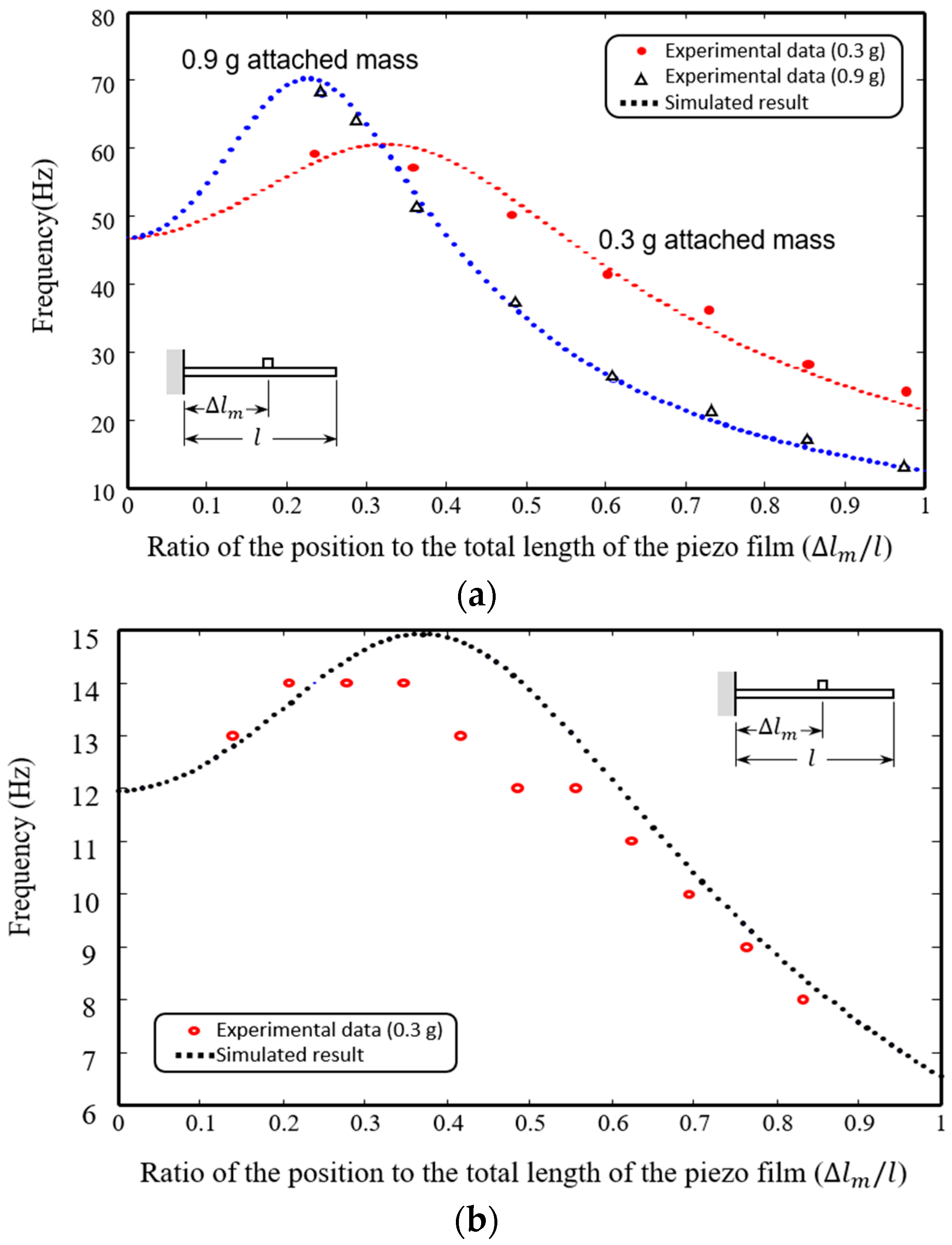
To fine-tune the resonant frequencies of the piezo films, proof masses with different masses were attached to the films individually at various locations. Figure 7a illustrates the variations in the first mode resonant frequencies for DT1-028K, with two different attached masses, i.e., 0.3 g and 0.9 g, placed at different distance from the fixed end. The frequency ranges of variation were from 22 to 60 Hz and from 13 to 71 Hz, respectively. Figure 7b shows a 0.3 g mass clipped to a DT2-028K piezo film, and the frequency band ranges from 6.5 Hz to 15 Hz. The 0.9 g mass was not used for testing due to its heavier weight, which resulted in more significant bending when placed at the end of the piezo film. The 0.9 g attached mass was not tested for DT2-028K due to significant geometric deformation of the cantilever caused by the relatively heavy mass. From the experimental results, it was determined that a heavier proof mass can significantly adjust the first mode resonant frequency with a minimal deviation in placement. Thus, the applicable frequency range for harvesting vibration energy lies between 6.5 and 71 Hz, which is achieved by combining these two types of piezo films.
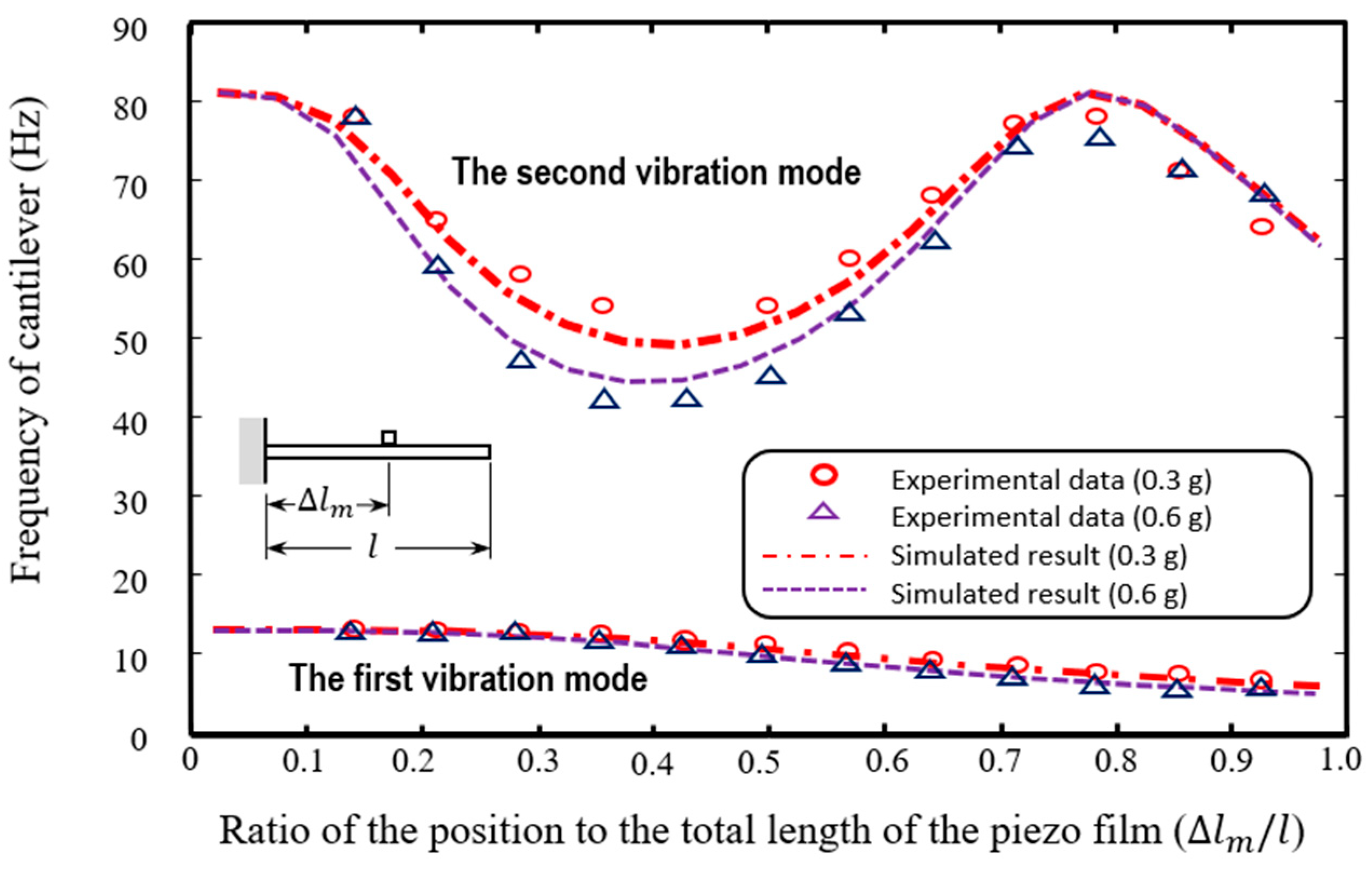
To further broaden the frequency range of an energy harvesting array, it is important to consider the second mode vibration. The second mode resonant frequencies of DT2-028K, without attached mass, was found to be 81 Hz. The variation in its second mode resonant frequency is presented in Figure 8, and it can be adjusted within the range of 50 Hz to 81 Hz by attaching a 0.3 g proof mass or within the range of 45 Hz to 81 Hz with a 0.6 g mass. In this study, the second vibration mode of DT1-028K was not taken into consideration due to its significantly higher second mode resonant frequency, which exceeds 300 Hz. Consequently, by combining the two piezo films DT1-028K and DT2-028K, the applicable frequency band for energy harvesting ranges from 6.5 Hz to 81 Hz, provided that proof masses ranging from 0.3 g to 0.9 g are carefully positioned at a designated location. The frequency band covers a broad range of vibration sources, ensuring that the energy-harvesting mechanism can adapt to diverse environments when utilizing these two types of piezo films in synthesis.
3.3. Collecting Energy Using Multiple Piezo Films and a Charging Circuit
A single piezo film can only generate a limited amount of harvestable energy, and its current might not be sufficient to drive the charging circuit properly to execute the correct charging procedures. To overcome this limitation, it is essential to group multiple piezo films together. By collecting energy from multiple energy-harvesting components, the harvested energy can be significantly increased, and the applicable frequency band can be expanded, leading to the maximization of the collected power.
For the 1.25 mm amplitude vibration, the DT2-028K piezo film generates a voltage of approximately ±10 V. However, this voltage can be too high to directly charge the battery unit without risking damage to the battery. A single piezo film often yields a high-voltage output with a tiny current. To ensure the energy-harvesting device functions effectively in different scenarios, an efficient charging mechanism and charging strategy must be developed. Directly connecting battery charging units to a piezoelectric component can lead to damage due to its high voltage output or suffer from insufficient current. Additionally, power leakage and the power required for operation can be issues due to the small amount of collectable power. To optimize the harvested energy, meticulous consideration was given to the selection of resistive loads. As a result, integrating low self-discharge components and low power consumption components becomes crucial for control units, charging circuits, and energy storage. Developing a smart charging strategy and advanced operating schemes for energy conversion is necessary to minimize operational power consumption. To address this, a voltage rectifier and an intermediate capacitor were connected in series to regulate the charging voltage source at a rated value. After the intermediate capacitor was charged to the rated voltage, it served as the power source for battery charging. This approach was used to mitigate potential risks associated with sudden high voltage, preventing any damage to the charging circuit and the battery unit.
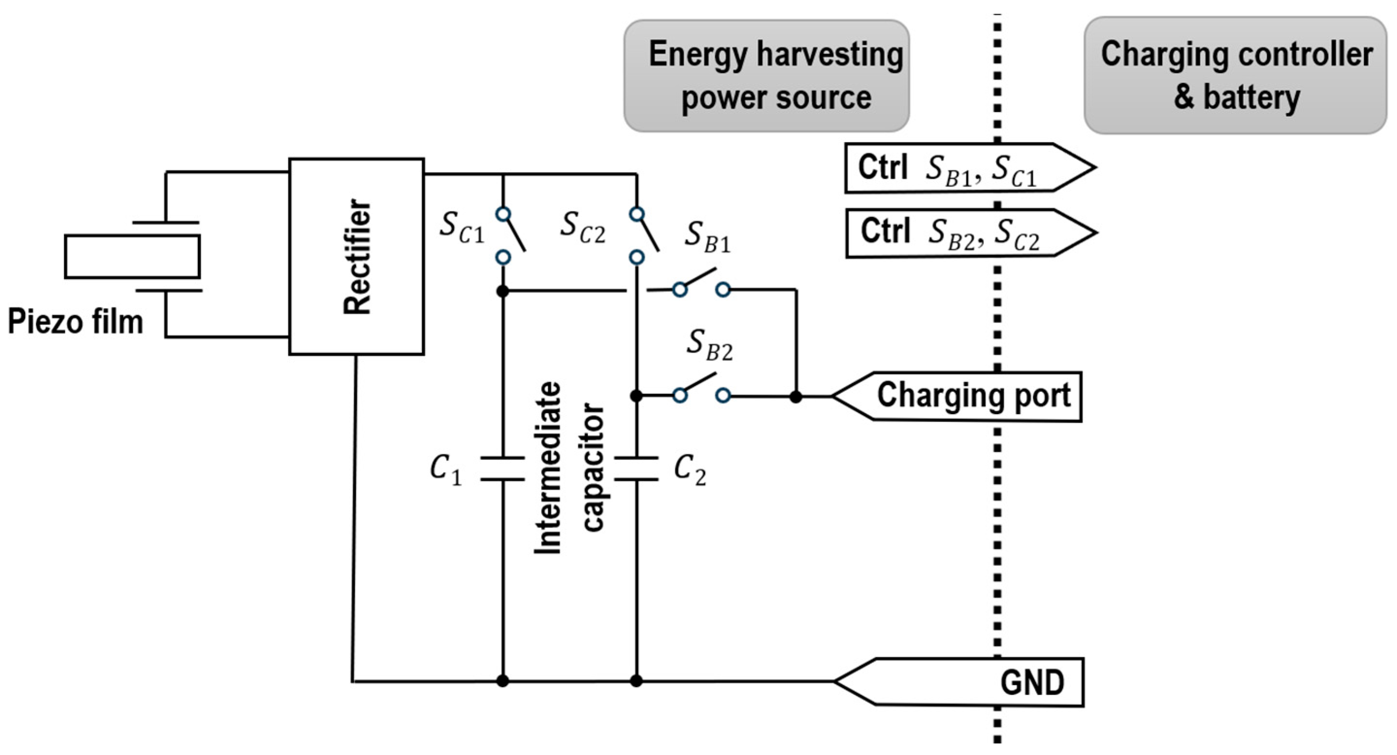
The proposed charging scheme is illustrated in Figure 9. Instead of directly charging the battery, low self-discharge capacitors were connected as an intermediate storage to a set of piezo films. In the preliminary design, piezo films with the same resonant frequencies were grouped together. The voltage outputs of all piezo films were parallelly connected after being rectified. To avoid damage caused by voltage spikes, the charging controller and the battery unit were not directly charged by the voltage outputs of the harvesting arrays. Instead, individual groups of energy-harvesting components were connected to two intermediate capacitors. Once the voltage of a capacitor charged from the energy-harvesting components exceeded a threshold, the corresponding capacitors were connected to the battery charging controller for the physical charging process. While the capacitor charged the battery, the piezo films were switched to another intermediate capacitor to store the harvested energy. This allowed one intermediate capacitor to charge the battery unit while the other continued to receive energy from the energy-harvesting array. The charging procedure can be controlled by turning the corresponding switches shown in Figure 9. In this proposed circuit design, SB1 and SB2 are responsible for managing the transfer of charge from the intermediate capacitor to the charging circuit, while SC1 and SC2 govern the charging process from the piezo film to the intermediate capacitor. To ensure the proper functioning of the charging controller and prevent any potential damage, the output voltage of the intermediate capacitor must be carefully regulated. It needs to be kept below a specific threshold () during operation to avoid damaging the charging controller with high input voltage. Additionally, the voltage level during the charge process needs to remain above another threshold () to prevent potential battery damage caused by deep discharge. Thus, considering these two factors, an operation strategy must be developed to toggle between individual arrays. Using this design, it becomes feasible to connect multiple piezo films or energy-harvesting arrays in parallel, enabling a larger charging capacity. This study used the specific values 6 V and 4 V. These voltage thresholds were carefully selected to ensure the safe and optimal operation of the charging mechanism.
Considering all these factors, the charging procedures were implemented using a microcontroller unit (MCU). However, during the harvesting process, the control unit needed to be in hibernate mode most of the time to save power. A management strategy must be developed to achieve two main objectives: (1) switch the charging schemes of the harvesting array based on environmental conditions and (2) learn the climate pattern for further evaluation.
4. Experimental Results
To investigate the variability in the harvestable amount of energy from energy-harvesting components or arrays, we used two vibration sources, including a mechanical shaker and a fabricated flow-induced vibration resonator. These sources were used to assess the amount of harvested energy from both single components and multiple films.
4.1. Harvestable Amount of Energy at Different Oscillating Frequencies—Single Piezo Film
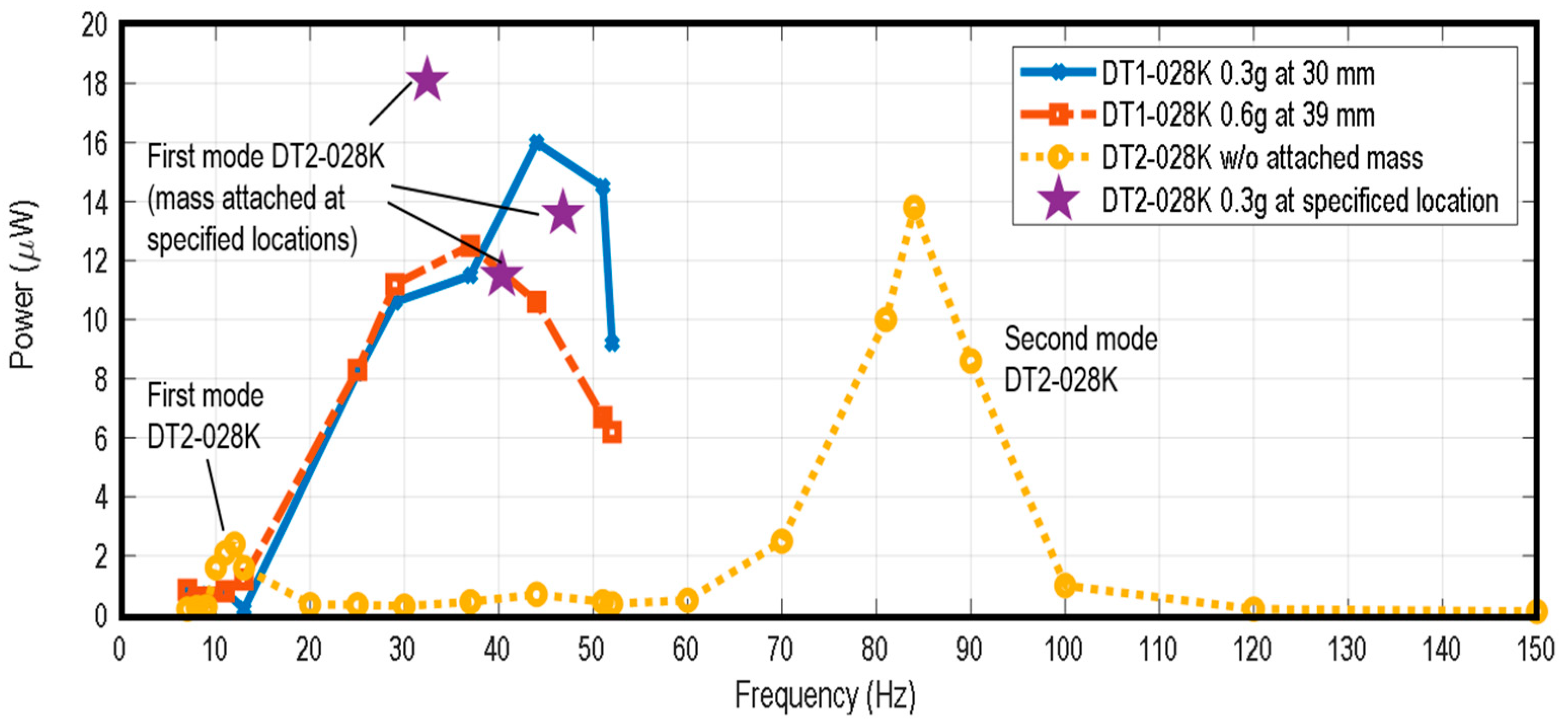
In this section, an experiment was used to determine the baseline of harvestable energy using a mechanical shaker as the vibration source. The oscillating amplitudes of the mechanical shaker were set to 1.25 mm. The resonant frequencies of individual energy harvesting components were set to match the vibration source, as per the proposed analysis. To evaluate the output power of the piezo films, individual components were tested at targeted excitation frequencies. Figure 10 demonstrates the output power of the two films with attached masses of different weights placed at specific positions. It is evident that the output power reaches its maximum when the components are operated at their corresponding resonant frequencies. However, the harvested energy quickly declines as the excitation frequency deviates from the mode frequencies. An important observation is that DT2-028K can generate significantly more power when operated in its second vibration mode. This phenomenon aligns with its frequency response shown in Figure 4b. The vibration amplitude in the second mode is almost the same as the amplitude in the first mode, while the frequency is approximately seven times higher. This indicates that the total traveled distance of the second mode operation is six times more than that in the first mode operation within the same duration. Consequently, the output power is also expected to increase proportionally.
Based on the tested results, the resonant frequency of DT1-028K with a 0.3 g mass attached at 30 mm is approximately 40 Hz, yielding a collected power of approximately 12 μW at this frequency. When a 0.6 g mass is attached at 39 mm, the energy collected by DT1-028K can increase to about 16 μW. As for DT2-028K, the energy collected without any attached mass exhibits two peaks. One peak is concentrated at around 12 Hz (the first mode), and the other peak is at 83 Hz (the second mode). The output power was also measured for the piezo film DT2-028K operating at three frequencies (45 Hz, 52 Hz, and 60 Hz). The corresponding output powers were found to be 0.3 μW, 0.3 μW, and 0.5 μW when the piezo film was operating without any attached mass. However, with a 0.3 g attached mass placed at the suitable locations (as shown in Figure 8), the maximum output powers at these frequencies increased significantly to 18.1 μW, 11.5 μW, and 13.6 μW, respectively. This improvement was achieved by operating the piezo film in its resonant mode with the mass attached at the correct locations. Notably, the amount of harvested energy in the second mode is significantly higher than in the first mode. However, the piezo film DT1-028K was not operated in its second vibration mode for two reasons in this study: (1) the required vibration frequency exceeded 150 Hz, which is much higher than most vibration sources in the natural environment; and (2) the amplitude decayed by more than 20 dB, making the harvesting process highly inefficient. Therefore, only the first vibration mode was tested in this study.
4.2. Energy Harvesting Array—Multiple Piezo Film
As observed in the previous section, it is evident that operating piezo films in a higher vibration mode can potentially yield a greater amount of harvestable energy. However, the increment is not always linearly proportional to the number of piezo films. The increase in harvestable energy depends on two key factors: (1) the number of connected piezo elements and (2) the phase difference among the piezo films. The maximal efficiency only occurs when there is no phase difference among individual piezo films.
During the test, an array consisting of four DT2-028K piezo films was connected in parallel. To observe the required charging time, a 470 μF capacitor was used as the intermediate capacitor. In this study, the solid-state battery charging circuit was an EnerChip CC-EVAL05 board, featuring two batteries: CBC3150 and CBC3112. The solid-state battery unit and the corresponding charging controller used in the charging controller need to maintain a voltage higher than 3.8 volts to prevent damage from deep discharge [20,45]. Thus, in each test, the capacitor was charged to 4.0 V before being switched to be charged by the energy harvesting array.
The energy harvesting array was tested at two frequencies: (1) 13 Hz without attached mass and (2) 52 Hz with a 0.3 g mass clipped at 22 mm. Table 2 lists the required charging time from 4 V to 6 V. Based on the experimental results, 400 s was required to charge the capacitor from 4 V to 6 V if only a single piezo film was operated at 13 Hz. If four piezo films were used, the charging duration dropped to 190 s. When operated in its second vibration mode (52 Hz with a 0.3 g mass clipped), the required charging time was 90 s if a single piezo component was used. The charging time was shortened to 22 s when four films harvested energy simultaneously.
When using a single piezo film, the required charging time at 52 Hz is about 25% of the duration at 13 Hz, which is close to a linear relationship. However, the array does not exhibit the same efficiency when operated in its first mode. Despite using four piezo films in the first mode, the phase differences among individual films can cause the charging time to vary by more than 50%. Conversely, while operating in its second mode, the variation in observed energy collected caused by phase differences among the films is much less significant.
Based on these results, we can conclude that charging is more efficient when the piezo films are operated in their second mode. Additionally, a higher operating frequency can help reduce the impact of phase deviations among the piezo components, leading to a more efficient charging sequence.
4.3. Harvesting Energy with a Flow-Induced Vibration Actuator—Single Piezo Film
To validate the feasibility of utilizing a flow-induced vibration actuator as an energy source, The experimental platform illustrated in Figure 1 was constructed. The cylinders were chosen to have a diameter of 10 mm. The downstream cylinder was placed at a distance of 42 mm from the upstream cylinder at . The experimental setup included a rectangular chamber with dimensions of 300 mm × 300 mm × 1000 mm (W × H × L), which was designed to direct the inlet airflow. The bluff body (upstream cylinder) was positioned 300 mm from the entrance of the airflow.
At one end of the cylinder positioned downstream, an energy harvesting unit consisting of a single piezo film weighing 0.24 g was fixed. To facilitate energy harvesting, one end of the cylinder was extended outside the chamber to securely attach the piezo film to it. To prevent any air leakage that might impact the flow-induced vibration, the extended cylinder was securely fixed with a lightly damped mechanism design. Given a constant airflow, it is assumed that an induced vortex can be created, resulting in the corresponding vibration. Based on these mechanical properties, the resonant frequency of this cylinder was approximately 35 rad/s, which corresponds to 5.69 Hz. The drag force caused by the connecting wire from the piezo film to the charging circuit was ignored. Considering the physical specifications of the hardware, the corresponding resonant frequency of the cylinder was determined at 5.69 Hz. If the inlet airflow was 3.4 m/s, the calculated Reynolds number was 4328, falling within the targeted range. For this Reynolds number, the Strouhal number was assumed to be 0.21, leading to a corresponding flow-induced vibration frequency of around 30 Hz. For the targeted operating mode, which is its second mode, attaching a 0.3 g mass to the piezo film at (~42 mm) of DT2-028K can yield a resonant frequency of around 12 Hz. Although these theoretical calculations provided nominal values, the physical outputs did not precisely match the calculated results. Under the given physical and environmental conditions, the energy output did not demonstrate a solid major sinusoidal periodical pattern. The effective amplitude of the vibration during the experiment was less than 1 mm.
At a flow speed of 6 m/s, the Reynolds number increased to 7638, and the resulting flow-induced vibration was estimated to be 20 Hz. Using a DT1-028K piezo film with a mass of 0.3 g positioned at 30 mm, a larger amplitude for energy harvesting was observed. Overall, the average harvested power for a single piezo film was only about 70% of the anticipated value based on the experimental results in the previous section. Several issues contributed to the inconsistent frequency observations: (1) possible turbulence and the inconsistent flow-induced vibration; (2) perturbation of the two-dimensional cycling movement; and (3) frequency deviation caused by the unbalanced mass of the attached energy-harvesting device.
4.4. Harvesting-Energy Array with a Flow-Induced Vibration Actuator
The energy-harvesting array used in this section consisted of four piezo films, and it was fixed at one end of the downstream cylinder, positioned outside the flow-induced chamber. The overall weight remained the same as the device with a single film in the previous section, and the targeted frequency remained at 20 Hz. However, due to the inconsistent phase shifts among individual piezo films, the frequency response of the measured outcome did not reveal a major peak that confirmed the frequency was close to 20 Hz. With the same setup of four DT1-028K films, the amount of harvestable energy was approximately 16 μW in this case. Although the amount of harvested energy increased, it was not proportional to the number of piezo films used.
The experimental results clearly show that an energy harvesting component can generate more energy when operating at its higher mode, as the total traveled distance is significantly greater compared with operating in its lower mode. The presence of a phase difference can lead to a degradation in the amount of harvestable energy while operating in the lower mode. Hence, optimizing the physical conditions of individual energy harvesting components, such as the piezo films in this study, can be a crucial factor that can lead to maximizing the total among harvested energy.
5. Conclusions
This study focused on investigating the potential of utilizing flow-induced vibration actuators as an energy source using piezoelectric energy harvesting. The study involved the analysis of piezo films configured as cantilever beams and their response to vortex shedding induced by fluid or wind stream. The goal was to maximize the collected energy from the vibrating structure. Using theoretical models and experimental validations, it was demonstrated that a flow-induced vibration actuator has the potential to harvest energy efficiently. The experiments revealed that higher operating frequencies in the second mode yielded better energy harvesting results compared with lower modes. However, phase differences among individual piezo films affected the accuracy of frequency measurements. The optimization of physical conditions for individual energy harvesting components, such as the piezo films, emerged as a key aspect for maximizing the overall harvested energy. By adjusting the resonant frequencies and implementing efficient charging mechanisms, the energy harvesting arrays can adapt to varying environmental conditions, ensuring effective energy collection. With the strategic adjustment of resonant frequencies using attached masses on individual piezo films, this study demonstrated that the harvestable energy of a single piezo film can be substantially increased from less than 1 μW to approximately 18 μW. With the carefully devised management strategy within the charging circuit, the energy harvesting mechanism can effectively charge the battery as well. The integration of the proposed charging mechanism with multiple piezo films, as demonstrated in the experimental results, holds the potential to significantly reduce the required charging time, thereby greatly enhancing the practicality and usability of this energy-harvesting approach.
Despite some challenges related to phase deviations and turbulence in the airflow, the results highlight the promising prospects of utilizing flow-induced vibration actuators as sustainable energy sources. To further enhance the efficiency of this energy harvesting approach, future research could focus on reducing phase variations and refining the design of the energy harvesting array. In conclusion, this study contributes valuable insights into harnessing flow-induced vibrations for practical energy harvesting applications. The findings lay the groundwork for future advancements in energy harvesting technologies, enabling environmentally friendly and renewable energy solutions.
Author Contributions
Conceptualization and methodology, Y.L. and M.H.C.; formal analysis, Y.L. and M.H.C.; investigation, M.H.C. and Y.L.; writing—original draft preparation, M.H.C.; writing—review and editing, H.E.C. and E.G.B. All authors have read and agreed to the published version of the manuscript.
Funding
This research received no external funding.
Data Availability Statement
The data presented in this study are available on request from the corresponding author.
Acknowledgments
The authors would like to acknowledge Larry Banta, Edward Sabolsky, Hailin Li, and Patrick Browning for offering feedback on this study.
Conflicts of Interest
The authors declare that they have no known competing financial interests or personal relationships that could have appeared to influence the work reported in this paper.
References
- Lin, B.; Giurgiutiu, V. Modeling and testing of PZT and PVDF piezoelectric wafer active sensors. Smart Mater. Struct. 2006, 15, 1085. [Google Scholar] [CrossRef]
- Bent, A.A.; Hagood, N.W.; Rodgers, J.P. Anisotropic actuation with piezoelectric fiber composites. J. Intell. Mater. Syst. Struct. 1995, 6, 338–349. [Google Scholar] [CrossRef]
- Vatansever, D.; Handimani, R.L.; Shah, T.; Siores, E. An investigation of energy harvesting from renewable sources with PVDF and PZT. Smart Mater. Struct. 2010, 20, 055019. [Google Scholar] [CrossRef]
- Wei, X.; Liu, X.; Zheng, C.; Zhao, H.; Zhong, Y.; Amarasinghe, Y.W.R.; Wang, P. A piezoelectric power generator based on axisymmetrically distributed PVDF array for two-dimension vibration energy harvesting and direction sensing. Sustain. Energy Technol. Assess. 2021, 44, 101001. [Google Scholar] [CrossRef]
- Lee, E.; Park, J.; Yim, M.; Kim, Y.; Yoon, G. Characteristics of piezoelectric ZnO/AlN-stacked flexible nanogenerators for energy harvesting applications. Appl. Phys. Lett. 2015, 160, 023901. [Google Scholar] [CrossRef]
- Wang, X.; Song, J.; Liu, J.; Wang, Z. Direct—Current nanogenerator driven by ultrasonic waves. Science 2007, 316, 102–105. [Google Scholar] [CrossRef] [PubMed]
- Lee, C.S.; Loo, J.; Han, S.; Koh, S.K. Multifunctional transducer using poly (vinylidene fluoride) active layer and highly conducting poly (3,4-ethylenedioxythiophene) electrode: Actuator and generator. Appl. Phys. Lett. 2004, 85, 1841–1843. [Google Scholar] [CrossRef]
- Kiriakidis, G.; Kortidis, I.; Cronin, S.; Morris, N.J.; Cairns, D.R.; Sierros, K.A. Tribological investigation of piezoelectric ZnO films for rolling contact based energy harvesting and sensing applications. Thin Solid Film. 2014, 555, 68–75. [Google Scholar] [CrossRef]
- Wischke, M.; Masur, M.; Goldschmidtboeing, F.; Woias, P. Electromagnetic vibration harvester with piezoelectrically tunable resonance frequency. J. Micromech. Microeng. 2010, 20, 035025. [Google Scholar] [CrossRef]
- Ibrahim, D.S.; Feng, Y.; Shen, X.; Sharif, U.; Umar, A.A. On geometrical configurations of vibration-driven piezoelectric energy harvesters for optimum energy transduction: A critical review. Mech. Adv. Mater. Struct. 2023, 30, 1340–1356. [Google Scholar] [CrossRef]
- Scheibner, D.; Mehner, J.; Reuter, D.; Gessner, T.; Dӧtzel, W. A spectral vibration detection system based on tunable micromechanical resonators. Sens. Actuators A Phys. 2005, 123, 63–72. [Google Scholar] [CrossRef]
- Ghasemi, S.; Afrang, S.; Rezazadeh, G.; Darbasi, S.; Sotoudeh, B. On the mechanical behavior of a wide tunable capacitive MEMS resonator for low frequency energy harvesting applications. Microsyst. Technol. 2020, 26, 2389–2398. [Google Scholar] [CrossRef]
- Chang, C.; Tran, V.H.; Wang, J.; Fuh, Y.-K.; Lin, L. Direct-write piezoelectric polymeric nanogenerator with high energy conversion efficiency. Nano Lett. 2010, 10, 726–731. [Google Scholar] [CrossRef] [PubMed]
- Zhang, Z.; He, H.; Fu, W.; Ji, D.; Ramakrishna, S. Electro-hydrodynamic direct-writing technology toward patterned ultra-thin fibers: Advances, materials and applications. Nano Today 2020, 35, 100942. [Google Scholar] [CrossRef]
- Shu, Y.C.; Lien, I.C. Analysis of power output for piezoelectric energy harvesting systems. Smart Mater. Struct. 2006, 15, 1499–1512. [Google Scholar] [CrossRef]
- Challa, V.R.; Prasad, M.G.; Shi, Y.; Fisher, F.T. A vibration energy harvesting device with bidirectional resonance frequency tenability. Smart Mater. Struct. 2008, 17, 015035. [Google Scholar] [CrossRef]
- Zhu, D.; Tudor, M.J.; Beeby, S.P. Strategies for increasing the operating frequency range of vibration energy harvesters: A review. Meas. Sci. Technol. 2010, 21, 022001. [Google Scholar] [CrossRef]
- Zhu, D.; Roberts, S.; Tudor, M.J.; Beeby, S.P. Design and experimental characterization of a tunable vibration-based electromagnetic micro-generator. Sens. Actuators A Phys. 2010, 158, 284–293. [Google Scholar] [CrossRef]
- Cheng, M.; Li, Y.J.; Sabolsky, E.M.; Chen, C.Y. Energy harvesting device with adjustable resonance frequency. ICIC Express Lett. 2011, 5, 3315–3320. [Google Scholar]
- Li, Y.; Cheng, M.H.; Bakhoum, E.G. Circuit development of piezoelectric energy harvesting device for recharging solid-state batteries. In Proceedings of the ASME International Mechanical Engineering Congress and Exposition, Houston, TX, USA, 9–15 November 2012. [Google Scholar] [CrossRef]
- Maamer, B.; Boughamoura, A.; El-Bab, A.M.F.; Francis, L.A.; Tounsi, F. A review on design improvements and techniques for mechanical energy harvesting using piezoelectric and electromagnetic schemes. Energy Convers. Manag. 2019, 199, 111973. [Google Scholar] [CrossRef]
- Song, H.C.; Kim, S.W.; Kim, H.S.; Lee, D.G.; Kang, C.Y.; Nahm, S. Piezoelectric energy harvesting design principles for materials and structures: Material figure-of-merit and self-resonance tuning. Adv. Mater. 2020, 32, 2002208. [Google Scholar] [CrossRef] [PubMed]
- Priya, S. Advances in energy harvesting using low profile piezoelectric transducers. J. Electroceram. 2007, 19, 167–184. [Google Scholar] [CrossRef]
- Khameneifar, F.; Arzanpour, S.; Moallem, M. A piezoelectric energy harvester for rotary motion applications: Design and experiments. IEEE ASME Trans. Mechatron. 2013, 18, 1527–1534. [Google Scholar] [CrossRef]
- Li, Y.J.; Cheng, M.H.; Bakhoum, E.G. Operation of energy harvesting devices in different vibration modes. In Proceedings of the 2013 IEEE EnergyTech, Cleveland, OH, USA, 21–23 May 2013. [Google Scholar] [CrossRef]
- Li, Y.J. Modeling and Tuning of Energy Harvesting Device Using Piezoelectric Cantilever Array. Ph.D. Dissertation, West Virginia University, Morgantown, WV, USA, 2013. Available online: https://researchrepository.wvu.edu/etd/6068/ (accessed on 10 August 2021).
- Li, M.; Luo, A.; Luo, W.; Wang, F. Recent progress on mechanical optimization of mems electret-based electrostatic vibration energy harvesters. J. Microelectromech. Syst. 2022, 31, 726–740. [Google Scholar] [CrossRef]
- Phillips, J.D. Energy harvesting in nanosystems: Powering the next generation of the internet of things. Front. Nanotechnol. 2021, 3, 633931. [Google Scholar] [CrossRef]
- Lobo, V.; Mainsah, N.; Banerjee, A.; Kimball, J.W. Design feasibility of a vortex induced vibration based hydro-kinetic energy harvesting system. In Proceedings of the 2011 IEEE Green Technology Conference, Baton Rouge, LA, USA, 14–15 April 2011. [Google Scholar] [CrossRef]
- Huera-Huarte, F.J.; Bearman, P.W. Vortex and wake-induced vibration of a tandem arrangement of two flexible circular cylinders with near wake interference. J. Fluids Struct. 2011, 27, 193–211. [Google Scholar] [CrossRef]
- Verma, M.; Mishra, A.; De, A. Flow characteristics of elastically mounted slit cylinder at sub-critical Reynolds number. Phys. Fluids 2021, 33, 12. [Google Scholar] [CrossRef]
- Giosan, I.; Eng, P. Vortex Shedding Induced Loads on Free Standing Structures. Available online: https://www.scribd.com/doc/164712587/Giosan-Vortex-Shedding-Induced-Loads-on-Free-Standing-Structures-pdf (accessed on 10 August 2023).
- Bryant, M.; Garcia, E. Modeling and testing of a novel aeroelastic flutter energy harvester. ASME J. Vib. Acoust. 2011, 133, 011010. [Google Scholar] [CrossRef]
- Pobering, S.; Schwesinger, N. A novel hydropower harvesting device. In Proceedings of the IEEE International Conference on MEMS, NANO, and Smart Systems, Banff, AB, Canada, 25–27 August 2004. [Google Scholar] [CrossRef]
- Li, S.; Yuan, J.; Lipson, H. Ambient wind energy harvesting using cross-flow fluttering. J. Appl. Phys. 2011, 109, 026104. [Google Scholar] [CrossRef]
- Yan, Z.; Shi, G.; Zhou, J.; Wang, L.; Zuo, L.; Tan, T. Wind piezoelectric energy harvesting enhanced by elastic-interfered wake-induced vibration. Energy Convers. Manag. 2021, 249, 114820. [Google Scholar] [CrossRef]
- Yu, K.R.; Étienne, S.; Scolan, Y.M.; Hay, A.; Fontaine, E.; Pelletier, D. Flow-induced vibrations of in-line cylinder arrangements at low Reynolds numbers. J. Fluids Struct. 2016, 60, 37–61. [Google Scholar] [CrossRef]
- Huang, X.; Zhang, C.; Dai, K. A multi-mode broadband vibration energy harvester composed of symmetrically distributed u-shaped cantilever beams. Micromachines 2021, 12, 203. [Google Scholar] [CrossRef] [PubMed]
- Srinil, N.; Zanganeh, H.; Day, A. Two-degree-of-freedom VIV of circular cylinder with variable natural frequency ratio: Experimental and numerical investigations. Ocean Eng. 2013, 73, 179–194. [Google Scholar] [CrossRef]
- Ottman, G.K.; Hofmann, H.F.; Bhatt, A.C.; Lesieutre, G.A. Adaptive piezoelectric energy harvesting circuit for wireless remote power supply. IEEE Trans. Power Electron. 2002, 17, 669–676. [Google Scholar] [CrossRef]
- Yang, W.; Stremler, M. Flow-induced vibration of a downstream cylinder in a tandem pair. In Proceedings of the 70th Annual Meeting of the APS Division of Fluid Dynamics, Denver, CO, USA, 19–27 November 2017. [Google Scholar] [CrossRef]
- Achenbach, E.; Heinecke, E. On vortex shedding from smooth and rough cylinders in the range of Reynolds numbers 6 × 10³ to 5 × 10⁶. J. Fluid Mech. 1981, 109, 239–251. [Google Scholar] [CrossRef]
- Achenbach, E. Total and local heat transfer from a smooth circular cylinder in cross-flow at high Reynolds number. Int. J. Heat Mass Transf. 1975, 18, 1387–1396. [Google Scholar] [CrossRef]
- Rao, S.S. Mechanical Vibrations, 6th ed.; Pearson: New York, NY, USA, 2018. [Google Scholar]
- Meier, R.; Kelly, N.; Almog, O.; Chiang, P. A piezoelectric energy-harvesting shoe system for podiatric sensing. In Proceedings of the 2014 36th Annual International Conference of the IEEE Engineering in Medicine and Biology Society, Chicago, IL, USA, 26–30 August 2014. [Google Scholar] [CrossRef]
Figure 1.
Configuration of the vortex-induced lightly damped cylinder.

Figure 2.
Simulation of the flow-induced vibration for a downstream cylinder in a tandem pair when the cylinder is placed at 2.1D and 3.9D.
Figure 2.
Simulation of the flow-induced vibration for a downstream cylinder in a tandem pair when the cylinder is placed at 2.1D and 3.9D.

Figure 3.
(a) Schematic showing a cantilever beam discretely divided into four sections, with two attached masses located in Sections 2 and 4, and (b) a moment diagram showing the discretized cantilever beam with four sections due to an applied load at Section 1 [26].
Figure 3.
(a) Schematic showing a cantilever beam discretely divided into four sections, with two attached masses located in Sections 2 and 4, and (b) a moment diagram showing the discretized cantilever beam with four sections due to an applied load at Section 1 [26].

Figure 4.
A DT2-028K piezo film with a 0.3 g attached pin.

Figure 5.
Experimental setup showing the vibration test of a single piezo film.

Figure 6.
Frequency responses of the two piezo films without any attached mass: (a) DT1-028K and (b) DT2-028K [26].
Figure 6.
Frequency responses of the two piezo films without any attached mass: (a) DT1-028K and (b) DT2-028K [26].

Figure 7.
Variation in the adjusted resonant frequencies from the modeled and experimental results for the first vibration mode of (a) DT1-028K and (b) DT2-028K [26].
Figure 7.
Variation in the adjusted resonant frequencies from the modeled and experimental results for the first vibration mode of (a) DT1-028K and (b) DT2-028K [26].

Figure 8.
Variation in the adjusted resonant frequencies from the modeled and experimental results for DT2-028K attached the attached masses of 0.3 g and 0.6 g [26].
Figure 8.
Variation in the adjusted resonant frequencies from the modeled and experimental results for DT2-028K attached the attached masses of 0.3 g and 0.6 g [26].

Figure 9.
Configuration of the charging scheme of the energy-harvesting power source.

Figure 10.
Output power of piezo films with different attached masses at different operating frequencies.
Figure 10.
Output power of piezo films with different attached masses at different operating frequencies.


Table 1.
Properties of the piezo films used in this study.
| DT1-028K | DT2-028K | |
|---|---|---|
| Length (mm) | 41 | 73 |
| Effective length (mm) | 40 | 72 |
| Width (mm) | 16 | 16 |
| Thickness (μm) | 230 | 230 |
| Density (kg/m3) | 1600 | 1450 |
| Mass (g) | 0.24 | 0.39 |
| Equivalent elasticity (GPa) | 8 | 4 |
| First mode frequency (Hz) | 53 | 13 |
| Second mode frequency (Hz) | 336 | 81 |
Table 2.
Required duration to charge a 470 μF from 4 V to 6 V.
| Required Charging Time (sec) | ||
|---|---|---|
| Operational Frequency | Single Piezo Film | Energy-Harvesting Array with Four Piezo Films |
| Operating at 13 Hz (without attached mass) | 400 | 190 |
| Operating at 52 Hz (with a 0.3 g mass clipped at 22 mm) | 90 | 22 |
Disclaimer/Publisher’s Note: The statements, opinions and data contained in all publications are solely those of the individual author(s) and contributor(s) and not of MDPI and/or the editor(s). MDPI and/or the editor(s) disclaim responsibility for any injury to people or property resulting from any ideas, methods, instructions or products referred to in the content. |
© 2023 by the authors. Licensee MDPI, Basel, Switzerland. This article is an open access article distributed under the terms and conditions of the Creative Commons Attribution (CC BY) license (https://creativecommons.org/licenses/by/4.0/).
Share and Cite
MDPI and ACS Style
Cheng, M.H.; Li, Y.; Camargo, H.E.; Bakhoum, E.G. Sustainable Energy Harvesting Mechanism with Flow-Induced Vibration. Machines 2023, 11, 902. https://doi.org/10.3390/machines11090902
AMA Style
Cheng MH, Li Y, Camargo HE, Bakhoum EG. Sustainable Energy Harvesting Mechanism with Flow-Induced Vibration. Machines. 2023; 11(9):902. https://doi.org/10.3390/machines11090902
Chicago/Turabian StyleCheng, Marvin H., Yuejuan Li, Hugo E. Camargo, and Ezzat G. Bakhoum. 2023. "Sustainable Energy Harvesting Mechanism with Flow-Induced Vibration" Machines 11, no. 9: 902. https://doi.org/10.3390/machines11090902
Note that from the first issue of 2016, this journal uses article numbers instead of page numbers. See further details here.