
Development of a Hand-Fan-Shaped Arm and a Model Predictive Controller for Leg Crossing, Walking, and One-Legged Balancing of a Wheeled-Bipedal Jumping Robot

Department of Human Intelligence and Robot Engineering, Sangmyung University, Cheonan-si 31066, Republic of Korea
*
Author to whom correspondence should be addressed.
Machines 2024, 12(5), 284; https://doi.org/10.3390/machines12050284
Submission received: 22 March 2024
/
Revised: 12 April 2024
/
Accepted: 15 April 2024
/
Published: 24 April 2024
(This article belongs to the Section Automation and Control Systems)
Abstract
:Bipedal walking robots are advancing research by performing challenging human-like movements in complex environments. Particularly, wheeled-bipedal robots are used in many indoor environments by overcoming the speed and maneuverability limitations of bipedal walking robots without wheels. However, when both wheels lose contact with the ground, maintaining lateral balance becomes challenging, and there is an increased risk of toppling over. Furthermore, utilizing robotic arms similar to human arms, in addition to wheel-based balance, could enable more precise and stable control. In this paper, we develop a wheeled-bipedal robot that is able to jump and drive while also being able to cross its legs and balance on one leg (the OLEBOT). The OLEBOT is designed with a hand-fan-shaped end-effector capable of generating compensatory torque. By tilting the hand-fan-shaped end-effector in the opposite direction, OLEBOT achieves pitch control and single-leg balance. In jumping scenario, it imitates the arm movements of a person performing stationary high jumps, while utilizing a cam-based leg joint system to boost jump height. In addition, this paper develops a control architecture based on model predictive control (MPC) to ensure stable posture in driving, jumping, and one-legged balancing scenarios for OLEBOT. Finally, the experimental results demonstrate that OLEBOT is capable of maintaining a stable posture using a wheeled-bipedal system and achieving balance in a one-legged stance.
1. Introduction
In the field of robotics, mobile robots are increasingly finding applications in various human services, including collaboration and task support. Bipedal walking robots such as Boston Dynamics’s Atlas are advancing in technology by performing challenging movements, including navigating rough terrains and executing parkour-like actions [1,2]. Specifically, wheeled-bipedal robots have overcome certain challenges encountered by bipedal walking robots by capitalizing on their inherently faster movement speeds and agility in directional changes [3,4,5]. Recent studies have concentrated on integrating bipedal walking robots with wheels, aiming to optimize the advantages of each to achieve rapid and adaptable motion in challenging terrains, thereby enhancing mobility and stability [6,7,8]. By combining technical elements, the wheeled-bipedal robot adeptly maneuvers challenging terrains and inclines using a single leg [9]. It overcomes obstacles through the flexion of leg joints and the rotation of wheels [10]. Moreover, the wheeled-bipedal robot has shown the ability to overcome obstacles larger than its wheel radius by performing controlled jumps to reach a specific height [11,12,13,14].
In the field of robotics research focused on overcoming challenging terrains and obstacles, the Inverted Pendulum Robot showcased its capability to ascend stairs with heights ranging from 120 mm to 130 mm. It achieved this task by utilizing a wheeled mechanism that incorporated belts, pulleys, and arms, completing each step in approximately 2.4 s [15]. Unlike jumping robots, the Inverted Pendulum Robot showcases its optimal performance on narrow staircases by surmounting them smoothly without requiring an acceleration phase over a fixed distance. Boston Dynamics’ Handle demonstrated its ability to transport a 45 kg box across uncomplicated terrains and overcome gaps as high as 1.2 m utilizing a hydraulic-driven system [16]. Moreover, Handle maintained a stable posture while navigating snow-covered slopes and swiftly traversing various staircases [17]. The Ascento robot successfully overcame a 10 cm step by accelerating and jumping over a distance of 90 cm [18,19]. Furthermore, the Ascento robot defines the states of fallen robots as “laying, sitting, planking, sideways”, and has developed a system that enables it to recover from these situations, achieving fall recovery in complex terrains.
To enhance jumping performance, Direct Drive Technology Ltd conducted research and introduced the Diablo robot, which incorporates a parallel four-bar linkage wheel-leg mechanism design to generate the energy required for jumping [20]. This mechanism adeptly adjusts the trajectory and height of the jump by modulating the energy release, which is contingent on alterations in the linked angles. EPFL’s Jumper aimed to enhance jumping performance through the mechanical design of a cam structure [21]. The cam structure stores spring energy by decreasing the angle of the torsion spring connected to the leg joints while the cam rotates. When the cam reaches its critical point, the leg link in contact with the cam reverts to its original position, immediately releasing the stored torsion spring energy. This cam structure design effectively maintains the torsion spring force by adhering to physical laws, instead of relying on motor power adjustments.
Despite these advancements, challenges remain. A significant limitation is the necessity for both wheels of a wheeled-bipedal robot to maintain contact with the ground during both movement and stationary poses. In terrains where the height difference between the two wheels in contact with the ground varies, or in narrow passages where both wheels cannot pass through, the wheels of the wheeled-bipedal robot do not maintain contact with the ground, and one of the wheels loses contact with the ground surface. Wheeled-bipedal robots primarily focus on balance control in the direction of travel, lacking control methods for lateral movement perpendicular to the direction of travel. When only one wheel is in contact with the ground, the uneven weight distribution increases the likelihood of wheeled-bipedal robots tipping or flipping in complex terrains. Consequently, these robots are currently limited to simple tasks, such as logistics processing, in indoor environments due to stability concerns. Moreover, in order to improve jumping performance, robots utilize compact motors and gear ratios to maintain their weight low. However, this approach necessitates extended waiting times for repeated jumps. Finally, wheeled-bipedal robots utilize various control modes depending on the situation (e.g., driving mode, jumping mode), requiring frequent adjustments in control systems, and joint mobility is constrained by the behavioral limitations defined in each control mode.
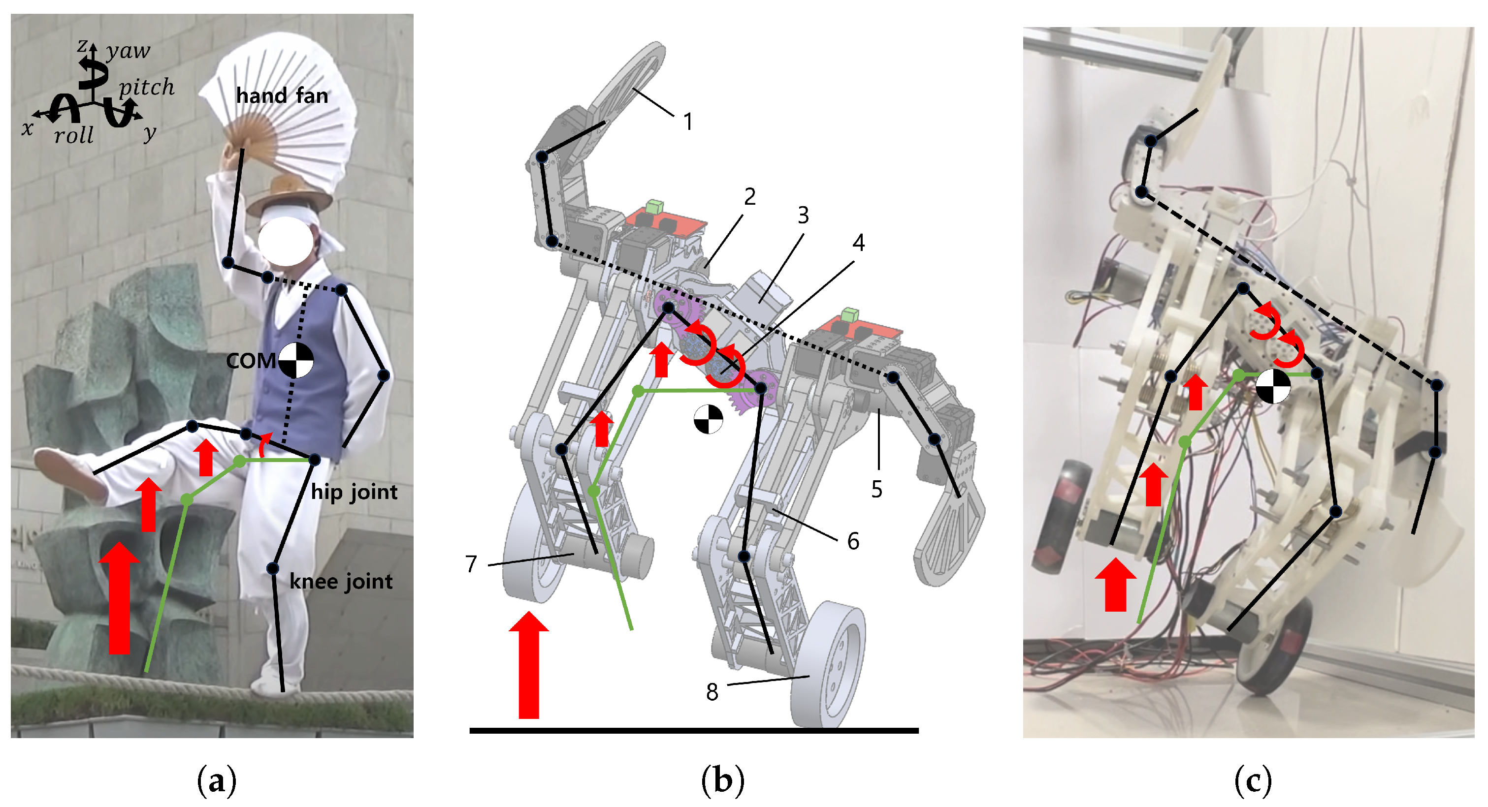
Therefore, this paper focuses on developing a wheeled-bipedal jumping robot equipped with a hand-fan-shaped end-effector capable of maintaining balance on a single leg, improving jumping performance over obstacles, and integrating control modes (OLEBOT). OLEBOT, drawing inspiration from traditional Korean tightrope walking as depicted in Figure 1a, is crafted with a hand-fan-shaped end-effector to produce torque in the opposite direction of leaning while in a single-leg posture [22]. A hand-fan-shaped robotic arm, designed with a large surface area to maximize the inverse momentum, increases the contact area with the air, and the related torque generated when the hand fan is rotated can be enhanced. The hand-fan-shaped end-effector allows OLEBOT to execute motions akin to ice skating using single-leg control, resulting in greater maneuverability compared to wheeled-bipedal robots. Using a hand-fan-shaped end-effector for balance control enables finer movements than wheeled-bipedal robots such as ’Handle’ and ’Ascento’ by utilizing the rotational inertia of a robotic arm. Additionally, OLEBOT can fine-tune its jump performance by arm movements, similar to a human-like standing high jump. Unlike the previous jump system that relied solely on leg joints, this new approach leverages both arm and leg joints for improved control and precision. In addition, this paper proposes a leg system composed of a hip joint with a cam structure and a torsion spring at the knee joint. The cam structure efficiently releases energy from the torsion spring during jumping, minimizing losses and enhancing energy efficiency. To ensure that the overall center of gravity remains perpendicular to the ground while adjusting the leg angle, the leg structure is designed as a four-bar linkage comprising a driving link and a passive link in contact with the cam. Furthermore, the paper presents an MPC-based control system, consolidating various control modes such as basic balancing, jumping and landing, single-leg driving, single-leg stopping, and single-leg maintenance into a unified framework. OLEBOT enhances system stability by mitigating the effects of uncertainties and external factors through model predictive control. The integrated system allows for flexible and simultaneous execution of all possible movements. The paper is structured as follows: In Section 2, we describe the operating principles and design of the hand-fan-shaped end-effector and cam-structured leg joint system. In Section 3, we detail the overall kinematics and dynamics modeling of OLEBOT, along with the description of the MPC control architecture based on the modeling. Section 4 presents simulation and real-world experimental results for MPC control based on the hand-fan-shaped end-effector and cam-structured leg joint. Finally, Section 5 and Section 6, we describe the performance differences between the conventional control methods and the proposed hand-fan-shaped end-effector, cam structure for leg joints, and integrated MPC control based on the experimental results. Furthermore, we discuss the areas for improvement and limitations of OLEBOT in these sections.
2. Design and Methods
OLEBOT is symmetrically designed with respect to the body, as depicted in Figure 1b,c. It consists of a waist motor, three-link robotic arm motors, and hip motors in pairs on both legs. The waist motor drives both legs in the same direction to raise one leg, while the three-link robotic arm motors are designed to compensate torque according to the roll and pitch angles. The hip motors turn the cam, generating torque exceeding the force exerted by the torsion springs, and store energy for jumping. An IMU sensor is placed at the center of the body to measure the robot’s posture information, while encoders on the wheel motors and hip motors measure rotation counts for precise position control. The robot’s torsion springs, up to four per leg, are designed to facilitate spring angle adjustments. The calf link, which connects the passive link and driving link in the leg, is designed as a truss structure. For more detailed information, please refer to Supplementary Materials Figure S1 and Table 1.
2.1. Hand-Fan-Shaped Arm
In this section, we describe the structure of a hand-fan-shaped robot arm for single-wheeled cross-driving and torque compensation based on the pitch angle of OLEBOT. As shown in Figure 2a, the hand-fan-shaped robot arm comprises three joints on both the left and right sides. The first joint is designed to rotate around the y-axis, ensuring that the hand fan’s plane remains perpendicular to the ground, as dictated by the pitch value from the IMU sensor. The second and third joints are configured to rotate around the x-axis, ensuring left-right balance based on the roll value from the IMU sensor. To prevent damage to physical components, the rotation ranges for the robot’s joints are configured as follows:
- The first joint has a rotation range from −45 degrees to 45 degrees.
- The second joint can rotate between 0 degrees and 180 degrees.
- The third joint’s rotation is limited to 0 degrees to 90 degrees, all based on the default posture.
OLEBOT is designed to control wheel speed and move both forward and backward based on the pitch angle. As shown in Figure 2b,c, this mechanism enables OLEBOT to achieve balance and come to a stop when the centers of the wheels and the center of mass (COM) of OLEBOT are aligned perpendicularly to the ground. Positioning the hand-fan-shaped robot arm opposite to OLEBOT’s movement direction, the center of mass (COM) is brought closer to being perpendicular to the ground. Consequently, the rotational speed of the wheels decreases, leading to a reduction in the overall movement speed. On the other hand, when the hand-fan-shaped robot arm remains stationary, the center of mass tilts more compared to when the arm is utilized. As a result, the rotation speed of the wheels increases, and the movement speed also increases. By using this mechanism, OLEBOT can be controlled more quickly and effectively by utilizing the hand-fan-shaped robotic arm rather than relying only wheel control. Typically, achieving higher movement speeds necessitates greater inclination. However, by minimizing the inclination while still maintaining a rapid movement speed, the hand-fan-shaped robotic arm facilitates stable posture maintenance and control. Furthermore, even though there is minimal wheel movement when OLEBOT is stationary, it mitigates fine movement by adjusting wheel output through the rotation of its hand-fan-shaped robotic arm.
As shown in Figure 2d, OLEBOT utilizes the hand-fan-shaped robotic arm to produce compensatory torque, maintaining single-wheeled balance and enabling single-wheeled cross-driving. As OLEBOT raises one leg by rotating both waist motors 60 degrees, a gap emerges between the wheel and the ground, resulting in a shift of the center of gravity toward that leg. To reduce the torque caused by the roll-directional center of gravity bias, both hand-fan-shaped robotic arms generate compensatory torque. The first joint of the hand-fan-shaped robotic arm is designed to maintain the fan’s plane parallel to the ground at all times when the arm is extended. This enables the second and third joints to consistently rotate along the horizontal x-axis according to the world coordinate system. It facilitates control of OLEBOT, which only tilts in the roll direction, even in a single-wheeled balance scenario. When the right leg of OLEBOT is lifted, torque is generated clockwise. In response to this, the second and third joints of both robot arms rotate counterclockwise. In this procedure, the right robotic arm is positioned directly above OLEBOT along the z-axis, ensuring that the COM remains vertically aligned with the ground where the wheels make contact. On the other hand, when OLEBOT’s left leg is raised, it generates a counterclockwise torque, causing both the second and third joints of the robot arms to rotate clockwise. At this time, the left robotic arm is aligned vertically above OLEBOT along the z-axis, ensuring that the COM remains parallel to the ground, where the wheels make contact. The operational principle of this hand-fan-shaped robotic arm ensures that the COM of OLEBOT, when one leg is raised, remains perpendicular to the ground, thereby maintaining a stable balance. Furthermore, the compensatory torque from offsets the torque generated by the roll direction tilt, converging it to zero.
2.2. Leg Joint System with a Cam Structure
OLEBOT is designed with a cam-structured leg joint system to release the force of the torsion spring without energy loss. The leg structure of OLEBOT is designed as a four-bar linkage comprising both actuated and passive links, which interact with the cam. This design ensures that the COM remains perpendicular to the ground while sitting down and standing up, allowing for angle control of the legs. As shown in Figure S2a, the torsion spring located at the robot’s knee alters the energy needed for jumping based on the knee joint angle. The actuated leg link comes into contact with the cam due to the force of the torsion spring, and the energy of the torsion spring is stored until the end of the actuated leg link, which is in contact with the cam, reaches the critical point as the cam rotates in one direction. As shown in Figure S2b, when the end of the actuated leg link passes through the cam’s critical point, the characteristic of the cam structure causes OLEBOT to instantaneously change from a sitting to its basic stance. During this process, as the passive and actuated leg links rotate, the torsion spring releases energy. This force enables OLEBOT to jump to a specific height.
3. System Modeling
3.1. Kinematics Modeling
In this section, we describe lateral modeling in the base posture and frontal modeling in the one-legged standing posture, as shown in Figure 3. As shown in Figure 3a, in the lateral model, the world coordinate system is denoted as {w}, where the x-axis is horizontal to the ground and the z-axis is vertical to the ground. The kinematics assume the center coordinates of the wheels as and consist of the segmented point masses of OLEBOT, denoted as (i = 1, 2, 3, 4, 5, 6). As shown in Figure 3b, in frontal modeling, the world coordinate system remains {w}, with the y-axis being horizontal to the ground, and the z-axis being vertical to the ground. The coordinates where the robot’s wheels touch the ground are set as , and the kinematics are derived based on the segmented point masses, denoted as mi (i = 7, 8, 9, 10, 11, 12, 13). Parameters such as mass, link length, and spring constants in the modeling are detailed in Supplementary Materials Table S1 [23].
In accordance with the established lateral kinematic model, the positional components for each mass point can be represented in matrix form, as shown in Equation (1) and Supplementary Materials Equations (S1)–(S6):
, the distance from the drive link joint to the body’s mass point, and , the distance from the passive link to the first joint of the hand-fan-shaped robot arm, are treated as virtual links. The angles formed with these virtual links are denoted as and . The variable x represents the distance OLEBOT has moved in the x-axis direction in the world coordinate system. The distance traveled by OLEBOT can be expressed as , where r is the distance the wheel has rotated. Additionally, assuming that the center of the wheels in the initial model touches the ground, z is set as 0.
As depicted in Figure 4b, in accordance with the established frontal kinematic model, the positional components for each mass point can be represented in matrix form, as shown in Equation (2) and Equations (S7)–(S13):
represents the angle between the body and the leg due to the rotation of the waist motor or the rotation angle between the body and the leg when lifting one leg to maintain one-legged balance. is the roll angle measured by the IMU sensor located at the center of the body, varying with changes in the body’s angle. The joint connecting and is fixed to the leg, maintaining a constant , and similarly, and also maintain . Additionally, assuming that the center of the wheels in the initial model touches the ground, z is set as 0.
By differentiating the positional components x, y, z of each mass point, the velocity components , , can be obtained. Expressing the velocity of the mass points as the sum of the squares of the velocity components yields Equation (3):
3.2. Dynamics Modeling
In this section, a dynamic model is designed for the basic posture, jumping and landing posture, and one-legged balance posture using Lagrangian equations. The design of the dynamic model involves assumptions to simplify and generalize the equations, as outlined in Assumptions 1–3.
Assumption 1.
Inertia moments and friction are neglected by assuming point masses.
Assumption 2.
In lateral modeling, excluding , point masses are symmetric components of OLEBOT, each with two.
Assumption 3.
Torsion springs are equipped with two in passive joints and two in the actuated joints. The angle of the unloaded torsion spring is set as .
The total kinetic energy k of the system is represented by Equations (4) and (5):
where represents lateral kinetic energy, denotes frontal energy, and .
The potential energy of the system includes the potential energy at each point mass and the torsion spring energy at the knee joint. The spring’s energy is designed as a quadratic function of displacement from the angle of the unloaded torsion spring. According to Assumption 3, the spring constant K applies to the displacements and . Therefore, the total potential energy p of the system is given by Equations (6)–(8).
where represents lateral potential energy, denotes lateral torsion spring energy, is frontal potential energy, and .
The Lagrangian L is obtained as , and the torque Q required for OLEBOT to achieve the basic posture, jumping and landing posture, and single-legged balance posture can be derived as shown in Equation (9). Furthermore, expressing it in general dynamic and state-space equations, we obtain Equations (10) and (11):
where , is the 8 × 8 mass matrix, is the 8 × 1 Coriolis vector, is the 8 × 1 gravity vector, , , A is the 8 × 8 system matrix, and B is the 8 × 1 input matrix.
3.3. OLEBOT Control System
Due to the significant shifts in the center of gravity resulting from changes in the values of each joint, OLEBOT requires precise control to maintain stability during one-legged balancing and post-jump landing poses. Furthermore, as shown in Figure 4a, the movement of each joint varies depending on the change in posture and state, necessitating the division of the controller into balancing control, jumping control, and one-legged balancing control for effective management.
3.3.1. Balancing Control
In this section, a model predictive controller (MPC) is designed to control one-legged balance, landing after a jump, and the base posture [24]. The MPC generates a control sequence of length by utilizing a predictive model of length , and adjusts the system’s performance through an optimization process [25]. The MPC is computed based on discrete time steps rather than continuous time. At the current time t, the state variables are measured, and the optimization problem J over the prediction horizon is solved to compute the control sequence within the control horizon [26]. Only the first term of the computed control sequence is applied to the system, and this process is repeated, shifting the prediction horizon by one step according to the moving time interval, forming a feedback control loop, as shown in Figure 4b.
As mentioned earlier, the MPC-based control system, operating in discrete-time steps, transforms the continuous-time Equation (11) into the discrete-time domain, as represented by Equation (12):
where k represents the k-th time within a discrete time step, is the discretized state matrix, and is the discretized input matrix.
In Equation (12), defining a new state-space model with the state variables as yields Equation (13):
where .
To design the prediction system, applying the previously mentioned prediction horizon and control horizon to the new state-space model results in Equation (14):
where , .
To obtain the optimal control inputs in the system through predictive modeling, the optimization function J is formulated in a quadratic equation form, as shown in Equation (15). The first term of Equation (15) represents the error between the reference state and the state at time step , minimizing the state error at each time step. This allows for precise control of the OLEBOT system. The second term, through the optimization of the changes in control inputs over , enables smooth and stable control. Additionally, constraints required for the optimization process to satisfy acceptable input variables and state conditions according to the actuated joints of OLEBOT are established, as depicted in Equation (16) [27]:
where Q and R are weight matrices and represents the reference state vector.
The first control input from an optimized control input sequence is fed into OLEBOT’s plant. When applied to each actuated joint in real-world conditions, this control input is subject to disturbances caused by external factors. Therefore, as illustrated in Figure S3, a Kalman filter is employed to reduce the error in IMU sensor and encoder readings, and a Savitzky–Golay filter (S-G filter) is utilized to stabilize the control input [28,29]. This process is repeated at every instance, forming a control loop system.
3.3.2. Jumping Control
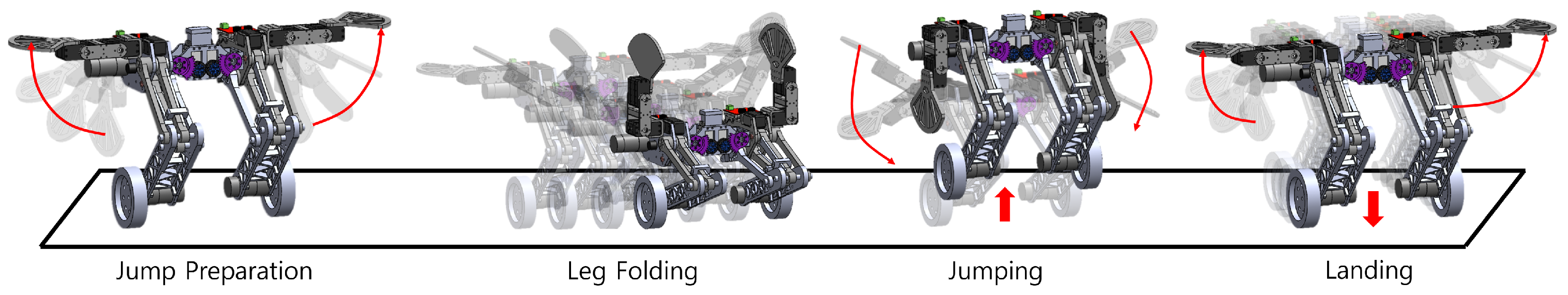
The jumping controller is activated upon receiving a jump command from the user. As shown in Figure 5, the jump motion is inspired by the human vertical jump motion and is controlled in four distinct phases:
- Jump Preparation: Upon the user’s jump command, the arms extended from the basic posture. During this phase, the balancing controller remains active, ensuring the first arm joint rotates according to the pitch inclination to maintain the hand fan horizontal to the ground.
- Leg Folding: The hip motors rotate until the driven leg links make contact with the cam’s critical point, thereby folding the legs. The rotation of the hip motors is closely monitored by encoders measuring each rotation angle to calculate error, which are then adjusted in real-time through MPC. Additionally, to prepare for the standing high jump, the hand-fan-shaped robotic arms are positioned vertically upwards towards the sky.
- Jumping: Upon confirmation of the synchronization between both hip motors, the driven leg links are adjusted to make contact with the cam’s initial position. At this point, the cam cannot rotate in the opposite direction, and the encoder rotation values are reset to zero. Furthermore, the hand-fan-shaped robotic arms rotate downwards at maximum speed to enhance the jump performance.
- Landing: Once the jump is detected through the encoder counts, the balancing controller is reactivated, and the hand-fan-shaped arms are extended to increase landing stability.
Figure 5.
OLEBOT’s posture transition and the movement of hand-fan-shaped robotic arms during the jumping process. The red arrow indicates the direction of movement of the hand fan.
Figure 5.
OLEBOT’s posture transition and the movement of hand-fan-shaped robotic arms during the jumping process. The red arrow indicates the direction of movement of the hand fan.

3.3.3. One-Legged Balancing Control
The one-legged balancing controller is activated upon user command. Prior to lifting one leg, the balancing controller is activated, and the hand-fan-shaped robotic arms extend laterally. The first arm joint rotates according to the pitch incline to maintain horizontal alignment between the ground and the hand-fan. To lift one leg, both waist motors rotate in the same direction by 60 degrees, and the hand-fan-shaped robotic arms instantaneously generate compensatory torque. This is depicted in Figure 2d. The error between the reference roll value and the current roll value is adjusted through the second and third torques of the left and right robotic arms, derived from the optimization of the MPC. Should the roll value exceed the threshold, the waist motors rotate back to their initial positions, preserving the posture prior to leg lifting.
4. Experiments and Results
In this paper, we validate the control performance through experiments with OLEBOT in both a 3D simulation environment and a real-world setting. As shown in Figure 6, the software development environment utilizes the Ubuntu 20.04 operating system and ROS2 Foxy, forming the node structure in the robot control system. Additionally, commands necessary for the ROS2 system are processed using Python 3.8 and C++ 23. Gazebo engine is employed for 3D physics simulation, and Arduino is used for communication with OLEBOT in the real environment, handling actuator and sensor signals. The designed STL files were converted into SDF format to be recognized within the Gazebo environment, and the resulting spawn into the Gazebo world is shown in Figure 7. To acquire sensor data within the simulation environment, Gazebo-provided IMU and encoder plugins were utilized. To visually represent actuation within the Gazebo environment, a /joint_control_plugin was developed, allowing for the input of control values into the actuated joints [30]. The sensor data and actuator input values are organized through a serial communication system involving two micro boards, as shown in Figure S4.
We experiment with two distinct control methods for pitch control. The first method approach only wheels for pitch control, while the second method involves the first joint of a hand-fan-shaped arm to compensate for torque. The experiments are initialized with a pitch of 0 radians, a wheel speed of 0 rad/s, and all link joint angles set to a default position. As shown in Figure 8a, the wheel speed converges to 0 within 0.25 s when controlling pitch without the use of the hand-fan-shaped end-effector. Conversely, when using the hand-fan-shaped end-effector for control, the wheel speed reaches zero within 0.21 s. This indicates that the control method, which combines both the wheels and the hand-fan-shaped end-effector, achieves converge 0.04 s faster than the method using only the wheels. Additionally, when using only wheels for control, the wheel’s maximum velocity was measured at 20.8891 rad/s. In contrast, when utilizing a hand-fan-shaped end-effector, the wheel’s maximum velocity was measured at 12.8101 rad/s. This shows that utilizing a hand-fan-shaped end-effector for control results in 40% reduction in the wheel motor’s maximum output compared to two-wheeled robot control approach. The decrease in wheel motor output, achieved by utilizing a hand-fan-shaped end-effector, ensures that the wheel output remains within the threshold required to maintain a stationary state. Consequently, this reduction leads to a decrease in fine movements, such as those observed in inverted pendulum motion.
Figure 8b,c show the outcomes of wheel torque and arm torque when maintaining a stationary posture under the influence of a 1 kg·f external force applied in the x-axis direction, comparing arm fixation control and control utilizing robotic arms. Before applying an external force, the OLEBOT remains a stationary state using a balancing controller. In the external force stability experiments, OLEBOT maintained a stationary state without utilizing the hand-fan-shaped end-effector, using a maximum wheel torque of 4.5 N·m. In contrast, OLEBOT utilizing the hand-fan-shaped end-effector used a maximum wheel torque of 2.1 N·m. This shows the capability of the compensation torque and the center of gravity shifting mechanism of the hand-fan-shaped end-effector to reduce the wheel torque by approximately 2.4 N·m. Moreover, the control method utilizing the hand-fan-shaped end-effector stopped after moving 15 cm upon the application of external force and reached a stable threshold within 0.4 s. On the other hand, the control method with the hand-fan-shaped end-effector fixed resulted in the system stopping after moving 24 cm and reaching a stable threshold within 0.6 s. These results show that the control method using a hand-fan-shaped end-effector is faster and more efficient than the conventional two-wheeled robot control method.
In this paper, we conducted experiments on a jumping scenario, where the second joint of a hand-fan-shaped robotic arm was fixed, and jump control was performed with the arms extended. Furthermore, we simultaneously conducted experiments with the application of the proposed jump control mechanism in this paper. The initial conditions for this experiment were set with a hip joint angle of 0 radians and the center height of the wheel at 0.05 m.
As shown in Figure 9b, the hip joint rotated from 0.6 to 1.05 radians during the leg-folding process, with an average measurement error of 0.02 radians. Additionally, when the driven leg link passed the critical point of the cam and initialized, we observed that the error momentarily increased but quickly converged to the reference value within 0.1 s.
When the second joint of the hand fan-shped robotic arm was fixed, enabling the arm to extend for jump control, the maximum jump height measured was 0.1 m. As shown in Figure 9a, the wheel velocity reached convergence within 0.8 s after the jump, indicating stable control performance. Furthermore, as shown in Figure 9c, the first joint angle of the hand-fan-shaped robot arm converged within 2 s after the jump. These results demonstrate the significant effect of the compensatory torque and center of mass shifting mechanism of the hand-fan-shaped robot arm in achieving stable posture control of OLEBOT after landing.
In the experiment applying the jump control mechanism, a maximum jump height of 0.14 m was measured. This result demonstrated that OLEBOT, through a human-like jumping posture, achieved a jump height 0.04 m higher than a fixed-arm jump. However, as shown in Figure 10a, the wheel velocity converged within 0.7 s after the jump, showing little difference compared to the results with the hand-fan-shaped robot arm fixed.
As shown in Figure 10b, in the jump preparation section, it can be observed that the second joint angle of the robot arm rotated by 1.57 radians from the initial posture to extended the arm. Furthermore, in the leg folding section, the robot arm rotated by 3.14 radians to position the hand-fan-shaped robot arm upward towards the sky. In the jumping section, the second joint of the hand-fan-shaped robot arm momentarily rotated to the initial angle of 0 radians and generated a maximum torque of 0.7, as shown in Figure 10c. This torque generated by the robot arm indicates the application of compensatory force that enables a higher jumping capability than the original jump force. Lastly, in the landing section, it was confirmed that by rotating the second joint of the hand-fan-shaped robot arm by 1.57 radians when the wheels made contact with the ground, extending the arms apart in both directions, stable landing and posture maintenance were achieved.
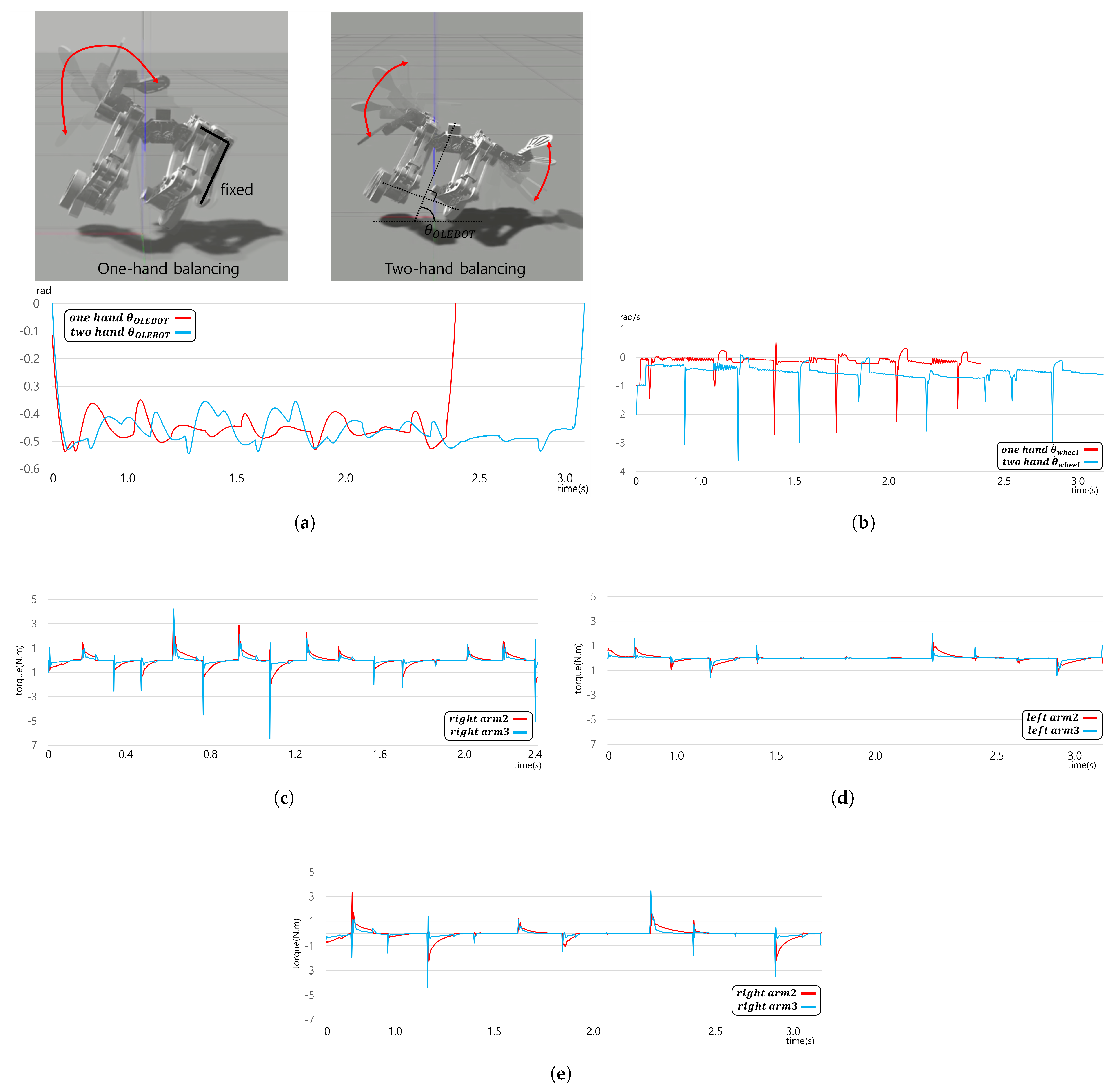
In this study, we compare and analyze the effects of using a hand-fan-shaped robotic arm control method for performing one-legged balancing in OLEBOT of a stationary state. The experiment establishes the initial conditions by setting all joint angles of the robot arm to default posture and controlling the waist angle to 60 degrees to raise the right leg of the OLEBOT. In this experiment, we compare the effects of control using only one arm and control using both arms. As shown in Figure 11a, in the one-legged balancing situation, OLEBOT maintained an average angle of −0.45 radians. Control using only one arm was able to maintain one-legged balancing for 2.4 s, while control using both arms was able to maintain it for 3 s, indicating that using both arms allowed for 0.6 s longer one-legged balance. As shown in Figure 11b, the wheel velocity in the one-legged control state was controlled based on the pitch direction’s inclination change. In particular, a phenomenon of momentary wheel velocity of up to 3.5 m/s occurring with a period of approximately 0.4 s was observed. The dynamic movement of the wheel showed similarities to the momentary compensatory torque generated by the periodic motion of the robot arm, indicating that the robot arm’s movement plays a crucial role in one-legged pitch control situations.
Furthermore, in this experiment, we compare the joint torques of control using only the right hand-fan-shaped robotic arm and control using both hand-fan-shaped robotic arms. As shown in Figure 11c, when using only the right hand-fan-shaped robotic arm, a maximum force of 7 N·m was used to generate compensatory torque. On the other hand, as shown in Figure 11d,e, when using both hand-fan-shaped robotic arms, the left robotic arm exhibited a maximum force of 2.5 N·m, and the right robotic arm exhibited a maximum force of 4 N·m, resulting in more torque generation by the right robotic arm. This result indicates that the movement of the robotic arm on the side where the lifted leg is located has a significant influence on the control performance in one-legged control, and the robotic arm or leg in contact with the ground assists in aligning the weight center of OLEBOT with the vertical axis of the ground through fine movements. Furthermore, control using both hand-fan-shaped robotic arms generated small joint torques for each arm compared to control using only one arm. This result minimizes the movement of the robotic arm by reducing the inertia caused by arm rotation, enabling more stable control and improving OLEBOT’s ability to maintain balance.
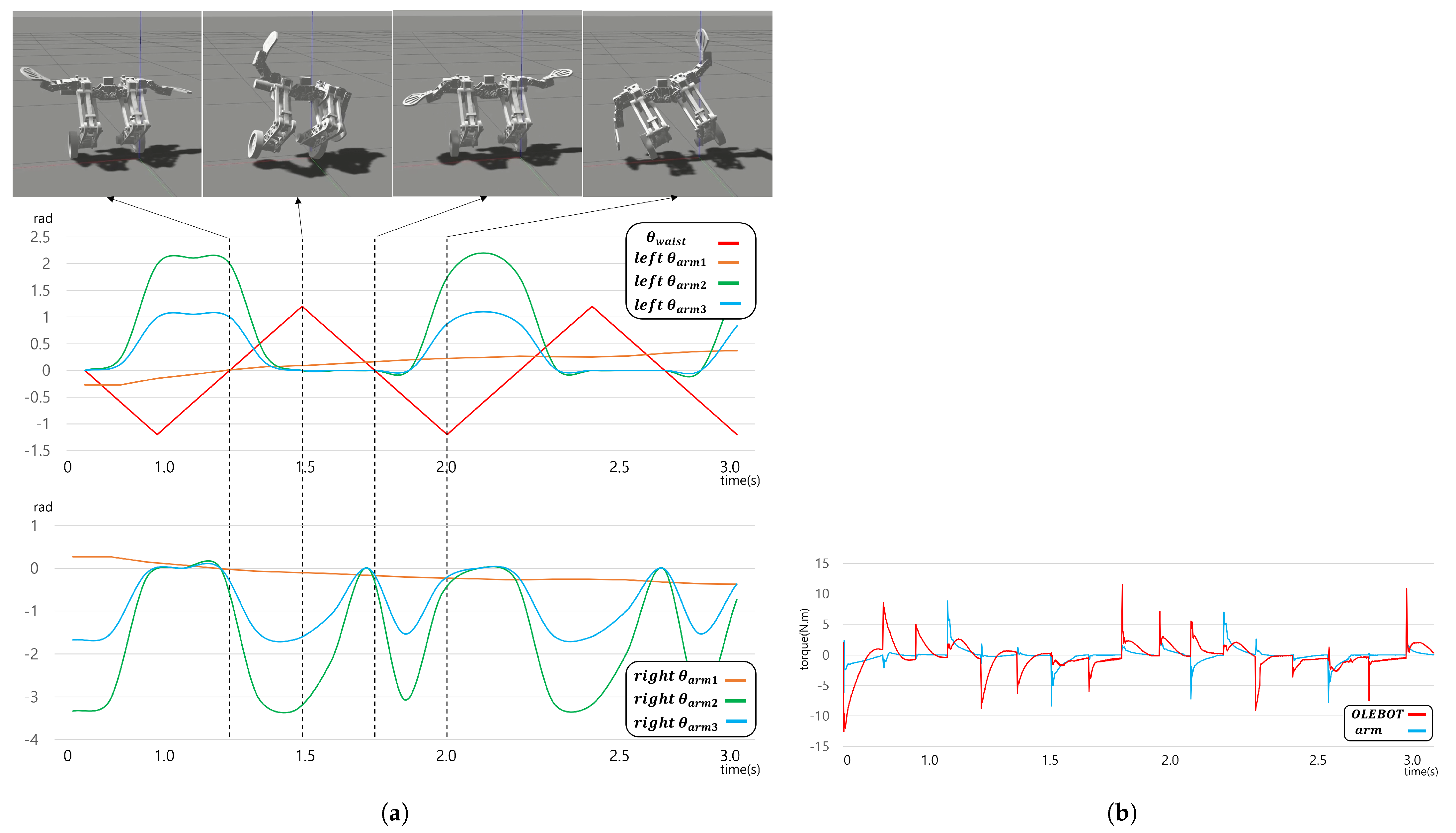
The purpose of this experiment is to measure the operation of the hand-fan-shaped robot arm and the compensatory torque generated during the maintenance of balance while performing single-leg cross motion in place. During the experiment, OLEBOT alternates legs at intervals of 0.5 s, rotating the waist angle by 60 degrees during leg replacement. As shown in Figure 12a, the hand-fan-shaped robot arm moved the arm similar to a tightrope walker. The robot arm on the side where the leg is lifted exhibited a large range of motion towards the upward direction, while the robot arm on the side in contact with the opposite ground performed fine adjustments within a range similar to the initial posture. This movement pattern evokes the motion of ice skating and demonstrates that OLEBOT can maintain balance and move. Additionally, as shown in Figure 12b, it is observed that the torque generated by the inclination to the left and right is compensated for by the robot arm, with a root mean square error (RMSE) measured at 2.16. This indicates that the error falls within an acceptable range for maintaining balance while alternating legs at 0.5-s intervals. Despite the differences in the error range, the results of this experiment demonstrate the possibility of maintaining balance in place through continuous leg replacement.
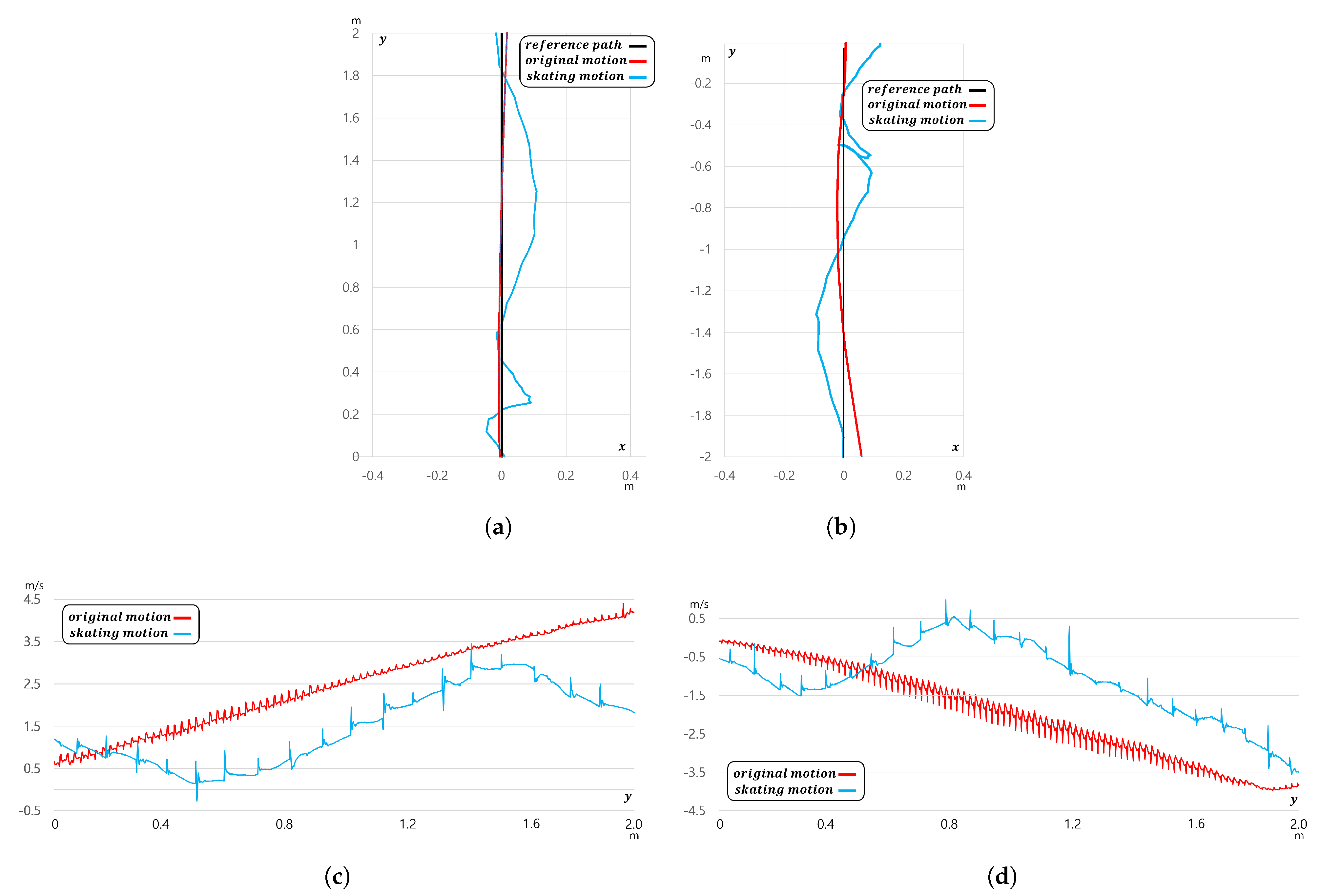
In this experiment, we compared and analyzed the performance of OLEBOT’s driving using the conventional two-wheel balancing method and the single-leg cross driving method using skating motion. The experiments were conducted in the Gazebo world coordinate system, with the starting point set at . The experiments involved OLEBOT moving forward by 2 m in the y-axis direction and moving backward by −2 m. In these experiments, the desired pitch angle of OLEBOT was set to 0.2 radians for forward motion and −0.3 radians for backward motion.
The experimental results showed that when using the conventional posture, it took 3.651 s to reach the target point during forward motion, while it took 5.847 s when using the skating motion. Therefore, the conventional posture reached the target point approximately 2.196 s faster than the skating motion. Similar results were observed in the backward experiments, with the conventional posture taking 3.627 s and the skating motion taking 5.856 s to reach the target point. This indicates that the conventional posture reached the target point approximately 2.229 s faster than the skating motion during backward motion. The speed difference between forward and backward motion was not significant, indicating that the weight distribution of OLEBOT’s front and rear centers of gravity was balanced. However, as shown in Figure 13a,b, the analysis of OLEBOT’s movement path revealed significant differences between the movement paths when using the conventional posture and the skating motion. When driving with the conventional posture, OLEBOT accurately followed the reference path by controlling the speeds of the two wheels in contact with the ground according to the yaw value. On the other hand, when driving with the skating motion, it was difficult to control the lateral movement with only one wheel in contact with the ground, resulting in the inability to adjust the direction. This led to errors and increased the total travel distance.
In Figure 13c,d, the speed analysis results also showed significant differences between the conventional posture and the skating motion. When driving with the conventional posture, both wheels were in contact with the ground, resulting in minimal disturbances and allowing OLEBOT to move quickly at a maximum speed of 4.2 m/s, following the desired pitch angle. In contrast, when driving with the skating motion, OLEBOT experiences significant vibrations and a high level of disturbances, causing its maximum speed to decrease to 3.5 m/s. This represents a reduction of approximately 16.7% compared to when it is driven in a normal posture. Additionally, reverse rotation of wheel or stopping was observed to maintain pitch balance. These results indicate that driving with the conventional posture allows for faster movement compared to skating motion driving.
5. Discussion
In this paper, we presented the results of using a hand-fan-shaped end-effector for pitch and one-legged balancing control, a cam-structure-based leg joint system for jumping, and MPC for OLEBOT. The one-legged balancing control method, where only single wheel touches the ground, exposed its limitations in lateral control. Particularly, in the moment when both legs made contact with the ground during the single-leg cross-driving process, continuous directional correction using both wheels was essential for maintaining the desired direction of OLEBOT. Additionally, we observed instances where OLEBOT made contact with the ground using the edges of the wheels instead of the wheel surface during one-legged balancing control, which added significant difficulty to the directional correction process. It is expected that designing the wheel with a surface structure instead of edges could alleviate these issues and enable more stable control.
In one-legged balancing control, multiple control variables are introduced, including robot arm joints. These variables can lead to computational speed degradation during the MPC optimization process. Considering that the average reaction time for an adult is 0.02 s and accounting for the 6.8-fold scale difference between OLEBOT and human proportions, the ideal data transmission time for OLEBOT would be within 0.136 s. However, experimental results indicate that the average time for data to be input into OLEBOT’s actuators is as long as 0.253 s. This suggests that delays in computational speed may impact OLEBOT’s real-time responsiveness. Therefore, simplifying OLEBOT’s modeling and controller can enhance MPC computational speed and allow for faster data transmission, ultimately improving OLEBOT’s driving performance and stability.
The results of the gazebo simulation and actual OLEBOT performance for jumping showed some discrepancies. OLEBOT jumped 0.14 m in the simulation, while it jumped 0.1 m in the real environment. The simulation environment was set to be similar to the actual environment in terms of OLEBOT’s mass, friction coefficient, and torsion spring constant. However, factors that additionally affect the real environment, such as the weight of micro boards and wires, were not considered. The most significant cause of the difference in jumping performance between simulation and the real environment was the variation in torsion spring elasticity. Torsion springs find it challenging to recover elasticity when exposed to a load for an extended period. OLEBOT, even in situations where the torsion spring is not driven, is exposed to a significant force on the knee joint, leading to spring aging in many experimental processes. Therefore, periodic replacement of the torsion spring is necessary to maintain jumping performance, and modular design for easy replacement of the torsion spring is required in OLEBOT’s design.
The success rate for maintaining a stable posture after jumping was 80% in the simulation environment and 70% in the real environment. Unstable landings varied significantly depending on changes in pitch angle in the posture just before jumping. In the stable pitch angle range just before jumping, the pitch angle is between −0.21 radians and 0.11 radians. If leaping occurs outside this angle range, OLEBOT cannot maintain its posture stably upon landing, as the center of gravity does not remain perpendicular to the ground. If the pitch angle and ref angle differ by more than 0.14 radians at the landing point, OLEBOT could not maintain a stable posture and balance after jumping. Therefore, to increase the success rate of maintaining a stable posture after jumping, it is necessary to limit the range of the error between the ref pitch angle and pitch in the posture just before jumping and improve the algorithm for OLEBOT to jump when it is within a stable error range.
6. Conclusions
In this paper, we introduced OLEBOT, equipped with a hand-fan-shaped end-effector capable of one-legged balance, jumping, and balancing. The design of the hand-fan-shaped end-effector allows for one-legged balance and enhances balancing control performance through robotic arm rotation. Additionally, the leg design with a cam structure, utilizing a four-bar linkage, maintains the center of gravity vertically with respect to changes in the leg joint angles of OLEBOT. It minimizes jumping energy loss by releasing energy from the spring in a trigger-like fashion, without instantly removing the force from the motor. OLEBOT maintained a stable posture through the optimization of integrated MPC in jumping, balancing, and one-legged balance scenarios. In the balancing experiment, the use of hand-fan-shaped robotic arms improved the fine movement control capability of the robot when in a stationary state. Furthermore, it was confirmed that the robot could maintain balance for a duration of 3 s while remaining in a one-legged stance. In the jumping experiment, the utilization of the hand-fan-shaped robotic arm mechanism demonstrated a 40% improvement in jump height compared to the conventional jumping method. On the other hand, in the single-leg cross-driving experiment, although the movement speed was slower by 2.229 s compared to driving in a conventional posture, it successfully demonstrated the feasibility of single-leg cross-driving, thereby proving its usefulness in robot operations in irregular terrains or confined spaces. Future work includes simplifying the modeling to improve MPC computational speed and utilizing LiDAR and camera sensors to predict OLEBOT’s environment, aiming to enhance control performance.
Supplementary Materials
The following supporting information can be downloaded at: https://www.mdpi.com/article/10.3390/machines12050284/s1, Figure S1: Comprehensive sketch and detailed images of leg joints of OLEBOT; Figure S2: Leg system consisting of a cam-structured hip joint and a knee joint with a torsion spring; Figure S3: Filtering results used in the model prediction controller; Figure S4: Sensor and actuator micro board communication system; Table S1: The parameters for OLEBOT; Video S1: Experimental results in simulated and real-world environments.
Author Contributions
Conceptualization, K.Y.; methodology, S.K.; software, S.K.; validation, S.K. and K.Y.; formal analysis, S.K. and K.Y.; investigation, S.K.; resources, K.Y.; data curation, S.K.; writing—original draft preparation, S.K.; writing—review and editing, K.Y.; visualization, S.K.; supervision, K.Y.; project administration, K.Y.; funding acquisition, K.Y. All authors have read and agreed to the published version of the manuscript.
Funding
This research was funded by a 2023 research Grant from Sangmyung University (2023-A000-0227).
Data Availability Statement
Datasets available on request from the authors.
Acknowledgments
Authors thank the Birobot & Autonomous Control Lab for helping design and realization of the robot.
Conflicts of Interest
The authors declare no conflicts of interest.
References
- Feng, S.; Whitman, E.; Xinjilefu, X.; Atkeson, C.G. Optimization based full body control for the atlas robot. In Proceedings of the IEEE-RAS International Conference on Humanoid Robots, Madrid, Spain, 18–20 November 2014; pp. 120–127. [Google Scholar]
- Atkeson, C.G.; Benzun, P.B.; Banerjee, N.; Berenson, D.; Bove, C.P.; Cui, X.; DeDonato, M.; Du, R.; Feng, S.; Franklin, P.; et al. Achieving Reliable Humanoid Robot Operations in the DARPA Robotics Challenge: Team WPI-CMU’s Approach. In The DARPA Robotics Challenge Finals: Humanoid Robots to the Rescue; Springer International Publishing: Cham, Switzerland, 2018; pp. 271–307. [Google Scholar]
- Zhang, Y.; Zhang, L.; Wang, W.; Li, Y.; Zhang, Q. Design and implementation of a two-wheel and hopping robot with a linkage mechanism. IEEE Access 2018, 6, 42422–42430. [Google Scholar] [CrossRef]
- Xin, Y.; Chai, H.; Li, Y.; Rong, X.; Li, B.; Li, Y. Speed and acceleration control for a two wheel-leg robot based on distributed dynamic model and whole-body control. IEEE Access 2019, 7, 180630–180639. [Google Scholar] [CrossRef]
- Vollenweider, E.; Bjelonic, M.; Klemm, V.; Rudin, N.; Lee, J.; Hutter, M. Advanced skills through multiple adversarial motion priors in reinforcement learning. In Proceedings of the IEEE International Conference on Robotics and Automation (ICRA), London, UK, 29 May–2 June 2023; pp. 5120–5126. [Google Scholar]
- Cui, Z.; Xin, Y.; Liu, S.; Rong, X.; Li, Y. Modeling and control of a wheeled biped robot. Micromachines 2022, 13, 747. [Google Scholar] [CrossRef] [PubMed]
- Zhang, C.; Liu, T.; Song, S.; Wang, J.; Meng, M.Q.-H. Dynamic wheeled motion control of wheel-biped transformable robots. Biomim. Intell. Robot. 2022, 2, 100027. [Google Scholar] [CrossRef]
- Zhao, H.; Yu, L.; Qin, S.; Chen, Y. Design and Control of a Bio-inspired Wheeled Bipedal Robot. arXiv 2024, arXiv:2308.13205. [Google Scholar]
- Liu, T.; Zhang, C.; Wang, J.; Song, S.; Meng, M.Q.-H. Towards Terrain Adaptablity: In Situ Transformation of Wheel-Biped Robots. IEEE Robot. Autom. Lett. 2022, 7, 3819–3826. [Google Scholar] [CrossRef]
- Bjelonic, M.; Grandia, R.; Geilinger, M.; Harley, O.; Medeiros, V.S.; Pajovic, V.; Jelavic, E.; Coros, S.; Hutter, M. Offline motion libraries and online MPC for advanced mobility skills. Int. J. Robot. Res. 2022, 41, 903–924. [Google Scholar] [CrossRef]
- Chen, H.; Wang, B.; Hong, Z.; Shen, C.; Wensing, P.M.; Zhang, W. Underactuated Motion Planning and Control for Jumping with Wheeled-Bipedal Robots. arXiv 2020, arXiv:2012.06156. [Google Scholar] [CrossRef]
- Ruppert, F.; Badri-Sprowitz, A. Series Elastic Behavior of Biarticular Muscle-Tendon Structure in a Robotic Leg. Front. Neurorobot. 2019, 13, 64. [Google Scholar] [CrossRef] [PubMed]
- Li, X.; Feng, H.; Zhang, S.; Zhou, H.; Fan, Y.; Wang, Z.; Fu, Y. Vertical Jump Control of Hydraulic Single Legged Robot (HSLR). In Proceedings of the IEEE/ASME International Conference on Advanced Intelligent Mechatronics (AIM), Hong Kong, China, 8–12 July 2019; pp. 1421–1427. [Google Scholar]
- Tian, D.; Gao, J.; Shi, X.; Lu, Y.; Liu, C. Vertical Jumping for Legged Robot Based on Quadratic Programming. Sensors 2021, 21, 3679. [Google Scholar] [CrossRef] [PubMed]
- Takaki, T.; Aoyama, T.; Ishii, I. Development of inverted pendulum robot capable of climbing stairs using planetary wheel mechanism. In Proceedings of the IEEE International Conference on Robotics and Automation, Karlsruhe, Germany, 6–10 May 2013; pp. 5618–5624. [Google Scholar]
- Handle Robot Reimagined for Logistics. Available online: https://youtu.be/5iV_hB08Uns (accessed on 13 March 2024).
- Introducing Handle. Available online: https://www.youtube.com/watch?v=-7xvqQeoA8c (accessed on 13 March 2024).
- Klemm, V.; Morra, A.; Salzmann, C.; Tschopp, F.; Bodie, K.; Gulich, L.; Küng, N.; Mannhart, D.; Pfister, C.; Vierneisel, M.; et al. Ascento: A two-wheeled jumping robot. arXiv 2020, arXiv:2005.11435. [Google Scholar]
- Klemm, V.; Morra, A.; Gulich, L.; Mannhart, D.; Rohr, D.; Kamel, M.; de Viragh, Y.; Siegwart, R. LQR-Assisted Whole-Body Control of a Wheeled Bipedal Robot with Kinematic Loops. arXiv 2020, arXiv:2005.11431. [Google Scholar] [CrossRef]
- Guo, T.; Liu, J.; Liang, H.; Zhang, Y.; Chen, W.; Xia, X.; Wang, M.; Wang, Z. Design and dynamic analysis of jumping wheel-legged robot in complex terrain environment. Front. Neurorobot. 2022, 16, 1066714. [Google Scholar] [CrossRef] [PubMed]
- Zhang, J.; Song, G.; Li, Y.; Qiao, G.; Song, A.; Wang, A. A bio-inspired jumping robot: Modeling, simulation, design, and experimental results. Mechatronics 2013, 23, 1123–1140. [Google Scholar] [CrossRef]
- The Master of Jultagie—Gwon Wontae. Available online: https://www.youtube.com/watch?v=3K_MZqliOcI (accessed on 13 March 2024).
- Sharkawy, A.N.; Koustoumpardis, P. Dynamics and Computed-Torque Control of a 2-DOF manipulator: Mathematical Analysis. Int. J. Adv. Sci. Technol. 2019, 28, 201–212. [Google Scholar]
- Onkol, M.; Kasnakoglu, C. Adaptive model predictive control of a two-wheeled robot manipulator with varying mass. Meas. Control 2018, 51, 38–56. [Google Scholar] [CrossRef]
- Azimi, M.M.; Koofigar, H.R. Model predictive control for a two wheeled self balancing robot. In Proceedings of the First RSI/ISM International Conference on Robotics and Mechatronics (ICRoM), Tehran, Iran, 13–15 February 2013; pp. 152–157. [Google Scholar]
- Minouchehr, N.; Hosseini-Sani, S.K. Design of model predictive control of two-wheeled inverted pendulum robot. In Proceedings of the 3rd RSI International Conference on Robotics and Mechatronics (ICROM), Tehran, Iran, 7–9 October 2015; pp. 456–462. [Google Scholar]
- Yue, M.; An, C.; Sun, J.-Z. An efficient model predictive control for trajectory tracking of wheeled inverted pendulum vehicles with various physical constraints. Int. J. Control. Autom. Syst. 2018, 16, 265–274. [Google Scholar] [CrossRef]
- Kalman, R.E. A New Approach to Linear Filtering and Prediction Problems. J. Basic Eng. 1960, 82, 35–45. [Google Scholar] [CrossRef]
- Savitzky, A.; Golay, M.J.E. Smoothing and differentiation of data by simplified least squares procedures. Anal. Chem. 1964, 36, 1627–1639. [Google Scholar] [CrossRef]
- Mengacci, R.; Zambella, G.; Grioli, G.; Caporale, D.; Catalano, M.G.; Bicchi, A. An open-source ros-gazebo toolbox for simulating robots with compliant actuators. Front. Robot. AI 2021, 8, 713083. [Google Scholar] [CrossRef]
Figure 1.
Illustration of the inspiration from tightrope walking and the overall sketch and prototype of OLEBOT. The red arrows indicate OLEBOT lifting one foot from the ground based on the rotation direction of the waist motor. (a) Traditional Korean tightrope walking, where the center of gravity moves with the lifting of the leg, and the hip joint height varies accordingly. (b) Components of OLEBOT: 1. Hand-fan-shaped end-effector; 2. Cam; 3. IMU sensor; 4. Waist motor; 5. Hip motor; 6. Spring holder; 7. Wheel motor; 8. Wheel. (c) OLEBOT maintaining single-leg balance in a real-world environment.

Figure 2.
Compensation torque generation and modeling using a hand-fan-shaped end-effector. (a) The joint positions, rotation radius, and rotation direction of the hand-fan-shaped end-effector. (b) The movement of the hand-fan-shaped end-effector and the corresponding change in the center of mass when OLEBOT moves forward and comes to a stop. (c) The movement when OLEBOT moves backward and comes to a stop. (d) The compensation torque system generated by the movement of the hand-fan-shaped end-effector and the resulting movement of the hand-fan-shaped end-effector when lifting one leg for unipedal balance.

Figure 3.
Modeling of OLEBOT. (a) The lateral system; (b) the frontal system.

Figure 4.
System architecture based on model prediction control. (a) The OLEBOT controller system; (b) the MPC details.
Figure 4.
System architecture based on model prediction control. (a) The OLEBOT controller system; (b) the MPC details.

Figure 6.
ROS node structure and topic publishing architecture. (a) ROS node structure for Gazebo simulation. The /sensor topic contains IMU and encoder information, /filtered_sensor provides sensor information after Kalman filtering, /joint delivers input values for each actuator through MPC calculations, and /joint_control represents the joint publication values applied to the physical environment through a plugin. (b) ROS node structure for operating the actual OLEBOT. /wheel_cam_deg provides sensor information, /IMU_raw and /Filtered_imu offer raw and Kalman-filtered data from the IMU sensor, and /mpc_output represents the input values of each joint’s actuator obtained through MPC calculations.

Figure 7.
Default posture of the OLEBOT model spawned in the Gazebo environment.

Figure 8.
Results of pitch control utilizing the hand−fan−shaped robotic arm. (a) Comparison between control when the hand−fan−shaped robotic arm is fixed vs. utilized. (b) Wheel torque under external force application with the robotic arm fixed. (c) Wheel and the first joint torque of the hand−fan−shaped robotic arm under external force application with the robotic arm utilized.

Figure 9.
Jump results with the second joint of the hand−fan−shaped robotic arm fixed. (a) Posture changes and wheel velocity according to the detailed phases of the jumping controller. (b) Variation in leg angle during leg folding. (c) Left and right angles of the first joint of the hand−fan−shaped robotic arm.

Figure 10.
Jump results controlled by the jumping controller. (a) Postural changes and wheel velocity at each step. (b) Left and right angles of the second joint of the hand−fan−shaped robot arm. (c) Torque of the second joint of the hand−fan−shaped robot arm. (d) Angle of the first joint of the hand−fan−shaped robot arm.

Figure 11.
Comparison of hand−fan−shaped robot arm control methods in one−legged stance. (a) Comparison of OLEBOT angles with one-hand control and two−hand control. (b) Wheel velocities with one−hand control and two−hand control. (c) Torque of the moving right arm with one−hand control. (d,e) Torques of the two moving arms with two-hand control.

Figure 12.
Analysis of the single−leg stance cross control system in the stationary state. (a) The variation of waist angle and arm movement when lifting one leg. (b) The torque generated by OLEBOT while one leg is lifted, and compensation torque through the hand−fan−shaped robot arm.
Figure 12.
Analysis of the single−leg stance cross control system in the stationary state. (a) The variation of waist angle and arm movement when lifting one leg. (b) The torque generated by OLEBOT while one leg is lifted, and compensation torque through the hand−fan−shaped robot arm.

Figure 13.
Comparison of the single−leg cross driving motion and original driving motion. (a) OLEBOT’s trajectory when moving 2 m forward along the y-axis. (b) OLEBOT’s trajectory when moving −2 m backward along the y-axis. (c) The velocity variation of OLEBOT during forward motion. (d) The velocity variation of OLEBOT during backward motion.


Table 1.
Components and suppliers.
| Components | Name |
|---|---|
| wheel motor/encoder | Pololu, 30:1 Metal Gearmotor 24 V with 64 CPR Encoder |
| cam motor | Pololu, 30:1 Metal Gearmotor 24 V |
| wheel motor controller | PartsBeiz, Dual DC motor driver module 160 W |
| cam motor controller | PartsBeiz, Dual DC motor driver module 160 W |
| waist motor | SKY-HOLIC, DGS-3399 Metal gear Coreless motor 9 V |
| arm motor | Hitec, Servo motor HS-311 |
| IMU sensor | MPU-9250 |
| microcontroller | Arduino, Micro |
| cam encoder | SERA, absolute encoder SME360AP-05DP-XY |
Disclaimer/Publisher’s Note: The statements, opinions and data contained in all publications are solely those of the individual author(s) and contributor(s) and not of MDPI and/or the editor(s). MDPI and/or the editor(s) disclaim responsibility for any injury to people or property resulting from any ideas, methods, instructions or products referred to in the content. |
© 2024 by the authors. Licensee MDPI, Basel, Switzerland. This article is an open access article distributed under the terms and conditions of the Creative Commons Attribution (CC BY) license (https://creativecommons.org/licenses/by/4.0/).
Share and Cite
MDPI and ACS Style
Kim, S.; Yeom, K. Development of a Hand-Fan-Shaped Arm and a Model Predictive Controller for Leg Crossing, Walking, and One-Legged Balancing of a Wheeled-Bipedal Jumping Robot. Machines 2024, 12, 284. https://doi.org/10.3390/machines12050284
AMA Style
Kim S, Yeom K. Development of a Hand-Fan-Shaped Arm and a Model Predictive Controller for Leg Crossing, Walking, and One-Legged Balancing of a Wheeled-Bipedal Jumping Robot. Machines. 2024; 12(5):284. https://doi.org/10.3390/machines12050284
Chicago/Turabian StyleKim, Seho, and Kiwon Yeom. 2024. "Development of a Hand-Fan-Shaped Arm and a Model Predictive Controller for Leg Crossing, Walking, and One-Legged Balancing of a Wheeled-Bipedal Jumping Robot" Machines 12, no. 5: 284. https://doi.org/10.3390/machines12050284
Note that from the first issue of 2016, this journal uses article numbers instead of page numbers. See further details here.