1. Introduction
High torque, low speed machines have increasingly been used in wind turbines, ship propulsion systems and traction applications. Various designs and concepts have been employed to achieve high torque density or air-gap shear stress [
1]. It has been shown that a Pseudo Direct Drive (PDD), realised by mechanical and magnetic integration of a permanent magnet (PM) machine and a magnetic gear, can achieve torque densities in excess of 60 kNm/m
3 [
2]. In addition, for large PDDs a torque density of 110 kNm/m
3 is attainable as reported in [
1] with a power factor greater than 0.9, with low cogging torque and natural air-cooling. In contrast Vernier and Transverse flux PM machines (TFM) [
3,
4,
5] may exhibit higher torque densities at the expense of an inherently low power factor. Indeed, the power factor of a TFM may be lower than 0.5, resulting in very large converter volt-ampere (VA) ratings and requiring significant converter overhead.
The PDD alleviates the problems associated with mechanical gearboxes, such as acoustic noise, vibrations, the need for lubrication and maintenance, as well as low reliability due to wear and tear [
2].
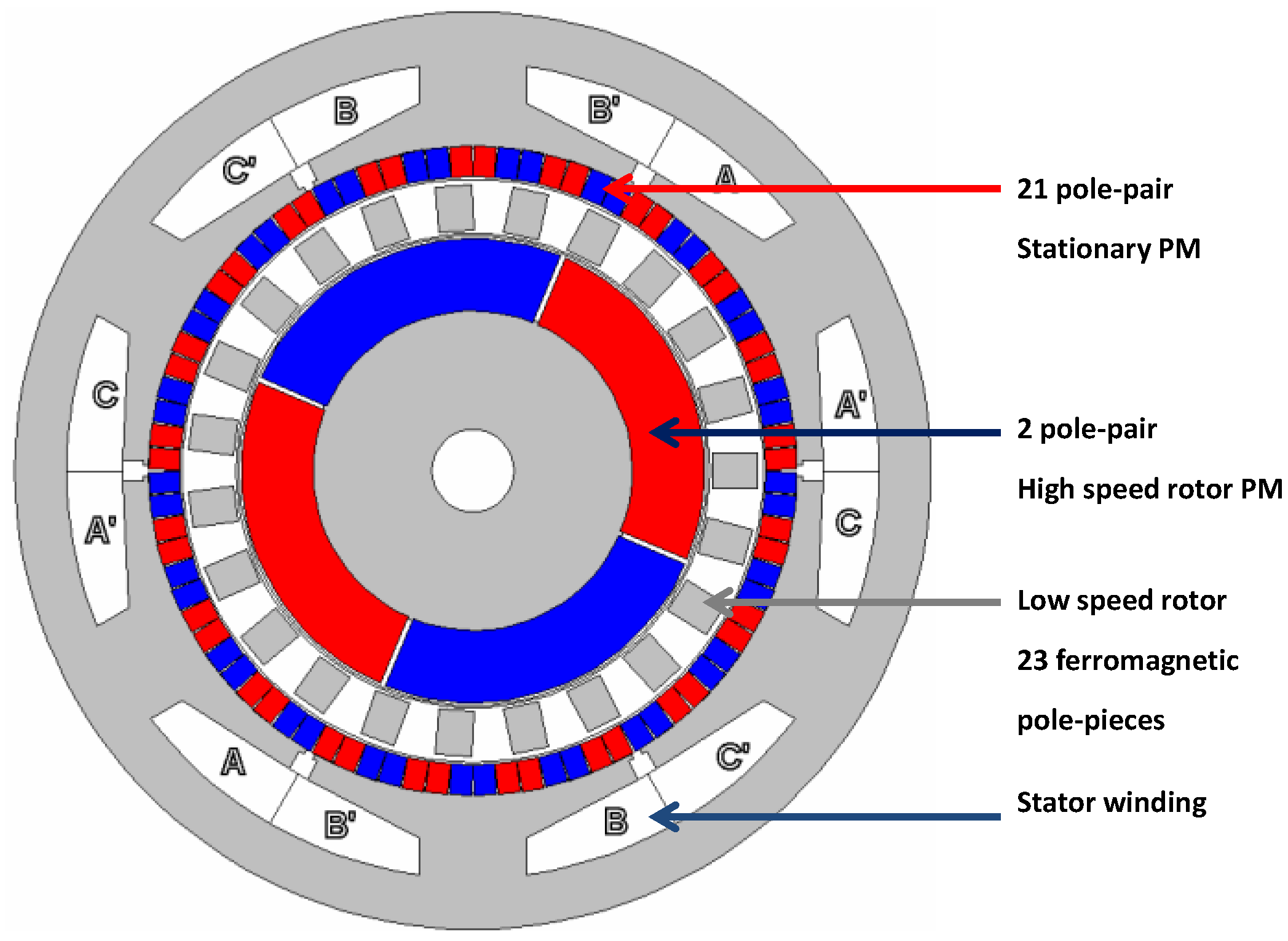
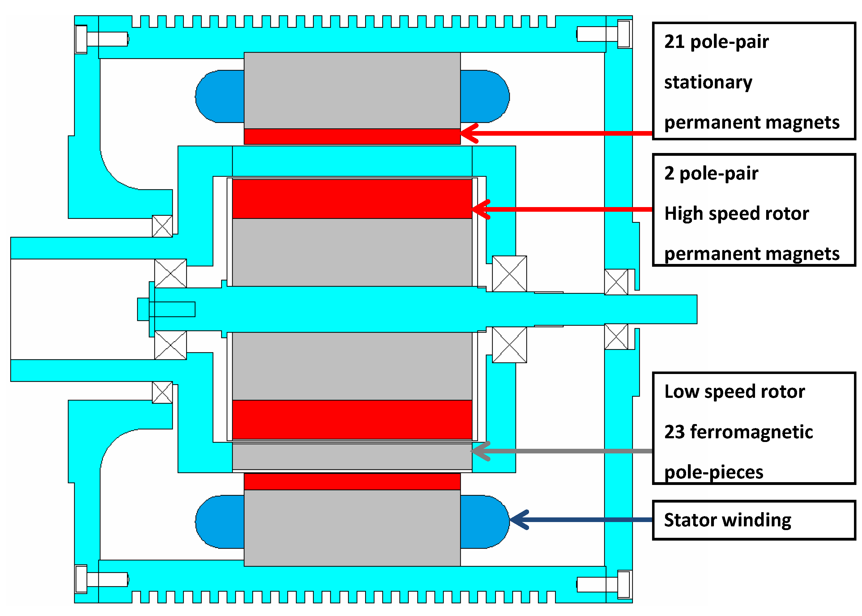
Figure 1 and
Figure 2 show the schematic of a PDD design. The electromagnetic torque is produced by the interaction of the 2 pole-pair permanent magnets (
ph = 2) on the high-speed rotor (HSR) with the currents in the stator winding. This torque is transmitted to the low-speed rotor (LSR), with a gear ratio
Gr =
ns/
ph, by the interaction of the 21 pole-pair (
pl = 21) stationary permanent magnets and the 21st space harmonic, which results from the modulation of the 2 pole-pair magnetic field on the HSR by the 23 (
ns = 23) ferromagnetic pole-pieces of the LSR.
Figure 1.
Radial cross-section of the Pseudo Direct Drive (PDD).
Figure 1.
Radial cross-section of the Pseudo Direct Drive (PDD).
Since the torque is transmitted to the load through a relatively low stiffness magnetic gear, speed and position oscillations are present with conventional PI speed control and better control strategies are required. In addition, although the load is connected to the LSR, accurate position information about the HSR is also required for electronic commutation purposes. Inferring one rotor speed/position to another through the gear ratio alone is not possible due to the factor that the angular displacement between the two rotors varies with transmitted torque.
Furthermore, overload protection is a significant advantage of a PDD, since when subjected to a load torque greater than its pull-out torque, it should harmlessly slip. However, this may lead to a pulsating torque which can induce noise and vibration. Although this may not result in any physical damage, the time taken for the machine to recover and resume normal operation after the transient overload torque disappears, will depend on how fast the slip can be detected and how the control strategy adapt when the transient overload torque occurs [
6].
Figure 2.
Axial cross-section of the PDD.
Figure 2.
Axial cross-section of the PDD.
The servo control which includes two inertias connected by a compliant mechanical coupling has been studied in [
7,
8,
9]. It is shown that the ratio of load inertia to motor inertia directly affects the performance of the controller in terms of suppressing resonance oscillations in the load. A drive train composed of a motor and load connected through a 1:1 magnetic coupling, where the inertia ratio is close to unity, has been reported in [
10,
11]. Since the magnetic gear is far more (mechanically) flexible than a classical mechanical coupling and has medium torsional stiffness, an integral proportional (IP) controller is employed to reduce the speed oscillations on the load. In contrast the PDD drive train contains not only a low stiffness coupling but also a gearing mechanism which has a significant influence on the damping and the inertia ratio between the two rotors.
Previous work on the PDD control has been reported by Wang and Atallah in [
12] where two types of controllers, a PI and a state feedback (SFBK) controller, have been studied. It has been shown that, due to the magnetic gearing and lack of damping, torsional oscillation will result with the PI controller, causing abrupt speed and position transients, increased copper loss in the motor, and poor overall performance. The SFBK tuned according to [
13] has improved the performance, but not to the point where the oscillations are completely removed. An observer based SFBK controller has been applied to the PDD control in [
14,
15]. The feedback gains have been tuned using Genetic Algorithm (GA) [
16] to satisfy the integral time multiplied by absolute error (ITAE) criterion given by Equation (1). This performance index has the advantages of producing smaller overshoots and less oscillation than the integral of square error (ISE) or integral of the absolute error (IAE). It is shown that the proposed control technique has significantly reduced torsional oscillations in the output.
This paper performs complex frequency domain analyses of the PDD in closed loop. The state-space equations of the closed loop system with three candidate controllers, viz., PI, IP and SFBK are established and the resulting eigenvalues are computed and presented in the s-plane. A relationship between the poles/zeros and the system states is identified, and the effect of the controller structure on the system damping is quantified. This provides an in-depth understanding of how the controller structure and control/load parameters influence the system damping. An experimental rig has been developed and the simulated results were validated through systematic experimental tests.
2. Modelling of Pseudo Direct Drive
In a PDD, the HSR and LSR are magnetically coupled and the mechanical load is applied to the LSR. The torque is transmitted from the HSR to the LSR. The equations that govern their motion are as follows
where
ωh,
Jh,
Bh are the angular speed, the moment of inertia and the viscous damping of the HSR respectively,
ωo,
J,
Bo are the angular speed, the combined inertia of the LSR
Jo and the load
JL, and the combined damping coefficient of the LSR and the load respectively.
Gr=
ns/
ph is the magnetic gear ratio, where
ph is the number of pole-pairs on the HSR and
ns is the number of ferromagnetic pole pieces on the LSR.
TL is the load torque,
Tmax is the pull-out torque reflected to the LSR and
Te is the electromagnetic torque produced by the q-axis current
iq, when a surface-mounted magnet topology is employed for the HSR, and is given by
The stator flux-linkage is
φm. The electromagnetic torque is transmitted to the LSR via an equivalent magnetic spring with a stiffness given with respect to LSR as
The referred angel
θe is defined as the angular displacement between the HSR and the LSR, given by
The angular positions of the HSR and LSR are given by
θh and
θo respectively. From Equation (5) it can be shown that the system is stable when the stiffness
Kes is positive,
i.e., only when
θe is within the range
![]()
,
n is an integer number.
The equivalent inertia of the HSR with the magnetic gear seen by the LSR is obtained by
The damping coefficient
Kd is associated with the referred angular speed
![]()
between the HSR and LSR due to eddy current loss in the HSR and iron loss in the LSR. Since the damping effect,
Kd is very small it is assumed that
Kd = 0. The nonlinear transfer function block diagram of the PDD is shown in
Figure 3. The linearized representation of the PDD transfer function is shown in
Figure 3.
Figure 3.
The transfer function block diagram
Figure 3.
The transfer function block diagram
The transfer function of the mechanical system in
Figure 3 becomes [
12]
The un-damped natural frequencies
ωn and
ωa of the pole and zero pairs in Equation (8) are referred to as the resonant and anti-resonant frequencies [
17]. As can be seen, both transfer functions contain an un-damped mode, and hence oscillation may occur if this mode is not adequately damped. With
Je >>
J,
ωn =
ωa oscillations occur on the LSR at the resonant frequency
ωn but are filtered by the relatively large equivalent inertia seen by the HSR. With
Je <<
J, the resonant frequency given by
![]()
is dictated by the equivalent inertia and the equivalent stiffness.
Table 1.
PDD parameters.
| Jh(kgm2) | 3.8 × 10⁻³ |
| Jo(kgm2) | 2.5 × 10⁻³ |
| JL(kgm2) | 0.28 |
| Rp(Ω) | 2 |
| φm(Wb) | 0.59 |
| Tmax(Nm) | 135 |
| Ld(H) | 32.6 × 10⁻³ |
| Lq(H) | 32.6 × 10⁻³ |
| Bh(Nms/rad) | 1.0 × 10⁻⁴ |
| Bo(Nms/rad) | 2.0 × 10⁻⁴ |
| kd(Nms/rad) | 0.5 × 10⁻⁴ |
| ωomax(rad/s) | 30 |
| ωhmax(rad/s) | 345 |
| Udc(V) | 435 |
| iq max(A) | 9 |
The electrical dynamics of the PDD is similar to that of the conventional surface mounted brushless permanent magnet machine. They are given in term of the d-q axis currents by
Ld and
Lq are the d- and q-axis motor inductances, respectively;
Rp is the motor winding resistance per phase;
Kt and
Ke are the motor torque and back-emf constants, respectively.
vd and
vq are d- and q-axis voltages, respectively, and
ωe =
p ×
ωh is the electric angular frequency of the PDD. The parameters of the PDD are given in
Table 1.
3. Complex Frequency Domain Analysis of the Pseudo Direct Drive
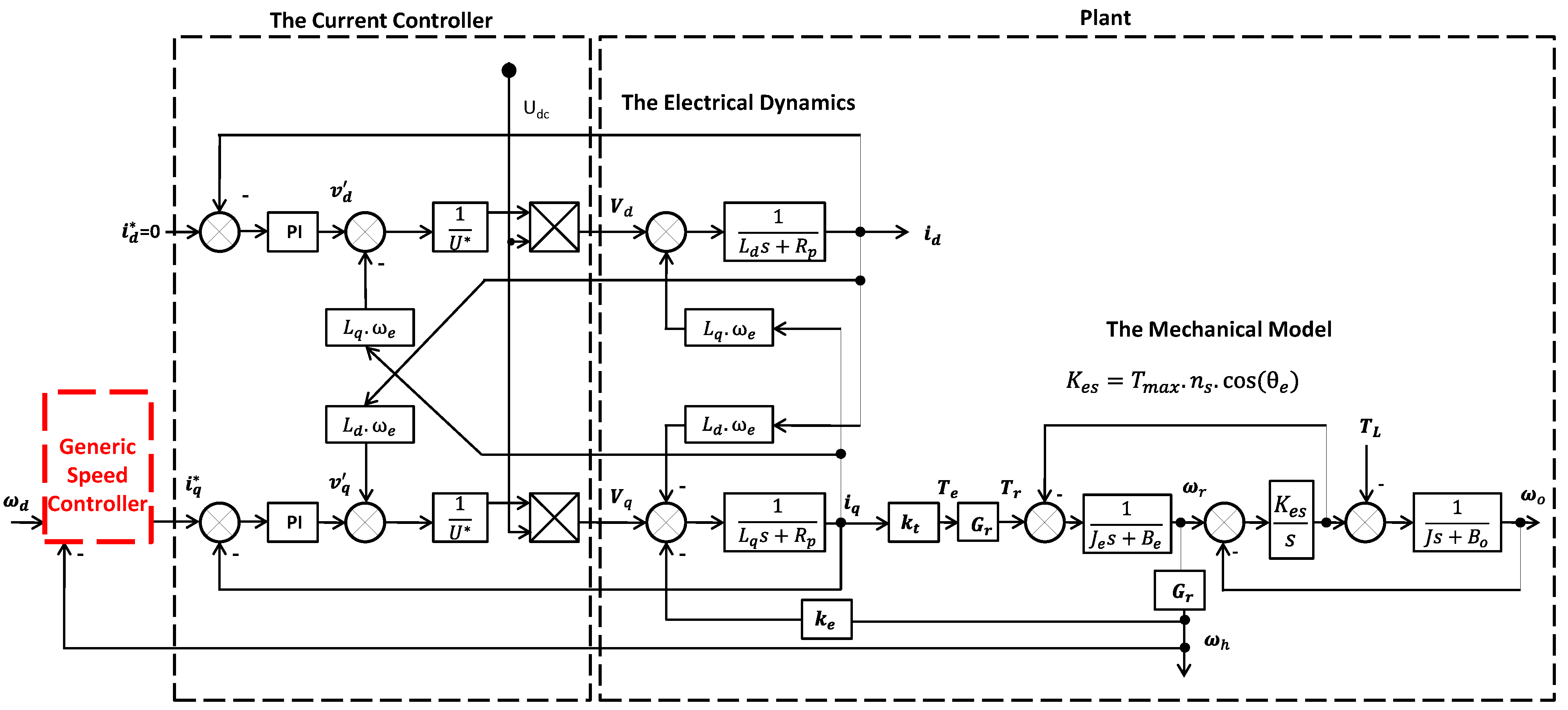
Figure 4 represents the PDD under a generic speed controller. The field oriented control is used to control the currents in the d-q axis reference frame. The gains of the PI current controllers for
id and
iq are designed for a bandwidth of 400 Hz. The generic speed controller represents one of the following controllers: PI, IP or SFBK controller. A derivation of the system states in closed loop is obtained for each controller structure. The gains of the three speed controllers have been tuned with GA in Simulink to satisfy the ITAE performance index defined in [
15] against a complete closed-loop model comprised of the PDD dynamics, a pulse width modulation (PWM) block, the current controllers and the speed controller. The set of gains obtained by GA are used for the frequency domain analysis and time domain simulations as well as for validation of the system in real time implementation.
Figure 4.
Schematic of the Pseudo Direct Drive under a speed controller.
Figure 4.
Schematic of the Pseudo Direct Drive under a speed controller.
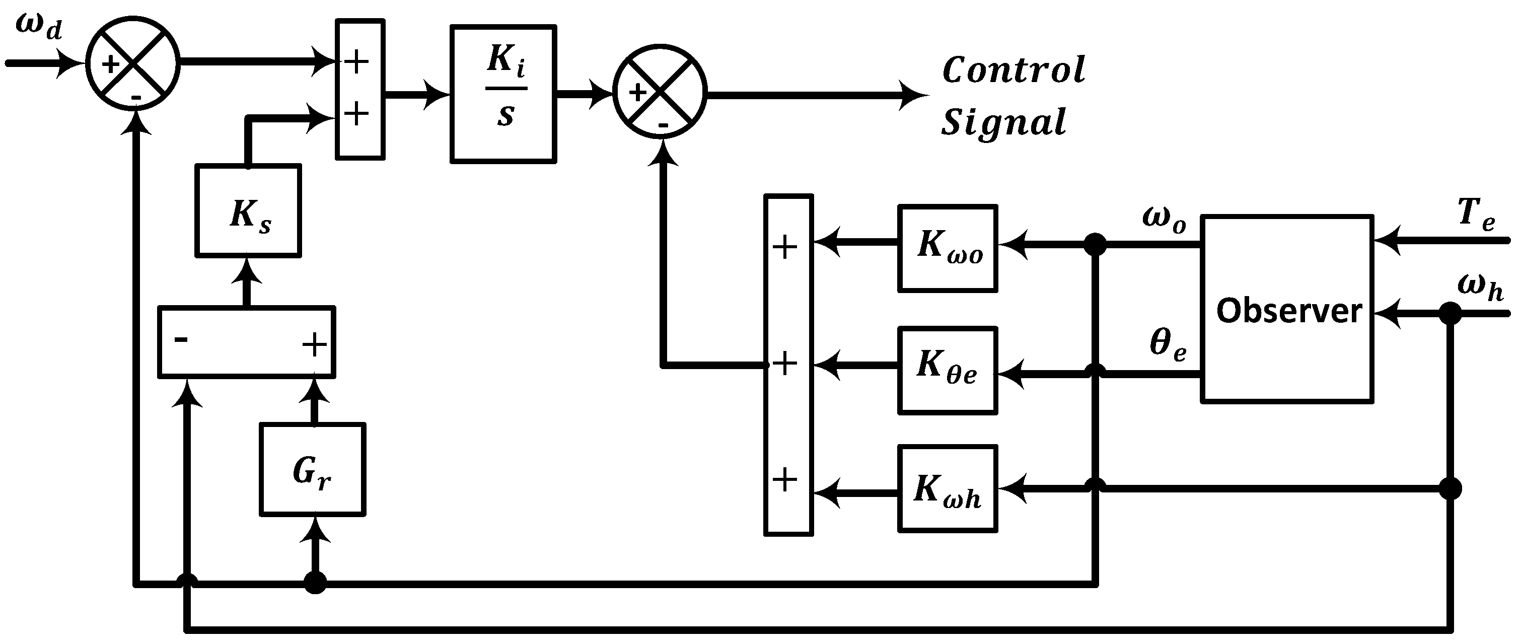
The SFBK structure described in
Figure 5 represents one of the generic controllers of the system in
Figure 4, where the feedback signal
ωo is taken from the observer. The controller has four proportional gains and one integral gain. Three proportional gains are related to the feedback of the system states, viz., the speed of the HSR,
ωh, the speed of the LSR,
ωo and the referred load angle
θe. The fourth gain
Ks is employed to correct any deviation from synchronization that may occur in the speeds of the two rotors. The gains obtained by GA tuning are given in
Table 2, full details of GA tuning and implementation of this system is provided in [
14].
Table 2.
Gains of the implemented controllers.
Table 2.
Gains of the implemented controllers.
| Proportional Gain(s) |
|---|
| PI | Kp = 0.8386 |
| IP | Kp = 0.3469 |
| SFBK | Kwh = 1.765
Kwo = 1.699
Kθe = 9.7856
Ks = 0.1122 |
| Integral Gain | ITAE |
| PI | Ki = 6.863 | 2.03 |
| IP | Ki = 235.01 | 1.80 |
| SFBK | Ki = 5132.8 | 1.67 |
| Current Controller Gains |
| Kpq = Kpd = 81.93 |
| Kiq = Kid = 5026.5 |
Figure 5.
State Feedback Controller Structure.
Figure 5.
State Feedback Controller Structure.
In the frequency domain analysis, the observer dynamics are neglected, as the estimation error of the observer is very small compared to direct measurements. The observer has been linearised around the rated torque of 100 Nm resulting in
θe ≈ 0.8 rad. The design of the observer and sensitivity analysis has been reported in [
15].
The closed-loop system may be represented as follows
where
X and
U are the vectors of the state variables and inputs, respectively, and
f(
X, U) is the vector of the non-linear functions of
X and
U [
18]. They are given by
The components of the vector function
f(
U, X) for the SFBK controller are given in Equation (12), where
xD and
xQ are the internal states of the d- and q-axis current PI controllers, respectively;
x is the internal state of the SFBK speed controller.
Kpd and
Kpq are proportional gains of the d- and q-axis current controller, respectively;
Kid and
Kiq are the integral gains of the d- and q-axis current controllers, respectively. For a given value of the inputs
ωd it can be shown that in steady state, the operating points of the state variables are obtained as
id0 = 0,
xD0 = 0,
ωh0 =
ωd,
x0 =
iq0, the DC supply voltage,
Udc, only varies over a small range so the ratio
![]()
≈ 1.
![]()
is set to zero for maximum torque per Ampere operation since flux weakening is not required.
The state-space equation in Equation (11) can be linearized at the steady-state operating point (
X0,
U0), and the Jacobian matrix of Equation (12) is obtained as follows
The matrices
A,
B,
C and
D are given by
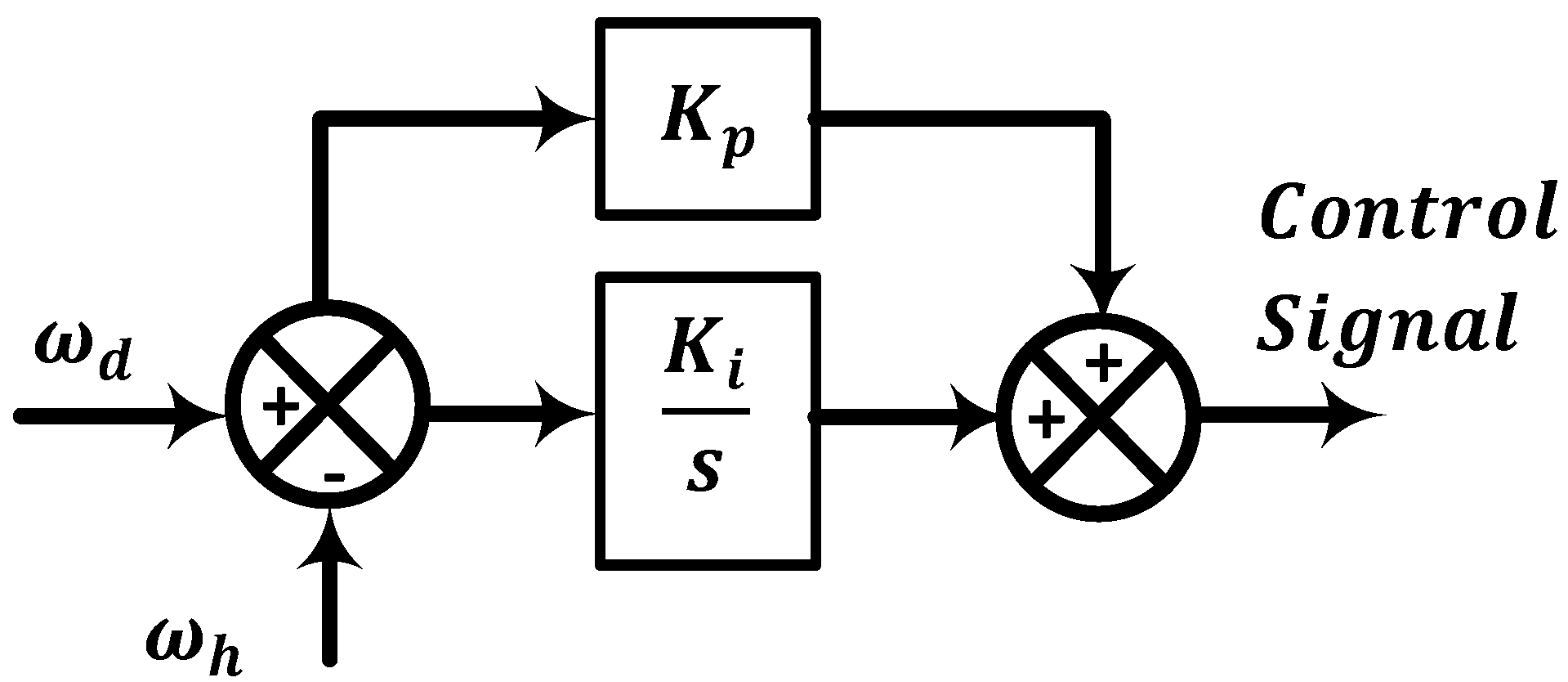
The state-space equations of the drive system with the IP and PI structures shown in
Figure 6 and
Figure 7 are obtained by replacing the generic controller of the system in
Figure 4. The speed and position feedback signals are directly measured from a resolver mounted on the HSR.
Figure 6.
Integral and proportional controller structure.
Figure 6.
Integral and proportional controller structure.
Figure 7.
Proportional and integral controller structure.
Figure 7.
Proportional and integral controller structure.
A detailed derivation and the resulting equations of the PI and IP controllers are given in [
19].
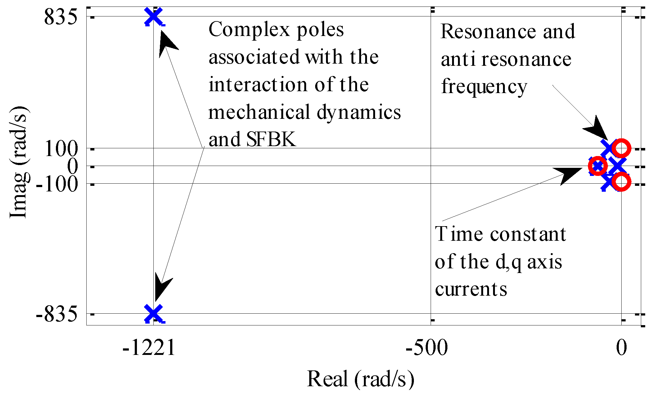
From the linearized state-space equations, closed-loop transfer functions between the speed demand and speed output can be obtained and their poles and zeros are explicitly plotted in
Figure 8, where the poles are marked in “x” and zeros in “o”. The overlapping poles on the negative real axis close to the origin are related to the electric time constant of the d- and q- axis currents. Their effects are cancelled by two zeros through the pole/zero cancellation in the current controller design. The complex conjugate poles-pair with great negative real is associated with the interaction of the SFBK control with the mechanical dynamics of the PDD. However, the dominant pole-pair of the closed loop system is the complex conjugate pole-pair with far less negative real and the imaginary close to the torsional resonant frequency given in Equation (8). The complex pair of zeros, representing the anti-resonant frequency, is very close to the dominant poles. The load torque, motor/load inertia, gear ratio, magnetic damping and the stiffness of the magnetic gear influence the location of the dominant pole-pair and hence the dynamic behaviour of the closed loop drive system.
Figure 8.
Poles and zeros distribution for
![]()
.
Figure 8.
Poles and zeros distribution for
![]()
.
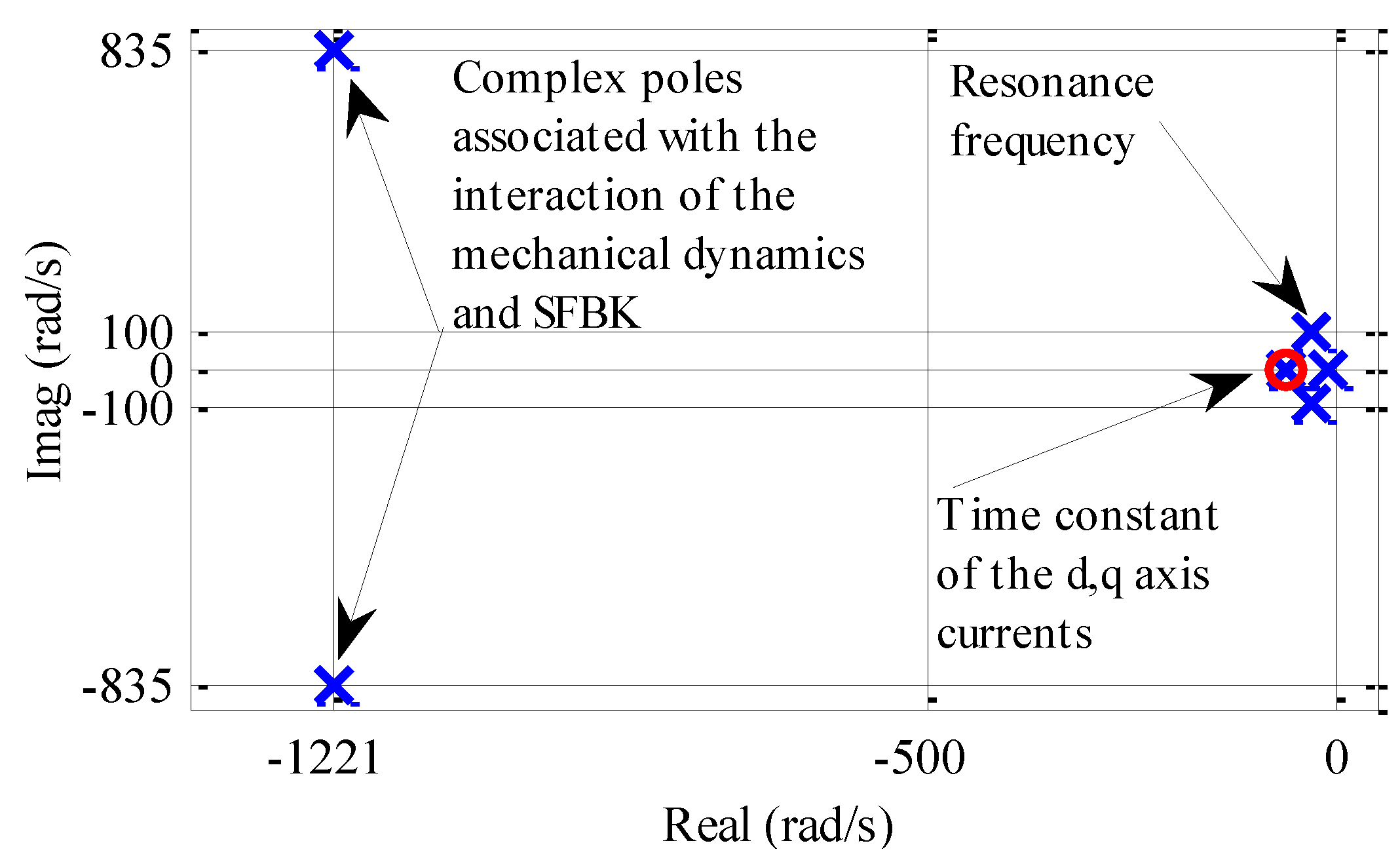
Figure 9 shows the poles/zeros of the transfer function
G2(
s), where the distribution is similar to
G1(
s) in
Figure 8 except the zeros at the anti-resonant frequency is not present in
G2(
s) in accordance with Equation (8). Pole-zero distributions associated with IP and PI controllers have a similar pattern and therefore not plotted. Their dominant poles are also associated with the torsional resonance. In order to compare the performance of three optimally designed controllers for suppression of the torsional oscillation, the dominant poles which result from the three controllers are plotted together in the same s-plane.
Figure 9.
Poles and zeros distribution for
![]()
.
Figure 9.
Poles and zeros distribution for
![]()
.
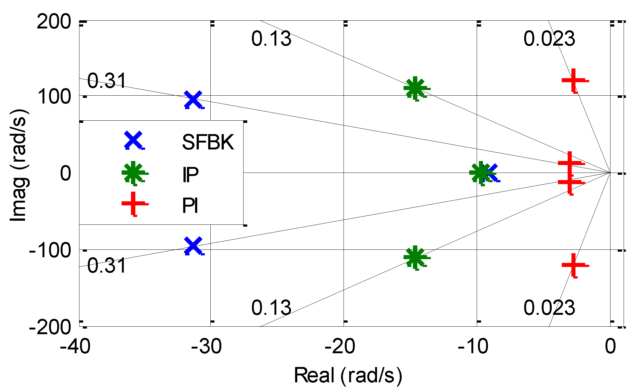
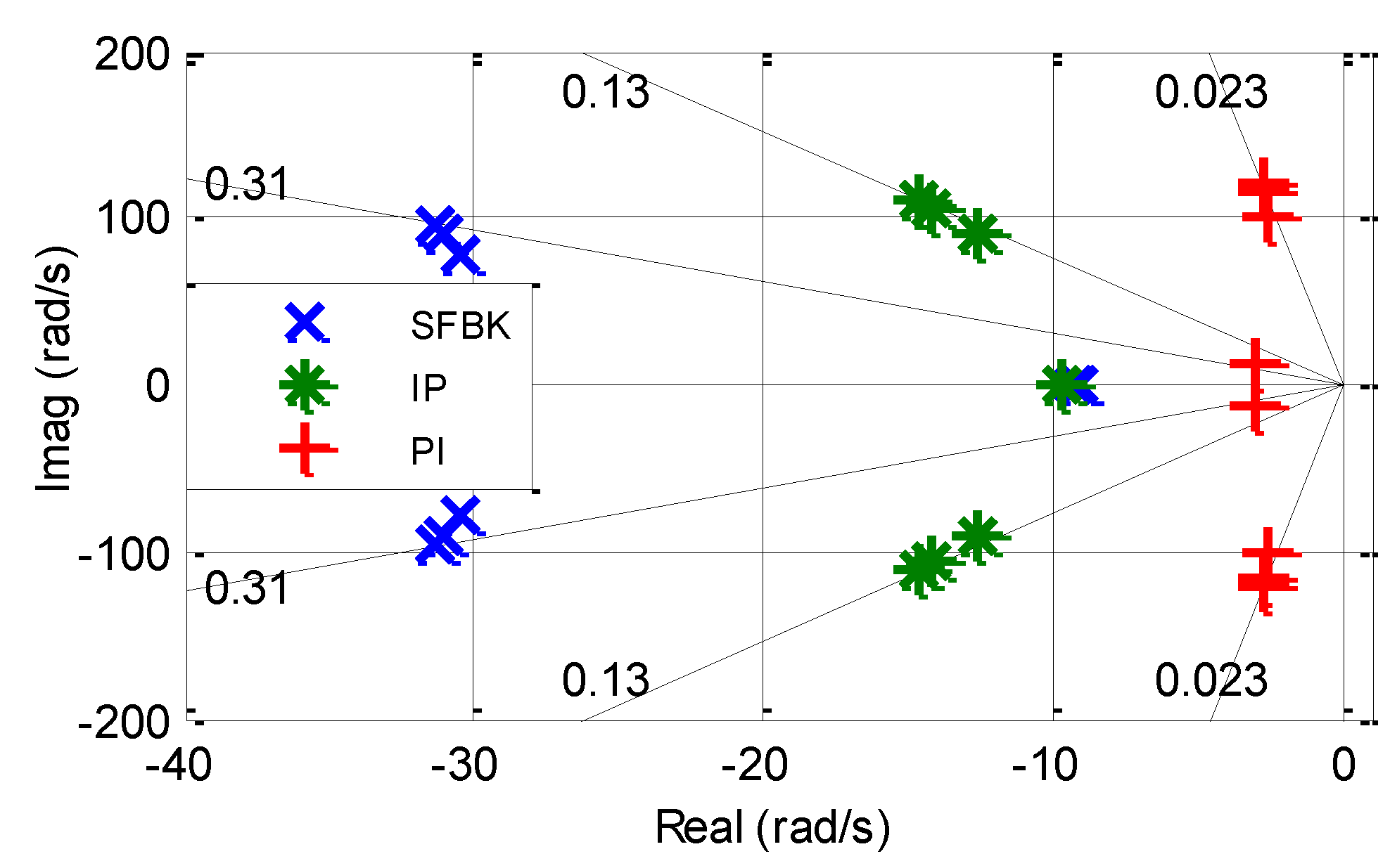
Figure 10 shows the dominant poles of the three controllers in closed loop. It is evident that much more damping has been achieved with the SFBK controller. By using a well-tuned controller the poles are placed such that the ITAE is minimised, hence optimum damping and bandwidth is achieved. This also confirms the time domain simulation results that show the system having achieved more damping by reducing the oscillations in the output.
In contrast, the PI and IP control structure results in the dominant poles being close to the imaginary axis and hence much lower damping. The IP can only achieve a maximum damping of ζ = 0.13 and the PI exhibit very poor damping of ζ = 0.023, being an order of magnitude lower in comparison with the damping obtained by the SFBK controller. Hence both the PI and IP structures are not capable of improving the damping of the dominant pole-pair associated with torsional resonance in the PDD dynamics as compared to the SFBK.
Figure 10.
The dominant poles for all controllers.
Figure 10.
The dominant poles for all controllers.
Figure 11 shows the loci of the dominant pole-pair with increase in the load torque
TL from 0 to the maximum load in 3 steps (0 Nm, 50 Nm, 100 Nm). As will be seen, the SFBK control exhibits robust performance against the load torque variations as the system damping increases and bandwidth is nearly constant with increase in load torque. An increase in the load torque seems to slightly increase the system damping under the PI albeit its damping is still significantly low. The load torque increase did not affect the system damping under IP controller. However, the bandwidth has been reduced by more than 15% with the load torque increase.
Figure 11.
Loci of dominant poles with load torque variation for PI, IP and SFBK controllers.
Figure 11.
Loci of dominant poles with load torque variation for PI, IP and SFBK controllers.
Figure 12 shows the dominant poles of the three controllers when subjected to a load inertia variation, where the load to motor inertia ratio
R is given by
By changing the load inertia in four steps, R varies from to 0.25, 0.56, 1 to 2. It can be seen that with the PI control, both the system damping and control bandwidth decrease with decrease in the inertia ratio. The damping and bandwidth are still very poor even when the ratio is increased to R = 2.
The dominant poles of the closed loop system under the IP control show a high level of sensitivity to the inertia variation, and any decrease in R results in significant reduction in the damping. More specifically, the figure shows that the system damping can be reduced by an order of magnitude and the bandwidth by more than half when R is varied from 0.56 to 0.125. Also the bandwidth may be reduced significantly when R is increased to R = 2 as the two real poles representing the d-q axis currents are pushed further towards the origin reducing the system bandwidth as shown with a green arrow.
Figure 12.
Loci of dominant poles with load inertia variation for PI, IP and SFBK controllers.
Figure 12.
Loci of dominant poles with load inertia variation for PI, IP and SFBK controllers.
The SFBK controller is much robust than the other two controllers. It has been seen that the lowest damping which results when R = 0.125 is 0.14, is still more than an order of magnitude greater than the damping achieved by the PI control, and much greater than that of the IP control. Moreover, the SFBK control bandwidth is insensitive to the inertia ratio variations. Therefore, the system with the SFBK control exhibits more robustness towards parameter variations.
4. Experimental Results and Discussion
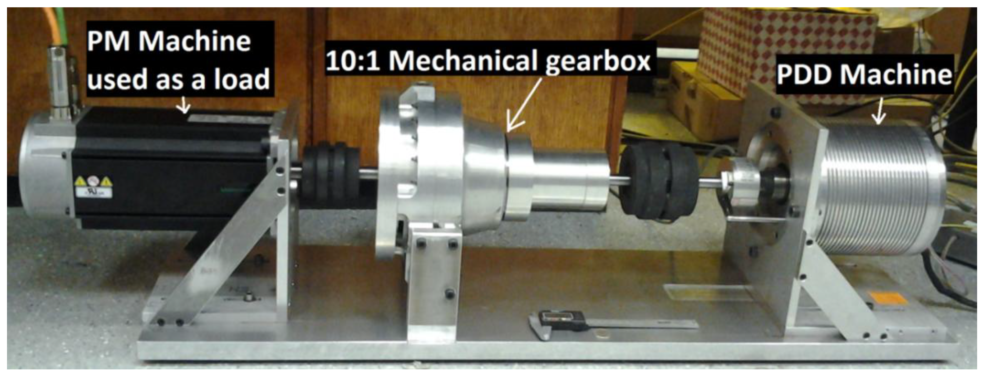
The findings of the above analysis have been validated with a specially designed and built test rig as shown in
Figure 13. The PDD control, including the PI, IP and, the SFBK and observer, is implemented in a dSPACE real-time hardware platform at sampling frequency of 10 kHz with PWM of the drive machine set at 8 kHz. The resulting torque command is fed to a commercial drive in torque control mode. The PDD operates in speed control mode and is loaded by the PM machine in torque control mode. The PM load machine is coupled to the PDD via a 10:1 inline gear box in order to provide sufficient load torque for the PDD operation. The speed/position of the HSR is measured with a resolver, and an encoder is placed on the LSR for the purpose of monitoring its speed/position only. The load torque is inferred from the current in the load machine and the relationship between the current and the torque has been determined using torque transducer.
Figure 13.
The Pseudo Direct Drive test Rig.
Figure 13.
The Pseudo Direct Drive test Rig.
To test the speed response with one of the controllers PI, IP, and SFBK, the LSR of the PDD is accelerated from standstill to 100 rpm, and at 2 s a load torque of 100 Nm is applied by the load machine for duration of 3 s. Simulated and experimental results are shown in
Figure 14,
Figure 15 and
Figure 16 for the three controllers together with the load torque waveform.
Figure 14 shows the simulation and measured PDD responses under the PI control. It can be seen that whilst the simulated and measured speed responses agree very well, undesirable oscillations which result from the poor damping in both rotor speeds are very significant.
Figure 14.
PDD speed responses under PI. (a) Simulated; (b) Measured.
Figure 14.
PDD speed responses under PI. (a) Simulated; (b) Measured.
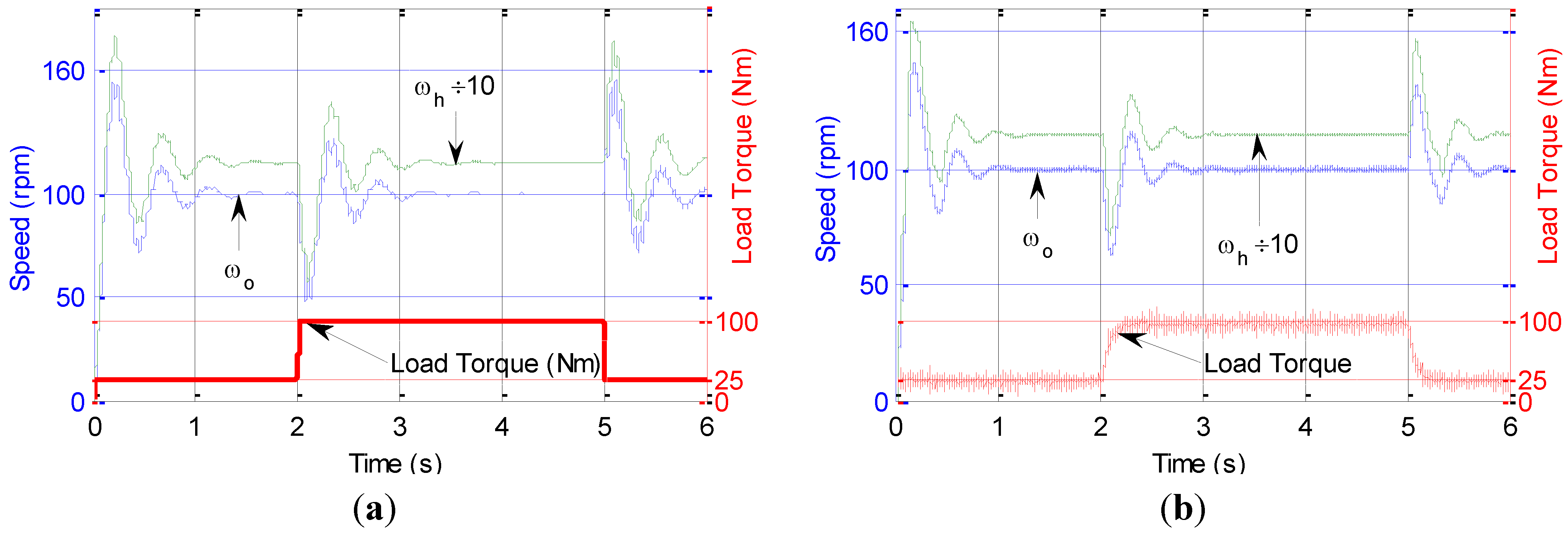
Figure 15 shows the PDD speed responses under the IP controller, where an improved speed tracking and disturbance rejection is achieved in comparison with the PI control. However, oscillations still appear when the load is applied or removed.
Figure 15.
PDD responses under IP. (a) Simulated; (b) Measured.
Figure 15.
PDD responses under IP. (a) Simulated; (b) Measured.
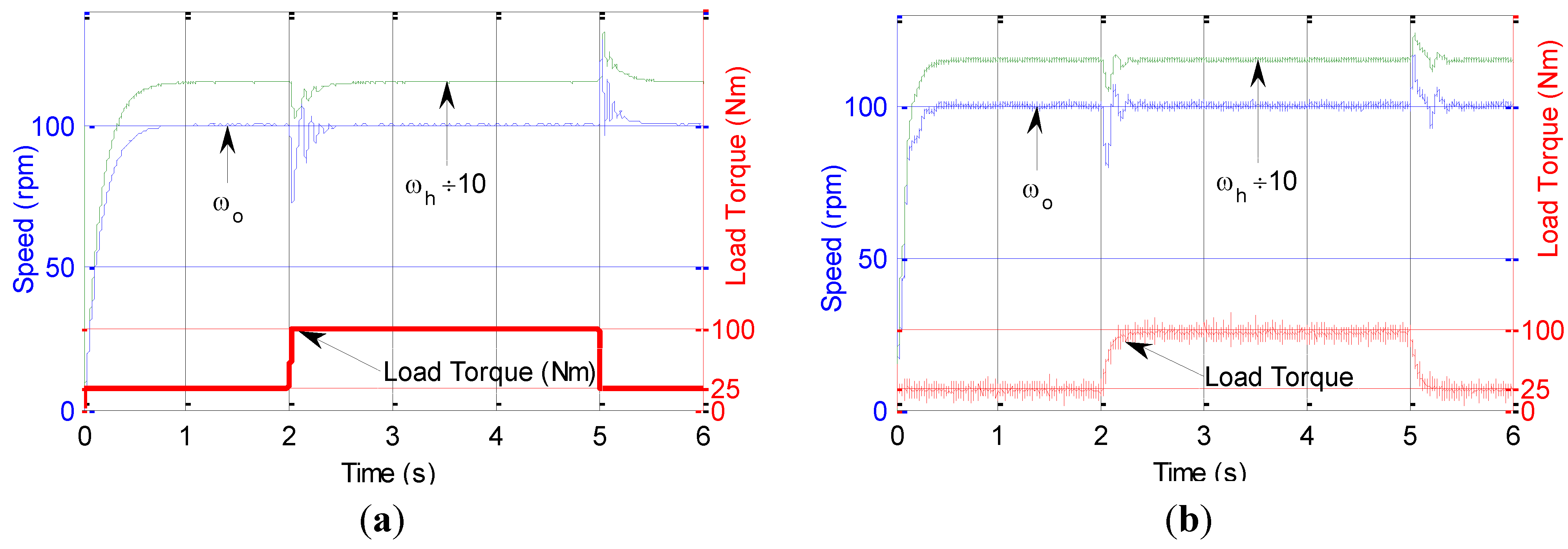
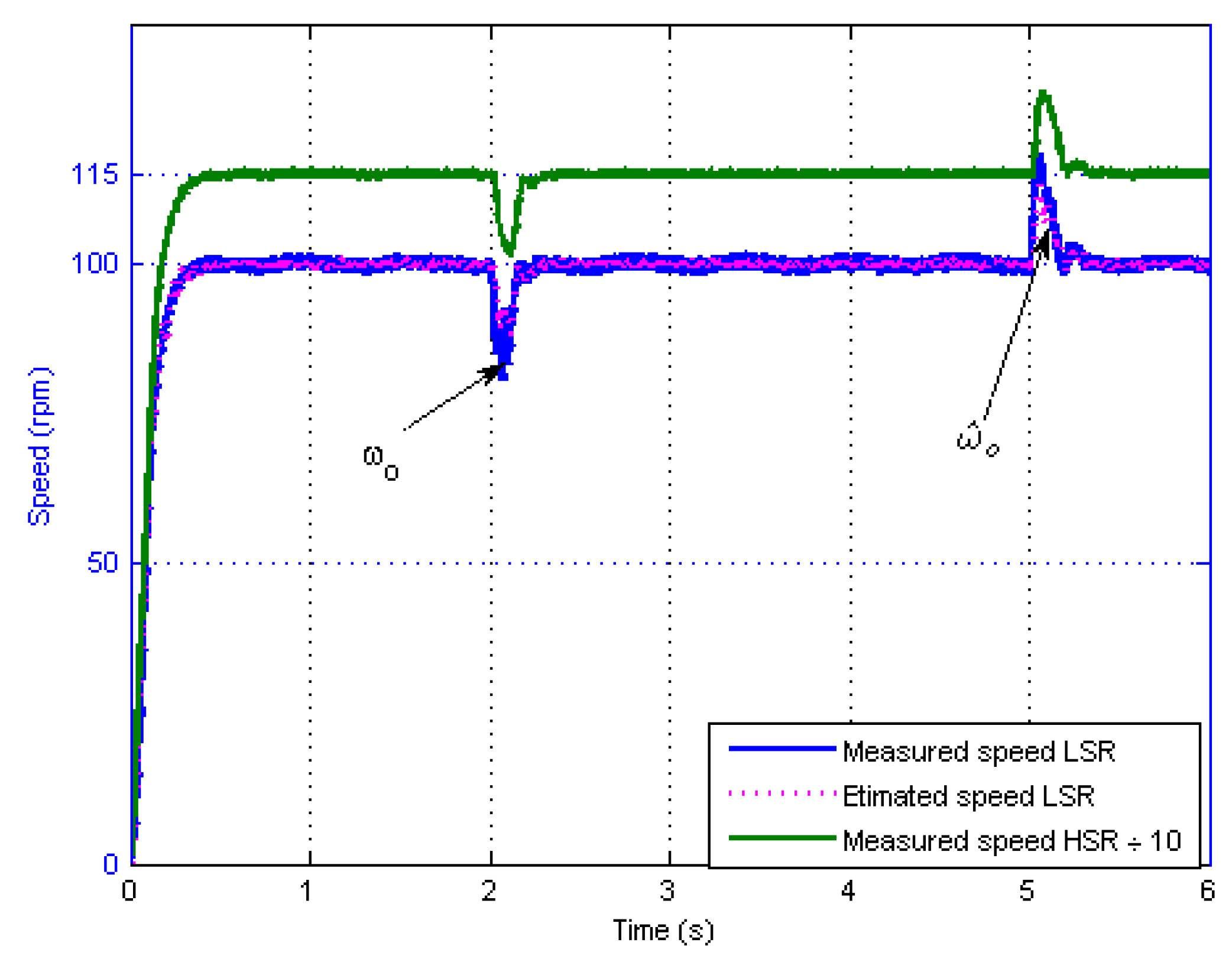
Figure 16 shows the response of the PDD under SFBK control, where the controller exhibits good disturbance rejection and speed tracking, with no visible oscillations in the output.
The SFBK is realized using a reduced order observer.
Figure 17 shows the measured speed
ωo against the estimated speed
![]()
from the reduced order observer in real time.
Figure 16.
PDD responses under SFBK. (a) Simulated; (b) Measured.
Figure 16.
PDD responses under SFBK. (a) Simulated; (b) Measured.
Figure 17.
Measured and estimated LSR and HSR speeds.
Figure 17.
Measured and estimated LSR and HSR speeds.
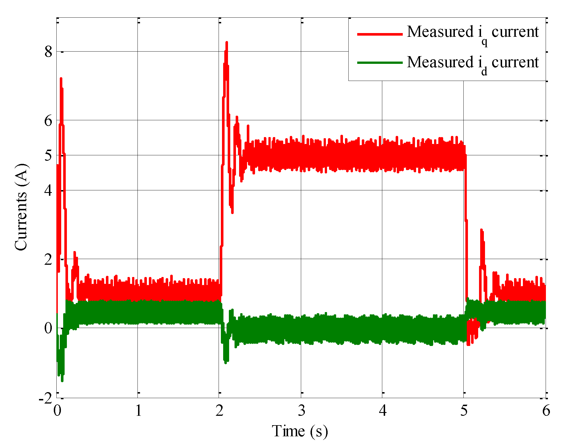
Figure 18.
Measured currents iq and id under PI control.
Figure 18.
Measured currents iq and id under PI control.
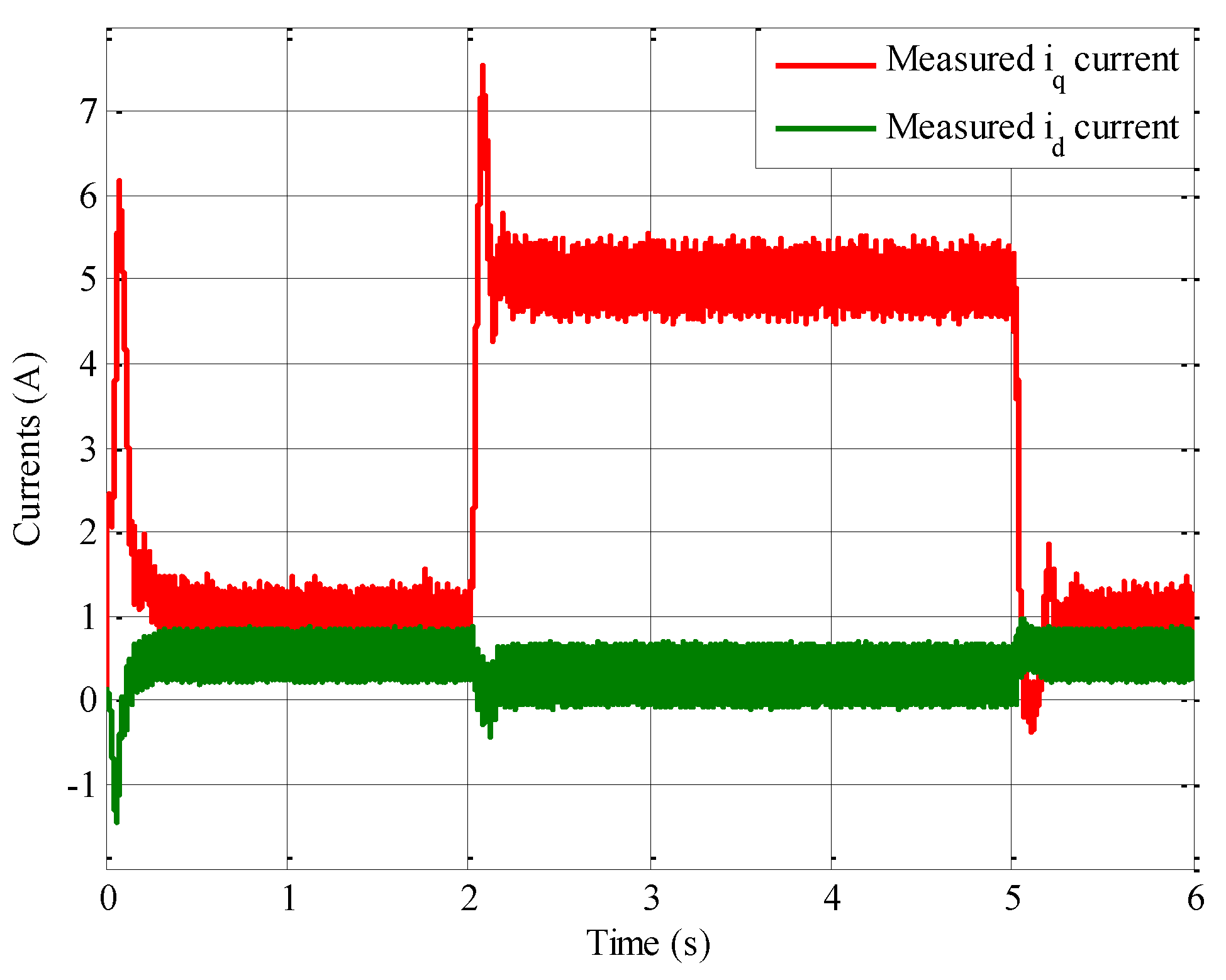
Figure 19.
Measured currents iq and id under IP control.
Figure 19.
Measured currents iq and id under IP control.
Figure 20.
Measured currents iq and id under SFBK control.
Figure 20.
Measured currents iq and id under SFBK control.
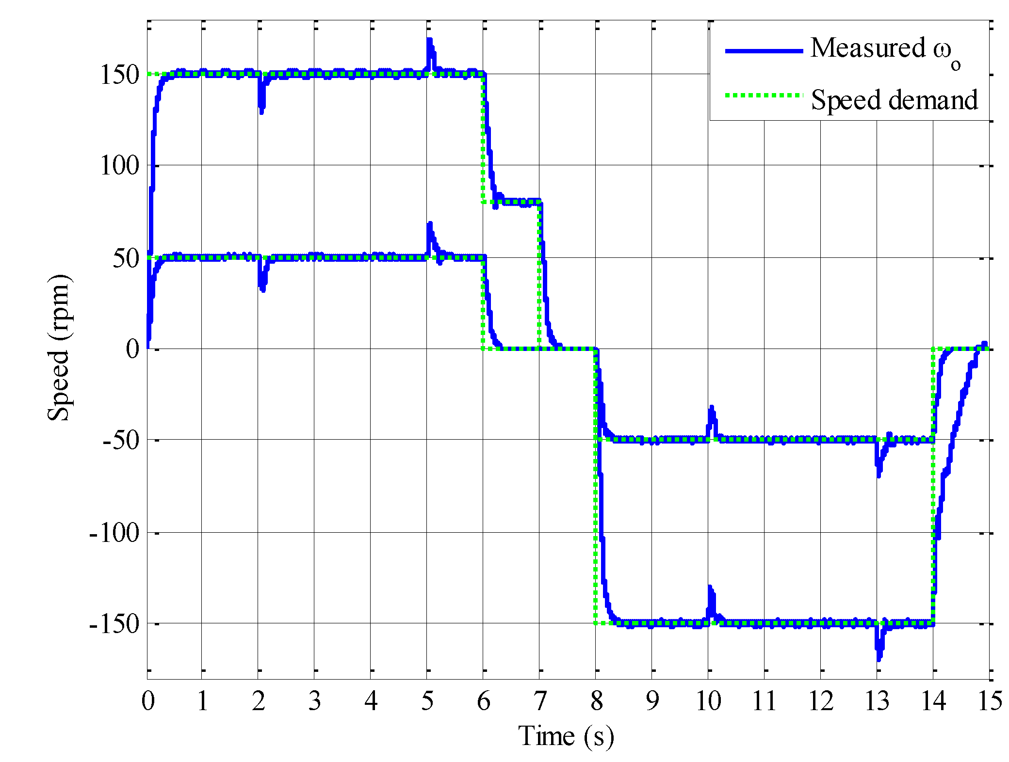
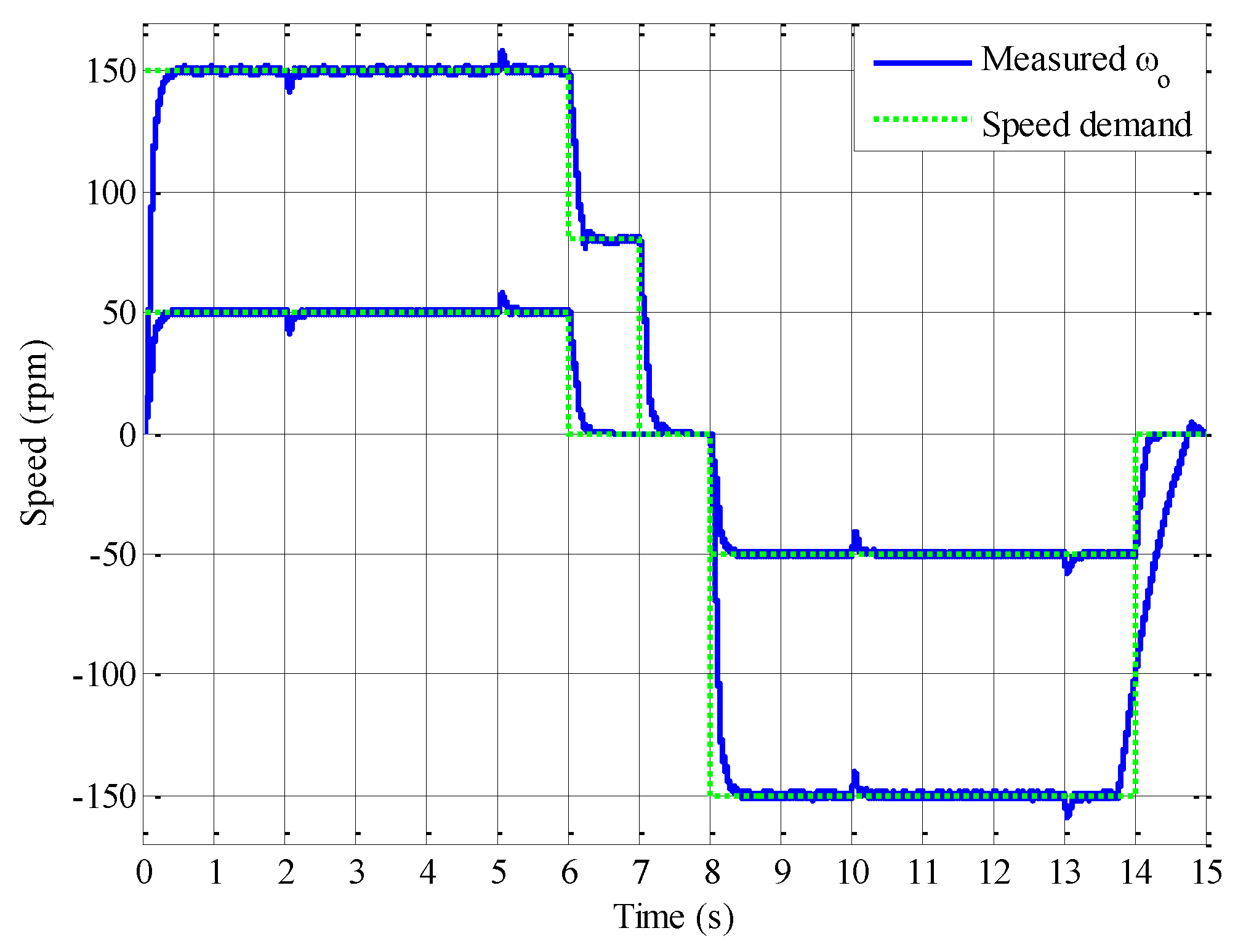
Figure 21 and
Figure 22 show the PDD operated at ±50 and ±150 rpm with load torque of 100 and 50 Nm applied to the LSR from time 2 to 5 s and 10 to 13 s respectively.
Figure 21.
LSR under SFBK control and 100 Nm load torque.
Figure 21.
LSR under SFBK control and 100 Nm load torque.
Figure 22.
LSR under SFBK control and 50 Nm load torque.
Figure 22.
LSR under SFBK control and 50 Nm load torque.


 , n is an integer number.
 between the HSR and LSR due to eddy current loss in the HSR and iron loss in the LSR. Since the damping effect, Kd is very small it is assumed that Kd = 0. The nonlinear transfer function block diagram of the PDD is shown in Figure 3. The linearized representation of the PDD transfer function is shown in Figure 3.

 is dictated by the equivalent inertia and the equivalent stiffness.


 ≈ 1.
≈ 1.  is set to zero for maximum torque per Ampere operation since flux weakening is not required.


 .
.
 .
.


 from the reduced order observer in real time.


