1. Introduction
Although several advanced control methods have been proposed in the literature, it is an incontestable fact that the Proportional-Integral-Derivative (PID) control is by far the most used control method both in industry and academia [
1,
2,
3]. In many advanced part of industry, such as process control, power systems, motion control and robotics, the majority of the controllers are still simple PID control systems due to their simple usage, ease of understanding, and effective performance [
4,
5]. Since the stability and performance of a PID-based control system may drastically change by the controller gains,
i.e., proportional, integral and derivative control gains, several different tuning methods/algorithms have been proposed for PID controllers [
5]. However, the performance of many practical applications, such as motion control, is limited by inappropriate PID settings. It is a very serious problem that an important part of PID controllers lacks the desired performance due to their poor tuning, and this turns back as an increased cost [
2].
Ziegler-Nichols (ZN) is one of the most widely used PID tuning methods in the literature [
4,
6,
7]. It requires many trials on the system and does not provide satisfactory performance all the time. It generally produces big overshoots, and the performance of systems decreases with varying system parameters such as inertia variations in servo systems [
4]. Several different modifications and algorithms have been proposed to improve ZN; however, their performances are still limited in practical applications [
6,
8,
9]. In the proposed conventional PID tuning methods, there is generally a trade-off between the robustness and performance of control systems,
i.e., increasing the robustness degrades the performance and
vice versa [
10]. For instance, a high performance PID control system was achieved in [
11], yet it was sensitive to external disturbances [
3]; however, the robustness to external disturbances was improved by tuning the PID control parameters in [
12], yet it had insufficient performance [
10].
In addition to the conventional approaches, there are more advanced and intelligent PID tuning methods and algorithms, such as Genetic Algorithm (GA), Particle Swarm Optimization (PSO), Ant Colony Optimization (ACO), Fruit Fly Optimization (FOA),
etc., in the literature [
4,
6,
13,
14,
15]. Although these methods enhance the capabilities of the conventional tuning methods, along with the complicated motion dynamics, they are very difficult to be used by the engineers in industry, students in academia, and even by most researchers.
In robotics and motion control fields, PID controllers are widely used to control the position of servo systems. The tuning of PID controllers for such systems is quite a challenging task, since they generally have nonlinear and unknown disturbances, such as friction, time-varying inertia and external load. The performance of a servo system is significantly influenced by such disturbances due to improper tuning of PID parameters. Although advanced PID tuning methods have been proposed to improve the robustness and performance of servo systems, they suffer from complexity [
8]. The need for a simple and efficient PID tuning method still remains in the literature.
This paper proposes a novel practical tuning method for the robust PID controller with velocity feed-back. The proposed controller provides that a high performance robust motion control system can be simply designed by properly tuning the conventional PID controllers. Against the conventional PID tuning methods, the proposal separately adjusts the performance and robustness, i.e., improving the robustness does not degrade the performance and vice versa. Firstly, an ideal servo system, which is linear and not influenced by disturbances, such as friction, inertia variation and external load, is considered to design the performance controller. A desired performance is easily achieved by tuning the control parameters of a PD controller. Secondly, the robustness of the servo system is improved by modifying the parameters of the PD controller and adding an I controller with velocity feed-back. In the proposed method, the performance of a servo system is not influenced by increasing the robustness, i.e., suppressing the external disturbances and parameter variations does not degrade the performance. However, the robustness of the proposed controller is limited by practical constraints such as noise and sampling period, so it cannot be freely improved in practice. A simple design method is proposed by considering practical constraints. The validity of the proposal is verified by giving simulation and experimental results.
The rest of the paper is organized as follows. In
Section 2, the proposed robust PID tuning method is briefly presented. The brief explanation, which is given in
Section 2, is sufficient to design the robust PID controller. In
Section 3, the proposed PID control gains are analytically derived by using the analogy of Disturbance Observer (DOb) based robust control systems [
16,
17]. In
Section 4, the robustness and stability of the proposed method are analyzed. In
Section 5, experimental results are given. The paper ends with conclusion, given in
Section 6.
2. Controller Tuning
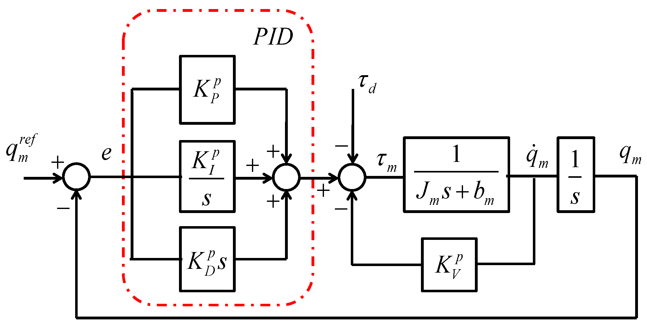
In this section, the proposed method is explained for both parallel and serial realizations of PID controllers with velocity feed-back. The derivation of the proposal is given in the next section. The serial realization of PID controller is designed by using PD and PI controllers in series. Block diagrams of the proposed robust PID control systems with velocity feed-back are shown in
Figure 1 and
Figure 2.
Figure 1.
Block diagram of the proposed PID control system with parallel realization.
Figure 1.
Block diagram of the proposed PID control system with parallel realization.
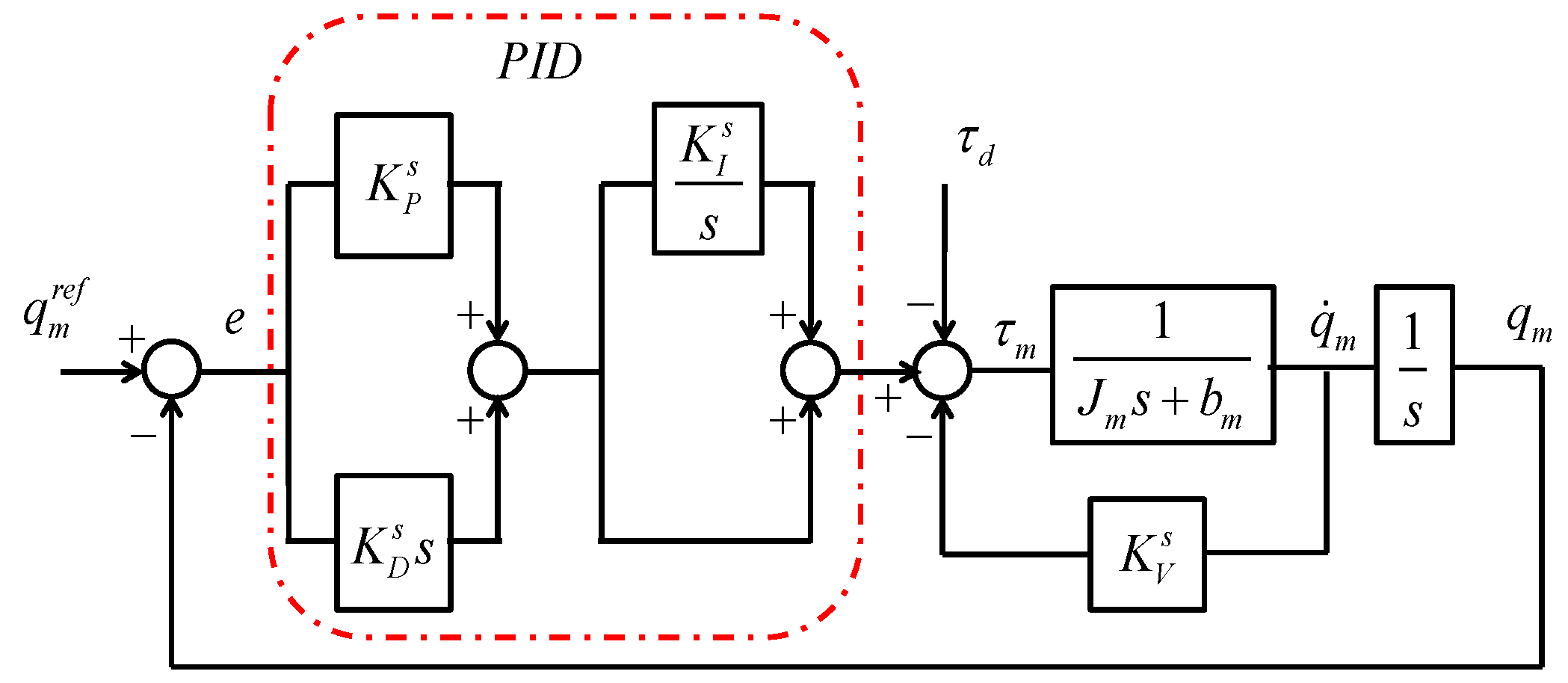
Figure 2.
Block diagram of the proposed PID control system with serial realization.
Figure 2.
Block diagram of the proposed PID control system with serial realization.
In these figures, and the following tuning processes, the definitions given below apply:
| Position of motor; |
| Velocity of motor; |
| Reference of motor position; |
| Position error; |
| Inertia of motor; |
| Nominal inertia of motor; |
| Viscous friction coefficient; |
| Nominal viscous friction coefficient; |
| Proportional control gains; |
| Integral control gains; |
| Derivative control gains; |
| Velocity feed-back gains; |
| Motor torque; |
| Disturbance; |
| Desired proportional control gain; |
| Desired derivative control gain; |
| Natural frequency; |
| Damping coefficient; |
| Robustness variable; |
2.1. Tuning of PID Controller with Parallel Realization
Firstly, let us assume that a servo system is linear and not influenced by disturbances such as friction and external load. Let us also assume that the linear servo system is controlled by using a PD controller. Select the nominal inertia as close as possible to the upper limit of the exact inertia. Set the desired proportional and velocity gains according to the desired natural frequency and damping coefficient as follows:
Secondly, tune
, which is a robustness design parameter, by considering that the higher this value, the more the robustness of servo system improves,
i.e., suppression of external disturbances and plant uncertainties improves as
is increased. Set the parameters of the proposed PID controller by using the following relations.
To improve the robustness, increase
while updating the proposed PID controller gains by using Equation (2) until the system starts to be influenced by practical constraints.
2.2. Tuning of PID Controller with Serial Realization
In the serial realization of the robust PID controller, the desired performance controller is similarly designed by using Equation (1).
It should be noted that the nominal inertia should be selected as close as possible to the exact inertia in order to improve the stability and suppress noise. Further details are given in
Section 4. The robustness of the servo system is adjusted by designing the PID controller as follows:
The robustness can be similarly improved by increasing
; however, it should be kept in mind that it is limited in practice.
A practical high performance robust motion control system can be designed by using the proposed PID controller. The robustness can be directly adjusted by changing the robustness variable
, i.e., as it is increased the robustness improves. However, practical constraints, such as noise and sampling time, limit the robustness of the proposed controller. Since the practical constraints depend on the plant, e.g., noise of encoder, different values of
can be used for different plants. Authors recommend that
should be increased as long as the motion control system is not influenced by the practical constraints.
3. Derivation of the Proposed PID Tuning Method
Disturbance Observer (DOb), which was proposed by K. Ohnishi, is a robust control tool that is widely used in motion control systems and industrial applications due to its simplicity and efficiency [
16,
17,
18]. In a DOb-based robust control system, robustness and performance goals are independently achieved in inner and outer loops. As the bandwidth of DOb is increased, not only external disturbances are suppressed but also the robust stability and performance of the motion control system are improved [
19,
20].
In this section, it is shown that if a PID controller is designed by using the proposed controller gains, which are given in the previous section, then DOb-based robust motion control system is achieved. Hence, a high performance robust motion control system is designed by using conventional PID controllers.
The block diagram of a DOb-based robust motion control system is shown in
Figure 3.
Figure 3.
Block diagram of a DOb-based robust position control system.
Figure 3.
Block diagram of a DOb-based robust position control system.
These additional definitions apply in this figure;
| Bandwidth of DOb; |
| Total disturbance including external disturbance and parameter variations; |
| Estimation of ; |
| Desired motor torque; |
The dynamic equations of a DOb-based robust motion control system are directly derived from
Figure 3 as follows:
The estimated disturbance is equal to [
19]
Equation (7) can be directly derived by substituting Equations (4) and (5) into Equation (6) as follows:
The estimated disturbance can be easily derived from Equation (7) by using:
The motor torque
can be derived by using Equations (5) and (8) as follows:
If the desired motor torque
is defined in terms of position control error and outer loop controller and substitute into Equation (9), then Equation (10) is derived as follows:
Let us define the parameters of the outer loop controller as the desired control parameters,
i.e.,
and
, by using Equation (1) and the bandwidth of DOb
as the robustness variable
. Equation (10) can be re-written by using the new definitions as follows:
The control signal of the DOb-based robust motion control system is same as the control signal of the PID controller with serial realization, which is tuned according to the tuning method that is proposed in the previous section, and equals to the following equation,
If Equation (11) is expanded, then the control signal can also be expressed as follows:
Equation (13) is same as the control signal of the PID controller with parallel realization, which is tuned according to the tuning method that is proposed in the previous section, and equals to the following equation:
5. Experiments
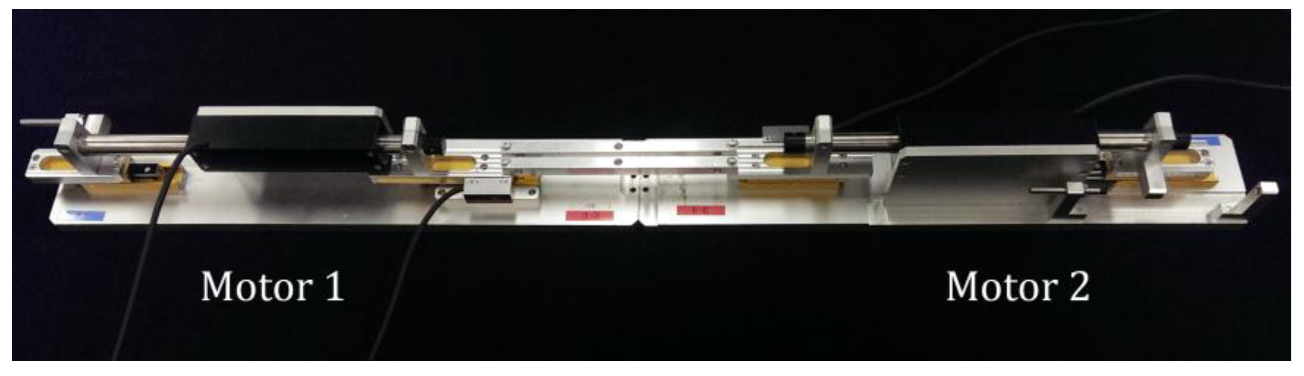
The experiments were conducted by using two linear motors which are shown in
Figure 6. Motor 1 was used for the position control experiment; and Motor 2 was used to apply external sinusoidal disturbance on Motor 1. In the experimental setup, the linear motors are direct drive, and the friction is negligible except the static one. The specifications of the experimental setup are given in
Table 1.
Figure 6.
Experimental Setup.
Figure 6.
Experimental Setup.
Table 1.
Experimental setup specifications.
Table 1.
Experimental setup specifications.
| Parameters | Descriptions | Values |
|---|
| Sampling period | |
| Nominal motor inertia | kg |
| Desired proportional gain | |
| Desired derivative gain | |
| Cut-off frequency of the velocity measurement | |
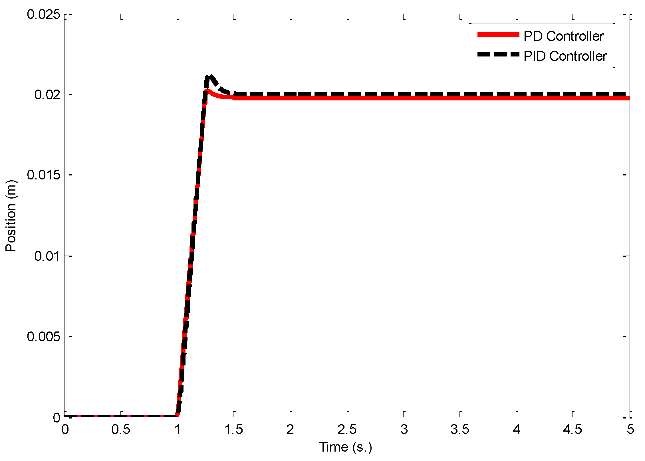
The first experiment is performed without applying the external sinusoidal disturbance that is generated by the Motor 2. A ramp reference input, which increases to 0.02 m from 0 m in 0.25 s, is applied at 1 s. Firstly, a PD controller is designed by only considering nominal servo system model to achieve performance goal.
Figure 7 shows the position control responses of the motion control system when PD and the proposed robust PID controllers are used. The red curve shows that a good performance can be achieved by using the PD controller, which can be considered as the desired controller in our design procedure, when the disturbances are negligible in the experimental setup. The position control response of the proposed robust PID controller is shown by using dashed-black curve when the robustness variable is 500. The performances of PD and PID controllers are quite similar, and the overshoot can be eliminated by increasing the robustness variable.
Figure 7.
Position control responses when PD and the proposed PID controllers are used, and there is no external disturbance.
Figure 7.
Position control responses when PD and the proposed PID controllers are used, and there is no external disturbance.
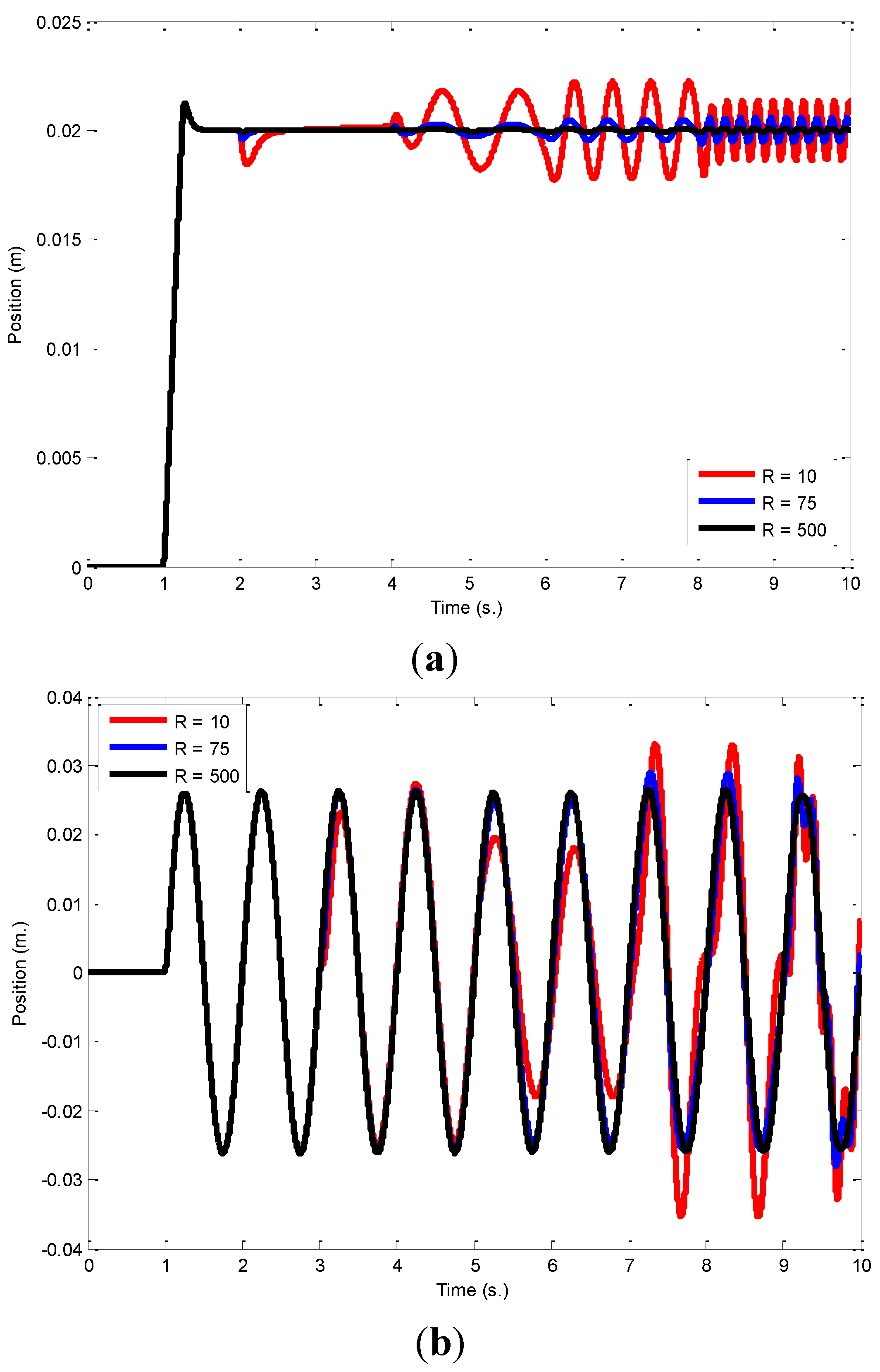
In the second experiment, external sinusoidal disturbance, which is generated by the Motor 2, is applied to the motion control system. The performance of trajectory tracking is evaluated by applying a ramp input and a sinusoidal input, which has 1 Hz frequency, at 1 s. The disturbance is started to be applied at 2 s when the ramp reference input is used and at 3 s when the sinusoidal reference input is used. The frequency of the external disturbance is increased every two seconds by using 0.1 Hz, 1 Hz, 2 Hz and 5 Hz. The position control responses of the proposed PID control system are shown in
Figure 8. As can be directly seen from the figure, the robustness of the proposed PID control system can be simply improved by increasing the robustness variable
R, and a high performance robust motion control system can be easily designed by using the proposed PID controller.
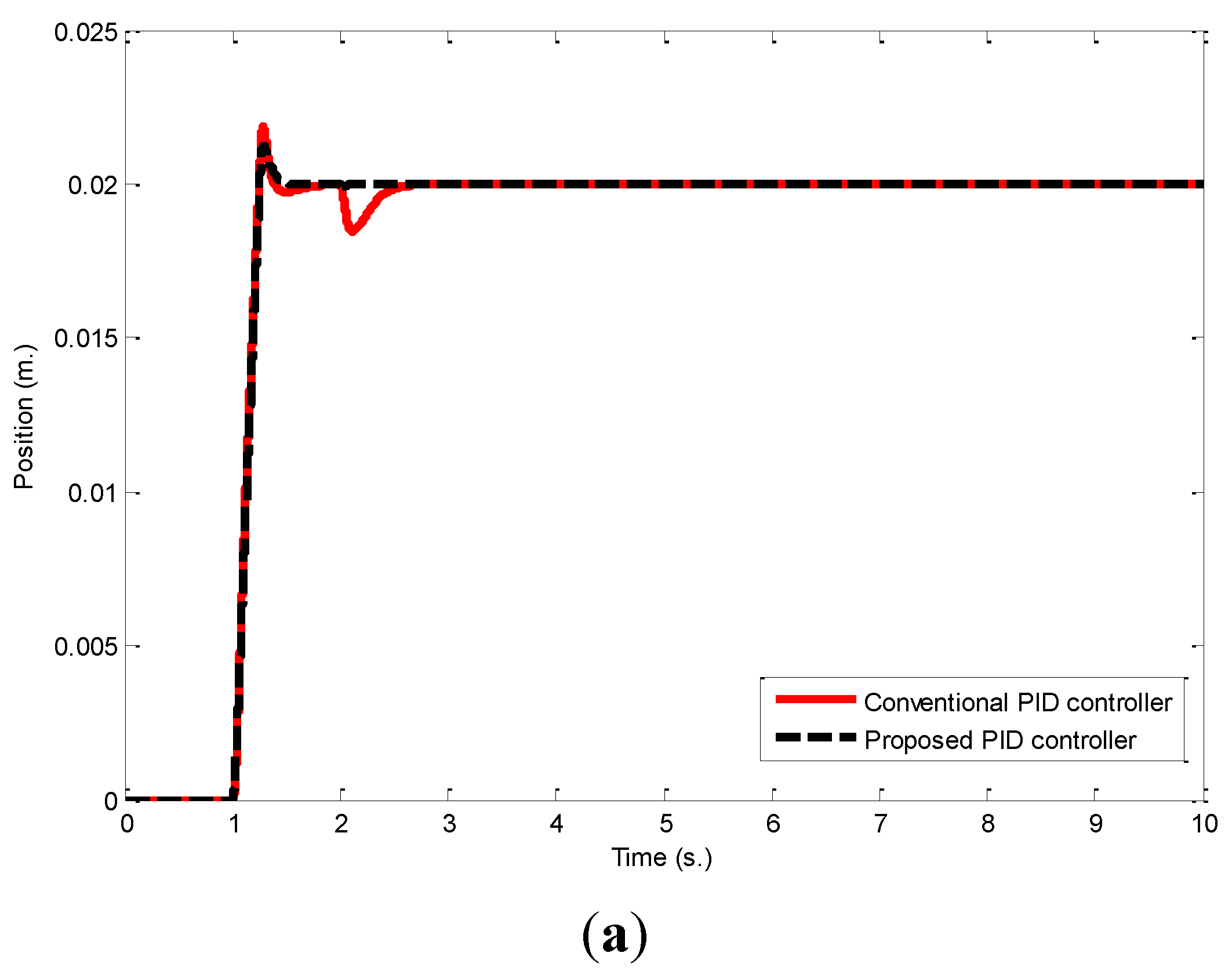
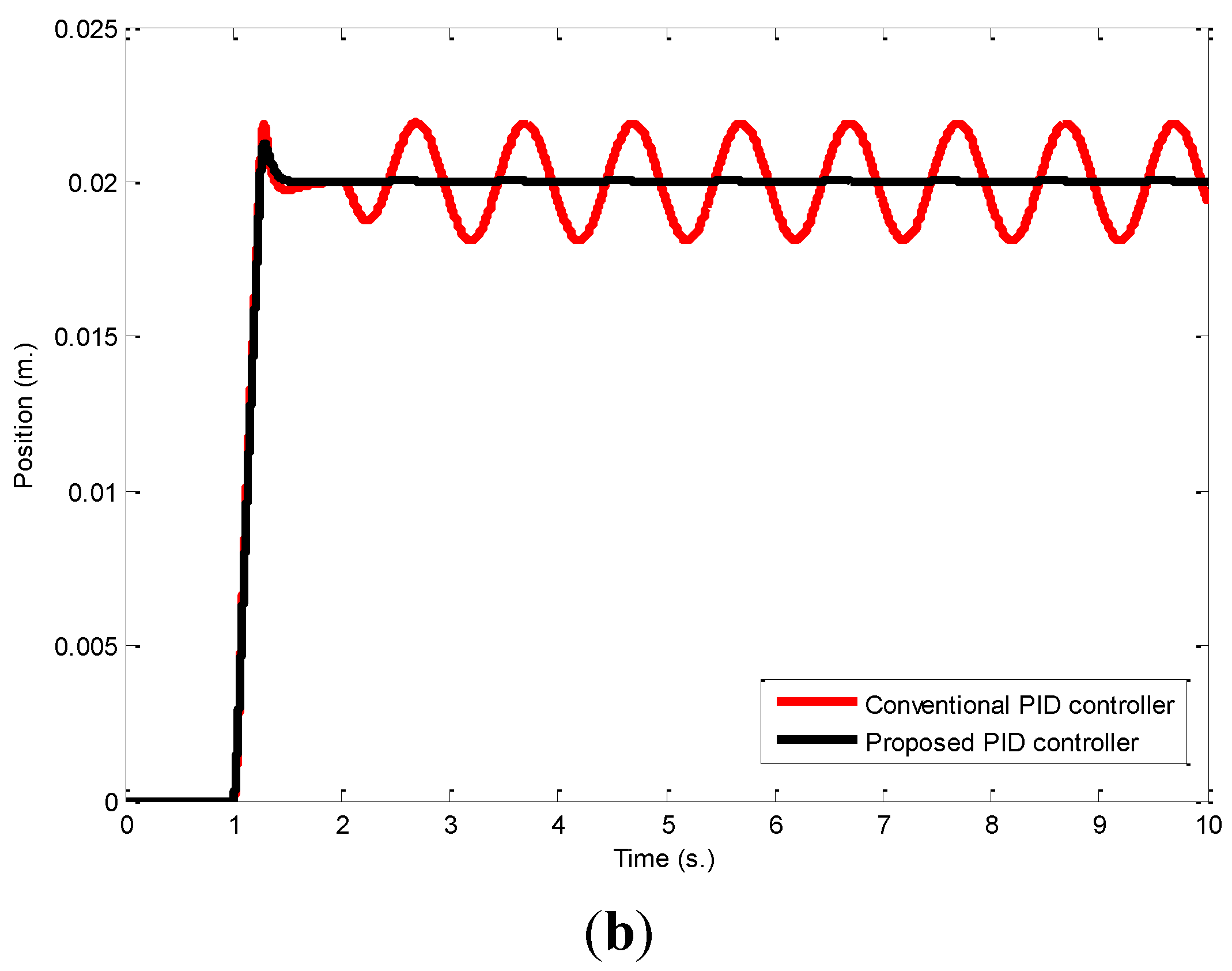
Finally, the proposed controller is compared to a conventional PID controller which is designed by using pole placement method.
Figure 9 shows the position control results when the proposed and conventional PID controllers are used. A ramp reference input is applied at 1 s and constant and variable disturbances are applied at 2 s. As shown in
Figure 9a, both controllers can suppress the constant disturbance thanks to the integral control. However,
Figure 9b clearly shows that the performance of the position control system significantly deteriorates by the variable disturbance when conventional PID controller is used. It clearly shows the superiority of the proposed PID tuning method over the conventional design one.
Figure 8.
Position control responses when the proposed PID controller is used with different values of robustness design parameter R for ramp and sinusoidal reference inputs. (a) Ramp reference input; (b) Sinusoidal reference input.
Figure 8.
Position control responses when the proposed PID controller is used with different values of robustness design parameter R for ramp and sinusoidal reference inputs. (a) Ramp reference input; (b) Sinusoidal reference input.
Figure 9.
Position control responses when the proposed and conventional PID controllers are used for constant and sinusoidal disturbances and ramp reference input. (a) Constant disturbance is applied at 2 s; (b) Sinusoidal disturbance is applied at 2 s.
Figure 9.
Position control responses when the proposed and conventional PID controllers are used for constant and sinusoidal disturbances and ramp reference input. (a) Constant disturbance is applied at 2 s; (b) Sinusoidal disturbance is applied at 2 s.
6. Conclusions
In this paper, a novel robust PID controller with velocity feed-back is proposed for the motion control systems. It is shown that the well-known DOb-based robust position control system can be considered as the PID controller with velocity feed-back when the parameters of the controller are tuned by using the proposed method which is given in section II. The performance and robustness of the motion control system can be independently adjusted: the performance controller, i.e., PD controller, is designed without considering disturbances, and the robustness is improved and disturbances are suppressed by simply increasing the robustness variable R. It is obvious that the proposed method has practical limitations, and the performance and robustness cannot be freely improved. The practical limitations directly depend on the servo system, e.g., noise of velocity measurement and sampling rate. The authors recommend that the robustness variable R should be increased until the servo system is influenced by practical constraints such as noise.
Another important issue in the design of the robust PID controller is selecting nominal inertia. As the nominal inertia is increased, the stability of the motion control system is improved. However, it cannot be freely increased due to the practical constraints. The authors recommend that the nominal inertia should be chosen close to the upper limit of actual inertia to improve the stability and suppress noise. The proposed PID controller is not very sensitive to inertia variation, so stable controllers can be simply designed in practice.
Although a DOb is a well-known robust control tool in the literature, it is not as wide as PID controllers. The proposed method provides that advanced high performance motion control systems can be designed by using conventional PID controllers. The main advantages of the proposed method are the simplicity and efficiency in practice. It can be easily implemented by following the steps, which are given in
Section 2 without requiring the proof, which is given in
Section 3. Therefore, the proposed method has a high impact, not only in academia but also in industry.


