1. Introduction
The last decade has seen the transformation of addive manufacturing (AM) from a technology used in research centres or laboratories for the development of prototypes to actual production techniques with direct results in terms of the market and business. This transformation is ongoing and many companies are asking in which way to take advantage of these changes to capture new markets and develop new products and processes made possible by this production technology [
1,
2]. On the other hand, additive machine manufacturing producers are pressed to develop new solutions, which would allow the use of materials with ever improving mechanical characteristics, smart materials and with production speed and precision in manufacture at a constantly higher level.
AM is changing the way of manufacturing and designing products [
3] and at the same time obliges us to reconsider the machinery with which to realise this production, which has completely different solution requirements based on the subtractive manufacturing. The need to improve performance in systems based on AM and to develop new technology leads us to reconsider the approach to projecting, designing and manufacturing these machines, the control systems, sensor system and movement strategies [
4]. In fact, automated machine design is based not only on science and technology, but also on the art of integrating devices originally designed for other and differing purposes. For instance, if we consider cameras, communication networks, microcontrollers, operating systems, etc., the industrial version of these objects or even the ones dedicated to automation, are often an evolution of something initially created for other purposes, forcing the designers to adapt existing systems [
5]. Frequently the reason for this is linked to the size of a market.
In this scenario, one of the few exceptions is the computer numerical control (CNC), which obviously was not derived from consumer products and was developed for controlling the tool trajectory in multi-axis machines [
6]. It is therefore not surprising that such controllers are designed and can be programmed according to a relatively rigid approach [
7], which makes almost exclusive reference to machine tools and shows significant limitations when applied to other types of machines [
8], including additive manufacturing systems.
In conclusion, designing a machine for additive manufacturing based on industrial CNC and consolidated solutions currently available for traditional wood and iron working machinery limits the ability to achieve the required performance in order to compete in this new market. To overcome this situation, a mechatronic approach to the design of AM machine is necessary to consider all aspects involved in the realisation of these devices.
In this paper, the mechatronic approach to design AM systems is discussed, beginning with some detailed requirements related to motion control, the extrusion system, working volume and machine productivity. The main steps in this design process are described through the development of a machine prototype for an innovative additive manufacturing technology: in fact, a new technology needs a dedicated device to be developed.
The challenge faced in this paper is to develop a completely programmable, flexible and high precision system capable of following the requirements necessary for the new technology and not on the development of a new technology for 3D printing. The machine designed should be considered as an ongoing laboratory and not only as a commercial 3D printer. In fact, to develop the main aspect involved with our new AM technology, such as the powder mixture to be used or the recipe for the sintering procedure, several tests are required and the results achieved must be analysed in relation to the trajectories and motion curves used, temperature, extrusion strategy and the like.
2. MIM Extrusion Based AM Technology Overview
Our prosed new AM technology is based on a MIM extrusion system with the object being the production of high quality metal and ceramic parts. This capacity is one of the key elements required by the manufacturing sector nowadays and can be achieved through technologies such as electron beam melting (EBM) [
9] and selective laser melting (SLM) [
10]. Unfortunately, both of these are required to operate in a tightly controlled atmosphere of inert gas or under vacuum and moreover involve cost and design complexities that create difficulties in their adoption on a large scale. A flexible and simpler possible alternative is being developed at the Department of Mechanics of the Milan Polytechnic, reference [
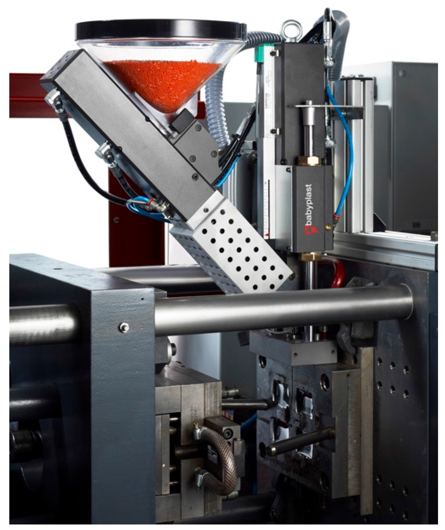
11], based on the design and realisation of a 3D printing solution through the use of a metal injection moulding (MIM) extruder (
Figure 1).
Metal injection moulding is a technique in which a feedstock composed of metal powder mixed with a binder (usually a polymer) is extruded in order to build complex parts in a mould. Once this mixture has solidified, a second phase is required, called de-binding. In this phase the binder is removed, leaving a piece of metal or ceramic matrix that must be sintered.
The additive manufacturing system based on the MIM technology uses the above mentioned extrusor to deposit a thin pasty filament on the workpiece-carrying table through a procedure similar to that adopted in other extrusion-based techniques like fuse deposition modelling (FDM) [
12]. The green part resulting must be de-bound and sintered in order to realized the finish product. Notwithstanding the latter phase, this technique is extremely promising both in terms of printing quality and cost, which are usually very high in SLM or EBM systems.
The essence of our machine is hence based on the extruder shown in the picture: there is a hopper where the feedstock is loaded, after which the material is injected by a piston into a chamber to plasticize it and a second piston extrudes the material through the nozzle. The above design is directly inherited from a commercial solution produced by the company Babyplast® and modified substituting the actuation system with an electrical one which improves the precision, efficacy under our operating conditions as well as a complete control of the flow of material. The extruder also has three resistors with differing powers, 150 W, 500 W and 1000 W whose function is to heat respectively the nozzle, central chamber and plasticizer. Four thermocouples are used to measure the temperature of the system and control it. The functions of the extruder must be completely integrated within the main control system of the 3D printer so as to respect the fundamental technological parameters of the process.
Applications and Potential of MIM Printing Technique
To highlight the potential and possible applications of this technology, we need to give a description of the material that can be used. For the sake of clarity, we are at the initial stages of the development of this new technology and we have only tested Zirconia (ZrO: 94.5%) and some types of steel. At this stage, we are in the process of developing the technology and testing the extrusion strategy and sintering recipe.
The mixture of metal or ceramic and feedstock has been custom made using an industrial binder, Embemould®, made up of three polymers. The binder can be heated up to C but we are testing at a lower temperature, C, to reduce segregation. The extruder can reach temperatures of up to C and is capable of melting any kind of binder.
One of the metal powders used is a 316 L steel with an average grain size of 10 m and mixed with the binder at a mass percentage. The use of this system is obviously not limited only to this material but can be used for instance with copper or any kind of material that can be sintered. Furthermore, this system can be used to print polymeric material including for example some short fibers with the function of a reinforced structure.
With the objective of increasing the number of extruder systems and adding two rotational degrees of freedom of the workpiece-carrying table, this 3D printer could print multi material pieces using free form depositions or curved layering strategies. In fact, having the extrusor system fixed to the ground the orientation of the workpiece-carrying table allows one to compensate gravity.
Several studies have being conducted in these fields; for instance, Goh et al. [
13] show a successful use of an FDM technique for the production of a component with electrical parts embedded. The printing of different materials and free form depositions are involved in this process. Li et al. [
14] studied in detail three different extrusion systems in order to reach a good accuracy and adequate flow rate in the deposition of ceramic pastes. The authors demonstrated the importance of a model of the material extruded, in particular how important it is to know the viscosity in order to obtain a required final density of the sintered parts. Vaezi et al. [
15] review the use of AM techniques for multi material printing purposes (MMAM) based on the material extrusion and the use of a bed of powder. According to the latter research, those based on material extrusion are very promising in the production of ceramic parts, bioceramic scaffolds, biological tissues and even functional parts such as integrated sensors, actuators and control electronics. On the other hand, AM processes based on beds of powder, such as SLM or EBM, are suitable for the production of functional MMAM parts for automotive, medical and aerospace applications. Another interesting development for our technology is the integration of a traditional milling process after the piece has been realized. This idea was developed by Keating et al. [
16]. In particular, they show the advantages of using a milling machine integrated into an FDM printer in order to produce complex parts in accordance with the idea of hybrid manufacturing. The applications and studies set out above are adaptable and can be profitably applied to the machine described in this paper.
3. Requirements
Traditionally, an integrated approach to mechatronics design is aimed at optimizing a design solution through modeling requirements and subsystems so as to asses the most suitable combination of electronics, mechanics and software elements. A typical design sequence, such as that described in [
17], can be regarded as a four-step procedure: analysing the requirements necessary to obtain a sufficient understanding of the problem; creating multiple project concepts that meet such requirements; assessing potential solutions and choosing the best one; and thereafter defining the detailed design of the solution chosen.
This general scheme is primarily intended to mette the requirements of a project starting from scratch and finding an original synthesis between the various disciplines involved. Instead, the application under consideration is not entirely consistent with this scenario because it specifically aims at the enabling the use in production of machinery currently utilized for prototyping. Therefore, the analysis of the characteristics of the new MIM technology and the principal requirements to adapt the machine to a production environment led to the definition of four basic requirements, which should be regarded as major guidelines in the design of the machine, as set out hereunder:
Minimum machine workspace equal to a cube with a side of 100 mm considering the extrusor to be fixed and the platform with five degrees of freedom;
Three translational DOFs, with the possible future introduction of two additional rotational DOFs;
The possibility of implementing different printing trajectories for study purposes. In particular the possibility of printing with a constant extrusion rate in order to obtain a uniform distribution of the material [
18]; and
Printing speed of up to 100 mm/s, being the maximum expected printing velocity required by this technology.
To optimise reliabily and to standardize the requirements within a production environment, the conceptual solution should be based, as far as possible, on the use of commercial off-the-shelf components and the proven architecture solutions currently adopted in state of the art automated machines, leaving most of the design efforts to the correct balance in performance of all the subsystems.
4. AM Features and Mechatronics-Oriented Techniques
The description of the solution followed can be introduced starting from the fundamentals of AM extrusion-based processes and machinery, which can be seen as the deposition of thin material layers following trajectories calculated by specific CAM software usually indicated as
slicers. These software tools receive as input the 3D design data, often provided as a CAD file in STL format [
19,
20] and generate their output as a text file containing a numerical control programming language which will be interpreted by the machine numerical controller. Although this is the same approach and the same technological standard universally used to define the tool path in traditional machine tools, the adding process is inherently different from cutting operations in several ways: among these, two essential differences are that there is no high force transmission to the machine tool and that the precision required by the end effector movement is strongly sensible to the material deposition process.
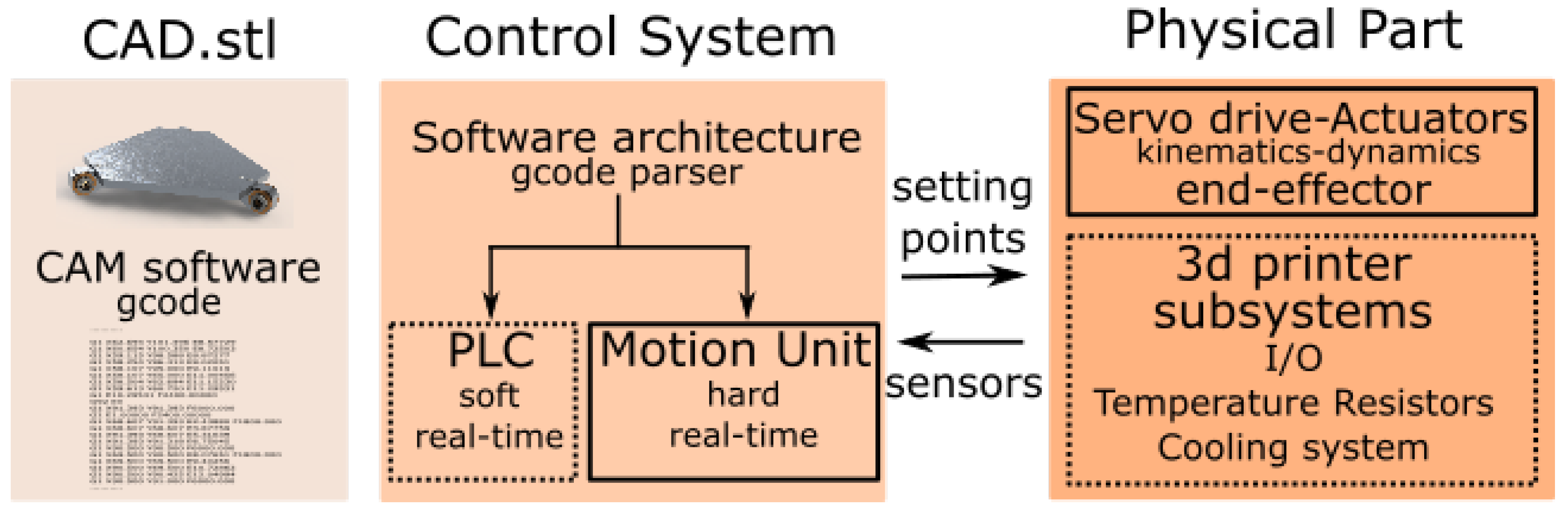
Hence, a high level representation of the machine mechatronic concept could be summarized through the diagram of
Figure 2, which underlines the major division between the control system and the mechanical elements and devices. To proceed in its implementation in an efficient manner, it is necessary to consider a more in depth mechatronics-oriented approach in order to make the development process more integrated with respect to the past. In fact, before, different disciplines were addressed through a sequential development starting from the mechanical one, where design decisions were made independently and the control team was not involved until the first prototype was built and became ready for programming.
Nowadays, mechatronics-oriented design tools improve and assist the development process by simulating the interaction between mechanical and electrical subsystems, making it possible to work in parallel and cooperate on design, prototyping, and deployment. In most structured environments, this process is carried out through the following steps:
Including the disciplines involved in formal design reviews;
Formally documenting cross-disciplinary design open points and provide notification of possible issues arising from changes in inter-dependant subsystems;
Setting design performance metrics for all engineering disciplines and formally collect, manage, and track design requirements throughout the development process; and
Using assessment techniques, including those based on simulation, to detect weaknesses or criticalities—usually, the same simulation tools can also provide support to set the optimal trade-offs.
In the course of the design process, a mechatronics project has some typical key decisions to be taken and key dependencies to be considered starting from the earliest phases. The identification of such relevant issues can result in frequent design reviews conducted by the entire cross-discipline team. Some typical examples of these can be listed as follows:
Architectural choices: Motion system type; Motor type; PAC, PLC, SBC or custom;
Sizing: Transmission sizing; motor sizing;
Design choices: Sensor placement; Mechanical stiffness requirements;
Devices and components: Actuator and sensor selection; Motion controller and drive; I/O module selection; and
Coding: Logic, timing and sequencing; Motion trajectory design;
This list should not be regarded as a comprehensive check-list but as a set of elements which illustrate the kind of inescapable cross-dependencies to be considered and solved. A typical project is expected to include these main aspects:
Decide which type of motion control conceptual design should be applied. Such a fundamental architecture decision will drive almost all the other machine aspects. Common alternatives, among others, could be e.g., linear Cartesian gantries, SCARA robots, rotary indexing tables, and conveyers.
Select the mechanical transmission components and motors to obtain the required precision and throughput, which can be obtained by a proper sizing of the motor torque and velocity. Their calculation can be done on the basis of the requirements needed to execute the motion trajectories and to deal with the inertia of the mechanical load.
Design the motion trajectory in detail. While the approximated shape of the tool motion can provide starting indications on the machine characteristics, only a detailed description of its motion allows the calculation of how the part accelerates along the path. Consequently, one can calculates the inertia forces which in most cases represent the greater part of the resistant torque and consequently greatly affect the motor choice. Especially if the motor is mounted in a movable part and therefore its mass influences the inertial load, it is probably necessary to proceed iteratively to reach the correct sizing.
Define the control logic and the cycle time of the machine. Their modifications have consequences on the dead time, and operating duty cycle which can require the resizing of the motors.
5. Detailed Design
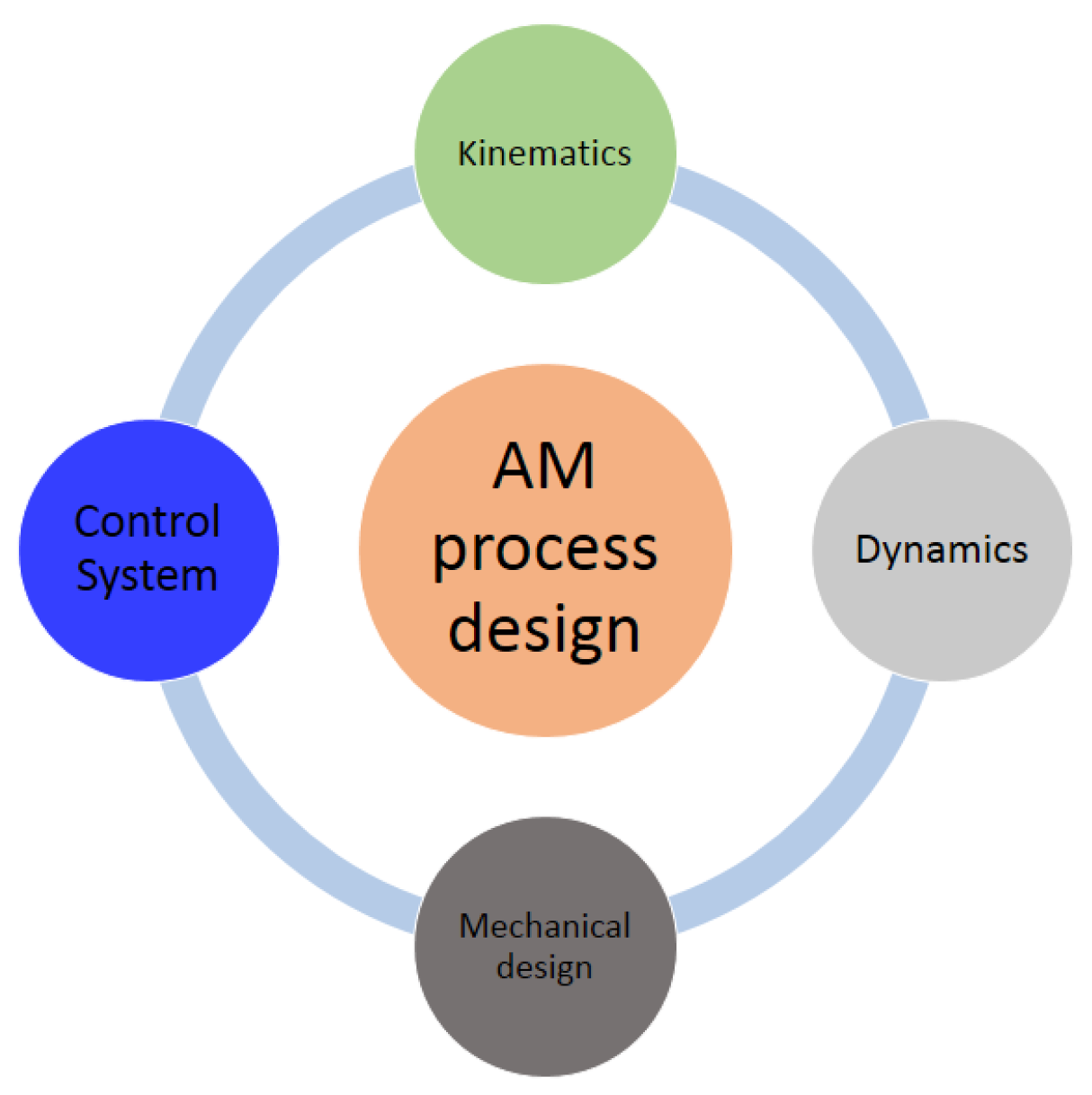
The overall design of the machine is carried out taking into account the main characteristics of the technology used with respect to the design specifications. The design process is explained starting from the choice of the kinematic architecture with an optimization of its geometrical parameters through the use of a genetic algorithm; a dynamic model is developed and this is used to size the actuators of the system and furthermore how it can be used for the evaluation of the printing process feasibility is explained. The mechanical design of the entire machine originates from the results of the dynamical study, whereas the control system is described by outlining how this manufacturing process has been specifically designed. The design cycle is summarized in
Figure 3.
5.1. Kinematic Study
The kinematic study begins with the choice of the machine general architecture meaning topology and number of degrees of freedom. The required workspace, as set out in
Section 3, is described as a cube with a side of 100 mm within which the tools can be moved with at least 3 translational DOFs.
Due to the considerable weight (about 25 kg) and size of the extrusion group, it is preferable to keep it fixed and apply all the required DOFs to a movable platform of the machine. To guarantee a good dynamic response and a high positioning accuracy, the chosen robotic architecture consists in a linear delta robot capable of providing three translational DOFs to the platform shown in the
Figure 4.
This choice permits us to take advantage of the guides in order to create the framework for the machine. Moreover, the chosen kinematic structure allows one to obtain the constant kinematic properties by varying the platform vertical position, which, in case of a 3D printing process, is equivalent of maintaining the same kinematic behaviour on each printed layer.
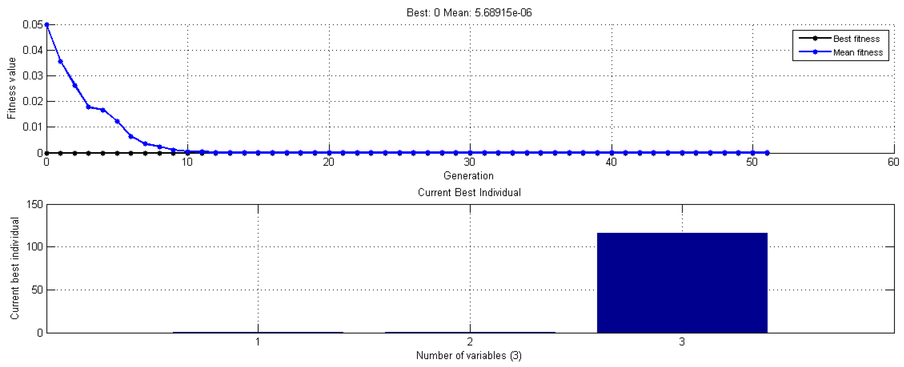
A kinematic optimization has been carried out to synthesize the geometrical parameters of the robot. The optimisation uses a genetic algorithm approach [
21] based on the inverse kinematics of the robot as referred to in Equation (
1). The position of the sliders is described by means of the variables
that are expressed in function of the length of the legs
l and the parameters
being the radial distance of the links on the movable platform.
Figure 4 shows the main parameters involved in the kinematic definition of the robot. The optimization method is developed by the use of the Matlab
® function
ga [
22].
Figure 5 shows the trend of the dimensional convergence of the final working space of the PKM during the ga optimisation process.
To reduce the staircase effect, a typical problem that afflicts 3D printing processes based on the layering approach, a two rotational DOFs platform has been taken into account during the design and optimisation phase. For this reason, the workspace should be greater than the one set out above. In fact, it is necessary to increase the translation capacity of the working platform in order to compensate the effects due to the rotational degree of freedoms [
23].
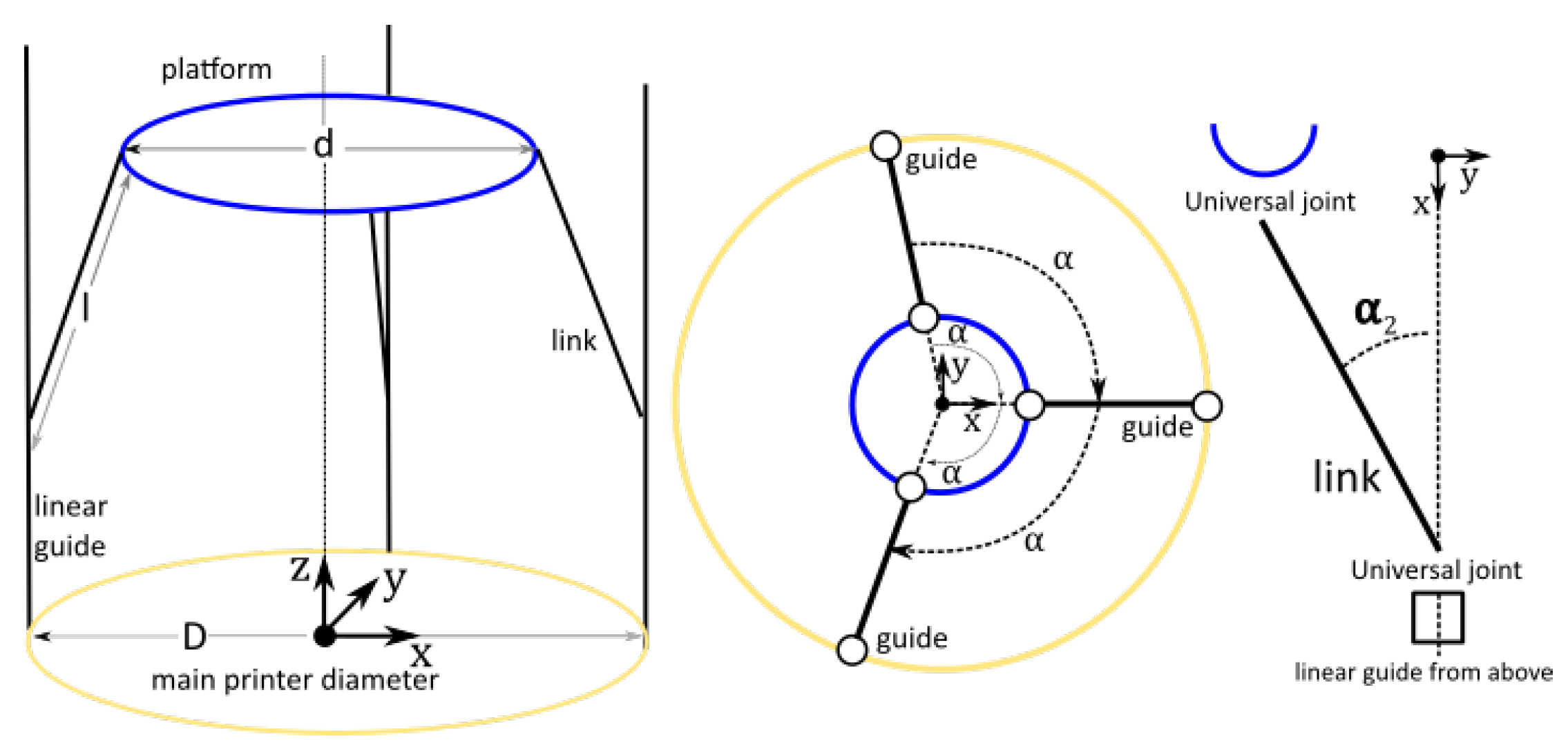
In
Table 1 the geometrical parameters used to describe the kinematics of the system and the related range values used within the genetic algorithm are listed. These parameters are:
d the diameter of the movable platform,
l the length of the linear delta legs,
D the diameter representing the distance of the linear guides from the centre of the machine, and
the angular position of the guides with respect one of them assumed as reference (
Figure 4).
The kinematic study is divided into two phases: the first one based on a dimensionless study in order to understand the influence of each parameter on the robot workspace; and the second one based on a dimensional study where the exact values of these parameters will be defined.
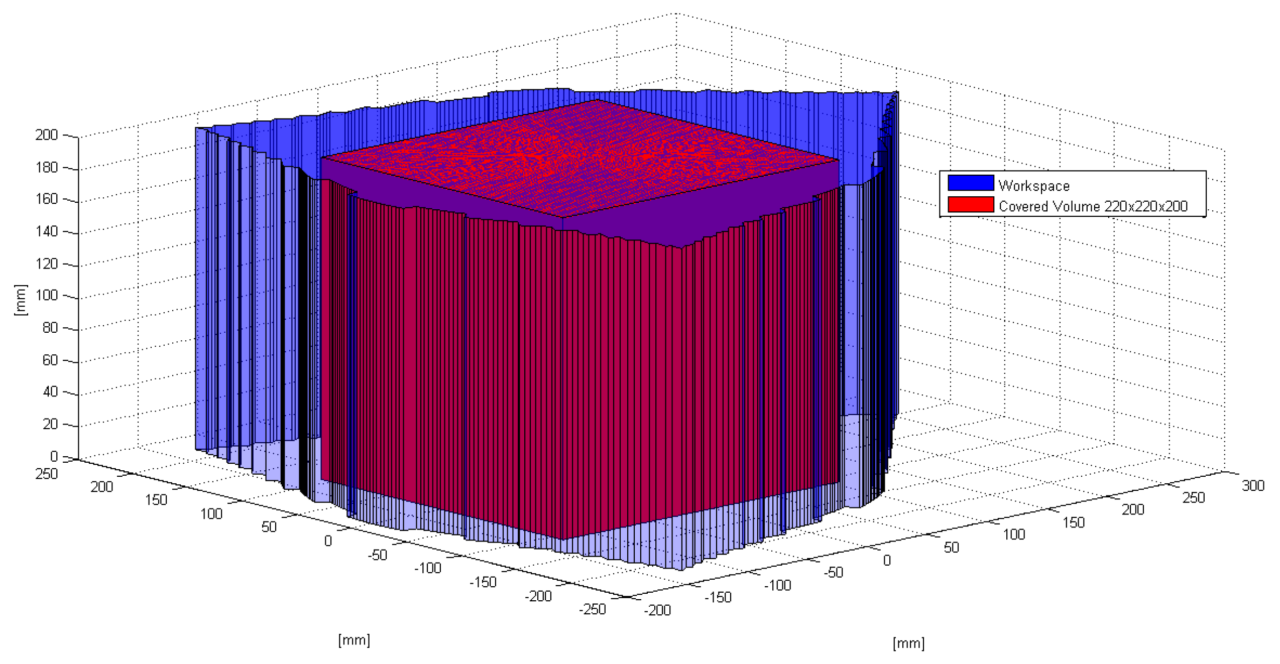
For the dimensionless study, every parameter is divided by D which represents the size of the entire machine. The ga function is used to maximize the area covered by the robot and consequently its workspace. It should be noted that, thanks to the properties of this robotic architecture, the study has been limited to a plane, because along the vertical direction the workspace and the kinematic properties are constant. Whereas for the dimensional optimization the parameter d is set equal to 400 mm which is the size of the required printing plate. In that case the ga function is used to cover a square of side 220 mm in order to cover the entire cubic workspace and to install the two Dofs rotational platform for future applications.
The optimisation process is constrained by means of the following parameters: the force
and velocity
transmission factors and the maximum rotational angle
of the joints (
Figure 4). Force and velocity factors derive from the Jacobian matrix of the robot and they are used to limit the forces that the linear guides must bear. As shown in
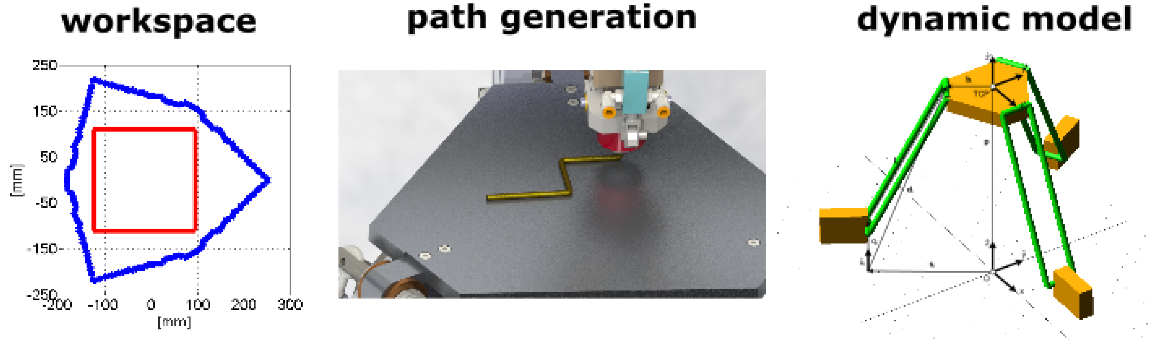
Figure 6, the area, covered by the linear delta platform, includes for each X-Y plane a square of side 220 mm.
5.2. Dynamic Model
To size the actuation system and simulate the printing process, a dynamic model has been developed using the multibody simulation software Adams
®. The extruder is not taken into account in the model because it is fixed to the ground. The model is based on the geometrical parameters derived from the kinematic optimisation and the mass and inertia values obtained by the CAD model developed to realise the device. In
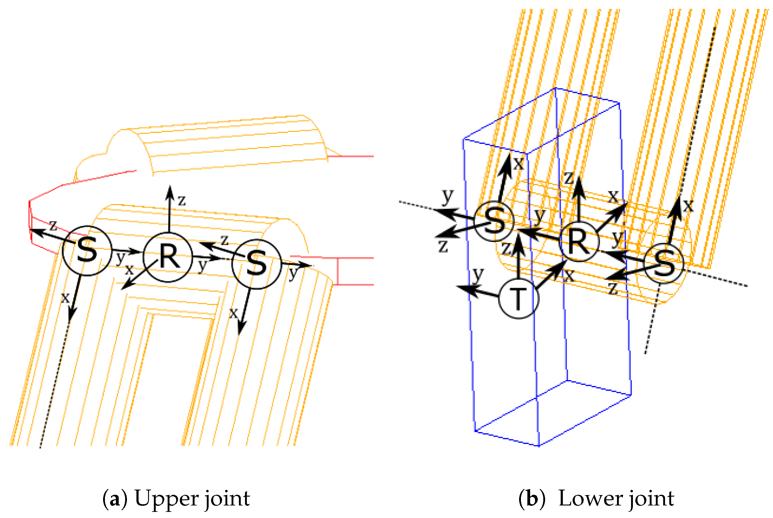
Figure 7 the two most important parts of the model are shown. In fact, the linear delta architecture is made up of three parallelograms that connect the movable platform to the three sliders by means of composite joints.
A slider, which represents the active joint in the model, is represented in
Figure 7b by means of a blue parallelepiped grounded with a translational constraint,
T, free along the
Z direction (vertical movement). The connection between the links and on one hand the moveable platform and on the other hand the slider is realized in the same way: two spherical joints are installed on an axis connected to the slider or the movable platform by means of a central revolute joint.
The reference task used in sizing the actuation system is obtained imposing, in different workspace positions, a sinusoidal movement with amplitude of 150 mm and frequency of 1 Hz along all the three DOFs of the robot. The maximum payload of 8 kg, obtained from the cubic workspace volume of side 100 mm filled with material with density comparable to that of steel, and an extra weight of 8 kg, representing the two rotational dofs platform, are taken into account to calculate the motor torque. Following the method presented in [
24,
25], and exploiting the dynamic model, brushless motors and gearboxes have been chosen and correctly sized; in the
Table 2 the results are shown.
Note that, using the multibody model, it is possible to calculate the force applied to the slider,
, during the movement of the mobile platform and knowing the value of the acceleration of the slider,
, it is easy to calculate the motor torque
using the following equations:
where
and
are, respectively, the diameter of the pull inside the linear guide and the equivalent friction coefficient of the system. The multibody model and the previous equations are useful to size not only the actuation system but also all the components of the machine.
The dynamic model can be used such as a simulation tool capable of studying the feasibility of a 3D printing task before using the machine (
Figure 8). In fact, taking into account a deposition path delimited in a square of side 220 mm, it is possible to calculate accelerations, velocities and the like during the whole process. Then, using the inverse dynamic approach with the multibody model and the equation set out in Equation (
2) the motor torques are easily calculated. Several simulations can be done according to the requirements and using the same path that it will do during the actual printing task: this approach is oriented towards a tailored design for the specific manufacturing process.
5.3. Mechanical Design
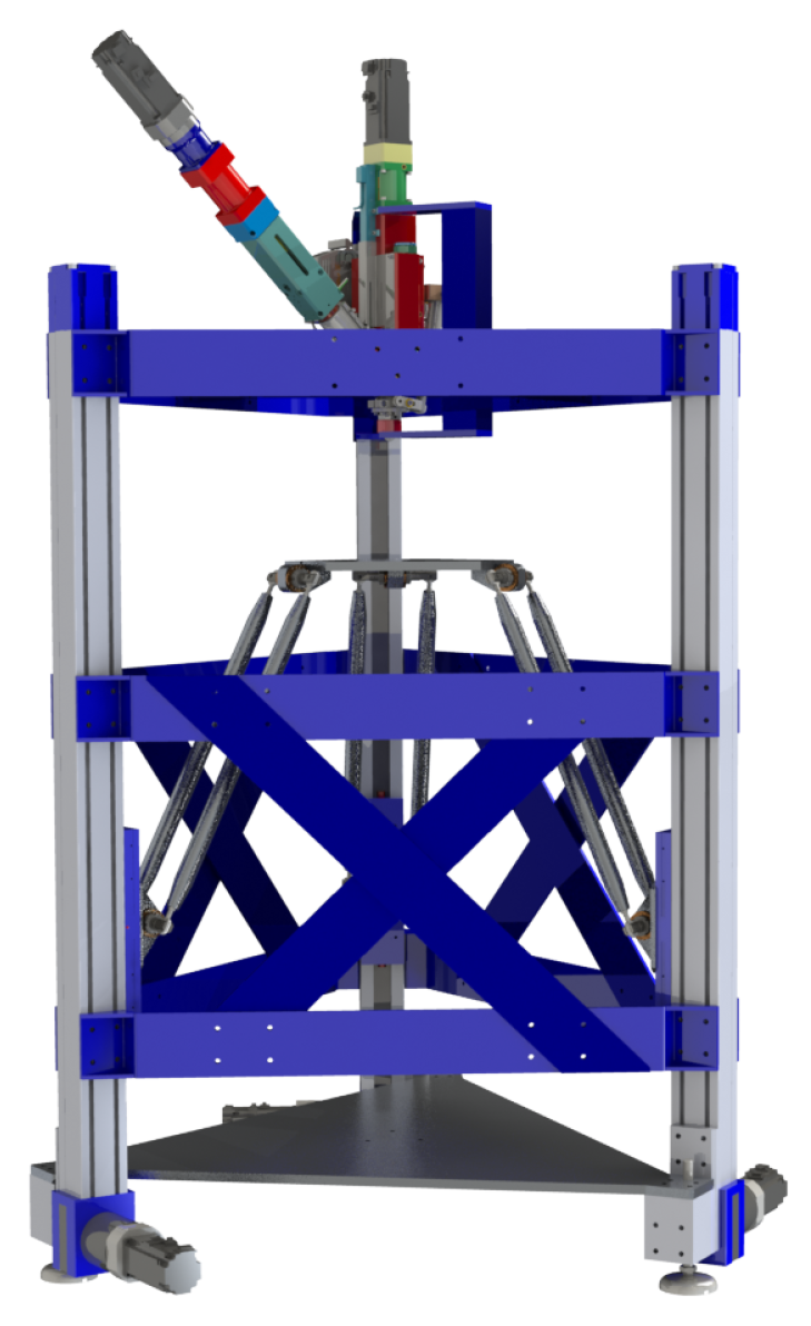
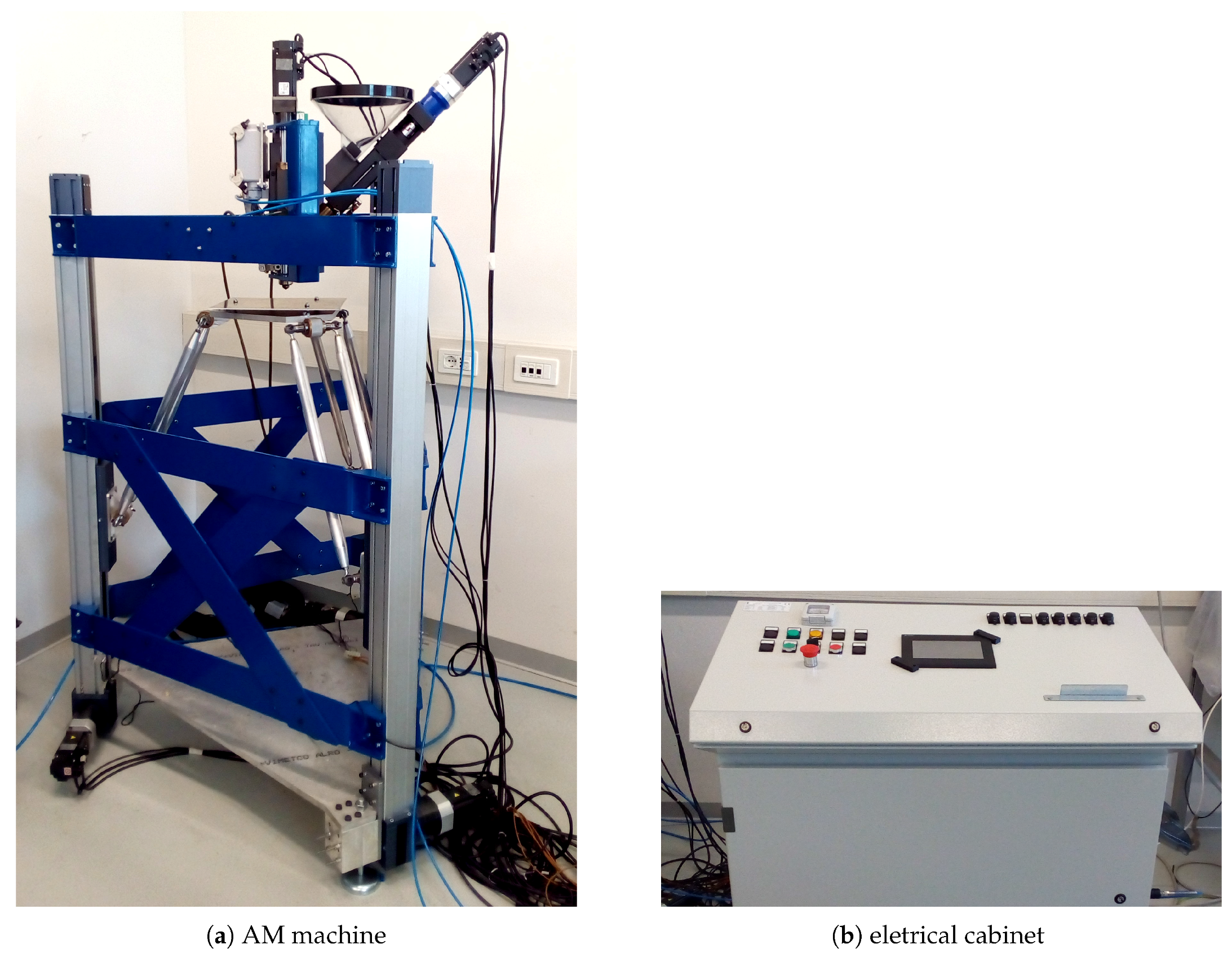
In
Figure 9 is shown a machine rendering as built. The machine is about 2000 mm high, including the extruder, and it is about 1000 mm wide. A mechanical description of the main elements of the printing system is set out thereafter. Please note that the mechanical design of every single item of this machine has been developed by using the multibody model and the dynamic analysis of the system.
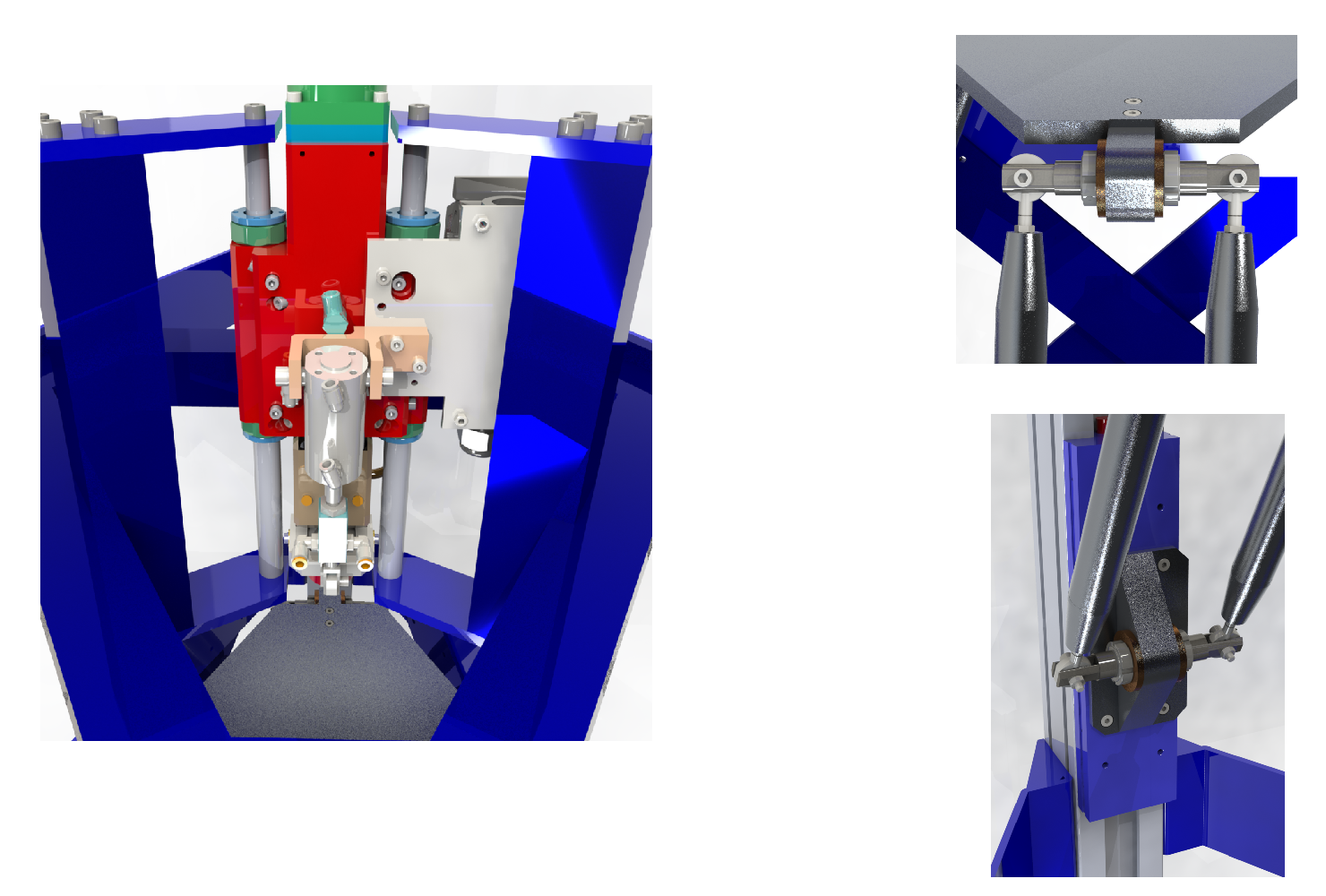
Special attention has been given in the design of the joints shown in
Figure 7; the loads are defined by means of the dynamic analysis and used to size the universal joints, the rotational joint, the prismatic joint (linear guides) and the legs. In particular, the universal joints are realized by the use of a shaft with a central rotational joint and two rod ends placed at the extremity of this shaft in order to add the remaining dofs needed to complete the universal joint configuration and to guarantee the required mobility of the movable platform. Note that the rod end is plugged into a fork realized on the shaft and the possible collisions between the parts has been taken into considerations. This solution allows one to reach a rotation of
around the shaft and
with reference to the homing configuration of the mobile platform as shown in
Figure 4.
The rod ends are chosen from the commercial catalogue of SKF “Spherical plain bearings and rod ends”, the chosen model is “SA 8 E”, these rod ends allow one to realize a complete rotation around the axis and a rotation of around the remaining two. The rod ends have been chosen taking into account the static and dynamic load, respectively kN and kN. These values are very high compared to the loads acting on the rod end but allow us to use a system of belleville springs between the rod end and the shaft in order to preload the joint and reduce the backlash.
The C40 steel shaft has been sized considering the maximum forces and torques evaluated in the most critical sections of the shaft in accordance with the permissible loads of the copper bushings, SKF PBMF 253516 M1G1, which bear it. The most critical sections are the extremities where a fork is realized in order to fix the rod end. Note that the absolute value in terms of stress is very low (maximum stress of 46.6 MPa), compared to the tensile strength of the carbon steel C40 and therefore adeguate to ensure low deformation and consequently, high precision positioning.
The rod ends are linked with aluminium tubes that represent the legs of the linear delta robot. The tubes 30 mm diameter and 3.5 mm thickness are capable of bearing the maximum axial force fo N with very low deformation.
The results obtained from the dynamic simulations are also used to size the linear guides, in particular, the maximum velocity and acceleration (respectively, 5.91 m/s
and 0.943 m/s) and the forces and torques on sliders have been taken into account for this purpose. In the linear guide sizing procedure, the most critical value is the torque around the axis
z,
Figure 4. This torque reaches the maximum value of 38.2 Nm. The choice procedure results in the guide model ELM 80 SP by Rollon, which allows one to reach the maximum linear acceleration on the slider of 50 m/s
, the maximum velocity of 5 m/s and the maximum torque along
z axis of 58 Nm. This guide belongs to the family of the belt driven linear guide.
Figure 10 shows the extruder fixed on the top of the machine by means of a frame made up of welded steel bars. The whole structure of the machine is based on the three belt driven guides that constitute tree pillars linked the one to the other by means of steel plates. At the bottom of the machine, an aluminium plate is placed in order to close the machine and protect cables and electronic devices. This structure has been designed to increase the stiffness and to avoid damaging vibrations during the 3D printing working phases.
5.4. Control System
3D printers usually work with a G-code, generated by a slicing software and executed subsequently by means of three elements: an interpreter, a PLC and an interpolator. These software tools are usually tailored on the CNC machine in order to parse the g-commands, execute sequential control and interpolate the trajectories for the actuators respectively [
26]. For Additive Manufacturing machines, derived from CNC solutions, usually no customisations are made to change the trajectory obtained from the G-code with respect to the additive manufacturing technology used in order to improve the performance.
In the study presented in this paper, a mechatronic approach has been used in order to bend the control system to our technological requirements. In particular, due to the novelty of the AM technology during the early use of this machine, a constant extrusion rate is required in order to perfect the mixture of the feeding material (feedstock based on metal powder and binder) and develop the processes involved in passing from the 3D printed piece to the final one. Moreover, taking into account the novelty of the machine it is necessary to develop a dedicated G code interpreter in order to translate specific G commands in a useful set of information for a dedicated interpolator in order to generate the required motion curves.
For these purposes, open motion control systems (CNC controls) are available on the market such as the so-called Delta Tau [
27] controller by Omron. These devices provide an software architecture capable of implementing any kind of kinematic equation given by the user in order to control multiple axis systems and make available to human interfaces and I/O channels to connect auxiliary devices.
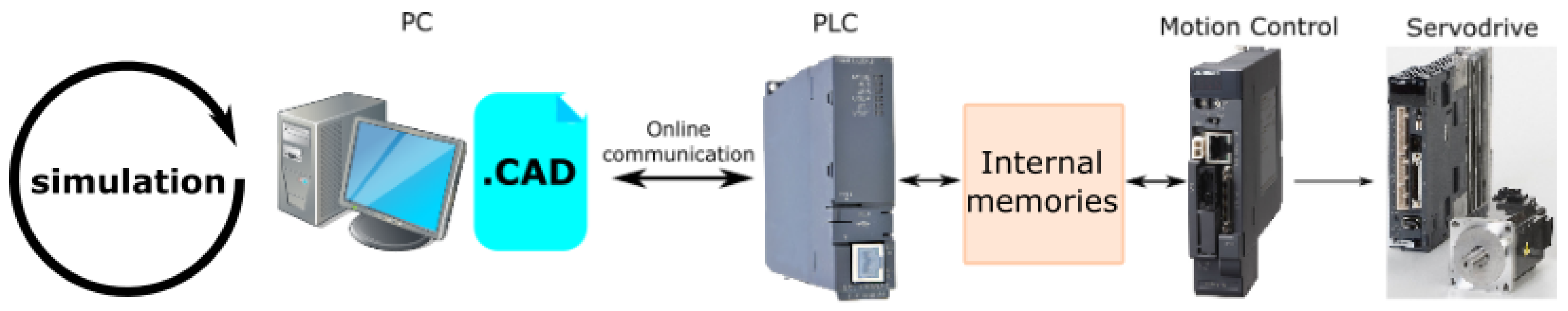
As shown in
Figure 11, a different solution is here adopted based on a modular approach with an industrial PLC for soft real time tasks and a motion control unit for the hard real time control of the actuators. This solution allows one to implement a generic trajectory starting from G-code but with costs generally lower than a CNC controller based solution. To complete the architecture, a personal computer is recommended not only to generate the G-code from the 3D model but also to translate the G commands into specific tasks to be followed by the control system.
For the solution under consideration, a PLC and a motion control unit, mitsubishi model Q03UDVCPU and Q172DSCPU, is used to control the 3D printer.
Figure 12b is represented the control work-flow and the architecture. Note that a personal computer is used to communicate with the PLC via USB or Ethernet cable in order to stablish an online comunication with the machine and to help accomplish the manufacturing process. The PC can override different memory zones of the control system by providing a continuous flow of instructions for the PLC and the motion control unit. This is possible because an additive manufacturing process is usually slow. This solution allows one to exploit a maximum a control system already developed customizing its use for a specific purpose.
Summarizing the whole 3D printing process, the main steps are:
A CAD file of the object to be printed is created.
Using a slicing software a G-code is generated. In the case under analysis every line of the G-code represents the position of the moveable platform.
G-code instructions are extracted and used to generate a customized trajectory according to the required technological aspects. This and the previous two steps are done off-line.
At the beginning of the process, the PC fills the memory of the PLC and that of the motion controller. Thereafter, the printing phase starts. In particular the PC communicate with the motion controller the sequence of the points that must be reached and the systems begins to print.
During the printing phase the PC constantly updates the memory of the motion control in order to have a continuous movement.
During the process, the PLC is also used to do auxiliary tasks such as controlling the extruder temperature and accomplishing other checking tasks.
This process is suitable for the use with low memory space systems, wherein it is impossible to store directly all the points of the trajectory into their memory at the begining of the process. The same happens for the CNC based system but the problem is overcome by executing the G-code lines online through the use of an interpreter and an interpolator. The G-code in fact is a file with a relatively size small which encapsulates all the informations needed for the production process. The proposed structure achieves two goals:
Generic trajectory generation G-code is initially used to extract the basic points for the 3D printing process but the strategy used to move from one point to an other can be changed as required.
Tailored solution The use of a system based on PLC and motion control unit offers high flexibility and highly customized possibility in function to the AM process under use.
With this workflow, it is possible to implement different kinds of trajectories according to the requirements. For example, in this application, to support the requirement of having a constant flow rate extrusion, the trajectories developed to move the platform have been created by means of an algorithm based on the Bézier curves [
28]. Starting from the G-code obtained by the slicer, the proposed path planning allows one to generate the best trajectory for constant flow rate extrusion.
In fact, using Equations (
3) and (
4), it is possible to maintain a constant velocity along the trajectory followed by the platform and equal to the extrusion rate of the extruder. The trajectory is based on the parameter
u, and is obtained through a combination of Bézier curves lines and parabolas where the velocity
is kept constant.
An important input parameter of this algorithm is the variable
that defines the maximum acceptable margin of error between the points obtained from the G-code and the ones used to define the trajectory of the platform.
Figure 13 shows an example of trajectory based on three points: the path starts from the first point and ends at the third; the parameter
sets the distance between the trajectory and the middle point. In a trajectory made up of n-points, the
distance is respected for all the even points of the path, (n-2) points. This parameter defines the accuracy of the process or in other terms the velocity of the extrusion.
6. Printing Workflow
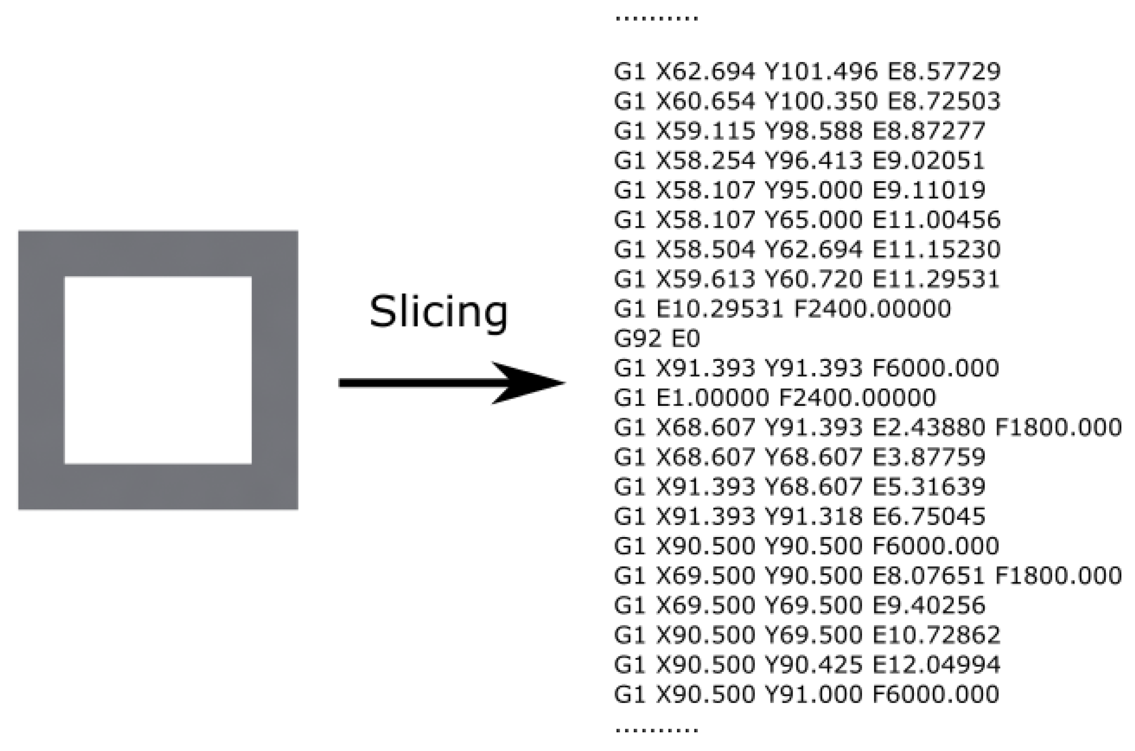
This section describes the complete printing workflow and highlighted how this integrated solution allows one to have the maximum working flexibility. A simple example is used such as test bench: a square with a squared hole is shown in
Figure 14.
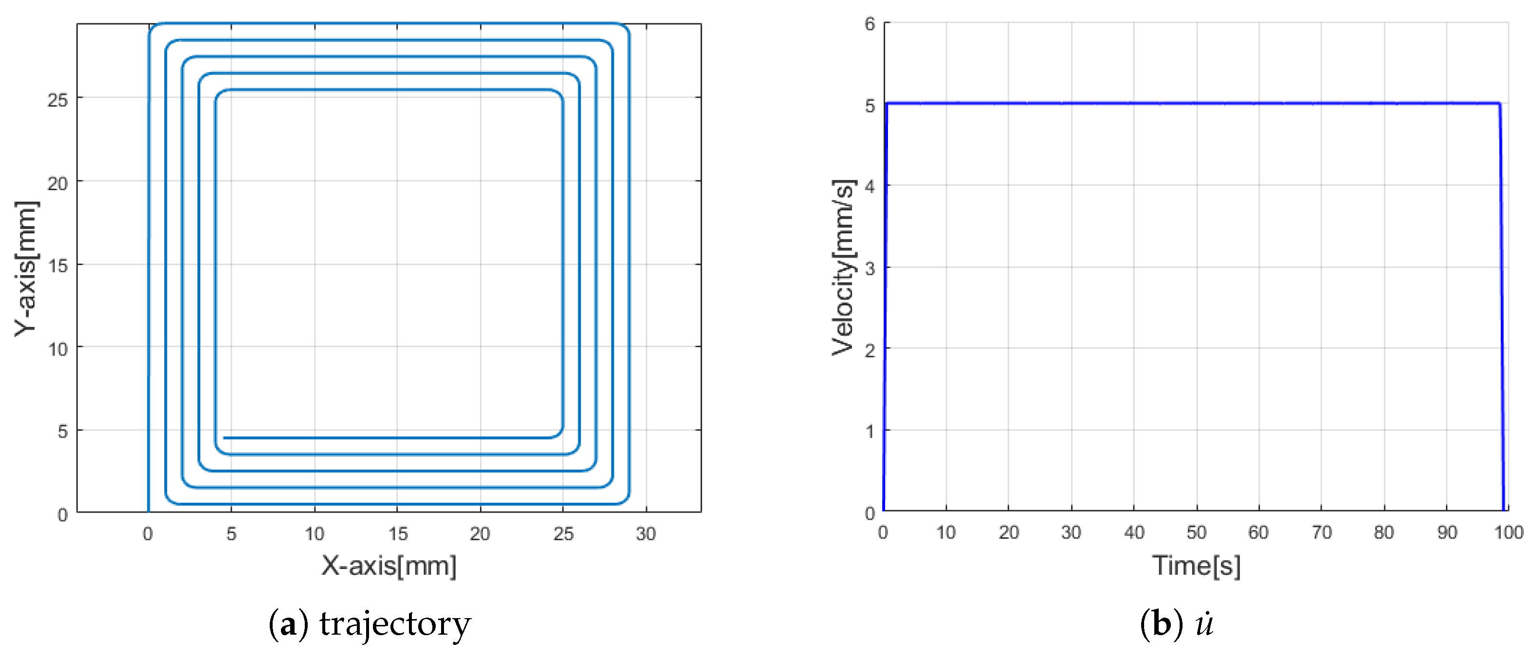
Firstly, the 3D model is exported in a STL format, which is the standard file used for the 3D printing processes, and from which is possible to obtain the G-code by using a slicing software such as the open source slicing software called Slic3r.
The G-code must be interpreted and used to generate the command to supply to the system. For instance, F-commands, E-commands, which define the feedrate of the extrusion head and the amount of filament extruded are not directly usable for the purpose of this machine. Moreover G-commands, such as G1 which defines a movement with a linear interpolation, impose a final path to the platform which are not suitable for this MIM technology, as set out before. Vice versa, from the G-code, it is possible to extract the coordinates
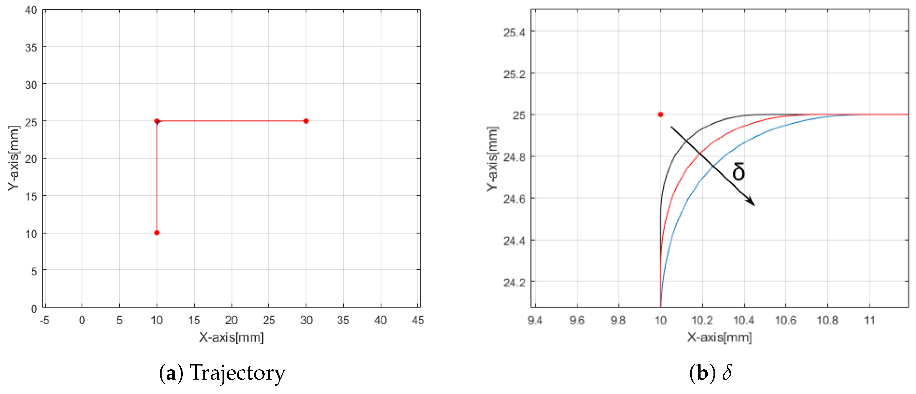
of the points that the platform is supposed to follow. Using these points such as input of the path planning algorithm, the actual trajectory is obtained (
Figure 15a), taking into account as working principle a constant rate extrusion [
28]. Note that for printing a holed square, the values
(
Figure 15b), parametric velocity, and
, which defines the maximum acceptable error, are set respectively equal to 5 mm/s and 1 mm. The value
is kept broad in order to have a smooth profile.
Acting on the positioning precision of the linear delta together with an accurate regulation of the process parameters, such as printing velocity and layer thickness, will allow to change the result of the printing task and improve the results according to the of material used, time execution and the like.
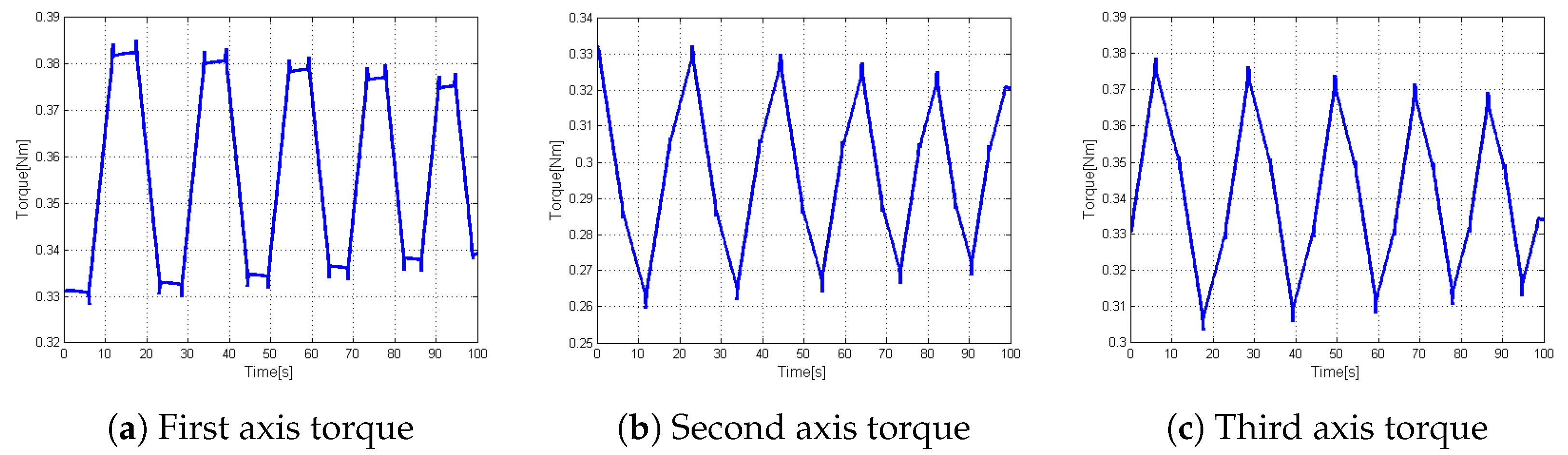
Using this mechatronic approach to define the printing steps and this system architecture, it is also possible to simulate the trajectory planned by means of the multibody model set out above and evaluate displacement, velocity and accelerations of the sliders and consequently forces and torques acting on the actuation systems.
Figure 16 shows the torques obtained from the mutibody model during the whole printing process. In the case under analysis it can be noticed that the required torque is lower than the nominal torque available for each motors,
Table 2. This is related to the very low printing velocity (2.5 mm/s). It is interesting to highlight the effects due to the constant flow rate strategy used to extrude the material on the trend of the motor torque which is characterized by some unavoidable peaks.
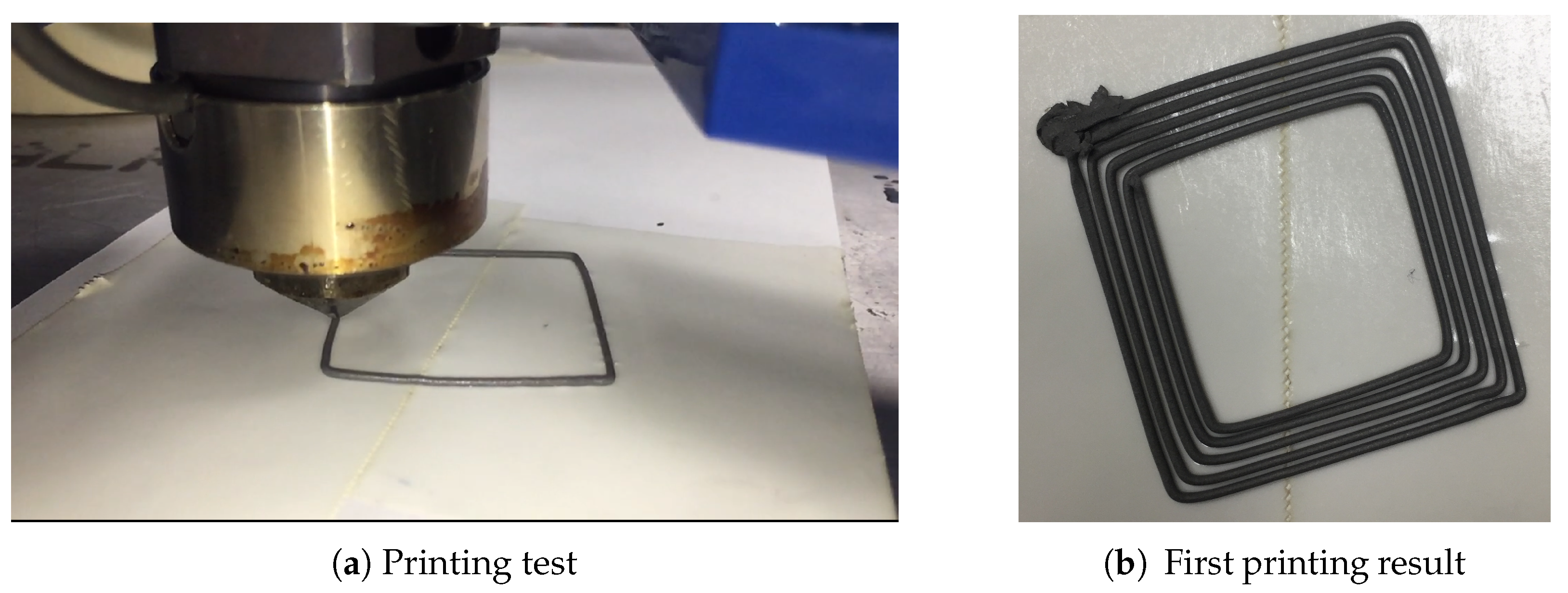
Having checked the process feasibility, it is then possible to proceed with the printing phase. By means of an application developed in C# a communication between the personal computer and the PLC is established exploiting the internal memory of the system in order to control the machine without idle times and to realize the path proposed.
Figure 17 shows the machine and the first task realized. This 3D printer based on an innovative technology is now ready to be used for experimental purposes in accordance with the design parameters. To characterize this new technology and to obtain a good printing quality many technological parameters have to be characterized such as layer thickness, feedrate of the extrusion head, temperature, etc. Furthermore, the post-processing phase related to the de-binding and sintering needs to be studied.
In particular, the binder is removed by soaking the piece in hot demineralized water (C) for several hours. A second de-binding phase is required inside the oven where the remaining binder is removed reaching a temperature of C and leaving the piece for at least 1 h. Thereafter, the item is heated at a temperature of C in order to obtain the final sintered metal piece. The mixture of binder and powder not only changes the mechanical properties of the finished product and extrusion parameters but also effects the post processing procedure, such as temperature and duration.
7. Conclusions
In the framework of technological developments and new inventions in the additive manufacturing field, mechatronics plays an important role in supporting new ideas and improving results. In fact usually AM technologies are developed on the basis of traditional CNC machines that are often limited in comparison to the new objectives. Dedicated mechanical design, hardware and software architectures are required in order to obtain the best performance in the technology and to take into account all aspects related to the process.
In this work, the design of an additive manufacturing machine based on a new technology is presented. The process is based on the use of a MIM extruder and allows the obtaining of metal or ceramic objects in a relatively inexpensive way compared to SLS or EBM technologies. The proposed machine is developed through the use of a mechatronic approach which takes into consideration all aspects of this new technology and of realising not only a machine, but a laboratory for the development of this new technique.
The machine uses an MIM extruder with a parallel kinematic structure which is capable of guaranteeing three very precise translating degrees of freedom. The system is designed to be capable of being upgraded with another two rotational degrees of freedom system in order to develop new deposition strategies able to reduce the staircase effect. The hardware and software architectures can provide the basic functions of a normal 3D printer, such as the capacity to print an object starting from the STL file, but also some special functions which can develop the technology used. In the case being analysed, for example, a constant rate flow extrusion function with the relative trajectory planning.
The whole project is based on the required operating specifications and is developed following four main parts; kinematics synthesis, dynamics analysis, mechanical design and control system development, that are closely connected but set out separately in this work for ease of reference. The optimized developed kinematic structure and the dynamic model ensure the required performance within the workspace. The simulation tools are useful not only for the design task but also to check new movement strategies and to forecast the behaviour ot the machine.
The control system scheme based on the use of a PLC, a motion control unit and a Personal computer have proved to be flexible, powerful and inexpensive: in other words completely suitable for developing new 3D printing solution such as the one presented in this paper. The customized control system allows one to modify the G-code and adapt it to this new technology. The potential has been demonstrated with the development of a specific printing example in which a constant feed rate and the use of a trajectory algorithm based on the Bézier curves is required. This entire work constitutes a practical example of how a mechatronic approach is greatly required in the development of new additive manufacturing processes.


