1. Introduction
Recently, a modern distinguished iron loss formulation known as institute of electrical machines formula (IEM-Formula) by Rheinisch-Westfälische Technische Hochschule (RWTH) Aachen University in Germany has been proposed in order to deal with an advanced iron loss estimation on nonlinear materials such as soft magnetic materials for electrical machines [
1,
2,
3]. The proposed IEM-Formula needed to be evaluated under field weakening conditions because the field weakening capability plays a significant role in the iron loss prediction of permanent magnet synchronous machines (PMSMs) over a wide range of speed, particularly at high speeds.
There are a number of well-known articles for iron loss calculations with skin effect considerations [
4,
5,
6,
7,
8]; however, only a few have considered field weakening capability.
Haisen et al. studied a two-term piecewise variable parameter model for precise prediction of iron losses in induction motors. They used also eddy-current terms of IEM-Formula, in which skin effect has been accounted for. The iron loss model has been numerically and experimentally verified; however, the model is not valid during the field weakening operation time (FWOT), while harmonic loss is not considered [
9].
In [
10], Han et al. reported the influence of harmonic losses to increase and dominate the total iron loss during field weakening operation. A useful comparative study on the produced harmonics and eddy-current loss (in the stator-teeth) is presented. However, lack of experimental verification afflicted the quality of the research.
Li et al. investigated the rotor saliency of an interior permanent magnet (IPM) machine, and large harmonic eddy-current loss in the stator iron loss could be caused under field-weakening operation, conspicuously impairing the output performance of the IPM machine. They proposed a new stator teeth eddy-current loss analysis approach, in which the teeth eddy-current loss is divided into two parts: one part is caused by the synchronous air-gap field density rotating synchronously with the rotor, while the other part is induced by the asynchronous air-gap field density [
11]. There is a thought-provoking consideration on the fractional-slot concentrated winding based on the eddy-current coefficients; however, an experimental test needs to being considered. In addition, the following works have fully discussed the fractional-slot concentrated winding [
12,
13].
In [
14], the iron loss resistance was calculated through a finite-element analysis as functions of the d–q-axis currents. On the other hand, the effect of field-weakening current on the iron losses of the PMSM is presented in [
15]. Furthermore, FEA based iron loss calculation methods have been used to minimize the iron losses of the PMSM under field weakening conditions in [
16,
17].
Kuttler et al. studied an original and mathematical model that has been developed and provides fast and accurate estimation of iron losses, particularly in field weakening operation, even with the machine supplied by sinusoidal currents as described in this work. A polynomial form of iron losses as a function of fundamental electrical frequency takes into account the filed density waveforms in the yoke and teeth by use of nonlinear iron coefficients linked to
id–
iq currents. The paper has presented the complete method for calculating the iron coefficients from a nonlinear magnetic nodal network of the machine. A detailed study of the local field density waveform and harmonic content in the yoke and teeth was provided for two particular operating points: at maximal power without field weakening and at maximal power at maximal speed [
18]. This article investigated mapping of local iron losses coefficients in yoke and teeth, and also the iron losses’ coefficients differences justified per unit volume between yoke and teeth. However, there was no experimental validation present in the article.
In [
19], a special design for a spoke-type IPM motor is presented to enhance motor field-weakening capability in operation over a wide speed range. Experimental results have been compared with analytical predictions showing satisfactory accordance. It can be concluded that calculation analysis with simulation and measurement results for motor operation through imposed voltage and torque profiles over the basic objectives is well presented.
In [
20], the researchers dealt with the concept of winding switching for field weakening of PMSM. The study focused the impact of harmonic contents on the field weakening capability of the machine. Afterwards, a suitable drive topology for the winding switching technique under harmonic conditions is discussed. The technique as a field weakening solution was only investigated on the field and back-electromagnetic field (back-EMF). At last, the results are experimentally verified. However, the iron loss consideration or influence of the proposed technique was not discussed, but the solution can be considerable for iron loss improvement during FWOT for further investigations. Moreover, Ref. [
21] proposed an improvement in the field weakening operation over a large speed range, in which power and torque have been raised.
In another research paper [
22], the authors presented a special emphasis on accurately representing core losses at variable frequency. The analytical model has been experimentally verified. However, the lack of iron loss prediction, namely during FWOT, can be seen, which can be considered to improve the accuracy during FWOT.
Basic et al. studied iron losses by means of an equivalent iron loss resistance that is connected in parallel with the stator inductance. Moreover, the iron loss resistance is modeled as variable with respect to both synchronous frequency and magnetizing field, whereas the magnetizing field influence is expressed by means of the corresponding iron loss current. Finally, a good achievement over the proposed model is carried out [
23]. The research lacks field weakening capability and also experimental verifications.
In this paper, the main focus is on harmonic loss consideration on the classic IEM-Formula, which significantly affects the iron loss prediction during FWOT. The objective can be reached through analytical improvement of harmonic loss modelling based on equivalent circuit for the IEM-Formula under flux weakening condition for the first time. In other words, a further analytical procedure and improvement over harmonic loss modelling for this formula is proposed as a major contribution of this study. In order to improve the prediction of the iron losses in a surface mounted permanent magnet synchronous machine over a wide range of speed during FWOT, the harmonic loss (rooted from steel sheets’ resistance behavior), skin effect and field weakening capability are analytically and numerically defined into the formula, in which a number of coefficients are introduced, and thus calculated using conventional nonlinear curve fitting. Moreover, the influence of advanced iron loss prediction on the efficiency is taken into account. To avoid a time-consuming analysis, a 2D FEA is employed along with experimental result verifications to identify the modified IEM-Formula and verify its accuracy on a surface mounted permanent magnet synchronous generator. In the modified IEM-Formula model, the slot opening and fringing effects are neglected. The harmonic loss produced by the permanent magnets (PMs) and fundamental phase current are considered while both phase current harmonic and inverter-carrier harmonic are ignored.
2. Classic IEM-Formula Evaluation
The classic IEM-Formula is introduced by Eggers [
1,
2] in 2012 in the following form:
where
a1,
a2,
a3,
a4, and
a5 are the coefficients that will be estimated via nonlinear curve fitting.
α is the fitted material parameter, which is found using dc-measurements (quasi-static loss measurements using a field-meter) in a standard Epstein frame, finding the best parameter set describing the hysteresis losses as:
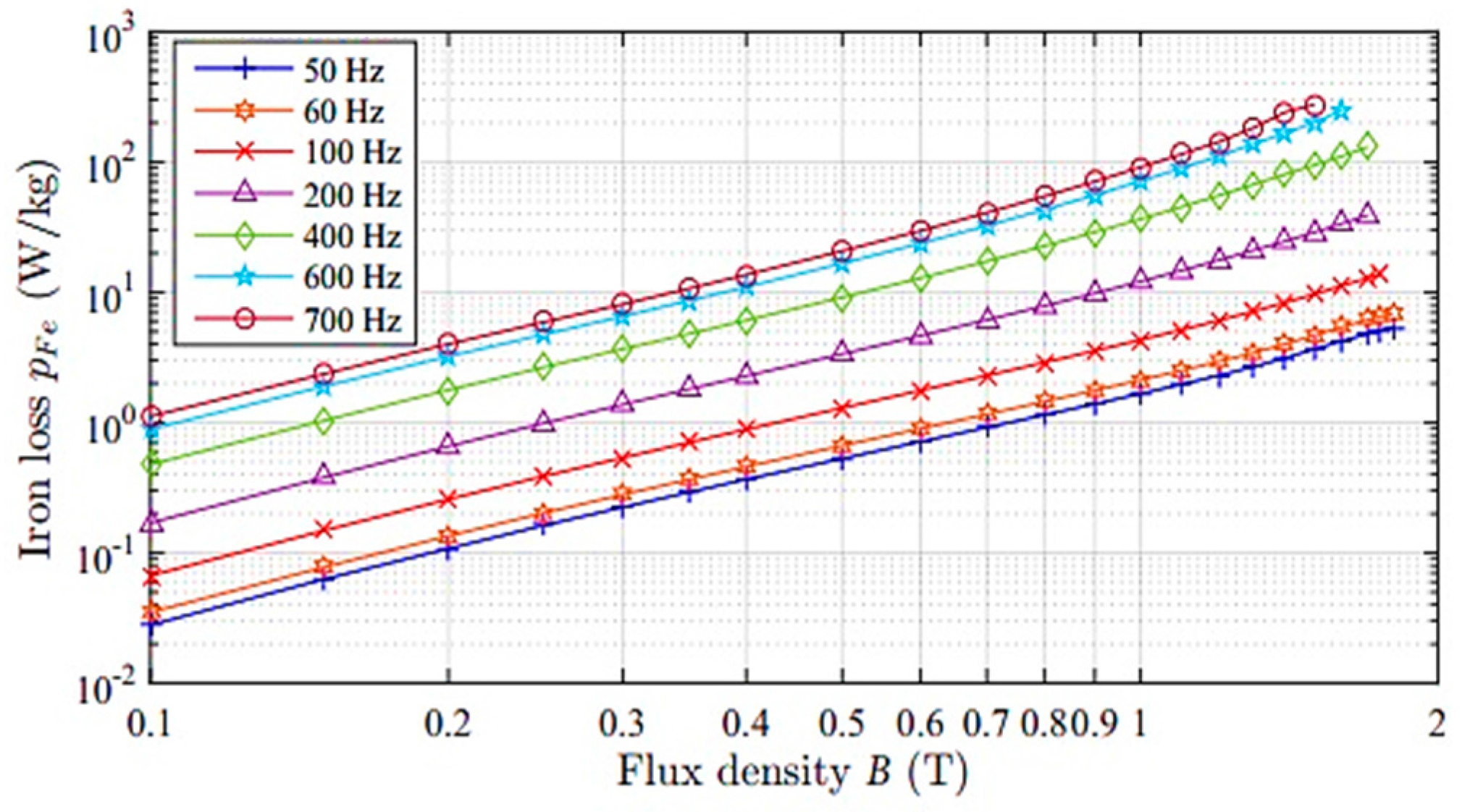
The classic formula is examined for M400-50A steel sheet between 50 to 700 Hz, and is compared to a standard Epstein frame test, which is exhibited in
Figure 1, where solid lines show the analytical data and measured data denoted by markers. The employed Epstein frame comprises a primary and a secondary winding. The sample is evaluated in a set of a number of strips cut from M400-50A steel sheet, in which each layer of the sample is double-lapped in corners and weighted down with a force of 1 N under the well-known International standard for the measurement configuration and conditions (IEC 60404-2:2008) magnetic materials. The iron loss prediction was predicted as acceptable on the steel sheet parts of the machine (approximately linear) for a various range of frequencies (50–700 Hz), and up to 2 T.
Single-valued magnetization curves are employed to consider saturation effects (3) originating from the nonlinear material behavior. The magnetic material is utilized up to 2.1 T in the considered machine. Second-order effects, originating from hysteresis behavior, are neglected:
2.1. Skin Effect Consideration
The eddy-current term of the classic formula is as:
where the coefficient (
a2), which considers the skin effect by accounting for the thickness of the steel used, is:
with the sheet thickness (
d), specific density (
ρ) and specific electrical resistivity (
ρe) of the soft magnetic material.
2.2. Steady-State Equivalent Circuit with Iron Loss Resistance Consideration
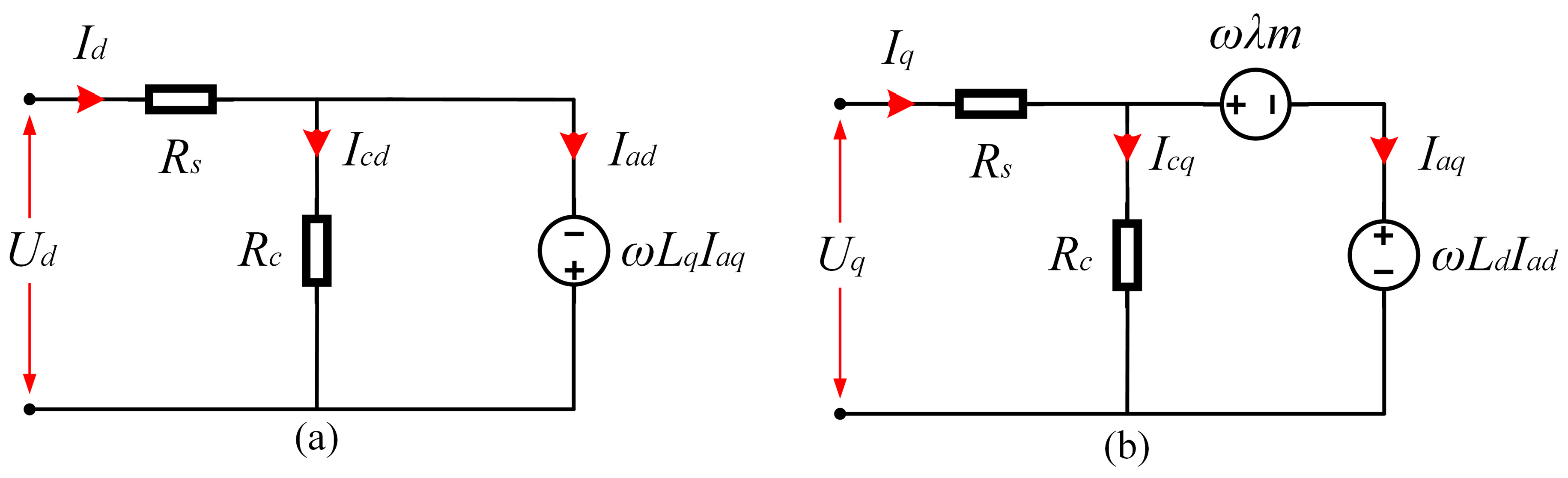
During FWOT, the importance of stator and rotor cores’ resistance as well as its influence on the total iron loss is orderly defined into the d–q-axis equivalent circuit to examine the iron loss evaluation in advance. The steady-state equivalent circuit of the PMSM is shown in
Figure 2 [
22]. Moreover, the voltage drops
RsId and
RsIq of the stator winding resistance are taken into account for the iron loss model based on the equivalent circuit, in which Ref. [
23] assumed the winding resistance negligible. However, its ohmic value can be large, especially under the field weakening condition. Therefore, a more accurate iron loss modelling is rooted from both core and winding resistance consideration. The following expressions can be extracted from the equivalent circuit:
Referring to the above equations, the relation of the iron loss resistance to the magnetic field density waveforms (in the iron parts) can be derived from the analytical calculation of iron loss as follows:
where
Vt and
Vy are the volume of the tooth and yoke in stator.
In a no-load condition, the iron loss
PIEM1 is produced via the no-load fundamental air-gap field density component
Bm1 can be rewritten as follows:
Regarding the analytical procedure, the magnetic induction is calculated once only for the stator yoke, and another time for stator teeth, hence
ktf as the teeth filter constant is defined as:
where α
s is one tooth pitch angle, and
kt (the teeth-width coefficient) base on one tooth pitch (
τs), and one tooth-pitch (
bt) can be calculated by:
Moreover, the magnetic induction calculation at the stator yoke requires another parameter, which is yoke filter constant as:
where
ky as the yoke-height coefficient is:
τp is the pole-pitch in the air-gap, and
by is one yoke-pitch.
In a no-load condition, assuming n current drawn from the machine supply, which means
Id =
Iq = 0, the term
ωλm forces an additional current
Iaq =
−Icq , which is different from zero. Hence, due to the term −
ωLaqIaq in the
d-axis circuit, a current as
Iad = −
Icd will be increased. Furthermore, the back-EMF term of
ωLadIad occurrs in the
q-axis. As a result, the total voltage across
Rc (total stator core resistance) is not only equal to
ωλm, but also back-EMF terms of −
ωLaqIaq and
ωLadIad should be considered. Despite this, these voltage drops are ignored by the work done in Ref. [
23], which causes a considerable error. The modified IEM-Formula, which can be rewritten based on the steady-state equivalent circuit and Equations (4) and (8), is given as:
where the total stator core resistance (
Rc) is comprised of eddy-current loss resistance (
Rce) and hysteresis loss resistance (
Rch), where
Rce is eddy-current loss resistance that depends on the type of used material, its dimensions and other machines’ design factors.
3. Analytical Concept of the Iron Loss Model with Harmonic Loss Considerations
During FWOT, the iron loss cannot be determined accurately using only the magnetic field density because the terminal voltage is steady, being limited with direct current (DC) link voltage. Regarding this issue, a harmonic loss and voltage are induced at the tooth and yoke of the stator core, which are analytically modelled (in Equation (6)) based on the iron loss resistance. Therefore, a large eddy-current loss will be generated, which critically decreases the efficiency, especially if a wide region of FWOT exists. Thus, the IEM-Formula model is adopted with a resistance model that considers harmonic loss. Harmonic loss is investigated through the air-gap magnetic field density harmonics from the elemental component and the machine’s equivalent circuit parameters (shown in
Figure 2), based on the air-gap field density analysis in [
10,
23,
24]. Therefore, the iron loss decreases in a similar manner during FWOT. However, this predicted loss is far from the results from experiments and FEA computation. This is due to the fact that an important eddy-current loss will be generated at FWOT that significantly decreases the efficiency of the machine; this is also validated in [
23,
25]. The iron loss resistance model based on the IEM-Formula should be modified to consider harmonic loss during FWOT for the PMSM with closed-slot, double-layer fractional-slot concentrated winding [
23,
26].
It is required to wind search coils onto armature tooth tips of the tested generator to detect air-gap field. The d-axis pickup should also be installed at the generator to detect the number of revolutions and to synchronize the execution of a program with the revolutions. The d-axis pickup generates a pulse per electric cycle. In addition, the location of search coils at armature tooth tips and at various parts of the rotor and the location of the d-axis and the d-axis pickup in the tested generator. The used methodology is validated in [
27].
By a sinusoidal three-phase current excitation, the total air-gap field density [
28,
29] is written as:
where
Bmg0 and
Bgr are the sum of the no-load magnetic field density and the armature reaction air-gap magnetic field density. For non-sinusoidal waveforms, the eddy-current term in Label (1) can be modified (based on [
24,
25]) to give the following expression:
α is a coefficient that depends on the type and thickness of the laminated magnetic material. In addition,
a2´ =
a2/(2
π2) is the new eddy-current coefficient, and [dB/dt] is the root mean square (rms-value) of the rate of change of field density over one cycle of the fundamental frequency [
29].
Consequently, the predicted iron loss produced in the flux weakening condition with the influence of the harmonic component on the hysteresis loss is found to be small (about 9% of total iron loss) under open-circuit condition; therefore, its effect on the hysteresis term is neglected. Hence, the modified eddy-current loss density in W/m
2 is proportional to the energy of the differential of the field density, which mainly originated via the eddy-currents behavior that is modelled by Equation (16), and specific field density distribution over tooth (
Bt) and yoke (
By) shown in Equation (17), given as:
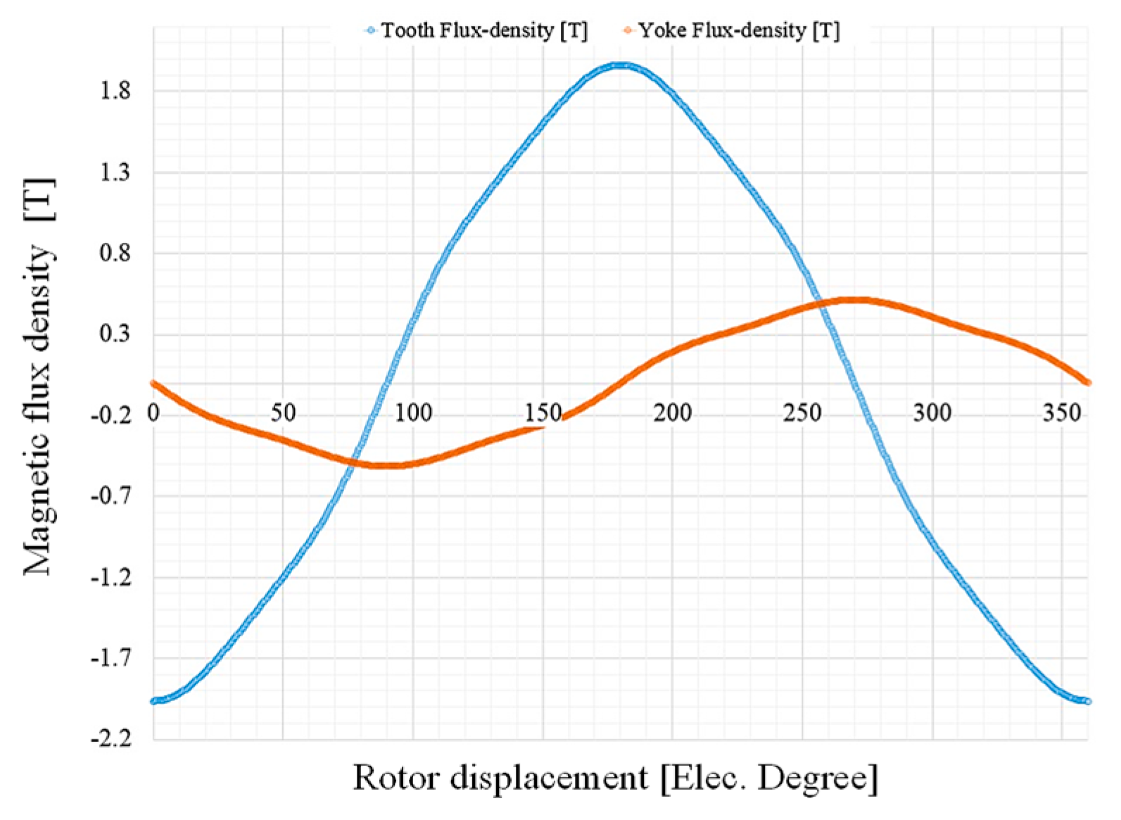
The magnetic field density distribution over (
Bt) and (
By) is presented in
Figure 3, in which peak values are 1.98 T and 0.56 T, respectively. To simplify the above equation:
where
Bg is the airgap magnetic induction between one tooth pitch. The teeth and yoke filter constants (
ktf and
kyf), which are dependent on harmonic order, can be calculated using Equations (9) and (11).
bt = 15 mm, and
by = 81 mm in this study.
As a result of Equations (16)–(18), the following summed equation can be written to calculate the model-based parametric eddy-current loss equation, given as:
As the generated synchronous air-gap magnetic field density is caused from the fundamental air-gap field density and harmonic component (
Bsyh), it can be expressed as:
with fundamental form as [
23]:
where
Fs1 is the fundamental magnetic motive force (MMF) in the stator,
ksw constant is a unit square function and through Fourier series can be developed to:
where
αp is the pole-arc coefficient.
The ratio of the harmonic field density to the fundamental term can be given as [
24]:
Considering (
h = 1) as fundamental,
Ph can thus be rewritten in the following form:
kph as a harmonic constant is employed to include the harmonic magnetic induction range, which can be known from the machine design parameters [
23]. In addition, a harmonic voltage
Uph originated from Labels (6), (21) and (22) are defined to model harmonic loss based on equivalent circuit parameters, which is:
Regarding the armature reaction air-gap magnetic induction, the equivalent factors are affiliated with the machines’ parameters like Equations (27) and (28), which are coupled with the
d–
q axis equivalent circuit as:
To simplify the harmonic voltage Equation (23), the combination of Equations (23) and (24) results in the new fundamental (
h = 1) expression as given:
By adopting the harmonic voltage
Uph, the harmonic loss
Ph Equation (24) can be simplified into the formula of
Uph and
kph as:
The modified IEM-Formula based on the harmonic loss can be derived from the parametric machine modelling based on the machine’s equivalent circuit parameters as:
where
PIEM1 and
Ph are the classic IEM-Formula and modified IEM-Formula (which considers iron loss resistance) and harmonic iron loss.
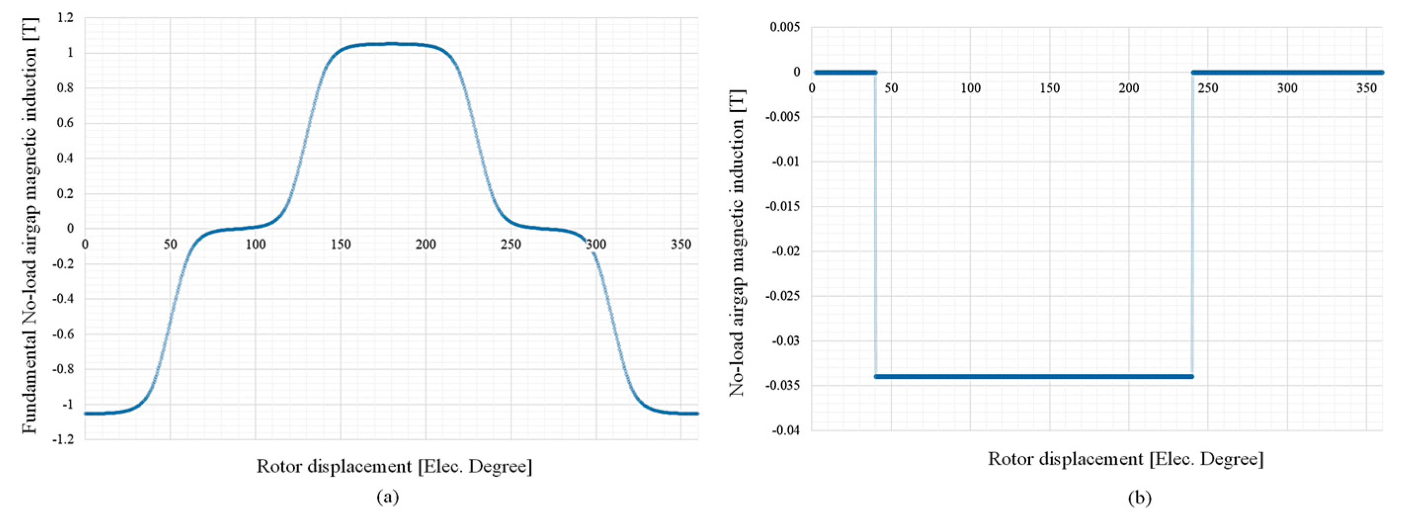
Figure 4a reveals the no-load air-gap magnetic field density (
Bm) and fundamental no load magnetic field density (
Bm1) in
Figure 4b, utilized from Labels (21) and (27). The waveforms for a range of 360
θe (electrical degree) rotor displacement are shown in
Figure 4. The remaining harmonic component waveform of
Bm can be calculated through the difference between
Bm1 and
Bm [
28].
4. Results and Discussion
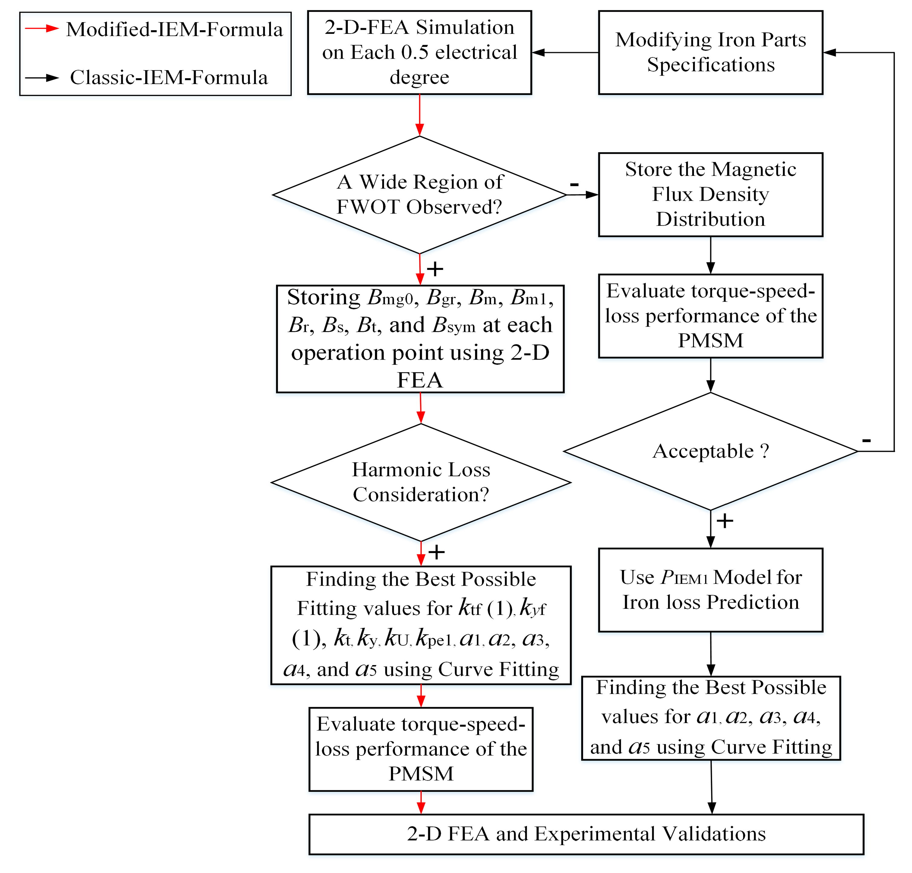
After the analytical and numerical modelling by the modified IEM-Formula, a wide region of FWOT is observed. Hence, a significant harmonic loss is produced, which causes a considerable increase in iron loss. Since a large deviation in iron loss prediction using the classic IEM-Formula can be seen in comparison with test results, an IEM-Formula-based modification on the equivalent circuit of the PMSM is proposed to consider harmonic losses.
Figure 5 contains a flowchart illustrating the calculations on a fractional-slot concentrated winding, radial field permanent magnet machine with 6 kW rated power in generator-mode. The figure also shows the results of the analysis during FWOT. The total iron loss using classic IEM-Formula (red curve) sharply diverges; however, the modified IEM-Formula (green curve) along with the experimental results rapidly increases during FWOT.
Table 1 presents the sizeable dimensions and specifications of the prototype PMSM.
Table 2 illustrates the value of the coefficients.
First, a large range of FWOT is observed and the previously mentioned magnetic field density components are stored using 2D FEA for each 0.5 electrical degree. Second, the coefficients are calculated using a curve fitting technique based on the multi-generalized reduced gradient nonlinear (M-RGN) method [
30].
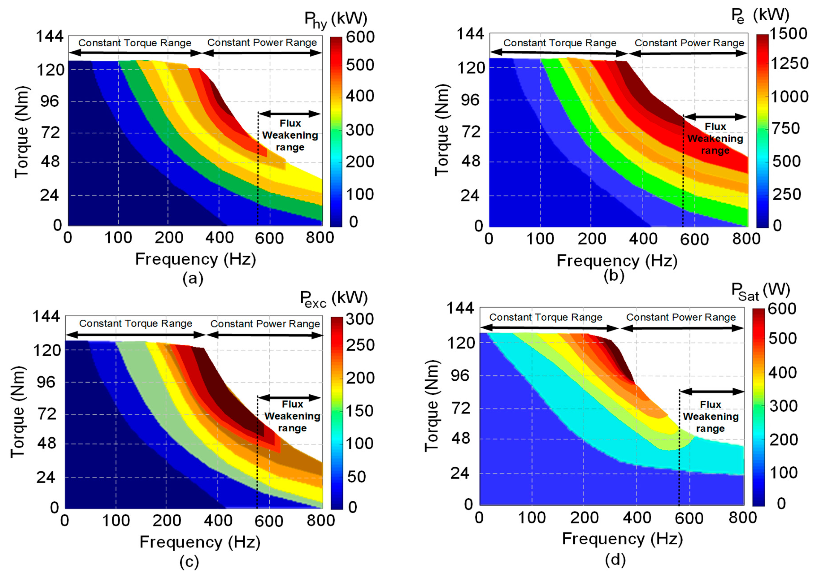
Figure 6 illustrates the behavior of torque-frequency-loss of the machine, in which the terms of the iron loss such as hysteresis, eddy-current, excess, saturation, and harmonics are calculated from the modified IEM-Formula. The Hysteresis loss (
Figure 6a), eddy-current loss (
Figure 6b), excess loss (
Figure 6c), and saturation loss (
Figure 6d) are shown based on their constant torque and power range with a considerable field weakening region.
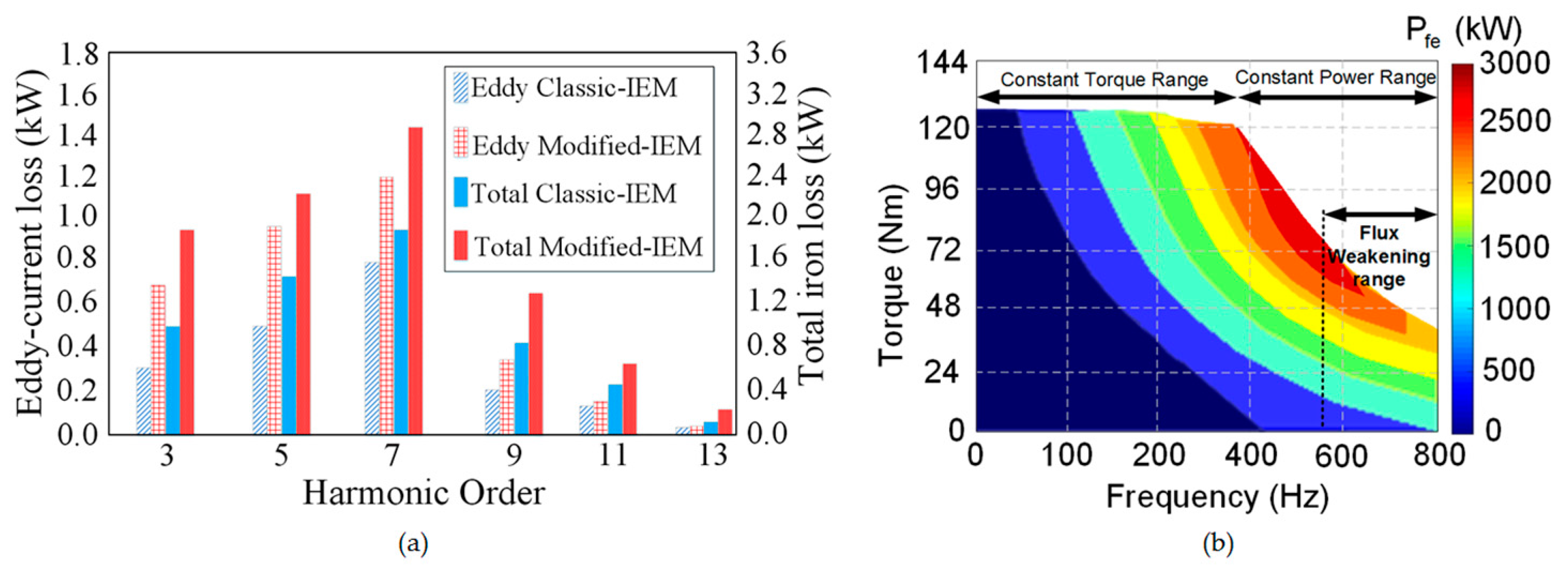
Figure 7a proves the generated harmonics perspective of eddy-current and total iron losses by the classic and modified-IEM-Formula. A considerable difference in the total iron loss and also efficiency during FWOT can be seen between the two methods.
Figure 7b shows how the following terms in
Figure 7a are representing the total iron loss prediction based on torque-frequency-loss evaluation.
5. Experimental Verification
A surface mounted permanent magnet synchronous generator with 36 slots for a vast operating range of 6 kW (nominal power) is manufactured with the listed sizeable dimensions and specifications, which are reported in
Table 1. The stator and rotor cores both are made of M400-50A steel sheets. The modified IEM-Formulas’ coefficients are extracted by numerically fitting the no-load experiment results combined with FEA results. The no-load iron loss is measured through the difference between the total no-load loss and mechanical loss. First, the prototype PMSM is dragged under the no-load condition and tested the total no-load loss curve versus the speed. This total no-load loss
Pfe (total) consists of the no-load iron loss
Pfe and the mechanical loss
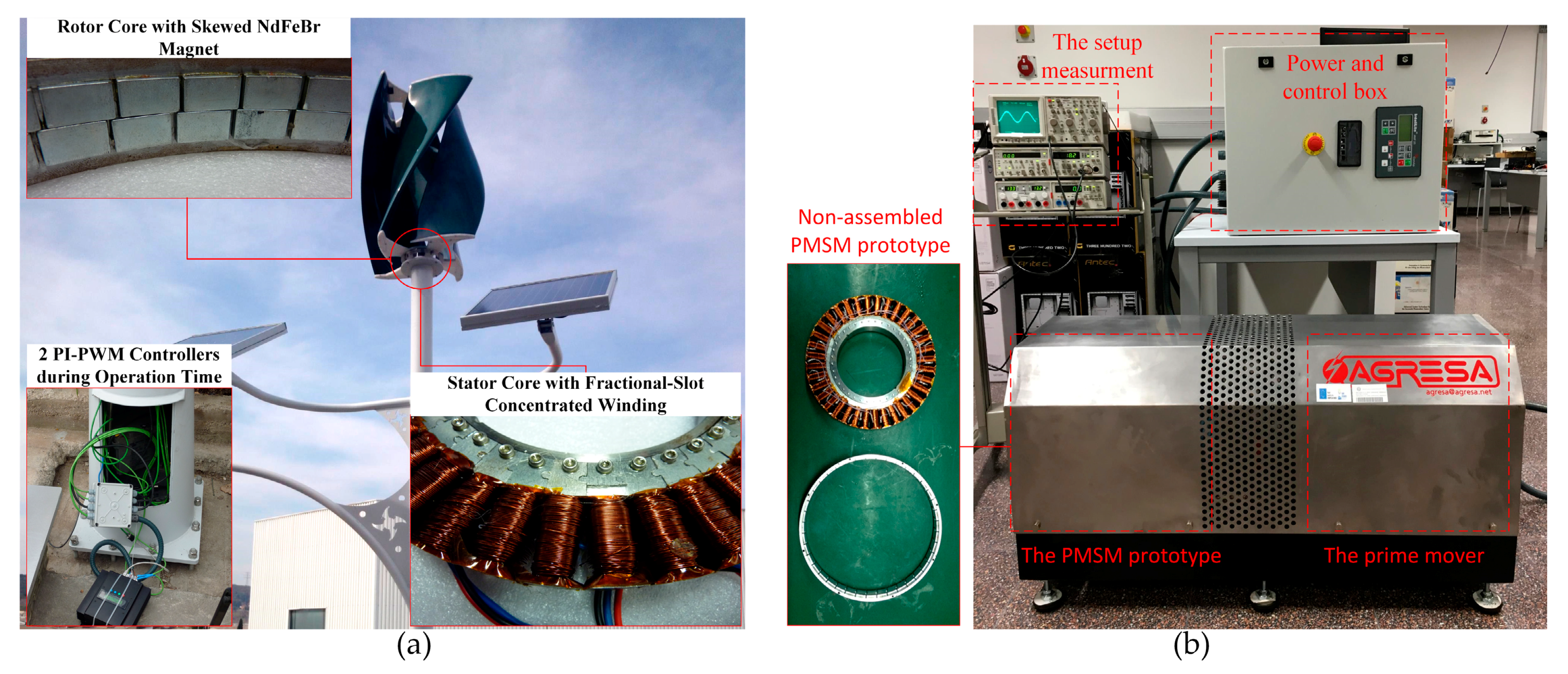
Pmech. The PMSG under testing is fed by a variable-speed frequency converter (ABB ACS600) and loaded by a DC machine (prime mover). The shaft torque is measured by a torque transducer (TORQUEMASTER TM-214). The electrical power (input and output) is measured by a power analyzer (Yokogawa PZ4000). Afterwards, all the data (such as voltage, torque, power, and efficiency) were stored by a reading unit to the laboratories’ computer. The prototype machine is designed particularly for laboratory test use. As the output power is stored by a dynamometer. Thus, the total loss (consists of copper, iron, and mechanical losses) has been obtained by a simple subtraction between input and output powers. The copper loss has been calculated via the measured phase current and resistance, as well as the mechanical loss being provided in the coefficient extracting experiment.
Figure 8a demonstrates the manufactured stator and rotor cores, and the two proportional integral-Pulse Width Modulation (PI-PWM) units as a part of the control system in a wind power application, in which a vertical-axis wind turbine is employed [
31]. A test bench prototyping platform composed of a 6 kW synchronous wind generator with a 1024 points absolute encoder, current sensors and a power brake controlled load is also shown in
Figure 8b.
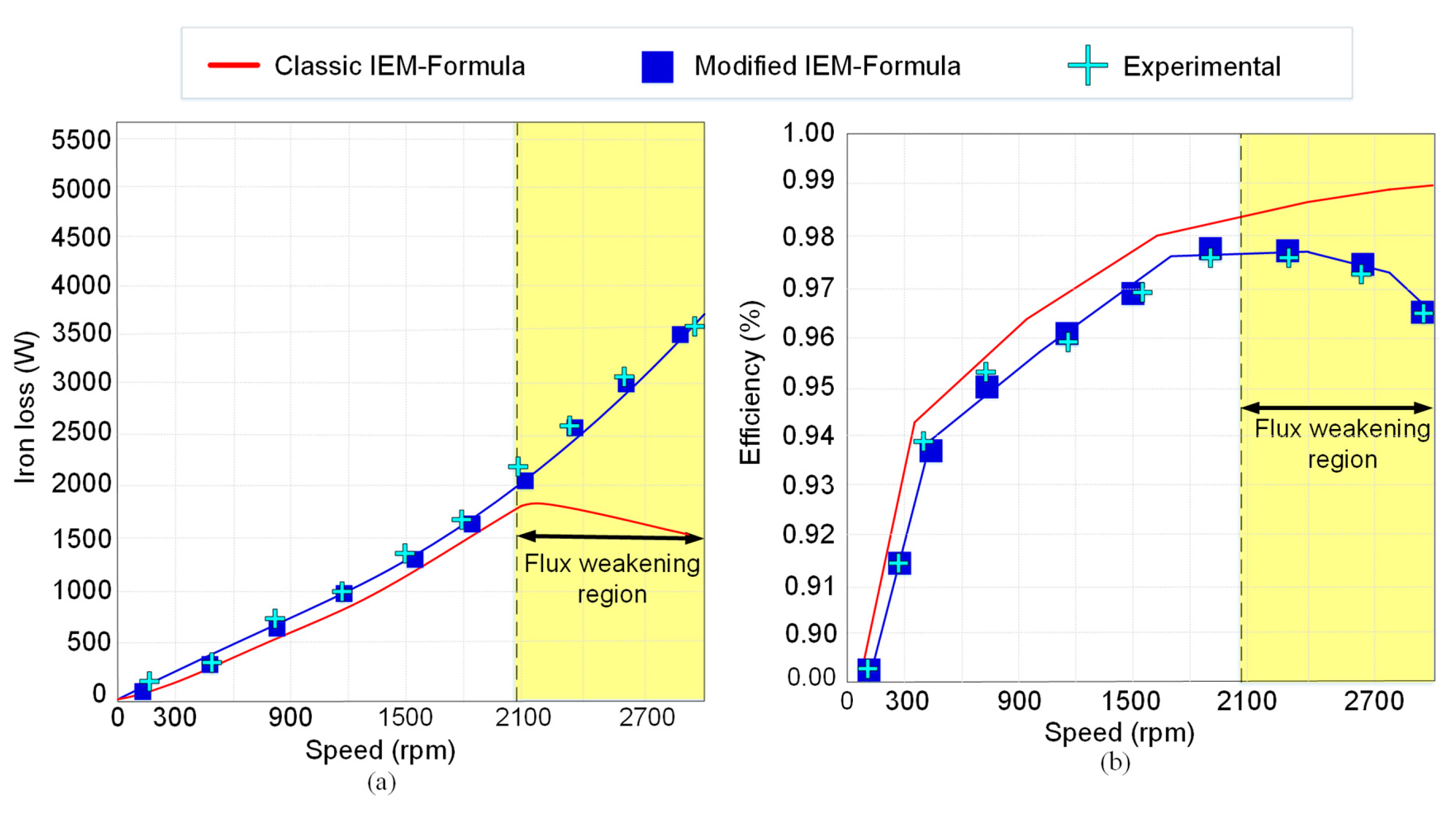
Figure 9 illustrates the influence of the modified IEM-Formula on the total iron loss and efficiency with 3D FEA and experimental verifications for the studied PMSG. From the standpoint of the classic IEM-Formula model, the iron loss resistance is the parallel connection of the hysteresis losses and the eddy-current losses. This is examined through the air-gap field density with the motor speed as the operation parameter. While the PMSM operates in the field weakening region, the terminal voltage remains changeless because it is diminished by the DC link voltage. As predicted by the classic IEM-Formula model, the iron loss resistance rises with the speed, shown in (18). Thus, the iron loss decreases in a similar manner during field weakening operation. However, this predicted result is far from the results from the experiments and FEA calculation. This is due to the fact that large eddy-current loss is generated during the field weakening, rapidly decreasing the efficiency of the machine.
Figure 9a shows the comparison of iron loss obtained by the proposed PMSM for the classic IEM-Formula, the proposed modified IEM-Formula, 3D FEA and experimental measurement. The classic IEM-Formula shows significant deviation during FWOT from the modified formula, which shows worthy agreement with experimental and 3D FEA results. This result presents that the harmonic loss must be considered if a wide FWOT exists.
Figure 9b presents how the efficiency calculation might create a considerable error during FWOT. The error between the proposed model and experiment results is due to neglecting the slot opening effect and fringing effect. However, the iron loss predicted by the classic IEM-Formula is obviously underestimated, particularly during the field weakening region, due to ignoring the harmonic loss.


