Article

The Setup Design for Selective Laser Sintering of High-Temperature Polymer Materials with the Alignment Control System of Layer Deposition

by
Alexey Nazarov
1,
Innokentiy Skornyakov
1 and
Igor Shishkovsky
1,2,*
1
Moscow State University of Technology “STANKIN”, Vadkovsky Per. 1, Moscow 127055, Russia
2
Lebedev Physics Institute of Russian Academy of Sciences, Samara Branch, Samara 443011, Russia
*
Author to whom correspondence should be addressed.
Machines 2018, 6(1), 11; https://doi.org/10.3390/machines6010011
Submission received: 21 January 2018 / Revised: 2 March 2018 / Accepted: 5 March 2018 / Published: 5 March 2018
(This article belongs to the Special Issue Process Innovation in Digital Manufacturing)

Abstract

:
This paper presents the design of an additive setup for the selective laser sintering (SLS) of high-temperature polymeric materials, which is distinguished by an original control system for aligning the device for depositing layers of polyether ether ketone (PEEK) powder. The kinematic and laser-optical schemes are given. The main cooling circuits are described. The proposed technical and design solutions enable conducting the SLS process in different types of high-temperature polymer powders. The principles of the device adjustment for depositing powder layers based on an integral thermal analysis are disclosed. The PEEK sinterability was shown on the designed installation. The physic-mechanical properties of the tested 3D parts were evaluated in comparison with the known data and showed an acceptable quality.

Graphical Abstract

1. Introduction

Selective laser sintering (SLS) is one of the most famous and commercially successful methods of additive technologies [1,2,3,4,5]. The SLS makes it possible to manufacture products with a unique internal and/or external surface shape and perspective physical and mechanical properties [1,2,3,4,5]. At the same time, there are a number of promising polymer powder materials that differ from those traditionally and long used in the technology of SLS—nylon [6,7], polycarbonate [8,9,10,11,12], polyamides [13,14,15,16,17], polyethylenes [18,19], or ferrielectric polyvinylidene fluorides [20] and so on—by a combination of high heat resistance, durability, and a wide range of interesting physic-mechanical and chemical-biological properties [21,22,23,24,25,26].
Particularly interesting are the parts manufactured by the SLS technology from some types of powders based on polyetheretherketone (PEEK). They have high strength values of up to 95 MPa (vs. 45 MPa for conventional polyamides) and Young’s modulus of up to 4400 MPa (vs. 1500 MPa for conventional polyamides) [3,27,28,29]), have high heat resistance (maintenance of physical and mechanical properties during short-term exposure to temperatures up to 310 °C and long-term exposure to temperatures of 260 °C), as well as excellent biocompatibility and insulating (dielectric) properties [29,30,31,32]. A set of these properties in combination with the capabilities of the SLS method allows creating unique parts. These parts are increasingly used in the aerospace industry, medicine, and motorsport [29,30,31,32]. A set of these properties in combination with the SLS capabilities allows creating unique details. These parts are increasingly used in aerospace, medicine, and auto- and motorsport [29,30,31,32]. The authors know a limited number of additive setups are operating in the framework of the SLS technology with different types of polymer powders. In general, the world-famous additive technology giants—3D Systems and EOS GmbH (Krailling, Germany) [33,34] produce, however, only a few EOS system pieces of equipment to operate with heat-resistant polymers. The small number of the SLS setups applying the promising heat-resistant polymer powders limits the business and industry opportunities involved in the development and production of science-intensive products.
This paper’s goal is to present the design of the SLS facility (hereinafter referred to as SLS-machine), which uses high-temperature polymers. We propose original solutions for the alignment control system of the powder delivery layers under layerwise SLS materials based on PEEK.

2. Equipment for Plastic Additive Manufacturing

2.1. Analysis of Analogue Equipment

The literature analysis of analogue installations of the world’s leading manufacturers [33,34] showed that there is only one producer of additive equipment in the world—Electro Optical Systems (EOS, Krailling, Germany), which successfully implemented the high-temperature PEKE into the SLS process [27]. This is a well-known family equipment of the type Eosint P, from which the P500 and P800 systems [35,36] used the PEEK polymer, and the parameters of which are presented at the indicated links on the manufacturer’s website. The policy of this company boils down to the fact that, together with the SLS machine, the customer is supplied with the proprietary software which makes it impossible to control part of the manufacturing process. Besides, the machine can only operate with one type of the PEEK powder (grade EOS PEEK HP3), which is only tested and supplied by the machine manufacturer. In the scientific and technical literature, there is no information on the Eosint P500/P800 technical characteristics (except for those listed in the brochures and on the official website), nor on the constructive decisions taken in its development. It is only known that the Eosint P800 is a result of a serious modification of the Eosint P760 machine, taking into account the heating of the workspace up to 385 °С.
In the Eosint P500 machine, the operating temperature is already ~300 °C. However, the creators note that the Eosint P500 is operated simultaneously by two 70 W lasers, and a new design of the recoater and the preheating of the changeable frame are applied. These innovations, according to the creators, significantly increased the productivity of the process of manufacturing parts from high-temperature polymers [35]. According to the designers, this brought the rate of the application of the layers to 0.6 m/s.

2.2. Known Features of the SLS Process for Heat-Resistant PEEK

From the literature sources [27,30,31], it is known that the best physical and mechanical characteristics are represented by the PEEK parts manufactured using special SLS technology. This technology has a number of fundamental differences from the SLS technology for conventional polymers.
The main stages of the SLS technology for manufacturing the PEEK parts are described below (Figure 1):
(a)
The heaters built into the platform and the changeable frame are heated up to a temperature of ~360 °С;
(b)
The protective gas (nitrogen) is pumped through the airtight chamber to obtain the required purity, and the entire SLS machine is held for two hours till uniform heating of all its elements in order to avoid their thermal deformation during operation;
(c)
The platform is lowered to the thickness of the first powder layer to be applied (usually ~120 μm);
(d)
The recoater (in the form of a double knife) moves to the left limit position under the splined shaft and the required powder batch is dosed to the recoater with the help of the splined shaft;
(e)
The recoater moves to the right limit position (shown in phantom) applying and leveling the first layer of powder on the platform during the movement;
(f)
The applied powder layer is heated up to ~385 °C with the help of upper heaters;
(g)
The platform is lowered to the thickness of the second powder layer to be applied (usually ~120 μm);
(h)
The recoater moves to the left limit position and with the help of the splined shaft and the powder delivery hopper applies in a similar way the second powder layer over the first layer on the platform, dropping excess powder into the powder collecting hopper;
(i)
The process of applying preliminary powder layers (about 50 layers in total) is carried out according to the c–h points without laser treatment. It is necessary for uniform heating of the machine together with the powder, and also for checking the correctness of the recoater knife position relative to the platform. During this stage, the heaters maintain the constant temperature (about 360 °C) of the whole powder volume;
(j)
The part manufacture begins when the recoater knife is set correctly relative to the platform;
(k)
The 51st layer of powder is applied over the 50 heated powder layers;
(l)
The 51st powder layer is heated to 385 °C with the help of upper heaters;
(m)
Powder is sintered with a laser beam in the individual zones of the applied layer depending on the shape of the part being manufactured;
(n)
Then, a new layer of powder is applied and the process is repeated until the part is completely manufactured;
(o)
After the whole part construction, it is cooled down very slowly (the cooling time is usually twice as long as the time of the part construction) together with the volume of the unsintered powder in the SLS machine in the changeable frame by means of heater control;
(p)
After complete cooling of the part together with the unsintered powder, the changeable frame is removed from the SLS machine and moved to the cleaning station where the part is cleaned from the unsintered powder.

3. Main Technical Characteristics and Requirements for the Developing Equipment

For manufacturing various large capacity parts (see Section 2.2), the following technical requirements (the most complicated characteristics) were imposed on the SLS machine:
i.
the possibility of using the SLS technology for various types of the PEEK-based powders;
ii.
the workspace of 500 × 500 × 300 mm3 (length × width × height);
iii.
preheating of the applied powder layer to 385 °С with an accuracy ±2 °C (over the entire area of 500 × 500 mm2);
iv.
nitrogen protective atmosphere (nitrogen purity: up to 99.8%);
v.
the accuracy of the applied powder layer ±10 μm;
vi.
the capability to maintain controllable slow cooling of the entire volume of the manufactured part together with the unsintered powder from 385 °C to 20 °C;
vii.
the capability of automated control of the powder recoater alignment;
viii.
the possibility of changing the intensity distribution into the spot of laser radiation from “gauss” to “reverse gauss” or “top hat”, which in the opinion of some researchers, can improve the quality of the components produced by the SLS method [36,37,38].
Named technical characteristics and requirements for the machine under development (in combination with the peculiar features of the SLS technology for the PEEK-based powders) complicate the task of the design development because of the following problems:
  • the thermal deformations in the installation mechanical elements (for example, at the peak of heating, the upper heaters can reach 2600 °C [39,40], and most of the remaining elements of the machine are at room temperature);
  • use of special materials for parts and assemblies under heating. For example, for springs whose alloys lose their mechanical properties during heating (spring alloys A 29 1060 ASTM, A 576 1060 ASTM, 5147 ASTM, 6150 ASTM, 9262 ASTM, etc., which are designed for operation at temperatures up to 400 °C);
  • thermal deformation of the laser-optical unit of the installation, thermal aberrations, up to the destruction of protective glasses, lenses, mirrors, etc., at high temperatures;
  • the property change in the optical elements of the laser-optical assembly of the installation due to heating. For example, it is changing the refractive index of the protective glass in a complex scanner lens (f-theta lens);
  • the chamber sealing (most standard silicone seals and sealants really work at temperatures up to 300 °C);
  • thermal insulation of the working chamber (space where the part is made from the remaining elements of the installation, for example, the precise drive of the vertical movement and alignment, the device for depositing the powder layers, the laser-optical unit, etc.);
  • an interactive system for the thermal picture monitoring during the SLS process;
  • the protection of electrical components (induction position sensors, contact sensors of emergency situations, electric wires, electrical connectors, etc.), used up to a temperature of 50–70 °С.

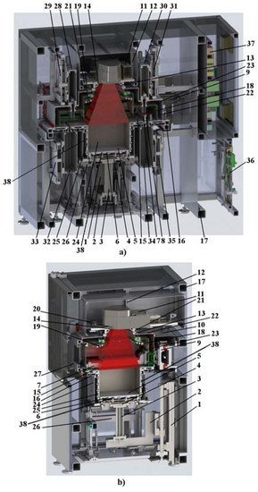
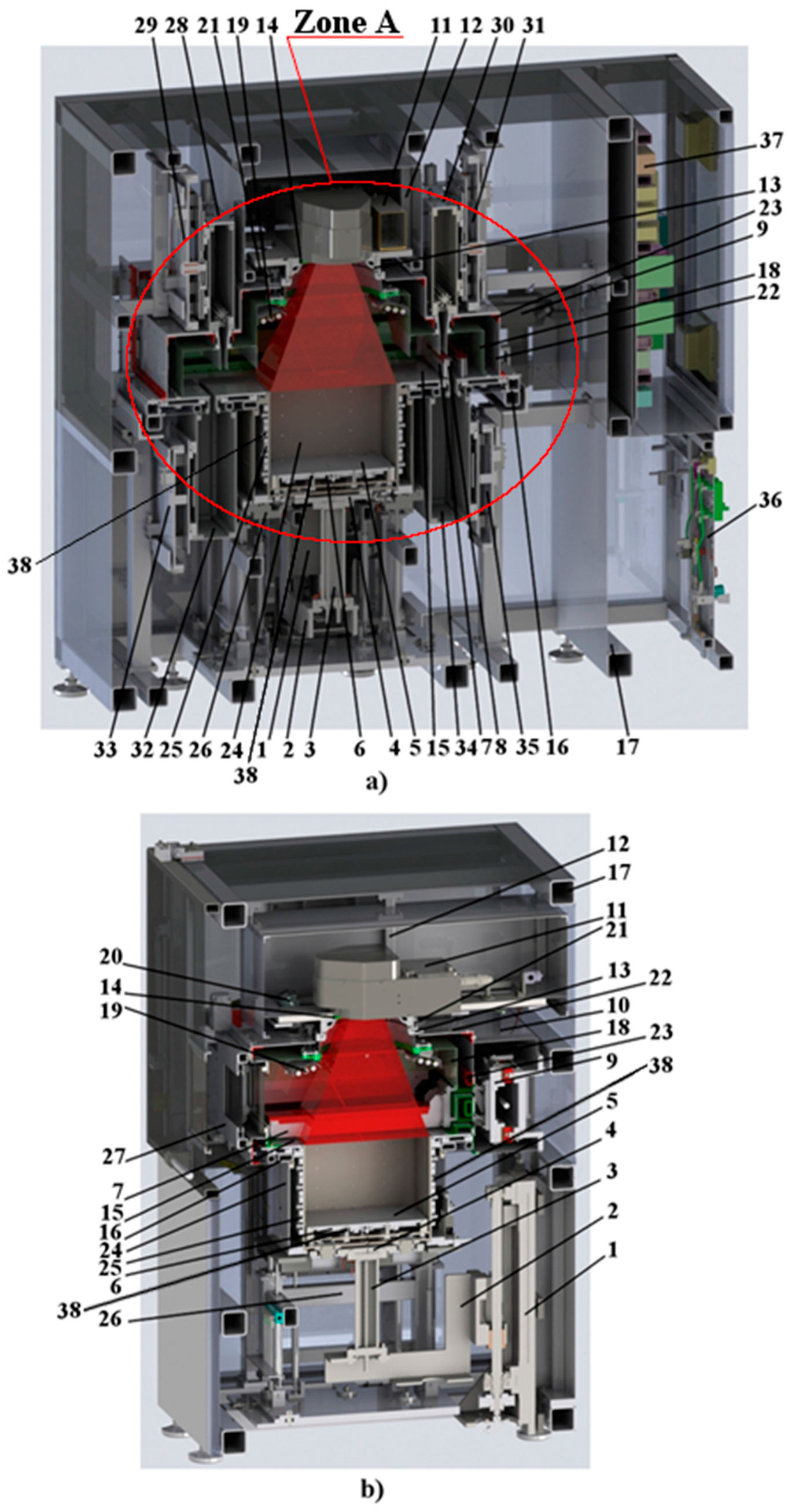
4. Design and Technological Solutions for the High-Temperature Plastic SLS Machine

The appearance of the SLS machine is shown in Figure 2. The unit is equipped with the separate nitrogen generator and the cooling station, which is conditionally removed in Figure 2. The longitudinal and cross section of the SLS machine with the main nodes are shown in a drawing in Figure 3. The kinematic scheme of the SLS machine is shown in Figure 4. The laser-optical scheme of the SLS machine is shown in Figure 5.
During the equipment design, the two conflicting tasks had to be constantly addressed:
(1)
in the nitrogen protective atmosphere (99.8% purity), it was necessary to pre-heat the applied powder layer to 385 °C, (due to the peak heating of the upper heaters to 2600 °С [38,39]), and also to support the entire volume of the manufactured part together with the unsintered powder at a temperature of 360 °C, with subsequent slow controllable cooling to 20 °C;
(2)
it was also necessary to maintain the accuracy of the deposited layer of powder at 120 ± 10 μm over the entire working area of 500 × 500 mm, and also to keep the focused laser spot and the accuracy of its positioning during laser processing.
So complex is it that at the same time it was necessary to apply even and uniform layers over a large area of 500 × 500 mm, but all the main elements of the installation were located in the direct vicinity of the working area, subject to significant alternating heating. We are talking about (check by Figure 3): 7—recoater; 8—double knife; 9—recoater drive; 1—lower transition table precision vertical drive, 11—laser-optical unit; 12—laser-optical unit frame; 13—ring of laser-optical unit; 14—ZnSe-glass; 17—main frame of the SLS machine and all. These difficulties required creation of the thermal protection circuits for the main elements of the installation.
Problem 1 was solved thanks to the following technical solutions (Figure 3). We used:
  • quartz halogen heaters—19 [39,40], installed in the upper part of the sealed inner chamber and combined in the heating system of the applied layer of powder;
  • flat ceramic heaters [41,42], built into the work table and combined into the heating system of the platform—6;
  • flat ceramic heaters—25 [41,42], built into the interchangeable production bunker and integrated into the heating system of the replacement manufacturing hopper.
Figure 3 shows the setup structural plan, which includes the following items: a—longitudinal section (axonometry), b—cross-section (axonometry). The SLS machine includes the following main units, systems and parts: 1—lower transition table vertical drive, 2—lower transition table bracket; 3—lower transition table cooled rod; 4—lower transition table (has the ability to automatically engage with and disengage from the building platform); 5—building platform; 6—building platform heating system; 7—recoater; 8—double knife (only Figure 3a); 9—recoater drive (only Figure 3b); 10—airtight casing of recoater (only Figure 3b); 11—laser-optical unit; 12—laser-optical unit frame; 13—ring of laser-optical unit; 14—ZnSe-glass; 15—powder depositing main plate; 16—main plate frame; 17—main frame of the SLS machine; 18—airtight inner chamber; 19—top heaters; 20—pyrometer (only Figure 3b); 21—illumination lamp; 22—protective external chamber; 23—external chamber frame; 24—changeable frame; 25—changeable frame heating system; 26—changeable frame clamping device; 27—double-protective door (only Figure 3b); 28—left powder delivery hopper (only Figure 3a); 29—left powder delivery hopper clamping device (only Figure 3a); 30—right powder delivery hopper (only Figure 3a); 31—right powder delivery hopper clamping device (only Figure 3a); 32—left powder collection hopper (only Figure 3a); 33—left powder collection hopper clamping device (only Figure 3a); 34—right powder collection hopper (only Figure 3a); 35—right powder collection hopper clamping device (only Figure 3a); 36—air-gas system; 37—electric control device; 38—thermocouple.
Control of the accuracy of preheating the applied powder layer to 385 °C was carried out by means of the pyrometer—20 (Figure 3b), installed in the upper part of the protective chamber.
Maintenance control of the entire volume of the workpiece together with the unsintered powder at a temperature of 360 °C in a closed loop followed by a slow controlled cooling to 20 °C is achieved thanks to the thermocouples—38, installed in the central cut-out in each flat ceramic heater—25 and in each flat ceramic heater in the heating system of the working platform—6.
The closed loop problem was solved through the introduction of additional water, gas, and air cooling circuits, which prevent the SLS machine elements from thermal deformation and protect the electrical connectors, sensors, optical, and other SLS machine elements from overheating as the machine elements cannot operate under heating by more than 40–70 °C. In other words, it was possible to isolate the working space heated up to 385 °С together with the volume of the manufactured part and the powder not yet processed from all the units and devices responsible for the exact deposition of the powder layers and material fusion with a laser.
In the kinematic scheme of the SLS machine (Figure 4), we proposed the following most interesting technical solutions:
-
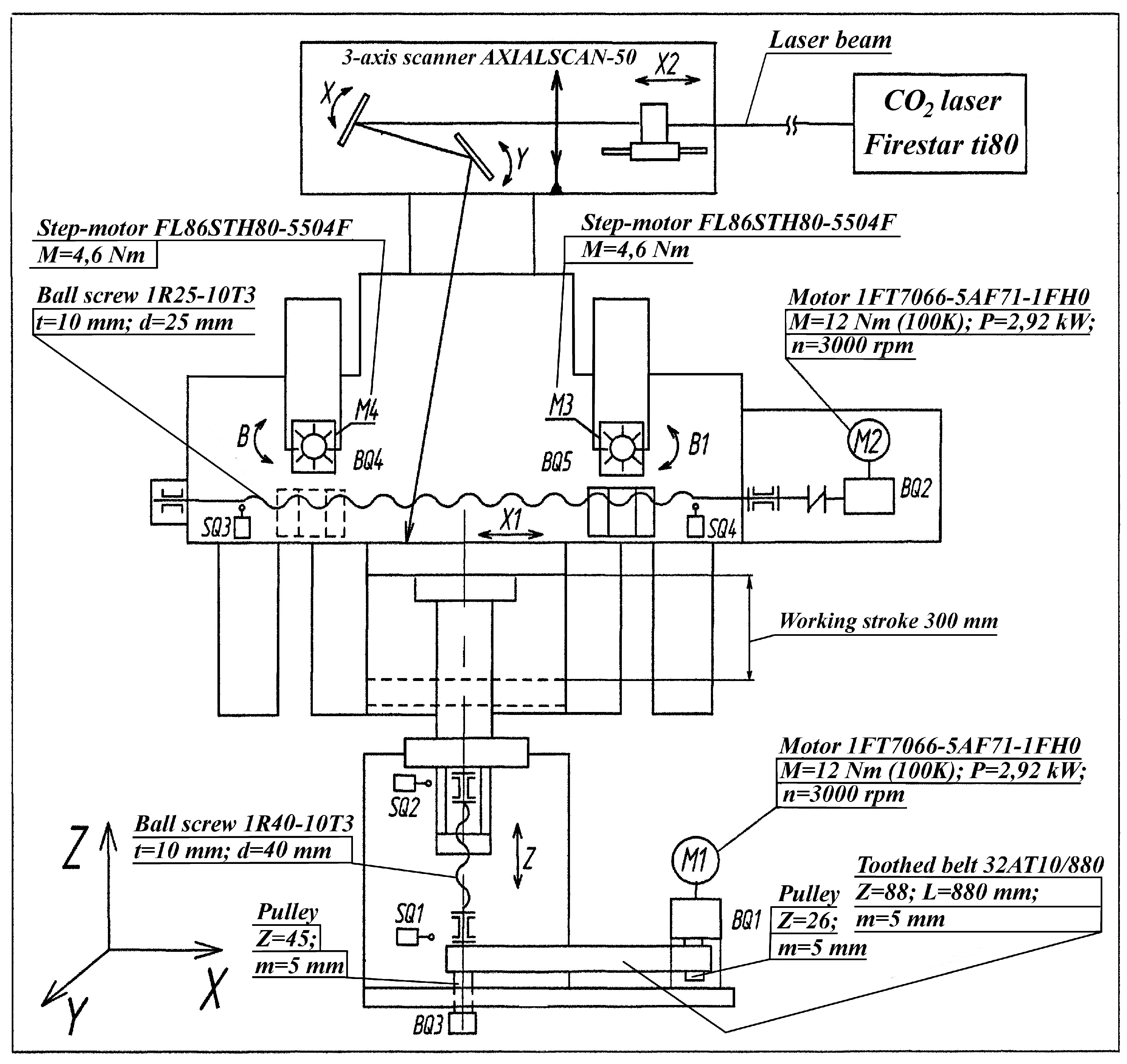
vertical movement of the desktop is realized thanks to a ball screw rotated from the servomotor, which is a traditional solution for such nodes in a variety of SLS installations;
-
the horizontal movement of the powder layer’s delivering device is realized by means of a ball screw rotated from the servomotor. This fundamentally differentiates our equipment from those of other manufacturers, which often use a belt drive stretched between the two rollers to realize horizontal movement. However, the experience of operating the belt drive stretched between the rollers has shown its unreliability due to periodic clogging of the tension rollers with powder, which leads to frequent drive failures;
-
dosing of the necessary powder portions is realized thanks to splined shafts, rotated by stepping motors, which is a classic solution for modern SLS machines working with polymer powders;
-
for the prevention of emergency movements of the nodes, end position sensors are provided;
-
for precise tracking of the movement, the sensors of the coordinate control are applied.
The main cooling circuits of the machine are shown in Figure 5. They include the following items: 1—air cooling of the protective ZnSe-glass from the scanner side; 2—nitrogen cooling of protective ZnSe-glass from the side of the ring of laser-optical unit; 3—nitrogen cooling of recoater drive; 4—water cooling of the main plate applying the layers of powder; 5—water cooling of the flange of the ring of the laser-optical unit, on which the protective ZnSe glass is mounted; 6—water cooling of the cooled rod for moving the lower transition table; 7—water cooling of the plate of the clamping device of the changeable frame; 8—nitrogen cooling of the optical part of the pyrometer; 9—water cooling of the pyrometer case; 10—air cooling of electrical connectors of the lower transition table and building platform. All the inductive position sensors in the tightening device of the changeable frame are provided with the local airflow to prevent overheating (not shown). Nitrogen cooling of the illumination lamp has been implemented (not shown). Temperature control points using a manual pyrometer for metals are: 11—head bearing of ballscrew; 12—lower transition table bracket; 13—lower transition table of cooled rod; 14—plate of laser-optical unit (rear edge); 15—plate of laser-optical unit (middle); 16—plate of laser-optical unit (first line); 17—ballscrew; 18—pulley; 19—plate of recoater drive; 20—ring of laser-optical unit; 21—plate of double-protective door; 22—point on the plate near connector.

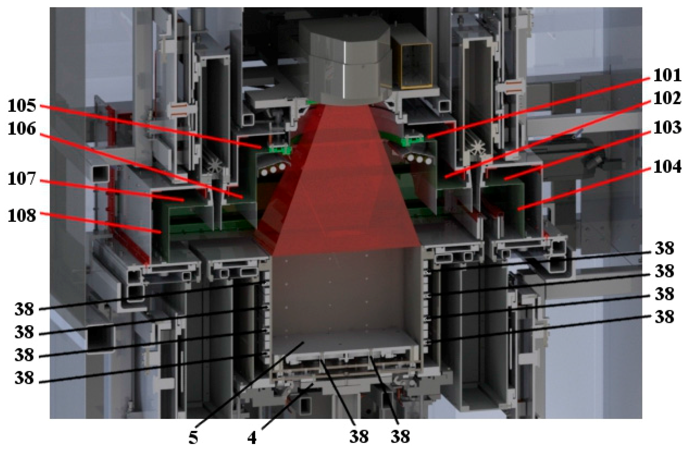
5. Adjustment Control System for Powdered Layer Delivery

The following most interesting technical solutions are visible from the developed scheme of the laser-optical node (Figure 6):
-
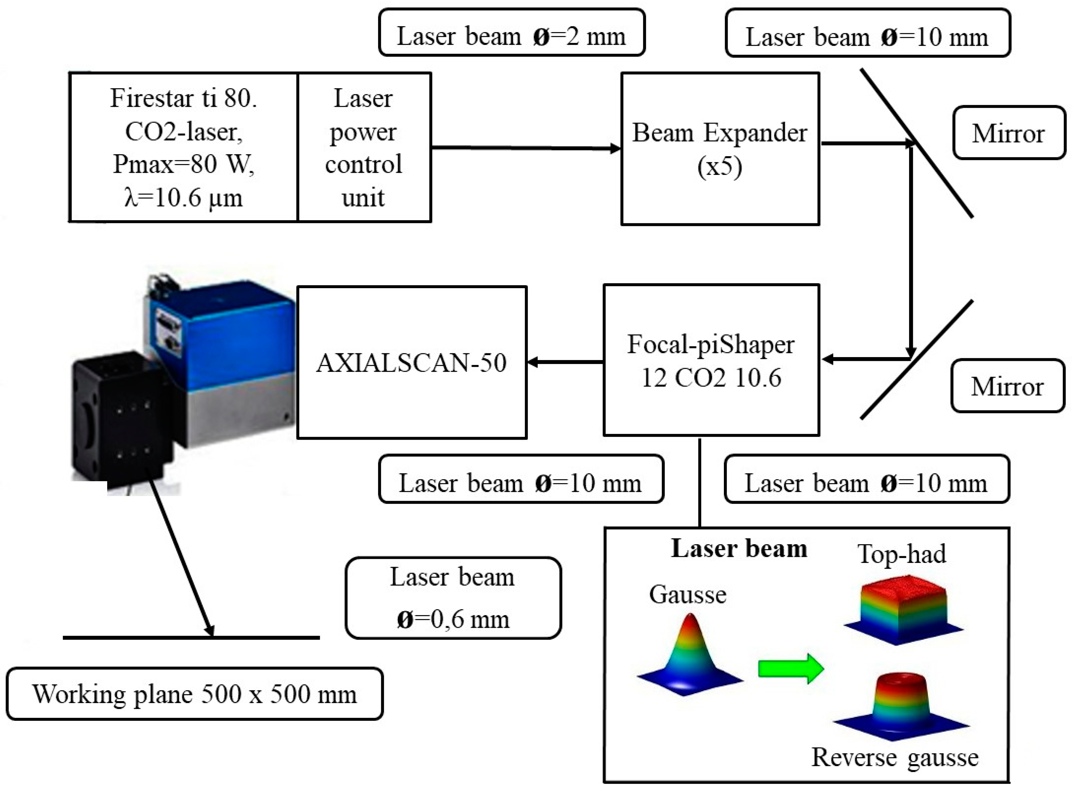
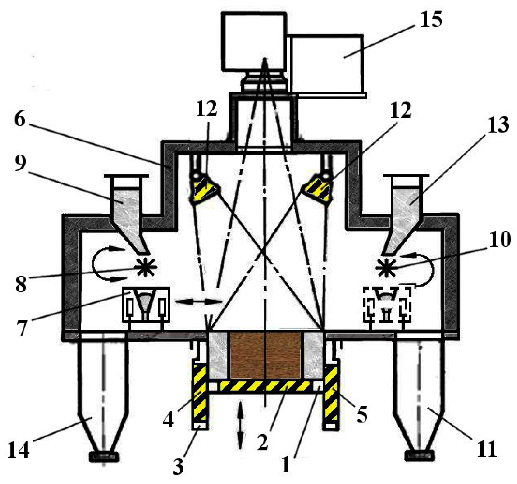
CO2—Firestar ti-Series 80 laser (Synrad, Mukilteo, WA, USA) [43]. This laser provides a power control range from 5 W to 80 W management to the frequency modulation of laser influence;
-
laser Beam Expander x5 (Synrad, Mukilteo, WA, USA) [44] is necessary for matching the optical characteristics between the scanner and the laser beam due to changing the intensity distribution device of laser radiation;
-
the intensity distribution device—Focal-piShaper-12 CO2 10.6 (Ald Optics, Berlin, Germany) [45]. This technical solution fundamentally distinguishes the laser-optical node developed by us, from other manufacturers of the SLS equipment. The Focal-piShaper device allows changing the laser intensity distribution from “gauss” to “reverse gauss” or “top hat” shape, which by some results [36,37,38], can improve the component’s quality produced by the SLS method;
-
the AXIALSCAN-50 scanner (Raylase, Wessling, Germany) [46]. A striking feature of this scanner is the constant diameter of the focused laser beam along the entire large 500 × 500 mm field of scanning. It is maintained due to the joint interaction of the fixed focusing lens and the rapidly moving defocusing lens. This technical solution is fundamentally different from the classical use of a dual-axis scanner with an f-theta objective in the SLS equipment;
-
two CO2 mirrors are necessary to turn the direction of laser beam propagation by 180° in order to achieve the maximum compactness of the laser scanning system.
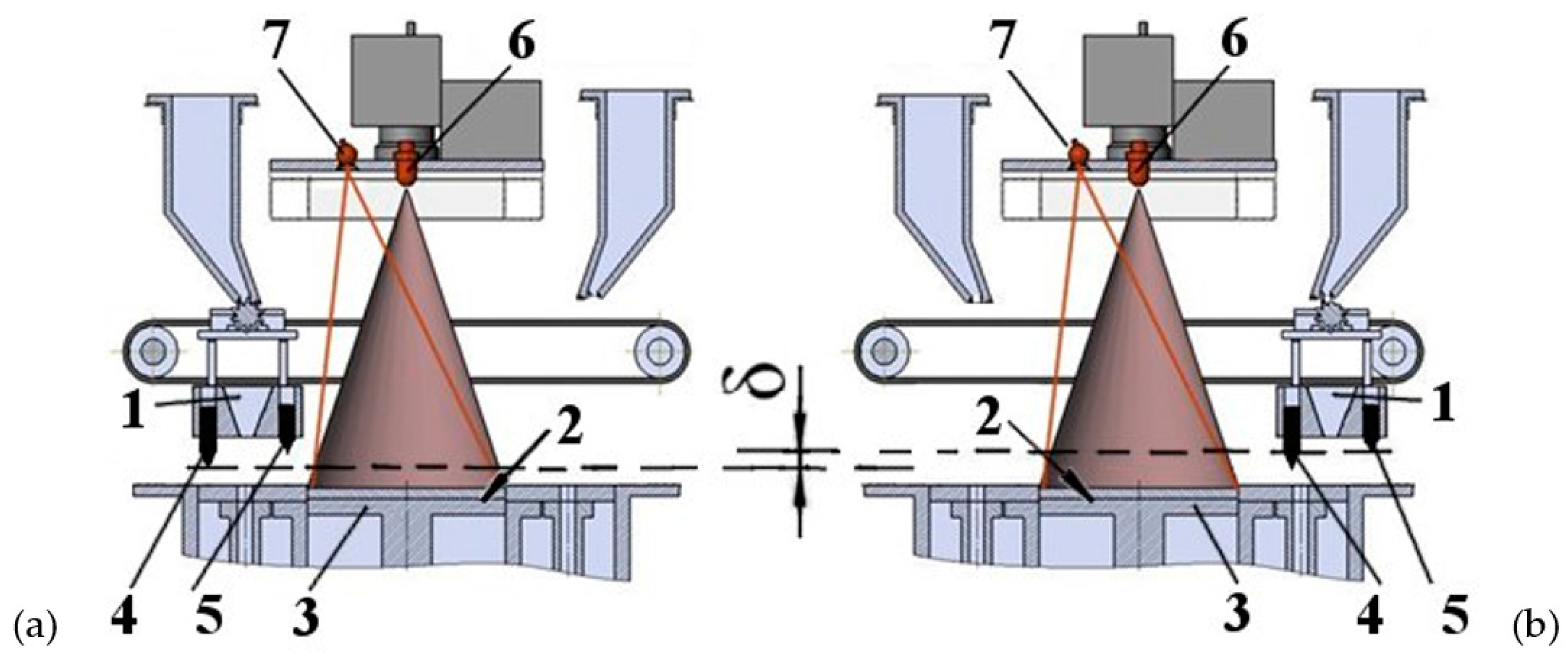
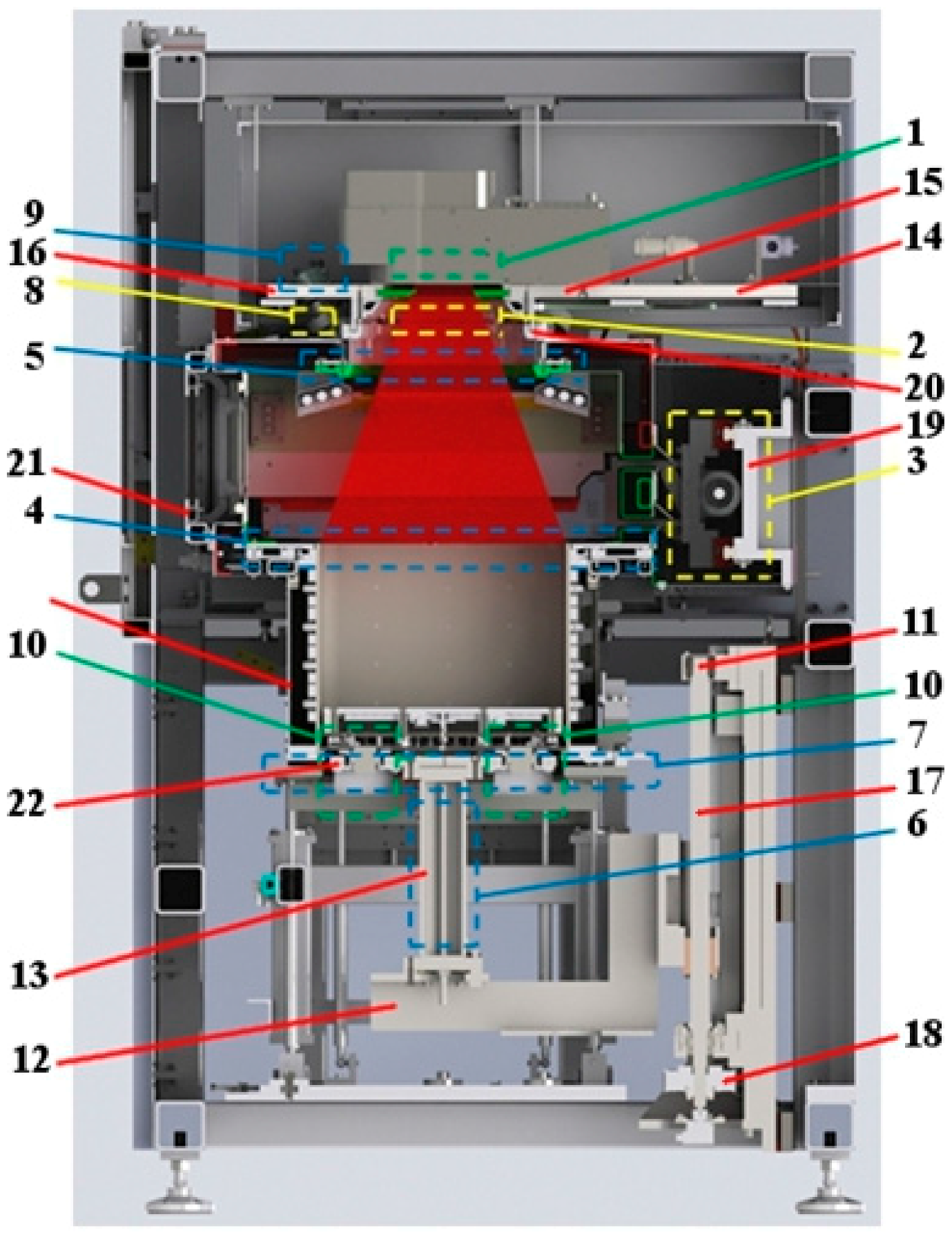
The correct thickness of each powder layer of ±10 μm applied over the whole 500 × 500 mm area under considerable and variable heating up to 385 °C much depends on the correct high-precision alignment of the recoater relative to the platform on which the layers are applied. Until recently, the correct recoater alignment was carried out manually by the operator before starting the sintering process. Then, the process of the part manufacturing was carried out in the automatic regime without further recoater control. In the case of improper initial alignment and/or subsequent recoater deflection, layers of various thicknesses appear. This can cause quality loss or manufactured part failure. The designed SLS machine is equipped with the automated recoater alignment control system based on the integral thermal pattern evaluation of the applied powder layer. Functioning of this monitoring system is based on the following principles (Figure 7):
(a)
leveling of the double-knife recoater is set by the operator manually before starting the operation on the upper surface of the platform;
(b)
leveling of the double-knife recoater is always skewed relative to the platform top surface. While applying the powder layer from the left limit position (Figure 7a), the applied layer thickness is specified by knife 4;
(c)
while applying the powder layer from the right limit position (Figure 7b), the thickness of the applied layer is specified by knife 5, and therefore the difference of the thickness of the layers applied from the left limit position and the right limit position will be δ μm;
(d)
in case of proper adjustment of the heaters installed above the applied powder layer, they transfer an equal heat amount to each applied powder layer;
(e)
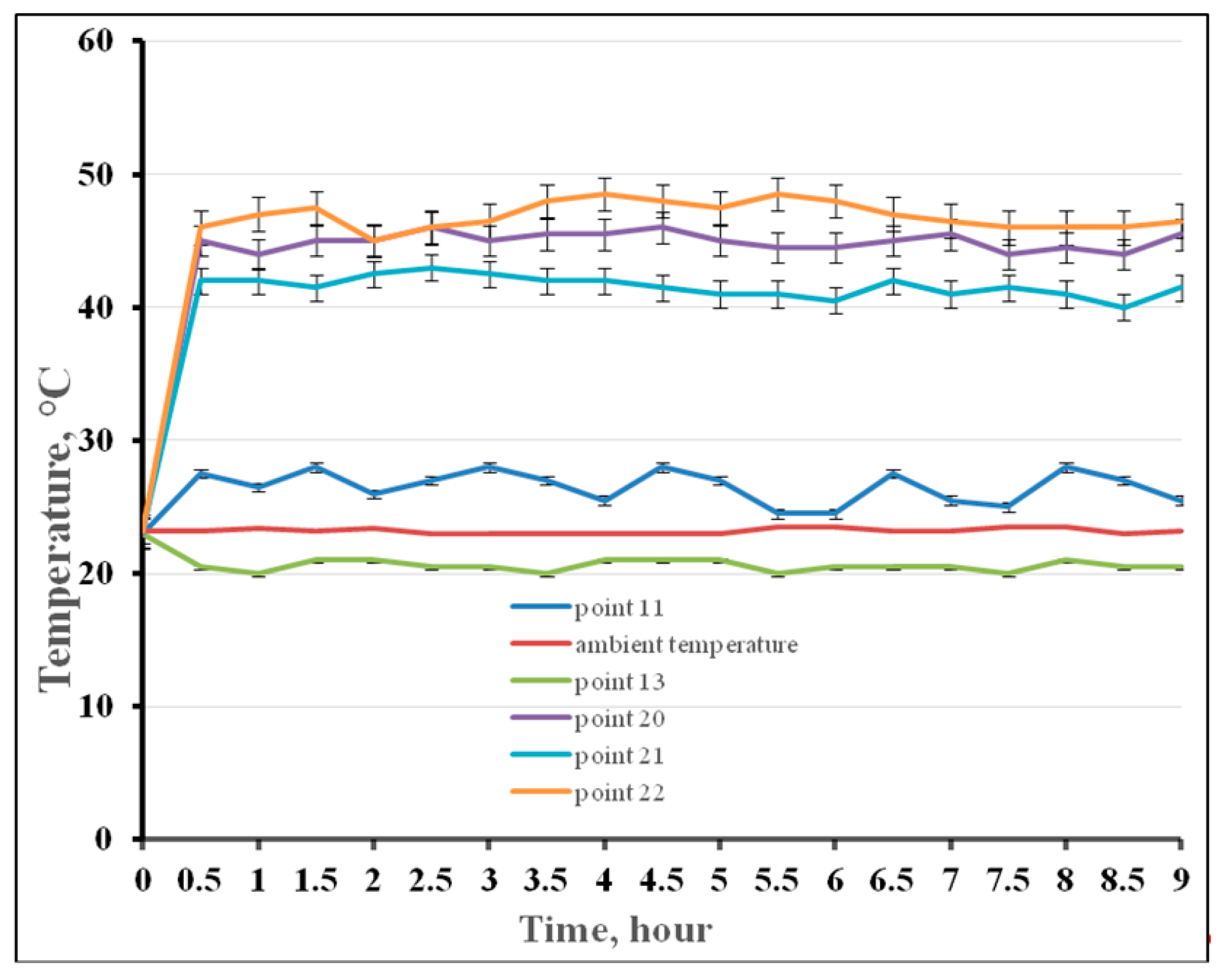
pyrometer mounted above the applied powder layer measures the heating of the applied powder layer and registers slight differences between the values of heating the powder layers applied from the left limit position and those applied from the right limit position due to the difference of thickness layers of the δ ~ 20 μm;
(f)
the sum of the heating values (integral heating) for the 25 layers of powder applied from the leftmost position will differ from the sum of the heat values for the 25 layers of powder deposited from the extreme right position due to the difference in layer thickness by the δ value;
(g)
Based on the difference in the integral heating for the powder layers applied from the extreme left and rightmost positions, the skewing degree of the leveling double knife relative to the upper surface of the platform can be unambiguously concluded;
(h)
the alignment control of the double knife according to the principles described above must be carried out before the 3D part building for the correctness verification of the operator adjustment, and also directly during the construction process.
The above-described principles allow controlling the powder delivery alignment device in the developed SLS machine in the automatic regime. We still have questions that remain unresolved: the duration and frequency of the heater’s switching on; and the summation sequence for the integral heating and allowance for possible skewing at the platform edges. Beyond this paper, there are remaining questions in relation to determining the technological regimes of the SLS process for the selected PEEK, which will be decided during the commissioning stage.

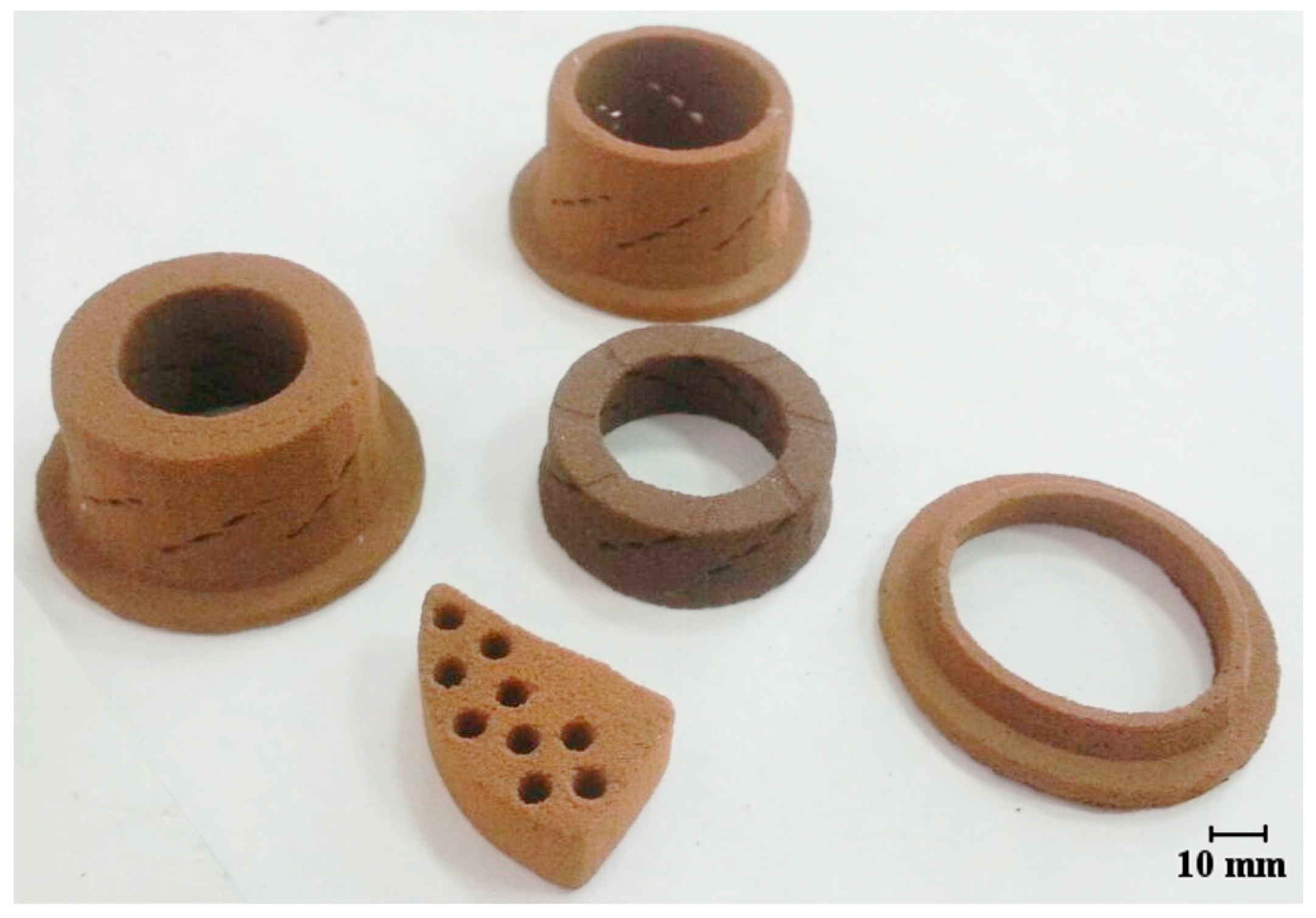
6. Experimental Implementation and Discussion

During the startup-setup operations, experiments on the inclusion of heaters built into the working table—6 (Figure 3) and heaters built into the replaceable hopper—25 to a temperature of 360 °C were conducted to measure how fast the stable heated state of the installation is being established. The temperature readings were taken from the thermocouples 38 (see Figure 3 and Figure 8) and in the specially installed points 101–108 for additional thermocouples (Figure 8). The observation points, which were specially installed thermocouples, started with the number 101. It was found that temperature fluctuations in thermocouples 38 (Figure 3 and Figure 8) do not exceed ±5 °C. These fluctuations can be considered as a “stable heated state of the installation” and are achieved in no more than 25 min. However, temperature variations that do not exceed ±5 °C in thermocouples established at points 101–108 (Figure 8) are achieved in a longer time, about 90–120 min (depending on the heating rate setting and ambient temperature). Based on this, we recommend accepting a time of about two hours for the stable heated state for the setup.
The correctness of the design, execution, and functioning of the cooling circuits set was confirmed by us experimentally. In particular, at points 11–22 (Figure 5), the temperature was controlled repeatedly during the commissioning work with a manual pyrometer for metals (the pyrometer accuracy is ±1 °C).
Figure 9 shows the time course of temperature changes at mentioned points. Temperature dependence testifies to the operation reliability of all the protective cooling circuits during the SLS process of the designed unit. As it follows from Figure 9, pyrometric control showed that in points 11–19, the heating temperature does not exceed the ambient temperature by more than 5 °C. At points 20–22 during the unit operation, the temperature ranges from 40 to 50 °C, which does not exceed the permissible values. In the point 13 setup was water cooled by means of a chiller set (~20 °C) and therefore it had a temperature below that of the environment. Figure 10 shows the appearance of the unit which we designed and assembled.
The correctness of the installation design is indirectly confirmed by the movement accuracy measured in node 4 (lower transition table, Figure 3 and Figure 8), which determines the vertical movement accuracy of node 5 (the building platform) through the system of rigid clamps. Measurements of the vertical displacement in node 4 were carried out under stabilized heating of the installation using a laser interferometer XL-80 (Renishaw, Wotton-under-Edge, UK, accuracy ±0.5 ppm [47]). After node 1 setting (lower transition table vertical drive, Figure 3) by means of a program correction application, node 4 repeatability was ±8μm. The moving accuracy of node 4 was ±5 μm. The given values of the fourth node displacement accuracy with the recoater correct operation ensure the uniform powder layers are delivered over the entire working area of 500 × 500 mm with a thickness of 120 ± 10 μm.
The developed installation has its own software open to modernization and enhancement, with the ability to manage a large set of technological and control parameters (the LI scan velocity and power, hatch distance, layer thickness, scanning strategy type, delay times on scanner mirrors, heater operation regimes, and speed moving drives, etc.). This is very important for carrying out an experimental study of searching for optimal technological regimes.
Installation operability and correctness of the adopted technical solutions are confirmed by the manufactured test samples shown in Figure 11. In Figure 11, the 3D test samples synthesized by us are shown; they have complex forms of various air nozzles with cooling channels. The material of the 3D samples was PEEK, courtesy of the manufacturer (Kabardino-Balkarian State University [48,49]). The next technological regime was used for the successful fabrication of parts (Figure 11): the platform heaters and the walls of the changeable frame are set to a temperature of 360 °C; the layer is preheated up to 385 °C; after 2 s, laser sintering begins (with upper heaters being cooled); CO2 laser radiation power was 12 W; the laser beam diameter was 300 μm; the scanning speed was 200 mm/s; the thickness of the delivered layer of the powder was 120 μm; and the hatching step was 250 μm. The laser scanning strategy in the single layer was organized by the following route. First, we outlined the outer contours, and then the inner part of the sample’s cross-section was hatched, usually with parallel lines, but sometimes with overlapping ones. On the next layer, everything was repeated, with a clockwise 45 degrees turn relative to the previous layer. The temperature control in the laser sintering zone can be realized as described earlier in [50]. Table 1 shows the comparative results of the mechanical properties of the obtained 3D samples and properties, and the samples claimed by the EOS [51].
It can be seen from Table 1 that the 3D part properties manufactured by the EOS company are higher, which is due to the study incompleteness of our approach. However, the high mechanical characteristics of the obtained 3D parts (the second column of Table 1) indicate the correctness of the technical solutions discussed and received in our presented installation. The search for optimal technological regimes that provide improved physical and mechanical properties of 3D parts from various high-temperature polymers has not yet been completed.

7. Conclusions

In this paper, for the first time in open access, we present the original design of SLS equipment for high-temperature polymers with an alignment controlling system for depositing powder layers. The kinematic and laser-optical schemes of the installation are discussed. It is shown that for successful realization of the SLS process for high-temperature polymers, it is necessary to achieve multi-circuit heating systems and to protect all the exact elements and devices of the setup from thermal effects at the same time. The types of protective cooling circuits are described, and the operation principles of the alignment control system for the powder layer delivering are disclosed. It has been shown that the distortion degree can be determined in an automatic regime for the powder layer device, and by comparison, the integral heating for the powder layers applied from the extreme left and rightmost positions. The operation capacity of the designed unit with the PEEK polymer was shown. The test 3D parts were successfully synthesized. The presented results of comparative tests of physical and mechanical properties of the manufactured parts showed their good quality.
The solutions offered by us expand the business and industry opportunities involved in the development of science-intensive production from high-temperature PEEK polymers.

Acknowledgments

The study was conducted within the frameworks of government contract N14.Z56.17.21.49-MK from 22 February 2017.

Author Contributions

A.N. conceived and designed the installation, he performed the experiments and wrote parts 2–6. I.Sk. prepared Introduction Section and was translator. I.Sh. analyzed the results, formulated the conclusions, was translator and proofreader, took part in writing parts 1, 2, 6, 7.

Conflict of Interest

The authors declare no conflict of interest.

References

  1. Gibson, I.; Rosen, D.W.; Stucker, B. Additive Manufacturing Technologies: Rapid Prototyping to Direct Digital Manufacturing; Springer: New York, NY, USA, 2010. [Google Scholar]
  2. Rundle, G.A. Revolution in the Making: 3D Printing, Robots and the Future; Affirm Press: South Melbourne, Australia, 2014. [Google Scholar]
  3. Shishkovsky, I.V. Laser Synthesis of Functional Mesostructures and 3D Parts; Fizmatlit Publ.: Moscow, Russia, 2009. [Google Scholar]
  4. Nazarov, A.P. Perspective of rapid prototyping via selective laser sintering/melting method. Vestnik MGTU Stankin 2011, 4, 46–51. [Google Scholar]
  5. Tarasova, T.V.; Nazarov, A.P. Investigation of the processes of modification of the surface layer and the manufacture of three-dimensional engineering components through selective laser melting. Vestnik MGTU Stankin 2013, 2, 17–21. [Google Scholar]
  6. Kinstlinger, I.S.; Bastian, A.; Paulsen, S.J.; Hwang, D.H.; Ta, A.H.; Yalacki, D.R.; Schmidt, T.; Miller, J.S. Open-Source Selective Laser Sintering (OpenSLS) of Nylon and Biocompatible Polycaprolactone. PLoS ONE 2016, 11, e0147399. [Google Scholar] [CrossRef] [PubMed]
  7. Van Hooreweder, B.; Moens, D.; Boonen, R.; Kruth, J.-P.; Sas, P. On the difference in material structure and fatigue properties of nylon specimens produced by injection molding and selective laser sintering. Polym. Test. 2013, 32, 972–981. [Google Scholar] [CrossRef]
  8. Nelson, J.S.; Xue, S.; Barlow, J.W.; Beaman, J.J.; Marcus, H.L.; Bourell, D.L. Model of Selective Laser Sintering of Bisphenol-A Polycarbonate. Ind. Chem. Eng. Res. 1993, 32, 2305–2317. [Google Scholar] [CrossRef]
  9. Berzins, M.; Childs, T.H.C.; Ryder, G.R. The Selective Laser Sintering of Polycarbonate. CIRP Ann. 1996, 45, 187–190. [Google Scholar] [CrossRef]
  10. Ivanova, A.M.; Kotova, S.P.; Kupriyanov, N.L.; Petrov, A.L.; Tarasova, E.Y.; Shishkovskii, I.V. Physical characteristics of selective laser sintering of metal-polymer powder composites. Quantum Electron. 1998, 28, 420–425. [Google Scholar] [CrossRef]
  11. Shishkovskii, I.V.; Kupriyanov, N.L. Thermal fields in metal-polymer powder compositions during laser treatment. High Temp. 1997, 35, 710–714. [Google Scholar]
  12. Ho, H.C.H.; Cheung, W.L.; Gibson, I. Morphology and Properties of Selective Laser Sintered Bisphenol A Polycarbonate. Ind. Eng. Chem. Res. 2003, 42, 1850–1862. [Google Scholar] [CrossRef]
  13. Goodridge, R.D.; Tuck, C.J.; Hague, R.J.M. Laser sintering of polyamides and other polymers. Prog. Mater. Sci. 2012, 57, 229–267. [Google Scholar] [CrossRef]
  14. Franco, A.; Lanzetta, M.; Romoli, L. Experimental analysis of selective laser sintering of polyamide powders: An energy perspective. J. Clean. Prod. 2010, 18, 1722–1730. [Google Scholar] [CrossRef]
  15. Goodridge, R.D.; Hague, R.J.M.; Tuck, C.J. Effect of long-term aging on the tensile properties of a polyamide 12 laser sintering material. Polym. Test. 2010, 29, 483–493. [Google Scholar] [CrossRef]
  16. Shishkovsky, I.V.; Juravleva, I.N. Kinetics of polycarbonate distraction during laser-assisted sintering. Int. J. Adv. Manuf. Technol. 2014, 72, 193–199. [Google Scholar] [CrossRef]
  17. Shishkovsky, I.; Nagulin, K.; Sherbakov, V. Study of biocompatible nano oxide ceramics, interstitial in polymer matrix during laser-assisted sintering. Int. J. Adv. Manuf. Technol. 2015, 78, 449–455. [Google Scholar] [CrossRef]
  18. Goodridge, R.D.; Hague, R.J.M.; Tuck, C.J. An empirical study into laser sintering of ultra-high molecular weight polyethylene (UHMWPE). J. Mater. Process. Technol. 2010, 210, 72–80. [Google Scholar] [CrossRef]
  19. Laureto, J.J.; Dessiatoun, S.V.; Ohadi, M.M.; Pearce, J.M. Open Source Laser Polymer Welding System: Design and Characterization of Linear Low-Density Polyethylene Multilayer Welds. Machines 2016, 4, 14. [Google Scholar] [CrossRef]
  20. Tarasova, E.; Juravleva, I.; Shishkovsky, I.; Ruzhechko, R. Layering laser-assisted sintering of functional graded porous PZT ceramoplasts. Phase Transit. Multinatl. J. 2013, 86, 1121–1129. [Google Scholar] [CrossRef]
  21. Volyansky, I.; Shishkovsky, I. Laser assisted 3D printing of functional graded structures from polymer covered nanocomposites. In New Trends in 3D Printing; Shishkovsky, I.V., Ed.; InTech Publ.: Rijeka, Croatia, 2016; Chapter 11; 268p. [Google Scholar]
  22. Serra, T.; Planell, J.A.; Navarro, M. High-resolution PLA-based composite scaffolds via 3-D printing technology. Acta Biomater. 2013, 9, 5521–5530. [Google Scholar] [CrossRef] [PubMed]
  23. Chia, H.N.; Wu, B.M. Recent advances in 3D printing of biomaterials. J. Biol. Eng. 2015, 9, 4. [Google Scholar] [CrossRef] [PubMed]
  24. Trachtenberg, J.E.; Mountziaris, P.M.; Miller, J.S.; Wettergreen, M.; Kasper, F.K.; Mikos, A.G. Open-source three-dimensional printing of biodegradable polymer scaffolds for tissue engineering. J. Biomed. Mater. Res. Part A 2014, 102, 4326–4335. [Google Scholar] [CrossRef]
  25. Laureto, J.; Tomasi, J.; King, J.A.; Pearce, J.M. Thermal properties of 3-D printed polylactic acid-metal composites. Prog. Addit. Manuf. 2017, 2, 57–71. [Google Scholar] [CrossRef]
  26. Wittbrodt, B.; Pearce, J.M. The effects of PLA color on material properties of 3-D printed components. Addit. Manuf. 2015, 8, 110–116. [Google Scholar] [CrossRef]
  27. EOS Plastic Materials for Additive Manufacturing. Available online: https://www.eos.info/material-p (accessed on 10 January 2018).
  28. Polyether Ether Ketone. Available online: https://en.wikipedia.org/wiki/Polyether_ether_ketone (accessed on 10 January 2018).
  29. VICTREX™ PEEK Polymers. Available online: https://www.victrex.com/~/media/datasheets/victrex_tds_450g.ashx (accessed on 10 January 2018).
  30. Berretta, S.; Evans, K.E.; Ghita, O. Processability of PEEK, a new polymer for High-Temperature Laser Sintering (HT-LS). Eur. Polym. J. 2015, 68, 243–266. [Google Scholar] [CrossRef] [Green Version]
  31. Schmidt, M.; Pohle, D.; Rechtenwald, T. Selective Laser Sintering of PEEK. CIRP Ann. Manuf. Technol. 2007, 56, 205–208. [Google Scholar] [CrossRef]
  32. PEEK (Polyarylethe-Retherketone). Available online: http://www.bpf.co.uk/plastipedia/polymers/peek.aspx (accessed on 10 January 2018).
  33. EOS Systems and Equipment for Plastic Additive Manufacturing. Available online: https://www.eos.info/systems_solutions/plastic/systems_equipment (accessed on 10 January 2018).
  34. D Systems. Available online: https://www.3dsystems.com/3d-printers/plastic#selective-laser-sintering-printers-sls (accessed on 10 January 2018).
  35. EOS P 500—The Automation-Ready Manufacturing Platform for Laser Sintering of Plastic Parts on an Industrial Scale. Available online: https://www.eos.info/systems_solutions/eos-p-500 (accessed on 17 January 2018).
  36. Zhirnov, I.; Podrabinnik, P.; Okunkova, A.; Gusarov, V. Laser beam profiling: Experimental study of its influence on single-track formation by selective laser melting. Mech. Ind. 2015, 16, 709. [Google Scholar] [CrossRef]
  37. Gusarov, V.; Okunkova, A.; Peretyagin, P.; Zhirnov, I.; Podrabinnik, P. Means of Optical Diagnostics of Selective Laser Melting with Non-Gaussian Beams. Meas. Tech. 2015, 58, 872–877. [Google Scholar] [CrossRef]
  38. πShaper. Available online: http://www.pishaper.com/public.php (accessed on 10 January 2018).
  39. HEATRODSHOP. Available online: http://www.heatrodshop.com/product/qhs (accessed on 10 January 2018).
  40. Mir Nagreva. Available online: https://www.mirnagreva.ru/catalog/infrakrasnye_nagrevateli_obogrevateli_lampy/kvartsevye_nagrevateli/kvartsevye_galogenovye_izluchateli/ (accessed on 10 January 2018).
  41. Thermon. Available online: http://www.thermon.co.za/catalogue/heating-elements/flat-elements-box-heaters/thermon-fc-flat-heater-ceramic-insulation (accessed on 10 January 2018).
  42. Marion. Available online: http://elektroteni.ru/ploskie.html (accessed on 10 January 2018).
  43. Synrad. Available online: https://www.synrad.com/synrad/docroot/products/lasers/ti-series (accessed on 10 January 2018).
  44. Synrad. Available online: https://www.synrad.com/synrad/docroot/products/accessories/beam-expanders (accessed on 10 January 2018).
  45. πShaper. Available online: http://www.pishaper.com/shaper_for_co2.php (accessed on 10 January 2018).
  46. Raylase. Available online: https://www.raylase.de/en/products/3-axis-deflection-units/axialscan-50.html (accessed on 10 January 2018).
  47. Renishaw. Available online: http://www.renishaw.com/en/xl-80-laser-system--8268 (accessed on 30 January 2018).
  48. Shakhmurzova, K.T.; Kurdanova, Z.I.; Khashirova, S.Y.; Beev, A.A.; Ligidov, M.K.; Pahomov, S.I.; Mikitaev, A.K. Polyetherketones. Receiving, properties and application. News Higher Educ. Inst. Chem. Eng. Chem. 2015, 58, 3–11. [Google Scholar]
  49. Shakhmurzova, K.T.; Kurdanova, Z.I.; Jansitov, A.A.; Baikaziev, A.E.; Hashitova, S.U.; Pahomov, S.I.; Ligidov, M.K. Synthesis and Properties of Aromatic Polyester Resins with Cord Fragments. News Higher Educ. Inst. Chem. Eng. Chem. 2017, 60, 28–39. [Google Scholar] [CrossRef]
  50. Shishkovsky, I.V.; Morozov, Y.G.; Kuznetsov, M.V.; Parkin, I.P. Surface laser sintering of exothermic powder compositions: A thermal and SEM/EDX study. J. Therm. Anal. Calorimetery 2008, 92, 427–436. [Google Scholar] [CrossRef]
  51. Hasenauer-Hesse. Available online: http://www.hasenauer-hesser.de/fileadmin/dokumente_infos/datebblaetter/en/EOSPeek.pdf (accessed on 30 January 2018).
Figure 1. Schematic view of the SLS machine for manufacturing parts made of the PEEK powder: 1—platform, 2—heater, 3—changeable frame, 4 and 5—heaters, 6—airtight chamber, 7—double-knife recoater, 8—splined shaft, 9—powder delivery hopper, 10—splined shaft, 11—powder collection hopper, 12—top heaters, 13—powder delivery hopper, 14—powder collection hopper, and 15—laser-optical unit.
Machines 06 00011 g001
Figure 2. General view of the SLS machine (the outer panels are conditionally shown as transparent). Dimensions 2470 × 1570 × 2480 mm (length × width × height).
Machines 06 00011 g002
Figure 3. Structural plan (described in the text). Zone A is highlighted in further detail in below Figure 8: (a)—longitudinal section, (b)—cross-section.
Machines 06 00011 g003
Figure 4. Kinematic scheme of the SLS machine: M1, M2, M3, M4—electric motors; X, Y—axes of the main movements; Z, X1, B, B1, X2—axes of auxiliary movements; SQ1, SQ2, SQ3, SQ4—endpoint sensors; BQ1, BQ2, BQ3, BQ4—position control sensors.
Machines 06 00011 g004
Figure 5. Cooling circuits of the SLS machine (cross-section of the Figure 3b). Different indicator colors correspond to the selected cooling circuit: water—blue, nitrogen—yellow, air—green, control points—red color.
Machines 06 00011 g005
Figure 6. The laser-optical scheme of the SLS machine.
Machines 06 00011 g006
Figure 7. Schematic drawing of the recoater alignment control system of the SLS machine: (a) application of powder layer from the left limit position, (b) application of powder layer from the right limit position. Designation of numbers: 1—double-knife recoater; 2—upper surface of the platform; 3—platform; 4—left knife; 5—right knife; 6—top heaters; 7—pyrometer.
Machines 06 00011 g007
Figure 8. Details of the “Zone A” area from Figure 3a: points (101–108) are the locations of specially installed thermocouples for the experiment, points 38 are stationary thermocouples of the installation (repeat position with Figure 3a), 4—lower transition table, 5—building platform (repeat position with Figure 3a).
Machines 06 00011 g008
Figure 9. Dependence between the temperature in control points 11–22, and the work time of the installation.
Machines 06 00011 g009
Figure 10. The created installation with the removed protective covers and nodes for access to points 11–22 from Figure 5 in order to maintain temperature control.
Machines 06 00011 g010
Figure 11. Produced test 3D parts from the PEEK.
Machines 06 00011 g011
Table 1. Comparison of mechanical properties.
Name of ItemManufactured Samples EOS Data [51]
Tensile modulus ASTM D6383150 ± 150 MPa4250 ± 150 MPa
Tensile strength ASTM D63870 ± 8 MPa90 ± 5 MPa
Elongation at break ASTM D6382.5 ± 0.2%2.8 ± 0.2%

