
Optimization of Sweep and Blade Lean for Diffuser to Suppress Hub Corner Vortex in Multistage Pump

1
National Research Center of Pumps, Jiangsu University, Zhenjiang 212013, China
2
Department of Fluid Machinery and Engineering, Xi’an Jiaotong University, Xi’an 710049, China
*
Author to whom correspondence should be addressed.
Machines 2021, 9(12), 316; https://doi.org/10.3390/machines9120316
Submission received: 27 October 2021
/
Revised: 17 November 2021
/
Accepted: 25 November 2021
/
Published: 26 November 2021
(This article belongs to the Special Issue Optimization and Flow Characteristics in Advanced Fluid Machinery)
Abstract
:The bowl diffuser is the main flow component in multistage submersible pumps; however, secondary flow fields can easily induce a separation vortex in the hub corner region of the bowl diffuser during normal operation. To explore the flow mechanism of the hub corner separation vortex and develop a method for suppressing hub corner separation vortices, the lean and sweep of the diffuser blade were optimized using computational fluid dynamics (CFD) simulations and central composite design. Diffuser efficiency, static pressure recovery coefficient, and non-uniformity were selected as the optimization objectives. Details of the internal flow were revealed and the collaborative response relationships between blade lean/sweep parameter equations and optimization objectives were established. The optimization results show that a greater pressure difference between the pressure surface and suction surface (PS–SS) at the inlet can offset transverse secondary flow, whereas a lower PS–SS pressure difference will cause a drop in low-energy fluid in the diffuser mid-section. The blade’s lean scheme suppresses the hub corner separation vortex, leading to an increase in pressure recovery and diffuser efficiency. Moreover, optimizing the sweep scheme can reduce the shroud–hub pressure difference at the inlet to offset spanwise secondary flow and enhance the hub–shroud pressure difference at the outlet, thus driving low-energy fluid further downstream. The sweep scheme suppresses the hub corner vortex, with a resulting drop in non-uniformity of 13.1%. Therefore, optimization of the diffuser blade’s lean and sweep can result in less low-energy fluid or drive it further away from hub, thereby suppressing the hub corner vortex and improving hydraulic performance. The outcomes of this work are relevant to the advanced design of bowl diffusers for multistage submersible pumps.
1. Introduction
The multi-stage submersible pump is widely used in various fields, mainly owing to its strong adaptability and easy pressurization [1]. However, complex and changeable working conditions present strict requirements for operational stability. The impeller and bowl diffuser are the main components in each stage of the pump. The head can be adjusted by changing the stage of the pump to meet the requirements of different applications. However, multi-stage submersible pumps with a bowl diffuser typically suffer from low efficiency and high operating costs. The bowl diffuser flow channel is curved and the fluid has a large impact on the inlet. Moreover, pump losses are dominated by the separation vortex in the hub corner of the diffuser. Therefore, optimization of the bowl diffuser is crucial to improving the single-stage head and overall working performance of the multistage submersible pump.
To date, numerous studies on the optimization of impellers and diffusers in pumps have been published [2,3]. To determine the algebraic relationship between the structural parameters of pumps and optimization objectives, data can be more efficiently and accurately analyzed using computational fluid dynamics (CFD) [4,5,6]. To obtain the optimal solution, CFD simulations are often combined with optimization design methods, such as the response surface method, neural network simulations, and orthogonal experiments [7,8,9]. Tong et al. [10] used numerical simulations and the Latin hypercube sampling method to construct functional relationships among independent variables and optimization objectives. Then, the second-generation genetic algorithm was used to solve the multi-objective optimization problem for a centrifugal pump. Stel et al. [11] studied the influence of pump stage on the performance of a multi-stage submersible pump using a CFD method based on the finite volume approach and investigated the transient flow characteristics in the pump under different flow rates. Heo et al. [12] compared three approximate models based on the response surface function (RSF), Kriging response surface, and a neural network for finding Pareto-optimal solutions which are set in the independent variable domain of the centrifugal pump.
The approximate model design method has been widely used in pump design [13,14]. Previous approaches could be applied to the optimization of other structural parameters, such as blade inlet and outlet angle, blade number, and blade thickness. Nonetheless, optimization techniques to achieve an optimal diffuser design that maximizes performance and stability of the overall stage are still lacking. Recently, design optimization strategies have been widely applied in the field of pneumatic fluid machinery, including the design of blade lean and sweep. A brief review is presented herein.
Rosic et al. [15] analyzed the influence of the stationary blade stacking combination on turbine performance. Razavi et al. [16] designed transonic rotor blades with different degrees of sweep and tilt. The blades were optimized using a neural network-based multi-objective optimization method, with efficiency, operating range, and stage pressure ratio as the target variables. He et al. [17,18] studied the influence of blade sweep design on transonic impeller performance through numerical simulations. The results showed that a forward-swept shroud design reduces the forward load, impact strength, and leakage vortex. A back-swept hub design suppresses the blade front load and the separation of secondary flow, thereby reducing losses near the hub. Bagshaw et al. [19] designed specially shaped cascade end walls with reverse load tilting, which can effectively inhibit the development of secondary flow in cascades. Goto et al. [20,21] used the color oil film flow display technology to capture large-scale separation vortices in the suction surface corner region of the diffuser and showed that the flow separation vortex is a source of hydraulic losses in the diffuser. Scillito et al. [22] used the large-eddy simulation method to confirm that axial compressor losses are dominated by the three-dimensional flow region near the diffuser end wall, two-dimensional laminar flow separation, and the diffuser outlet wake. The influence of inlet turbulence on sources of loss was further investigated.
In summary, blade lean and sweep design are widely used in compressor and turbine blades [23,24]; however, these approaches are rarely applied to water pumps, in particular, the bowl diffuser. The present study aimed to address these limitations by applying the design ideas and methods used for pneumatic machinery to the bowl diffuser of a multistage submersible pump. This research provides a scientific basis for follow-up research on diffuser design optimization.
The remainder of this paper is organized as follows. Section 2 describes the numerical model and simulation setup. Details of the experimental detection method are presented in Section 3. In Section 4, optimized designs of the blade lean and sweep of the bawl diffuser are presented based on the concept of parametric equations. In Section 5, the influence of various design schemes on the hydraulic characteristics of the diffuser are discussed and the collaborative response relationship between the parameter equation and the hydrodynamic performance of the diffuser is established. Section 6 discusses the effect of various optimization strategies on the hub corner separation vortex in the diffuser. Finally, the main conclusions of this work are summarized in Section 7.
2. Numerical Model and Simulation Setup
2.1. Computational Domain
In this paper, a Q80-20 multi-stage submersible pump with a bowl diffuser was selected as the research object. The basic parameters of the main flow passage parts of the multi-stage submersible pump are as follows: design flow rate, Q = 80 m³·h−1; single-stage head, H = 18 m; rotating speed, n = 2850 r/min. The main structural parameters of the impeller and the bowl diffuser are presented in Table 1 and Table 2. Geometric models of the impeller and bowl diffuser of the multistage submersible pump are shown in Figure 1.
According to Shi et al. [25], the internal flow characteristics in the second stage of the pump are basically the same as those in the later stages. Therefore, the following tests were based on data obtained from the second stage of the pump. To consider all stages, a large number of grid elements must be generated, which dramatically increases the calculation time. To balance computation time and numerical accuracy, Zhou et al. [26] demonstrated that two stages can be used to represent the whole pump system; therefore, the two-stage pump model was selected for the present work. The three-dimensional (3D) pump modeling software CFturbo was used to model the whole flow field of the pump, as shown in Figure 2. The calculation domain is mainly comprised of the inlet pipe, impeller, bowl diffuser, and outlet pipe. Each stage of the impeller and bowl diffuser constitutes a pressurization unit, and there are two pressurization units in total. To ensure fully developed fluid flow and improve the flow field calculation accuracy, the inlet pipe, outlet pipe, and outlet of the bowl diffuser were extended appropriately.
2.2. Mesh Generation
The ANSYS ICEM CFD software package was used to generate an unstructured mesh as the calculation domain. Key regions of the mesh were locally refined. Six grids of various sizes were selected to verify the grid independence of the calculation domain and ensure a grid quality greater than 0.3. As seen in Table 3, the simulation results become stable as the total number of grid elements increases. When the total number of elements is 6.8 million or higher, further changes in the calculated head and efficiency are very small, suggesting that the number of grid elements no longer has an effect on the calculation results. To balance computation time and solution accuracy, the total number of grid elements was selected as approximately 6.8 million. The generated mesh is shown in Figure 3.
2.3. Turbulent Model
The standard k-ε model is based on turbulent kinetic energy (k) transport and turbulent energy dissipation rate (ε) transport and offers good robustness and economy in predicting the flow characteristics of most flow fields reasonably and accurately. However, the standard k-ε model is prone to errors when calculating flow over a complex curved wall [27]. To account for the high-speed rotation domain and large variation in curvature of the wall in the calculation domain of the multi-stage submersible pump, the RNG k-ε model proposed by Yakhot et al. [28] was selected, which is suitable for flows with separation [29]. Compared with the standard k-ε model, the RNG k-ε model contains an additional time average strain rate (Eij) in the reaction mainstream equation of ε, which can improve the accuracy for swirl flow and more reasonably deal with flow near the wall [30,31]. The two transport equations can be expressed, as follows:
The turbulent kinetic energy k transport equation:
The turbulent energy dissipation rate ε equation is:
where k is turbulent kinetic energy, m²/s²; ε is turbulent energy dissipation rate, m²/s³; Pk is the pressure generating term caused by the velocity gradient; µt is the turbulent viscosity.
2.4. Simulation Setup
ANSYS CFX 17.1 was used to calculate the steady three-dimensional whole flow field of the model pump under the design conditions. The fluid in the pump was set as incompressible water. The RNG k-ε model was selected for the simulation calculations to satisfy the solution accuracy requirement. The boundary conditions were set, as follows: the inlet boundary condition was set as pressure inlet and the static pressure as 0 Pa; The outlet boundary condition was set to the mass flow outlet condition. The adiabatic nonslip solid wall boundary condition was adopted at the wall and the near wall area was treated as a scalable wall function.
The steady numerical calculation was carried out across the whole calculation domain of the multistage submersible pump. The impeller part was considered the rotating domain and the bowl diffuser part was considered the static domain. The interfaces between the rotating section and the static section were set as the dynamic and static interfaces, and the frozen rotor model was used to handle them. The General Grid Interface (GGI) was used as the grid connection method for dealing with the static interface. The root mean square (RMS) value for convergence accuracy was set to 5 × 10⁻⁵.
3. Experimental Pump Characteristics
To verify the simulation method, the head obtained using CFD was compared with experimental head values in the flow range of 0.8Qd–1.1Qd. The test-bed, shown in Figure 4, is composed of a flow control device, a data acquisition device, and a data processing device [32,33]. The flow rate was adjusted by the valve and measured by the electromagnetic flowmeter.
The comparison of head obtained by experiment and simulation was shown in Figure 5. The average error between the numerical simulation results and the experimental results was less than 5%, and the relative error of the head under the design conditions was 2.7%. Errors between the simulation results and experimental results were within the allowable range. The results indicate that the simulation calculation can accurately predict the performance of the multistage submersible pump under the design conditions.
4. Optimization Schemes
4.1. Design of Blade Lean
The coordinate system of the blade inlet profile was established, as shown in Figure 4. The origin of the coordinate system is defined as the intersection between the blade inlet edge and the hub. The positive direction of the ordinate axis is from the hub to the shroud of the diffuser, expressed by the spanwise coefficient Sp1. The circumferential direction is the positive direction of the abscissa, represented by f (Sp1). The starting angle of any point at the inlet edge of the blade refers to the angle between the line connecting the point to the center point and the axial plane with a starting angle of zero, indicated by θ in Figure 6.
It is assumed that the parabolic equation governing the blade inlet profile is:
where spanwise coefficient Sp1 ϵ [0,1], 0 for the hub and 1 for the shroud; a0, a1, and a2 are the parameters to be optimized. The difference between the starting angle of the hub and the shroud is referred to as the starting angle difference ∆θ, defined as
where θHub is the starting angle of the hub at the blade inlet, θHub = a0; θShroud is the starting angle of the shroud at the blade inlet, θShroud = a0 + a1 + a2, ∆θ = a1 + a2. The factors and the levels used in the central composite designs are presented in Table 4.
4.2. Design of Sweep
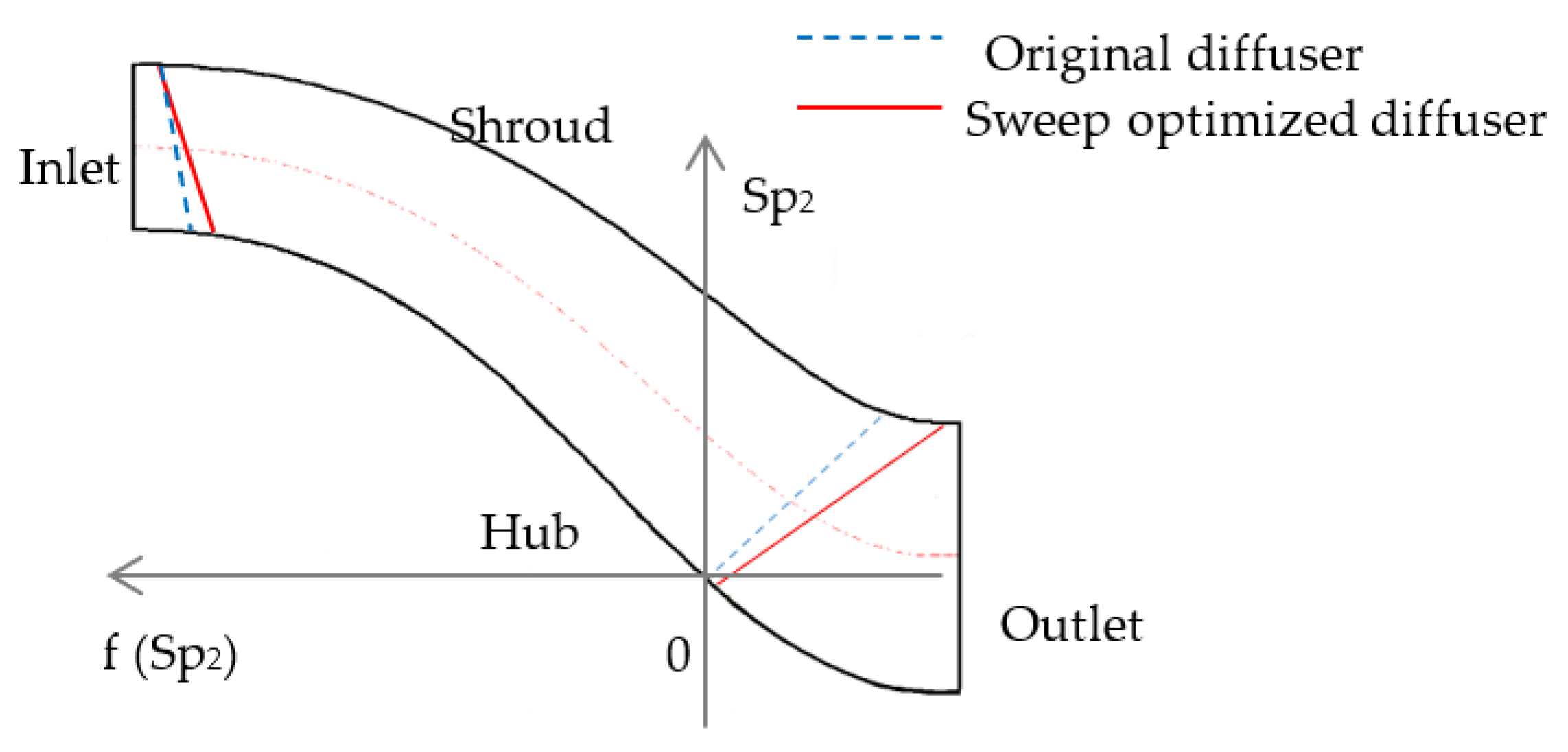
Figure 5 shows the sweep coordinate system in the meridian plane of the diffuser. The positive direction of the longitudinal axis is defined as the direction from the hub to the shroud, expressed by the spanwise coefficient Sp2. The axis is the positive direction of the abscissa, represented by f (Sp2). The origin is the intersection between the hub and the blade outlet edge. It is assumed that the parabolic equation governing the blade inlet profile is
where Sp2 is the spanwise coefficient; Sp1ϵ [0,1], 0 for hub and 1 for shroud.
As shown in Figure 7, b0 is located at the edge of the outlet on the hub, b1 is located at the edge of the outlet on the shroud, and b2 is located at the edge of the inlet on the hub, selected as the independent factors. The values are presented in Table 5. The sweep angle β is the angle between the new outlet edge of the blade and the original outlet edge of the blade. When the position of the blade outlet edge on the hub remains unchanged and the position of the shroud moves in the positive direction along the abscissa, β is negative; when moving in the negative direction along the abscissa, β is positive. Here, the positive and negative signs indicate direction only.
4.3. Analysis Parameters
Diffuser efficiency ɳ, static pressure recovery coefficient Cp, and non-uniformity ζi were selected to evaluate the hydrodynamic performance of the diffuser before and after optimization. The diffuser efficiency is . Pt3 is the total pressure at the inlet of the diffuser and Pt4 is the total pressure at the outlet of the diffuser. Static pressure recovery coefficient is , Ps3 is the static pressure at the inlet of the diffuser and Ps4 is the static pressure at the outlet of the diffuser. Cp indicates the potential for converting kinetic energy into static pressure energy as fluid flows through the diffuser. An increase in Cp indicates enhanced static pressure recovery ability.
The non-uniformity ζi is an index for quantitatively evaluating flow uniformity at the outlet of the diffuser. The efficiency and operating stability of the pump are inversely affected by flow uniformity in the diffuser and impeller. As flow uniformity increases at the outlet of the diffuser, ζi decreases; conversely, as the flow becomes less uniform, ζi increases. The formula for calculating the non-uniformity ζi is
where Q is the design flow rate; Vz is the local axial velocity in the flow section, m/s. Here, the section is the outlet surface of the diffuser and VF,av,i is the average velocity at the outlet surface of the diffuser, m/s.
5. Results
5.1. Response Surface of the Blade Lean Optimized Diffuser
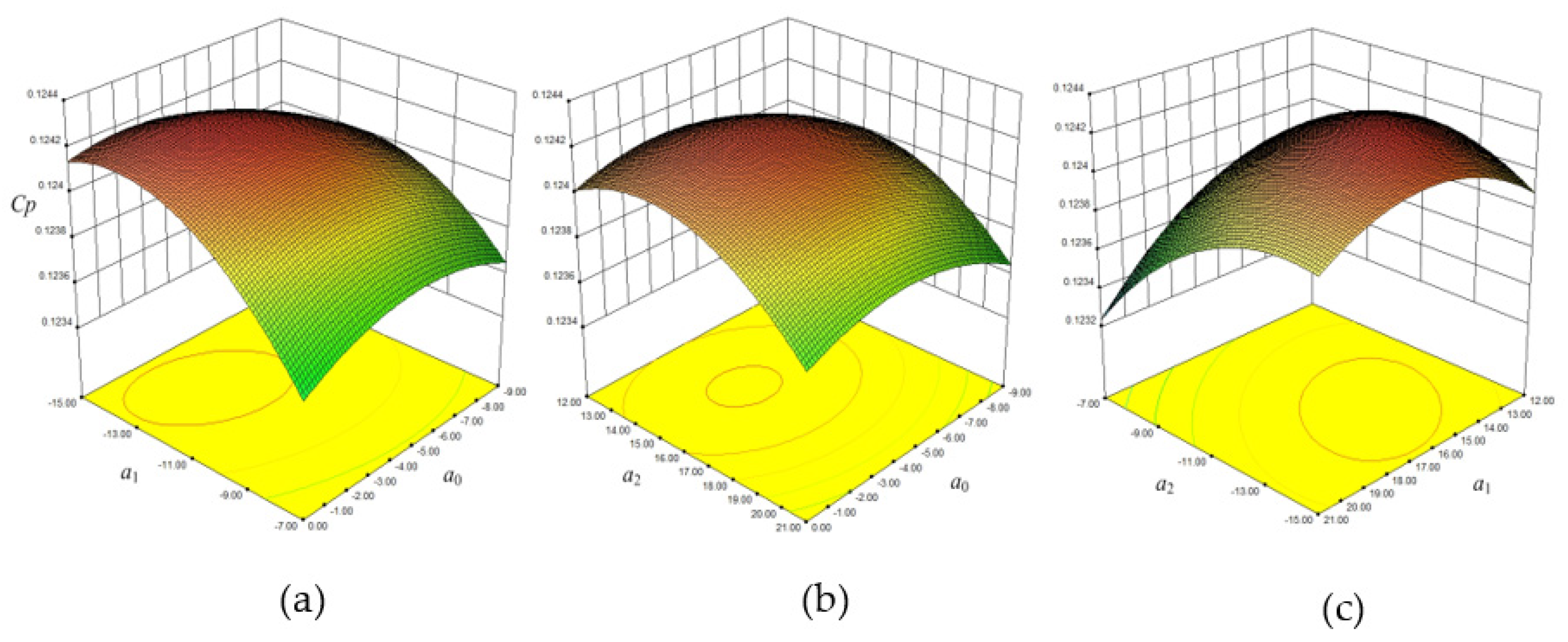
Factor a0 represents the starting angle of the blade on the hub surface, a1 is related to the position of the axis, and a2 affects the opening size of the parabola. The influence of pairs of factors on the response value was analyzed by fixing any one of the three factors a0, a1, and a2 to zero. Figure 8a,b show that the opening of the response surface is downward, and the trend is consistent when a2 is at a medium level or a1 is at a medium level. The radian of the curve increases when the starting angle on the hub surface is −4.5° (medium a0), the symmetrical axis moves to hub (high a1), and the opening of parabola decreases (high a2), which improves the diffuser efficiency. Figure 8c shows that the interaction between factors a1 and a2 is significant when a0 is medium. The interaction between a1 and a2 results in optimal diffuser efficiency when both a1 and a2 are high.
Figure 9a shows that the static pressure recovery coefficient reaches the optimal value when a0 is above the medium level and a1 is at the medium level on the low side. A medium–high level of a0 indicates that the starting angle of the hub at the blade inlet θ ϵ (0°, 4.5°). A medium–low level of a1 indicates that the symmetrical axis of the curve deviates from the shroud, therefore, movement of the symmetrical axial can improve the conversion rate of kinetic energy to static pressure in the diffuser. Figure 9b shows that the static pressure recovery coefficient is optimal when a0 is medium level and a2 is medium–low level. A medium level of a0 results in a starting angle of the inlet edge on the hub of 4.5° and when a2 is medium–low, the curve of the inlet edge changes gently as the static pressure recovery coefficient increases. Figure 9c shows that the static pressure recovery coefficient reaches the optimal value when a1 is at a medium–low level and a2 is at a medium level. A medium–low level of a1 indicates that the symmetry axis of the curve is inclined towards the shroud and a medium level of a2 indicates that the opening size and bending size of the curve are moderate. Therefore, the static pressure recovery coefficient of the diffuser will decrease if the inlet edge bends excessively or too gently. Importantly, the static pressure recovery coefficient is improved when the inlet profile is moderately bent with an axially symmetrical offset to the shroud.
Figure 10 shows the response surface with non-uniformity. Figure 10a shows that low levels of a0 and a1 minimize non-uniformity. When a0 is low, the starting angle of the inlet edge of the diffuser on the hub is 9°. When a1 is low, the axis of the curve moves from the hub side to the center of the spanwise end, the internal flow uniformity of the diffuser improves, and non-uniformity decreases. Figure 10b shows that when a0 and a2 are both at low levels, non-uniformity is lowest. When a1 is at a medium level, the contour lines of the diffuser non-uniformity are evenly distributed, and the variation of the response surface is relatively gentle. The non-uniformity decreases with decreasing a2 but is less affected by a0. Figure 10c shows that both a2 and a1 have the lowest non-uniformity at low levels. When the starting angle on the hub of the inlet side is large, the symmetrical axis of the inlet profile is at 1/2 of the spanwise direction and the range of starting angles for each flow surface in the spanwise direction increases. Thus, the internal flow characteristics and flow uniformity in the diffuser can be improved.
The factor a2 has the largest influence on the diffuser efficiency, followed by a1, and the influence of a0 is the smallest. The diffuser efficiency increases with the increase of a1 and a2, increasing first and then decreasing with the increase of a0. The influence of factor a1 on the static pressure recovery coefficient of diffuser is the largest, followed by a2, and a0 is the smallest. The static pressure recovery coefficient increases first and then decreases with the decrease of the three factors. Moreover, a1 and a2 have significant effects on the diffuser non-uniformity, while a0 has little effect on the non-uniformity. When the three factors are at a low level, the non-uniformity is the lowest, and the outlet uniformity of the diffuser is the best. The optimal blade lean scheme was obtained by considering the actual operating conditions of the multi-stage submersible pump and the effects of a0, a1, and a2 on diffuser efficiency, static pressure recovery coefficient, and non-uniformity, as shown in Table 6. The results show that when a0 is at the medium level of −4.4, a1 has the low level of –12 and a2 has the medium level of 15.16 both the diffuser efficiency and the static pressure recovery coefficient improve.
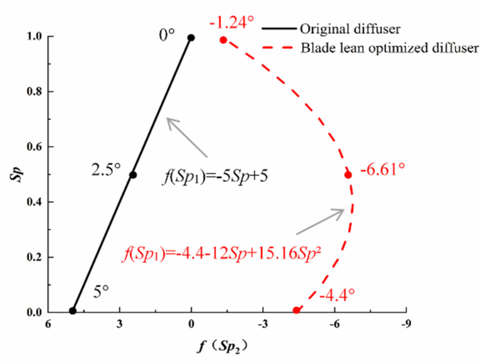
Structural changes to the inlet edge of the blade lean optimized diffuser and the original diffuser are shown in Figure 11. The inlet edge profile equation and spanwise distribution of the initial angle are illustrated in Figure 12. The starting angle of the blade lean optimized diffuser has a curved distribution, and the starting angle of the original diffuser has a linear distribution. After optimization, the governing equation of the blade inlet profile is f (Sp1) = −4.4−12Sp + 15.16Sp², with axis Sp = 0.4. The starting angle of the hub is −4.4° and the starting angle of the shroud is −1.24°. The efficiency of the optimized diffuser is 0.32% higher than that of the original diffuser, and the static pressure recovery coefficient is 2.64% higher. However, the non-uniformity is 9% lower.
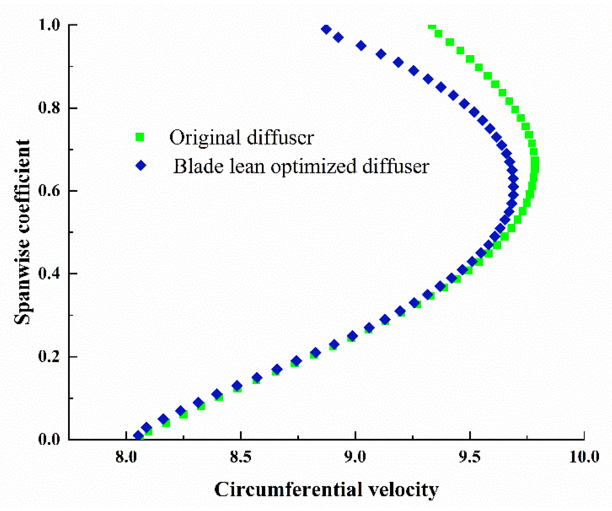
Figure 13 shows the static pressure and streamlines in the diffuser outlet section. Static pressure at the outlet of the blade lean optimized diffuser increases significantly, and the static pressure recovery coefficient is 2.64% higher than that of the original diffuser. This is because the blade inlet profile of the blade lean optimized diffuser changes from a straight line to a curve, the structure of the leading edge is more in line with the fluid flow trend, making it difficult to flow off, as shown in Figure 13b. Figure 14 shows the circumferential velocity distribution along the spanwise wall at the inlet edge of the diffuser. The fluid velocity at the shroud of the blade lean optimized diffuser is significantly lower than that of the original diffuser. The blade lean scheme improves the static pressure conversion capacity of the diffuser and effectively reduces the circumferential velocity component of the fluid and velocity difference at the leading edge of the diffuser. Therefore, the local hydraulic loss of the diffuser is reduced and the diffuser efficiency and static pressure recovery coefficient are improved.
5.2. Response Surface of the Sweep Optimized Diffuser
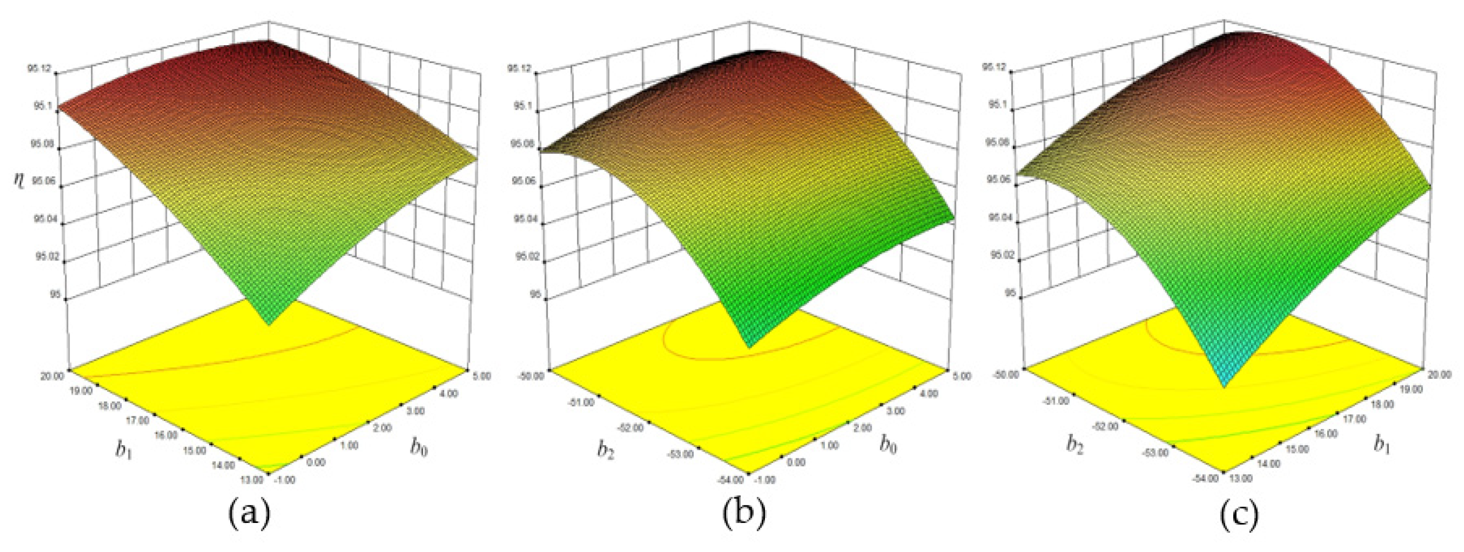
As described in Section 4.2, b0 is located at the outlet edge on the hub, b1 is located at the outlet edge on the shroud, and b2 is located at the inlet edge on the hub. One factor, b0, b1, or b2, was fixed to zero and the influence of the other pair of factors on the response was analyzed. Figure 15a shows the influence of interaction between b0 and b1 on the diffuser efficiency when b2 is at a medium level. High levels of b0 and b1 resulted in the optimal diffuser efficiency. Figure 15b shows the effect of interaction between b0 and b2 on the diffuser efficiency when b1 is at a medium level. Factor b2 has a large impact on diffuser efficiency, which increases when the outlet edge on the hub moves to the outlet of the diffuser (medium–high b2). Figure 15c shows that the interaction between b1 and b2 has a significant influence on diffuser efficiency when b0 is at a medium level. A medium–high level of b2 and a high level of b1 resulted in the highest diffuser efficiency.
Figure 16a shows that the static pressure recovery coefficient reaches the highest value when b0 is low and b1 is high. When the blade outlet on the hub moves towards the inlet of the diffuser (low b0) and the blade outlet on the shroud side moves towards the outlet of the diffuser (high b1), the static pressure recovery capacity of the diffuser improved. Figure 16b shows that the static pressure recovery coefficient is optimal when b0 is low and b2 is medium. Figure 16c shows that the static pressure recovery coefficient reaches the highest value when b1 is high and b2 is medium. The blade outlet edge on the hub moves towards the inlet of the diffuser (low b0) and the blade outlet edge on the shroud moves towards the outlet of diffuser (high b1), whereas the position of the blade inlet edge does not change at medium b2 and the static pressure recovery coefficient can be increased.
Figure 17a shows that non-uniformity decreases when high b0 interacts with high b1. The outlet edge of the diffuser moves from the shroud to the hub (high b0 and b1), which can improve the flow uniformity in the diffuser. Figure 17b shows that non-uniformity is relatively low when b0 is high. Factor b2 has no obvious effect on non-uniformity and provided b0 moves to a higher level, flow non-uniformity in the diffuser will decrease. A high level of b0 is the key to optimizing flow uniformity in the diffuser but does not improve the static pressure recovery coefficient. Figure 17c shows that flow non-uniformity in the diffuser is low when b1 is high. The change in direction of flow on the inlet side of the diffuser hub has very little effect on non-uniformity in the diffuser, while moving the outlet side of the diffuser towards the outlet direction (high b0 and b1) improves the flow uniformity.
According to the measured data and response surface analysis, the factor b2 has the largest influence on the diffuser efficiency, followed by b1, and the influence of b0 is the smallest. The diffuser efficiency exhibits an upward trend with increasing b1 and b0 and an inverted-U trend with increasing b2. The influence of factor b0 on the static pressure recovery coefficient of diffuser is the largest, followed by b2, and b1 is the smallest. The static pressure recovery coefficient increases with decreasing b0, increases slowly with increasing b1, and first increases and then decreases with increasing b2. At the same time, non-uniformity decreases with increasing b0 and b1, whereas changes in b2 have very little effect on flow uniformity. The optimal solution was obtained by considering the influence of b0, b1, and b2 on diffuser efficiency, static pressure recovery coefficient, and non-uniformity, as shown in Table 7. The results show that when b0 has the medium–low level of 1.5, b1 has the high level of 20, and b2 has the medium level of –52, the diffuser efficiency and static pressure recovery coefficient can be improved.
Figure 18 shows the inlet and outlet profile positions of the original diffuser and the sweep optimized diffuser on the meridian plane. In the original pump, b0 = 0, b1 = 14, and b2 = −52.4. In the sweep scheme, the values are b0 = 1.5, b1 = 20, and b2 = −52. The position of the shroud surface at the blade outlet (b1) changes greatly. When the shroud edge of the blade outlet moves towards the outlet of the diffuser, the influence of b1 on the diffuser can be clearly observed.
The optimized blade trailing edge extends the diffuser outlet on the shroud side, as shown in Figure 18. The increased blade trailing edge can better drain the fluid to the diffuser outlet, whereas there is sufficient time for velocity exchange with the high-speed main body when the fluid flows through the extended blade trailing edge (Figure 19b), thereby reducing the velocity gradient and improving flow uniformity at the outlet of the diffuser. In Figure 19a, low-energy fluid in the original diffuser does not fully mix with the high-speed mainstream and large differences in velocity lead to increased hydraulic losses in the diffuser, which affects the outlet flow uniformity. Therefore, the flow inside the sweep optimized diffuser is more reasonable. Compared with the original diffuser, flow non-uniformity is reduced by 13.1%.
6. Discussion
The origin of the hub corner separation vortex can be explained by reference to Figure 20. The vortex originates from two positions: the inlet of the diffuser, represented by A, and the central of the diffuser, represented by B. In region A1, the curvature difference between the meridian shroud and the hub surface leads to the development of spanwise differential pressure, driving secondary flow from the shroud to the hub, which scours the inlet edge, thus forming a spanwise pressure difference, represented by region L. As the flow develops, swirling flow occurs at the hub in region A2 and rushes against the transverse pressure gradient towards the PS. In the center of the diffuser (region B1), the working fluid must flow against the reverse pressure gradient, resulting in an increase in low-momentum fluid on the hub. Then, the increased amount of low-momentum fluid is deflected towards the SS under the transverse differential pressure at the hub in region B2. Finally, a large hub corner separation vortex appears in the corner of the blade, accounting for about 1/3 of the area of the hub. In a previous study [20], the spanwise secondary flow from shroud to hub at the trailing edge of the diffuser was shown to scour low-energy fluid, thereby inhibiting the hub corner vortex. However, our results suggest that low-energy fluid accumulated on the suction surface cannot overcome the spanwise pressure difference between the shroud and the hub and can only reverse the flow along the hub surface, forming a secondary flow angle to suppress the vortex in region B3.
To explain the improvement in diffuser efficiency and diffuser uniformity, the spanwise/transverse pressure difference in the diffuser were quantified, as shown in Figure 21 and Figure 22. At the inlet of the diffuser, the spanwise pressure difference in the blade lean optimized diffuser is significantly higher, resulting in enhanced transverse secondary flow (Figure 21). The spanwise pressure difference in the sweep optimized diffuser is significantly lower than in the blade lean optimized diffuser; therefore, the transverse pressure difference caused by spanwise secondary flow at the inlet of the diffuser is weakened. Moreover, both the transverse pressure differences at the inlet of the sweep optimized diffuser and blade lean optimized diffuser increase (Figure 22), which offsets the transverse pressure difference and suppresses the hub corner separation vortex.
At the outlet of the diffuser, the spanwise pressure difference at the trailing edge in the blade lean optimized diffuser is lower than in the original diffuser, as shown in Figure 19, which is not conductive to improving the diffuser performance. However, the spanwise pressure difference at the trailing edge in the sweep optimized diffuser is highest; therefore, low-energy fluid in the corner area becomes caught up in the main flow and is dragged toward the outlet of the diffuser, thus improving flow uniformity in the diffuser. When the low-energy fluid at the trailing edge of the diffuser is restrained and the difference between the mainstream velocity is weakened, mixing losses at the diffuser outlet are reduced and the hydraulic efficiency of the diffuser is improved.
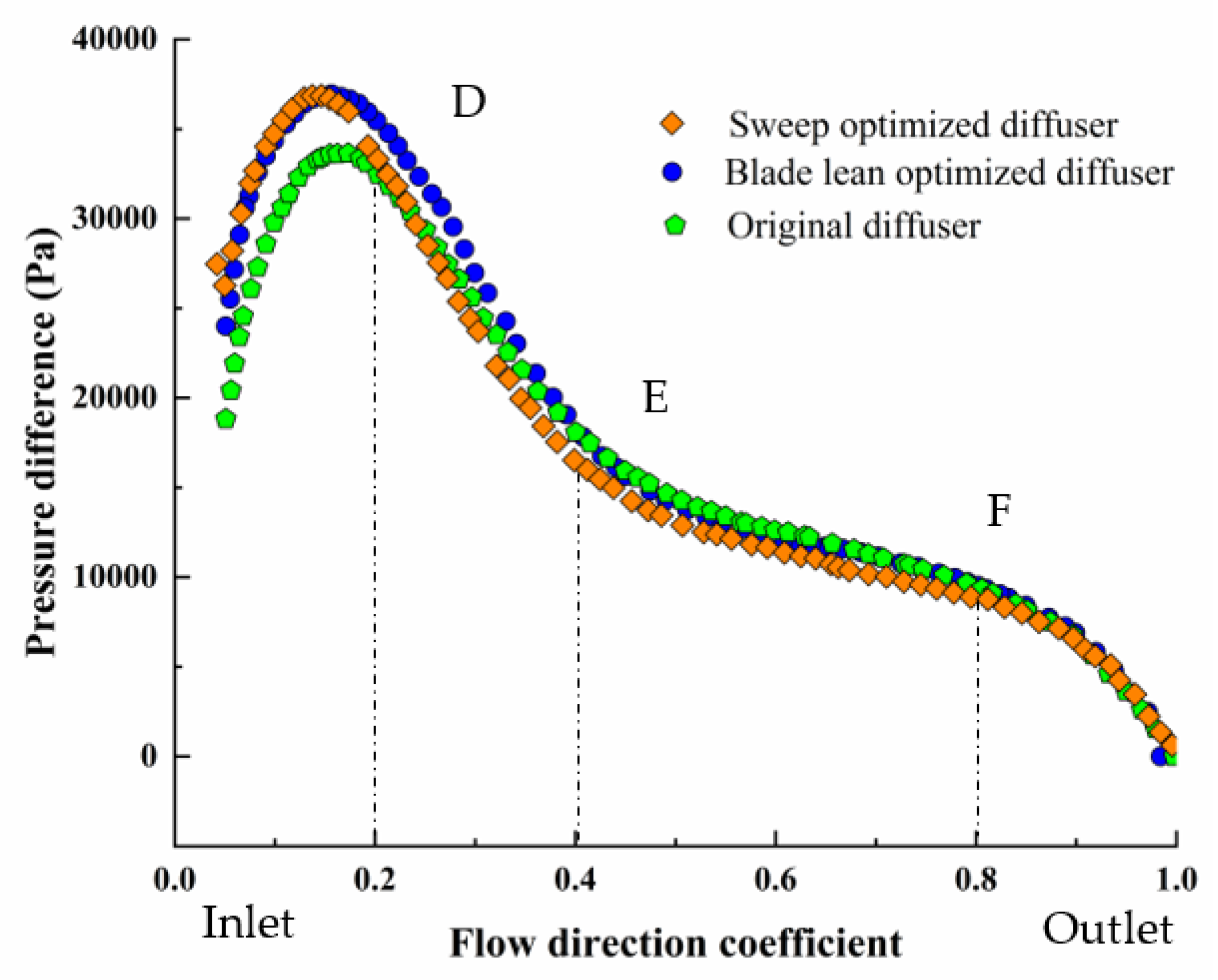
The reduced low-energy fluid in the center of the diffuser and the spanwise differential pressure drainage at the trailing edge of the diffuser lead to more uniform outflow. In Figure 21, the spanwise pressure difference in the center of the diffuser changes from negative to positive, and the direction is reversed. Therefore, the low-energy fluid originally returns from the hub to the low-pressure area in the center, which suppresses the corner separation vortex and improves the outlet flow uniformity in the diffuser. In Figure 22, the transverse pressure difference in the sweep optimized diffuser is less than in the blade lean optimized diffuser in the DF stage; however, the reverse pressure gradient in the DE stage is greater than in the blade lean optimized diffuser. The amount of low-energy fluid in the center of the diffuser increases and the reduced transverse pressure difference in the center cannot reduce the amount of low-energy fluid in the suction surface corner. However, the transverse pressure difference between the PS and SS in the EF stage decreases; therefore, the reverse pressure gradient in the flow direction decreases and the amount of low-energy fluid in the corner decreases.
Figure 23 compares the static pressure on the shroud of the diffuser under different scenarios. The static pressure on the shroud of the blade lean optimized diffuser is higher than that of the original diffuser, and the increase in static pressure on the PS is more obvious. Therefore, the blade lean optimized diffuser can convert more kinetic energy in the fluid into static pressure energy and the static pressure recovery coefficient of the diffuser can be improved. The static pressure on the shroud of the sweep optimized diffuser does not always increase; however, it is higher than those of other diffusers at the stage of 10–65% flow direction and decreases at the outlet section. The reason for this is that the flow direction at the outlet of the sweep optimized diffuser changes greatly and the distance between the working fluid flowing through the diffuser and the trailing edge of the blade increases. Thus, the static pressure decreases and the static pressure recovery coefficient of the diffuser does not increase significantly.
7. Conclusions
Aimed at controlling the hub corner separation vortex and corresponding high hydraulic losses in the bowl diffuser of a multistage submersible pump, the diffuser was optimized in terms of blade lean and sweep. The blade structure can be controlled digitally and accurately using parametric equations. CFD simulations and central combination tests were used to optimize different blade lean and sweep schemes. The internal flow field and static pressure distribution in the diffuser were thoroughly investigated.
At the hub corner of the diffuser, the low-energy fluid induced by spanwise and transverse pressure at the inlet of the diffuser blade overcomes the streamwise pressure gradient and accumulates in the mid-section of the suction surface. However, the accumulated low-energy fluid cannot overcome the spanwise pressure difference between the shroud and the hub, the flow direction is reversed toward the inlet, and the hub corner vortex forms. Optimization of the blade lean and sweep can improve the transverse pressure in the diffuser. In particular, the hub–shroud spanwise pressure can be enhanced in order to drive the low-energy fluid towards the center of the blade, rather than reversing it. This suppresses the hub corner vortex and improves the hydraulic performance of the diffuser.
In the blade lean scheme, the transverse pressure difference at the inlet of the diffuser increases, which inhibits the formation of the hub corner separation vortex. However, the spanwise pressure difference at the inlet of the suction surface increases, and the spanwise pressure difference at the trailing edge decreases, which does not improve the performance of the diffuser. Moreover, since the structure of the leading edge of the blade changes and the fluid flows close to the blade after entering the diffuser, flow separation is difficult to induce. The fluid kinetic energy and static pressure energy are fully converted, the static pressure recovery coefficient increases by 2.64% compared with the original diffuser, and the diffuser efficiency increases by 0.32%. Optimization of blade lean can improve the static pressure recovery coefficient and diffuser efficiency but does not improve flow uniformity in the diffuser.
The sweep scheme can reduce the spanwise pressure difference and transverse pressure difference at the inlet of the diffuser, increase the spanwise pressure difference at the outlet of the diffuser, inhibit the formation of the hub corner separation vortex, and improve the flow uniformity of the diffuser. However, the increase in the reverse pressure gradient in the flow direction of the diffuser limits the improvement in diffuser efficiency. Sweep design can effectively reduce flow non-uniformity in the diffuser; however, the influence of the static pressure recovery coefficient is small.
Author Contributions
Conceptualization, P.C. and C.N.; Formal analysis, C.N. and X.G.; Methodology, C.N. and R.Z.; Project administration, P.C.; Software, R.Z.; Writing—original draft, C.N.; Writing—review & editing, X.G. All authors have read and agreed to the published version of the manuscript.
Funding
This research was funded by the Natural Science Foundation of Jiangsu Province: BK 20190847, China Postdoctoral Science Foundation: 2019M661744, the National Natural Science Foundation of China: 51879120, and the Priority Academic Program Development of Jiangsu Higher Education Institutions (PAPD).
Institutional Review Board Statement
Not applicable.
Informed Consent Statement
Not applicable.
Data Availability Statement
The data that support the findings of this study are available from the corresponding author upon reasonable request.
Acknowledgments
A huge thanks is due to the editor and reviewers for their valuable comments to improve the quality of this paper.
Conflicts of Interest
The authors declare no conflict of interest.
Abbreviations
| Cp | Static pressure recovery coefficient |
| CCD | Center composite design |
| H | Head (m) |
| PS | Pressure surface of blade |
| SS | Suction surface of blade |
| k | Turbulent kinetic energy (m²/s²) |
| Pin | Total pressure of pump inlet (Pa) |
| Pout | Total pressure of pump outlet (Pa) |
| Pt3 | Total pressure of diffuser inlet (Pa) |
| Pt4 | Total pressure of diffuser outlet (Pa) |
| Ps3 | Static pressure of diffuser inlet (Pa) |
| Ps4 | Static pressure of diffuser outlet (Pa) |
| ρ | Density of fluid (kg/m³) |
| µt | Turbulent viscosity (kg/m·s) |
| ε | Turbulent energy dissipation (m²/s³) |
| ϕHub | Wrap angle of hub (°) |
| ϕShroud | Wrap angle of shroud (°) |
| θ | Starting angle (°) |
| ∆θ | Starting angle difference (°) |
| θHub | Starting angle of hub flow surface (°) |
| θShroud | Starting angle of shroud flow surface (°) |
| β | Sweep angle of diffuser (°) |
| ɳ | Efficiency of diffuser (%) |
| ζi | Non-uniformity |
References
- Wang, H.L.; Hu, Q.X.; Yang, Y.; Wang, C. Performance Differences of Electrical Submersible Pump under Variable Speed Schemes. Int. J. Simul. Model. 2021, 20, 76–86. [Google Scholar] [CrossRef]
- Zhou, J.; Zhao, M.; Wang, C.; Gao, Z. Optimal Design of Diversion Piers of Lateral Intake Pumping Station Based on Orthogonal Test. Shock. Vib. 2021, 2021, 6616456. [Google Scholar] [CrossRef]
- Shi, L.; Zhu, J.; Tang, F.; Wang, C. Multi-Disciplinary Optimization Design of Axial-Flow Pump Impellers Based on the Approximation Model. Energies 2020, 13, 779. [Google Scholar] [CrossRef] [Green Version]
- Zhang, L.; Wang, C.; Zhang, Y.; Xiang, W.; He, Z.; Shi, W. Numerical study of coupled flow in blocking pulsed jet impinging on a rotating wall. J. Braz. Soc. Mech. Sci. Eng. 2021, 43, 508. [Google Scholar] [CrossRef]
- Wang, H.; Long, B.; Wang, C.; Han, C.; Li, L. Effects of the Impeller Blade with a Slot Structure on the Centrifugal Pump Performance. Energies 2020, 13, 1628. [Google Scholar] [CrossRef]
- Wang, H.; Qian, Z.; Zhang, D.; Wang, T.; Wang, C. Numerical Study of the Normal Impinging Water Jet at Different Impinging Height, Based on Wray–Agarwal Turbulence Model. Energies 2020, 13, 1744. [Google Scholar] [CrossRef] [Green Version]
- Bellary, S.A.I.; Husain, A.; Samad, A. Effectiveness of meta-models for multi-objective optimization of centrifugal impeller. J. Mech. Sci. Technol. 2014, 28, 4947–4957. [Google Scholar] [CrossRef]
- Bellary, S.A.I.; Samad, A.; Couckuyt, I.; Dhaene, T. A comparative study of kriging variants for the optimization of a turbomachinery system. Eng. Comput. 2016, 32, 49–59. [Google Scholar] [CrossRef]
- Huang, K.L.; Yuan, J.P.; Si, Q.R.; Lin, G. Numerical simulation of pressure pulsation in multistage centrifugal pump under multi-operation condition. J. Drain. Irrig. Mach. Eng. 2019, 37, 387–392. [Google Scholar]
- Tong, S.G.; Zhao, H.; Liu, H.Q.; Tong, Z.M.; Yue, Y.U.; Tang, N. Optimization calculation method for efficiency of multistage split case centrifugal pump. J. Zhejiang Univ. Eng. Sci. 2019, 53, 988–996. [Google Scholar]
- Stel, H.; Sirino, T.; Ponce, F.; Chiva, S.; Morales, R. Numerical investigation of the flow in a multistage electric submersible pump. J. Pet. Sci. Eng. 2015, 136, 41–54. [Google Scholar] [CrossRef]
- Heo, M.W.; Ma, S.-B.; Shim, H.S.; Kim, K.Y. High-efficiency design optimization of a centrifugal pump. J. Mech. Sci. Technol. 2016, 30, 3917–3927. [Google Scholar] [CrossRef]
- Murugesan, C.; Rudramoorthy, R. Numerical And Experimental Study Of Single stage And Multistage Centrifugal Mixed Flow Submersible Borewell Pumps. Int. J. Fluid Mach. Syst. 2016, 9, 107–118. [Google Scholar] [CrossRef] [Green Version]
- Kim, J.-H.; Cho, B.-M.; Kim, S.; Lee, Y.-K.; Choi, Y.-S. Steady and Unsteady Flow Characteristics of a Multi-stage Centrifugal Pump under Design and Off-design Conditions. Int. J. Fluid Mach. Syst. 2019, 12, 64–70. [Google Scholar] [CrossRef]
- Rosic, B.; Xu, L. Blade Lean and Shroud Leakage Flows in Low Aspect Ratio Turbines. J. Turbomach. 2011, 134, 031003. [Google Scholar] [CrossRef]
- Razavi, S.R.; Sammak, S.; Boroomand, M. Multidisciplinary Design and Optimizations of Swept and Leaned Transonic Rotor. J. Eng. Gas Turbines Power 2017, 139, 122601. [Google Scholar] [CrossRef]
- He, X.; Zheng, X. Mechanisms of Sweep on the Performance of Transonic Centrifugal Compressor Impellers. Appl. Sci. 2017, 7, 1081. [Google Scholar] [CrossRef] [Green Version]
- He, X.; Zheng, X. Performance improvement of transonic centrifugal compressors by optimization of complex three-dimensional features. Proc. Inst. Mech. Eng. Part G J. Aerosp. Eng. 2016, 231, 2723–2738. [Google Scholar] [CrossRef]
- Bagshaw, D.A.; Ingram, G.; Gregory-Smith, D.G.; Stokes, M.R.; Harvey, N.W. The design of three-dimensional turbine blades combined with profiled endwalls. Proc. Inst. Mech. Eng. Part A J. Power Energy 2008, 222, 93–102. [Google Scholar] [CrossRef] [Green Version]
- Goto, A.; Zangeneh, M. Hydrodynamic Design of Pump Diffuser Using Inverse Design Method and CFD. J. Fluids Eng. 2002, 124, 319–328. [Google Scholar] [CrossRef]
- Goto, A.; Nohmi, M.; Sakurai, T.; Sogawa, Y. Hydrodynamic Design System for Pumps Based on 3-D CAD, CFD, and Inverse Design Method. J. Fluids Eng. 2002, 124, 329–335. [Google Scholar] [CrossRef]
- Scillitoe, A.; Tucker, P.G.; Adami, P. Numerical Investigation of Three-Dimensional Separation in an Axial Flow Compressor: The Influence of Freestream Turbulence Intensity and Endwall Boundary Layer State. J. Turbomach. 2016, 139, 021011. [Google Scholar] [CrossRef]
- Şahin, F.C. Experimental investigation on flow improvement in compressor cascades. Int. J. Energy Res. 2016, 41, 526–539. [Google Scholar] [CrossRef]
- Ananthakrishnan, K.; Govardhan, M. Influence of fillet shapes on secondary flow field in a transonic axial flow turbine stage. Aerosp. Sci. Technol. 2018, 82–83, 425–437. [Google Scholar] [CrossRef]
- Shi, W.; Zhou, L.; Lu, W.; Xu, L.; Li, W. Numerical Simulation and Experimental Study of Different Stages Deep-Well Centrifugal Pump. J. Comput. Theor. Nanosci. 2013, 10, 2897–2901. [Google Scholar] [CrossRef]
- Zhou, L.; Shi, W.; Li, W.; Agarwal, R. Numerical and Experimental Study of Axial Force and Hydraulic Performance in a Deep-Well Centrifugal Pump With Different Impeller Rear Shroud Radius. J. Fluids Eng. 2013, 135, 104501. [Google Scholar] [CrossRef]
- Yuan, S.Q.; He, W.T.; Si, Q.R.; Yuan, J.P.; Zhang, H.Y.; Cui, Q.L. Numerical simulation on gas-liquid two-phase flow in centrifugal pump based on MUSIG model. J. Drain. Irrig. Mach. Eng. 2021, 39, 1–7. [Google Scholar]
- Yakhot, V.; Orszag, S.A. Renormalization group analysis of turbulence. I. Basic theory. J. Sci. Comput. 1986, 1, 3–51. [Google Scholar] [CrossRef]
- Lam, S.H. On the RNG theory of turbulence. Phys. Fluids A Fluid Dyn. 1992, 4, 1007–1017. [Google Scholar] [CrossRef]
- Mompean, G. Numerical simulation of a turbulent flow near a right-angled corner using the Speziale non-linear model with RNG K–ε equations. Comput. Fluids 1998, 27, 847–859. [Google Scholar] [CrossRef]
- Cao, P.; Zhu, R.; Yin, G. Spike-type disturbances due to inlet distortion in a centrifugal pump. Renew. Energy 2021, 165, 288–300. [Google Scholar] [CrossRef]
- Zhou, L.; Wang, W.; Hang, J.; Shi, W.; Yan, H.; Zhu, Y. Numerical Investigation of a High-Speed Electrical Submersible Pump with Different End Clearances. Water 2020, 12, 1116. [Google Scholar] [CrossRef] [Green Version]
- Zhou, L.; Bai, L.; Shi, W.; Li, W.; Wang, C.; Ye, D. Numerical analysis and performance experiment of electric submersible pump with different diffuser vanes number. J. Braz. Soc. Mech. Sci. Eng. 2018, 40, 89. [Google Scholar] [CrossRef]
Figure 1.
Geometrical model of the impeller and bowl diffuser.

Figure 2.
Multistage submersible pump calculation domain.

Figure 3.
Mesh of impeller and diffuser for multistage submersible pump. (a) Mesh of impeller. (b) Mesh of diffuser.
Figure 3.
Mesh of impeller and diffuser for multistage submersible pump. (a) Mesh of impeller. (b) Mesh of diffuser.

Figure 4.
Testing apparatus [32]. 1. Data acquisition instrument. 2. Frequency inverter. 3. Electromagnetic flowmeter. 4. The valve. 5. Computer. 6. Pressure sensor. 7. Pump. 8. Motor.
Figure 4.
Testing apparatus [32]. 1. Data acquisition instrument. 2. Frequency inverter. 3. Electromagnetic flowmeter. 4. The valve. 5. Computer. 6. Pressure sensor. 7. Pump. 8. Motor.
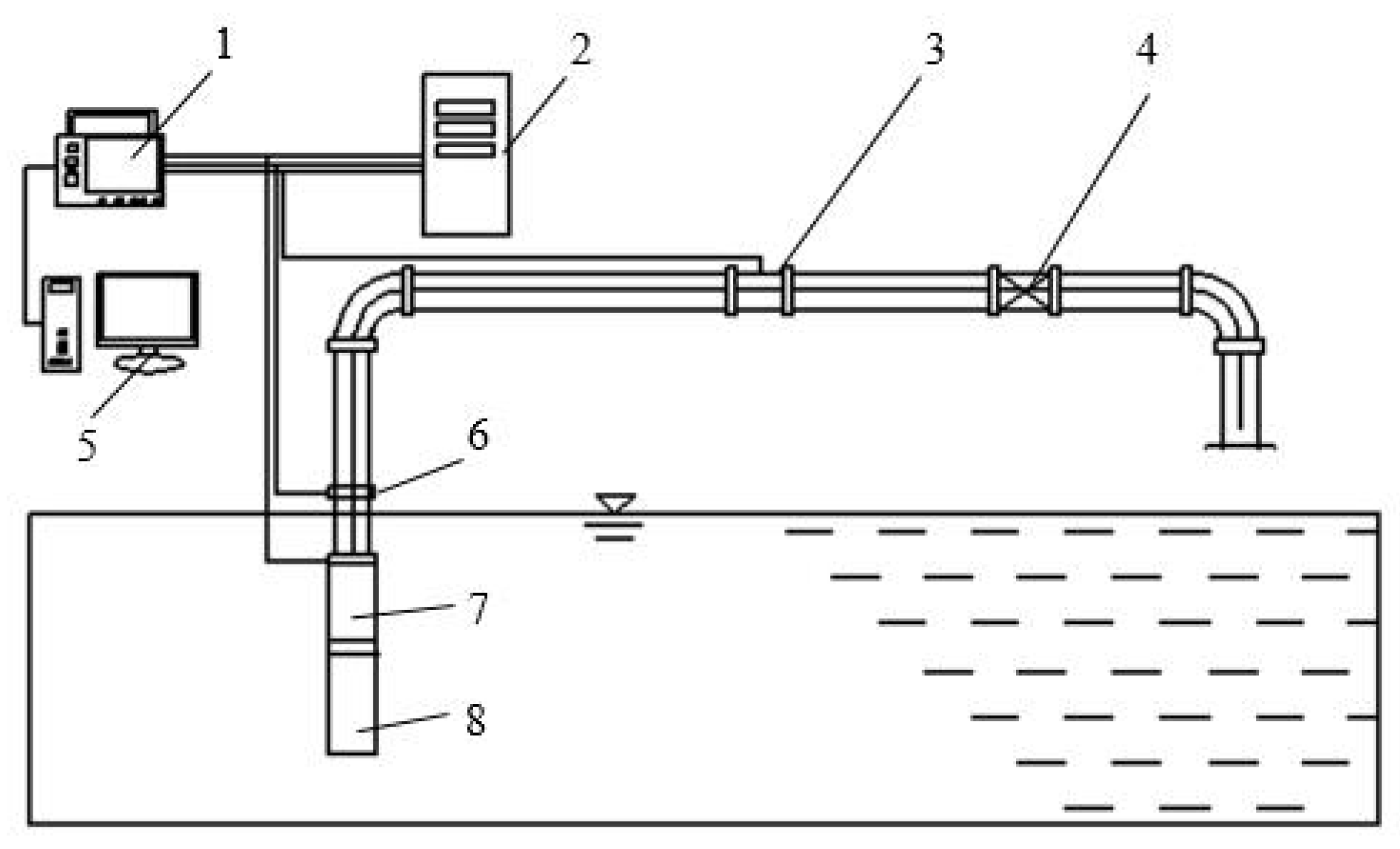
Figure 5.
Comparison of head obtained by experiment and simulation.
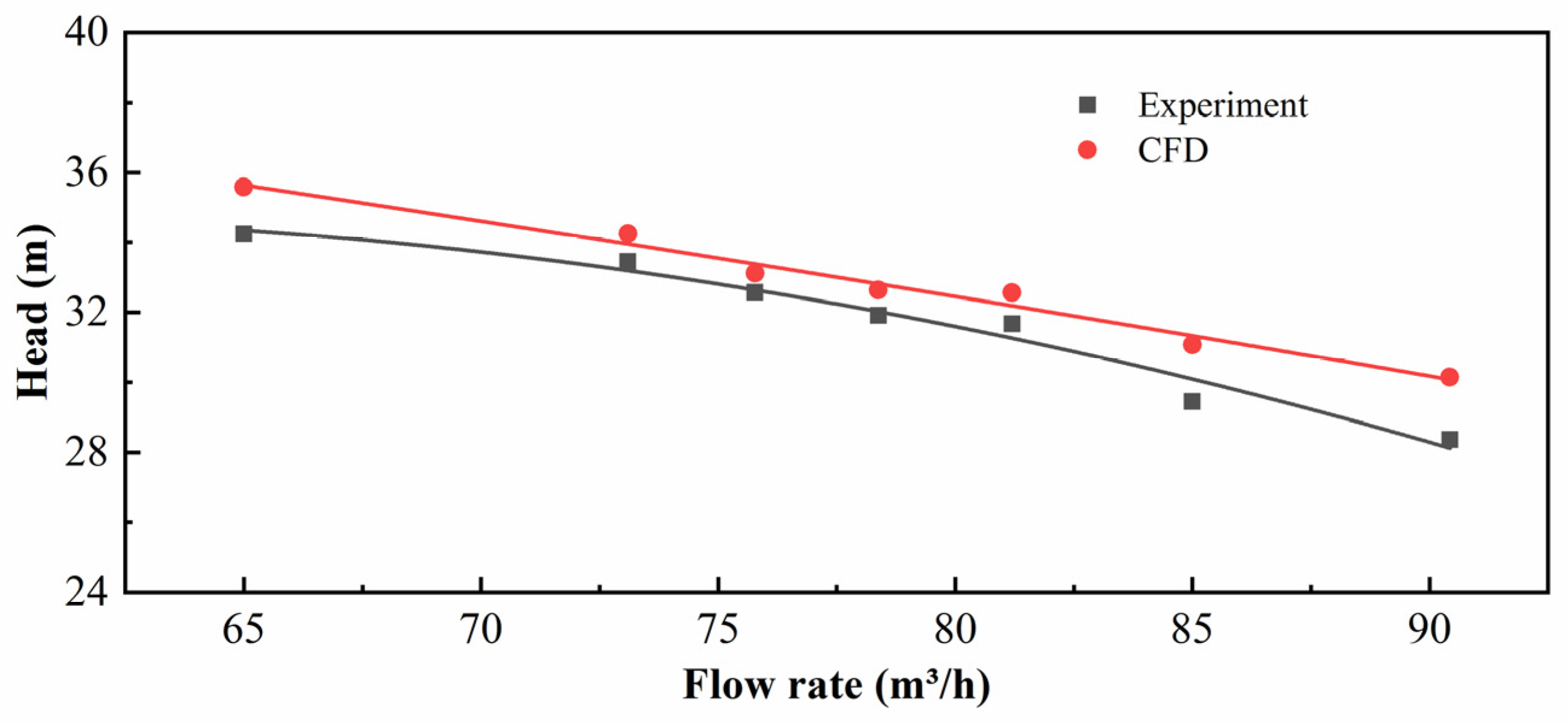
Figure 6.
Blade lean coordinate system and blade leading edge angle of diffuser (from inlet view).
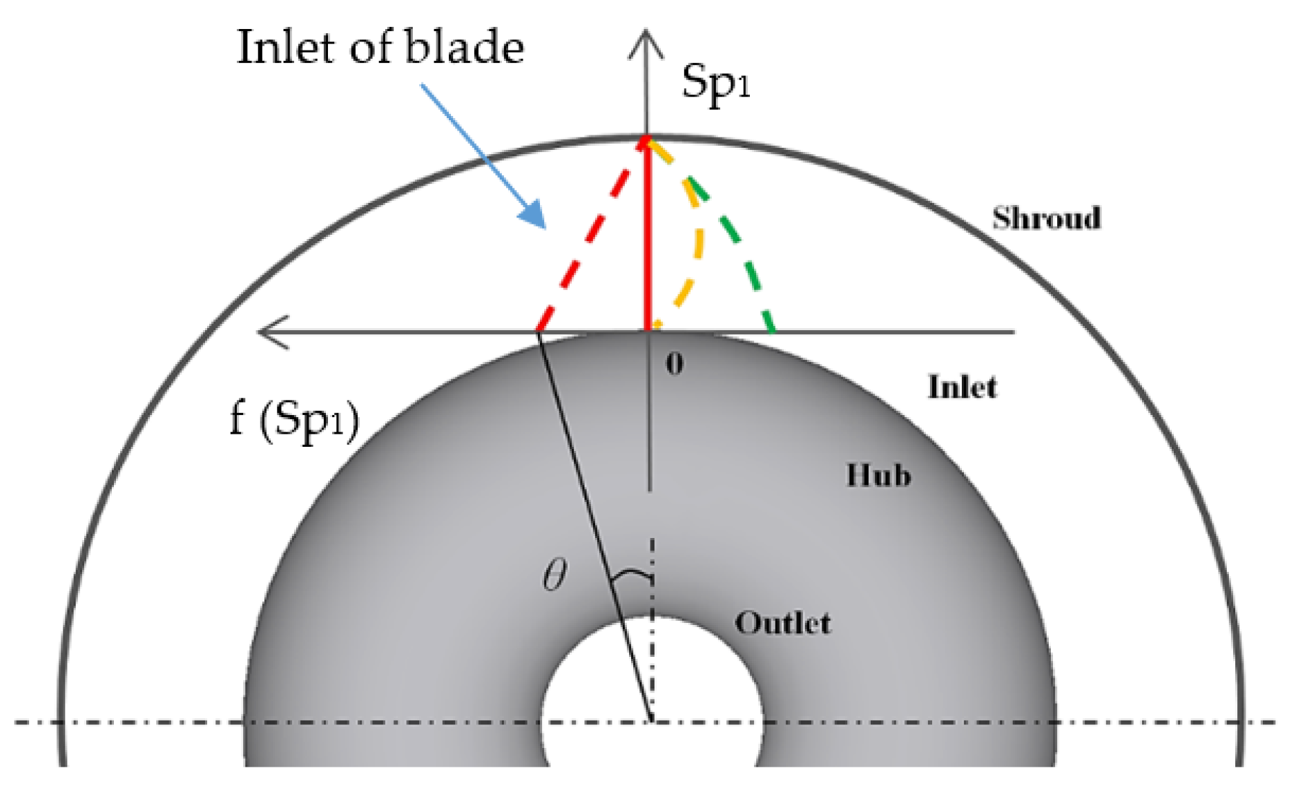
Figure 7.
Sweep coordinate system and blade sweep angle of diffuser sweep design (from meridional view).
Figure 7.
Sweep coordinate system and blade sweep angle of diffuser sweep design (from meridional view).
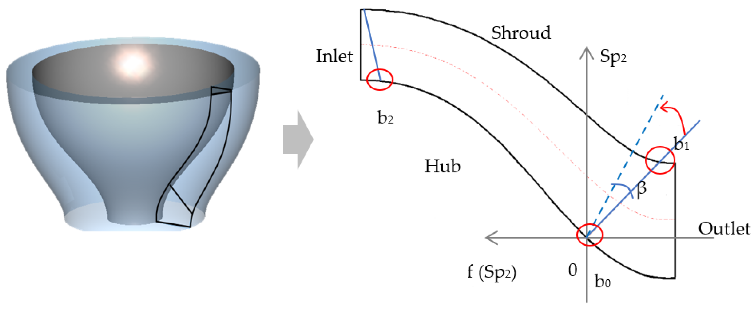
Figure 8.
Response surface of diffuser efficiency in blade lean optimization (a) a2 = 0. (b) a1 = 0. (c) a0 = 0.
Figure 8.
Response surface of diffuser efficiency in blade lean optimization (a) a2 = 0. (b) a1 = 0. (c) a0 = 0.
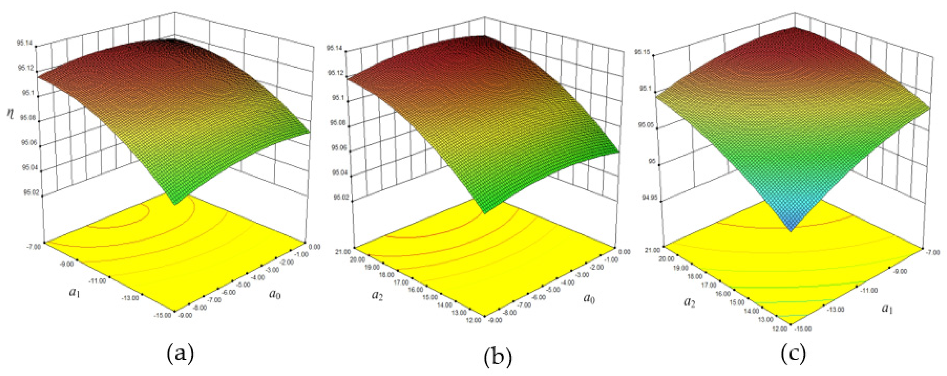
Figure 9.
Response surface of pressure recovery coefficient in blade lean optimization (a) a2 = 0. (b) a1 = 0. (c) a0 = 0.
Figure 9.
Response surface of pressure recovery coefficient in blade lean optimization (a) a2 = 0. (b) a1 = 0. (c) a0 = 0.

Figure 10.
Response surface of non-uniformity in blade lean optimization. (a) a2 = 0. (b) a1 = 0. (c) a0 = 0.
Figure 10.
Response surface of non-uniformity in blade lean optimization. (a) a2 = 0. (b) a1 = 0. (c) a0 = 0.
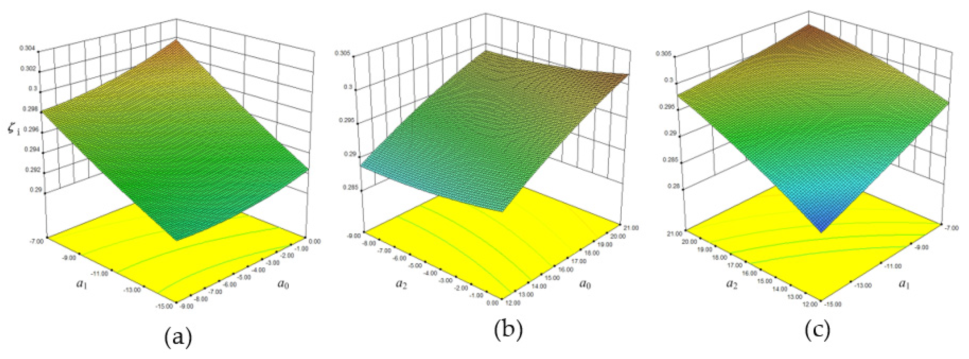
Figure 11.
Blade inlet edge profile of diffuser in circumferential view (first row) and inlet view (second row). (a) Original diffuser. (b) Blade lean optimized diffuser.
Figure 11.
Blade inlet edge profile of diffuser in circumferential view (first row) and inlet view (second row). (a) Original diffuser. (b) Blade lean optimized diffuser.

Figure 12.
Profiles of inlet edge and spanwise distribution of stacking angle.

Figure 13.
Comparison of static pressure and streamlines at diffuser outlet surface. (a) Original diffuser and (b) Blade lean optimized diffuser.
Figure 13.
Comparison of static pressure and streamlines at diffuser outlet surface. (a) Original diffuser and (b) Blade lean optimized diffuser.
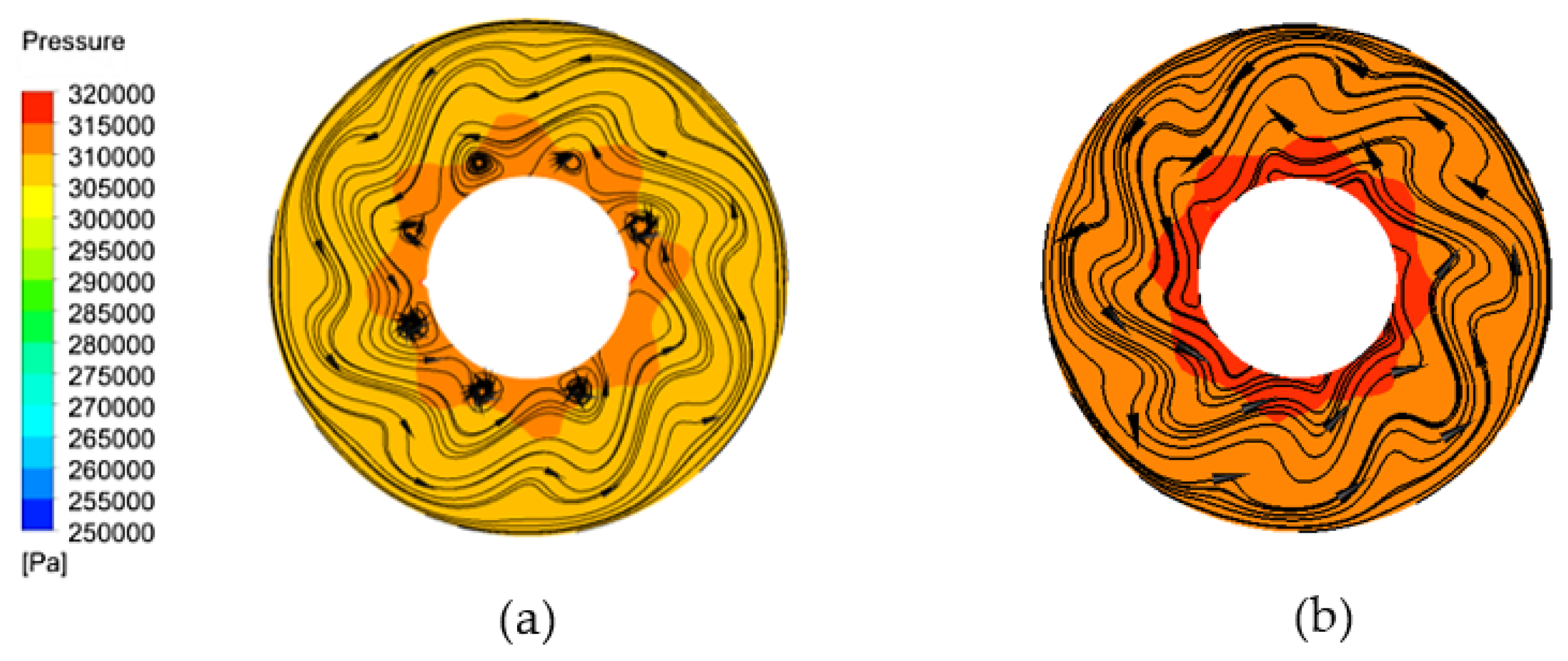
Figure 14.
Comparison of pitch-averaged circumferential velocity distribution at leading edge of diffuser blade.
Figure 14.
Comparison of pitch-averaged circumferential velocity distribution at leading edge of diffuser blade.

Figure 15.
Response surface of diffuser efficiency in sweep optimization. (a) b2 = 0. (b) b1 = 0. (c) b0 = 0.
Figure 15.
Response surface of diffuser efficiency in sweep optimization. (a) b2 = 0. (b) b1 = 0. (c) b0 = 0.

Figure 16.
Response surface of pressure recovery coefficient in sweep optimization. (a) b2 = 0. (b) b1 = 0. (c) b0 = 0.
Figure 16.
Response surface of pressure recovery coefficient in sweep optimization. (a) b2 = 0. (b) b1 = 0. (c) b0 = 0.
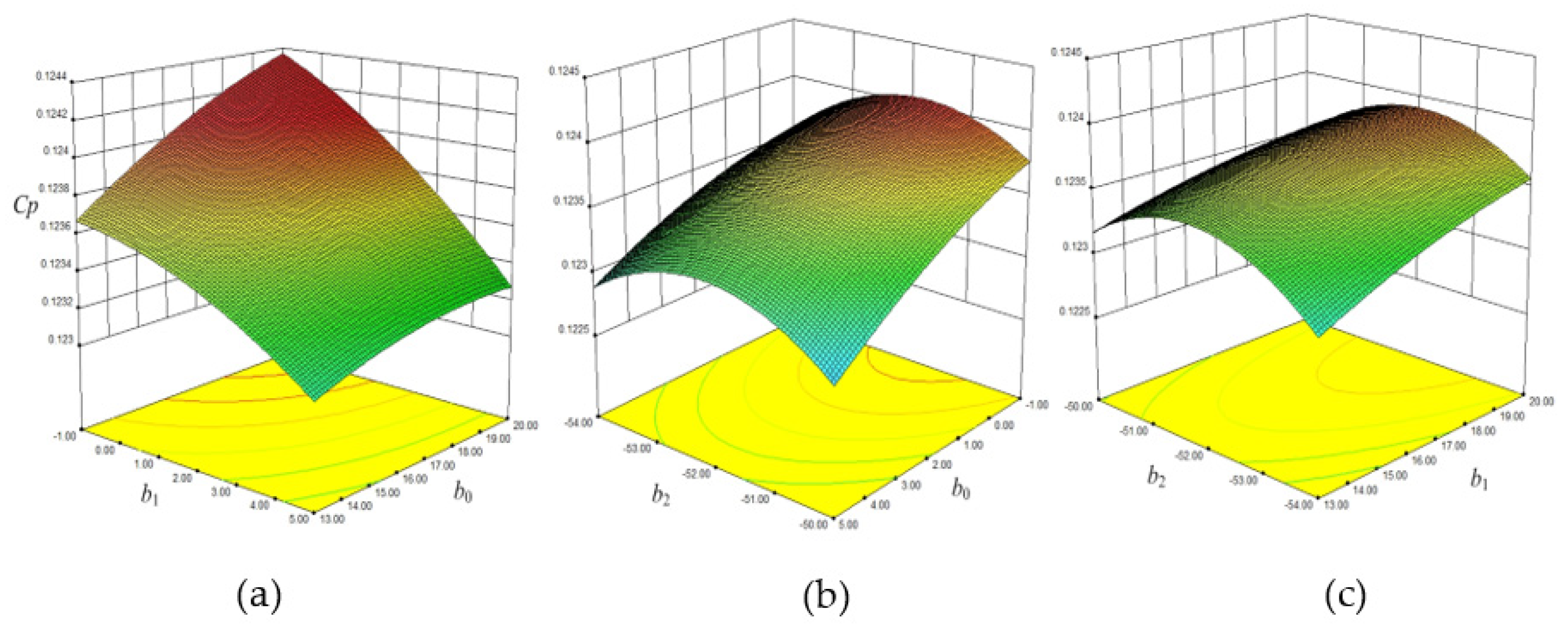
Figure 17.
Response surface of non-uniform in sweep optimization. (a) b2 = 0. (b) b1 = 0. (c) b0 = 0.
Figure 17.
Response surface of non-uniform in sweep optimization. (a) b2 = 0. (b) b1 = 0. (c) b0 = 0.
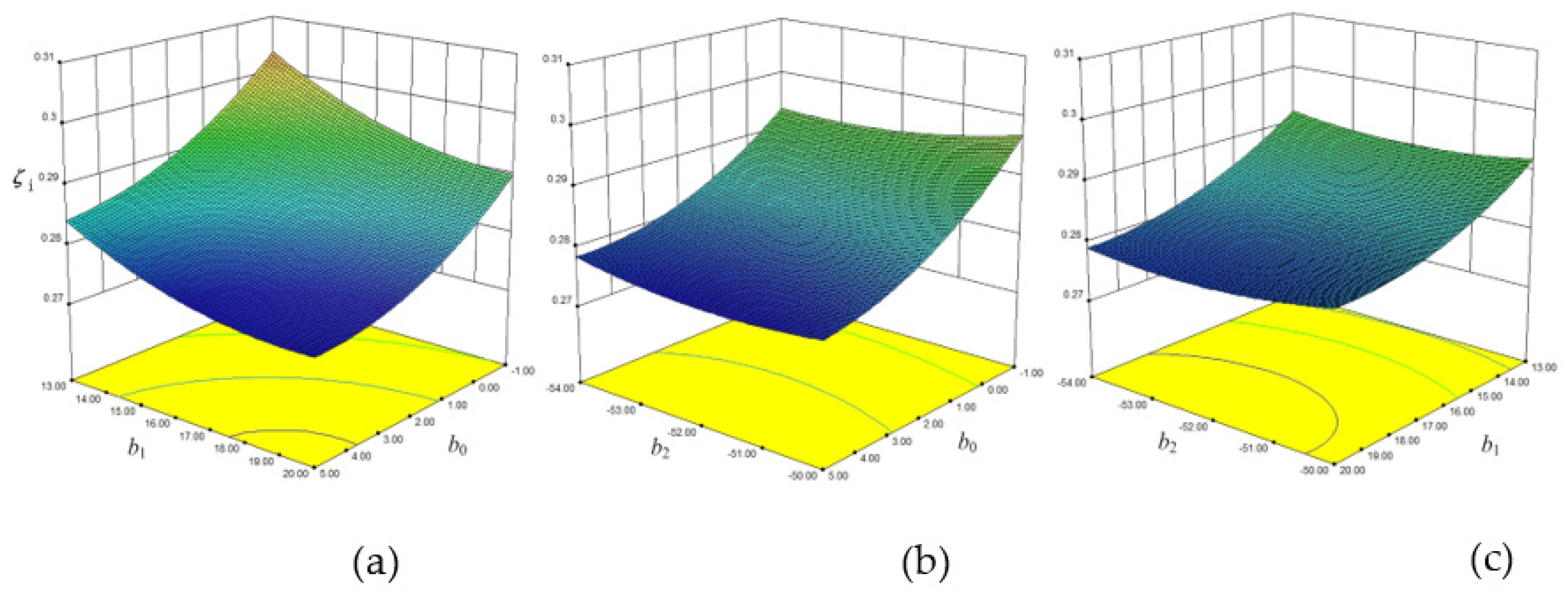
Figure 18.
Comparison of sweep optimized meridional plane and the original of diffuser.

Figure 19.
Comparison of the streamlines of blade outlet edge. (a) Original diffuser. (b) Sweep optimized diffuser.
Figure 19.
Comparison of the streamlines of blade outlet edge. (a) Original diffuser. (b) Sweep optimized diffuser.
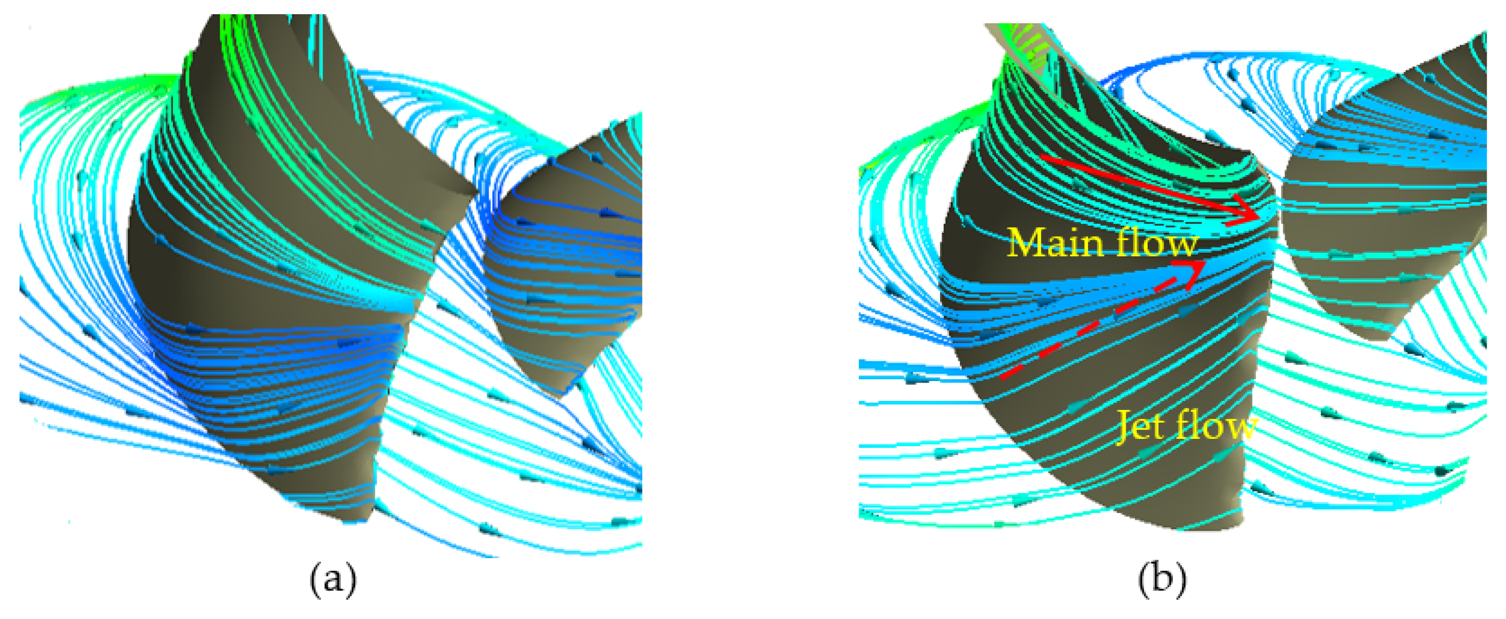
Figure 20.
Onset of hub corner separation depicted by limiting streamlines and total pressure.
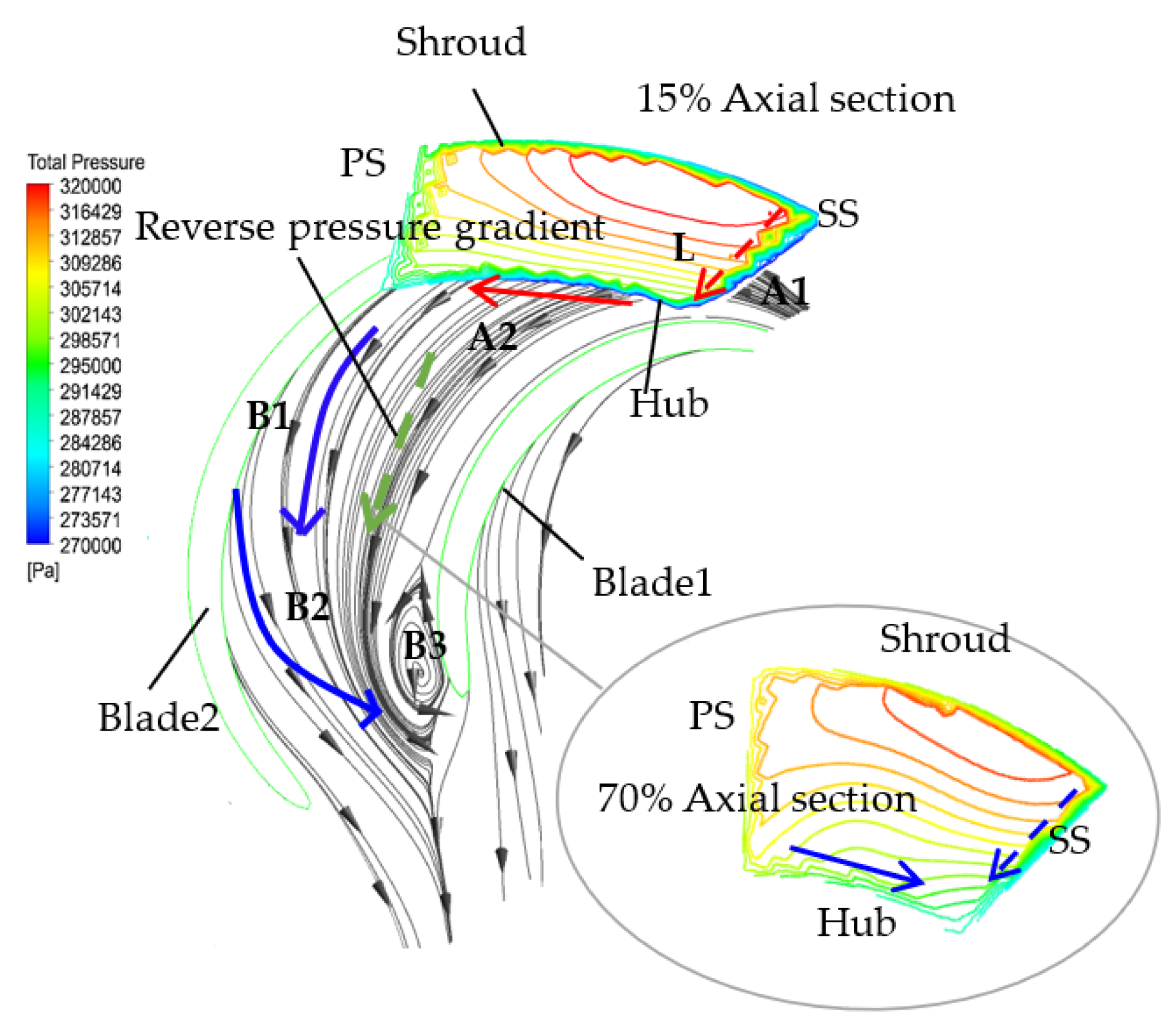
Figure 21.
Comparison of spanwise pressure difference from hub to shroud of suction surface.
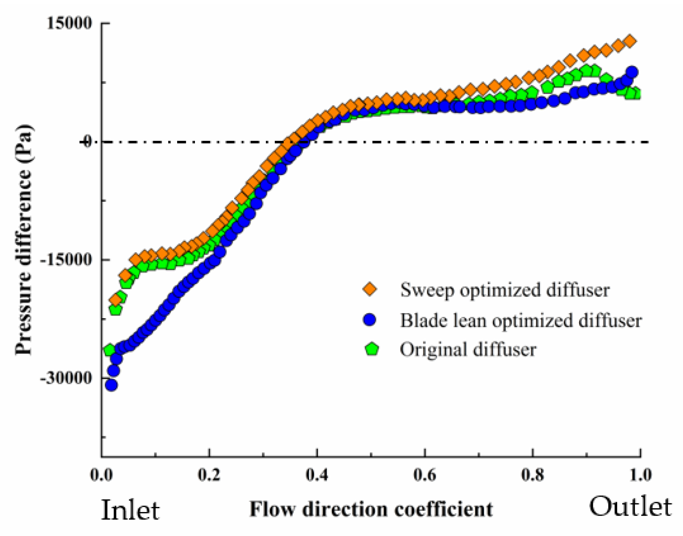
Figure 22.
Comparison of transverse pressure difference from PS to SS on hub surface.

Figure 23.
Static pressure comparison around shroud surface of diffuser.


Table 1.
The main structural parameters of the impeller.
| Parameters | Value |
|---|---|
| Blade number of impeller Z Diameter of inlet d1 (mm) Diameter of outlet d2 (mm) Width of blade outlet b2 (mm) Inlet angle of hub β1 (°) Outlet angle of hub β2 (°) | 7 97 134 20 28 34.2 |
Table 2.
The main structural parameters of the bowl diffuser.
| Parameters | Value |
|---|---|
| Blade number of diffuser Zd Diameter of outlet d4 (mm) Axial length e (mm) Inlet angle of hub β3 (°) Outlet angle of hub β4 (°) Wrap angle of hub ϕHub (°) Wrap angle of shroud ϕShroud (°) | 8 95 152 13.7 90 83 60 |
Table 3.
Influence of the grid number on accuracy.
| Parameter | N (×104×104) | H/m | ɳ/% |
|---|---|---|---|
| value | 302 410 553 680 837 988 | 33.20 33.04 32.86 32.74 32.69 32.70 | 95.04 95.00 94.91 94.88 94.88 94.88 |
Table 4.
Factors and levels for the central composite design.
| Levels | Factors | ||
|---|---|---|---|
| a0 | a1 | a2 | |
| −1.682 | −12.07 | −17.73 | 8.93 |
| −1 | −9 | −15 | 12 |
| 0 | −4.5 | −11 | 16.5 |
| 1 | 0 | −7 | 21 |
| 1.682 | 3.07 | −4.27 | 24.06 |
Table 5.
Factors and levels for the central composite design.
| Levels | Factors | ||
|---|---|---|---|
| b0 | b1 | b2 | |
| −1.682 | −3.05 | 10.61 | −55.36 |
| −1 | −1 | 13 | −54 |
| 0 | 2 | 16.5 | −52 |
| 1 | 5 | 20 | −50 |
| 1.682 | 7.05 | 22.39 | −48.64 |
Table 6.
Optimal solution of blade lean scheme.
| a0 | a1 | a2 | ɳ (%) | Cp | ζi | |
|---|---|---|---|---|---|---|
| Blade lean optimized diffuser | −4.4 | −12 | 15.16 | 95.1 | 0.1242 | 0.292 |
| Original diffuser | 5 | −5 | 0 | 94.8 | 0.1210 | 0.321 |
Table 7.
Optimal solution of sweep scheme.
| b0 | b1 | b2 | ɳ (%) | Cp | ζi | |
|---|---|---|---|---|---|---|
| Sweep optimized diffuser | 1.5 | 20 | −52 | 95.21 | 0.1245 | 0.279 |
| Original diffuser | 0 | 14 | −52.4 | 94.8 | 0.1210 | 0.321 |
Publisher’s Note: MDPI stays neutral with regard to jurisdictional claims in published maps and institutional affiliations. |
© 2021 by the authors. Licensee MDPI, Basel, Switzerland. This article is an open access article distributed under the terms and conditions of the Creative Commons Attribution (CC BY) license (https://creativecommons.org/licenses/by/4.0/).
Share and Cite
MDPI and ACS Style
Ning, C.; Cao, P.; Gong, X.; Zhu, R. Optimization of Sweep and Blade Lean for Diffuser to Suppress Hub Corner Vortex in Multistage Pump. Machines 2021, 9, 316. https://doi.org/10.3390/machines9120316
AMA Style
Ning C, Cao P, Gong X, Zhu R. Optimization of Sweep and Blade Lean for Diffuser to Suppress Hub Corner Vortex in Multistage Pump. Machines. 2021; 9(12):316. https://doi.org/10.3390/machines9120316
Chicago/Turabian StyleNing, Chao, Puyu Cao, Xuran Gong, and Rui Zhu. 2021. "Optimization of Sweep and Blade Lean for Diffuser to Suppress Hub Corner Vortex in Multistage Pump" Machines 9, no. 12: 316. https://doi.org/10.3390/machines9120316
Note that from the first issue of 2016, this journal uses article numbers instead of page numbers. See further details here.