Article

Determination of Heat Transfer Coefficient from Housing Surface of a Totally Enclosed Fan-Cooled Machine during Passive Cooling

1
Department of Electrical Machines and Apparatus, Riga Technical University, Kaļķu iela 1, LV-1658 Riga, Latvia
2
Department of Electrical Power Engineering and Mechatronics, Tallinn University of Technology, 19086 Tallinn, Estonia
3
CISE—Electromechatronic Systems Research Centre, University of Beira Interior, P 6201-001 Covilhã, Portugal
4
Department of Electrical Engineering and Automation, Aalto University, P.O. Box 15500, 00076 Aalto, Finland
*
Author to whom correspondence should be addressed.
Machines 2021, 9(6), 120; https://doi.org/10.3390/machines9060120
Submission received: 22 May 2021 / Revised: 11 June 2021 / Accepted: 16 June 2021 / Published: 18 June 2021
(This article belongs to the Special Issue Thermal Analysis of Electric Machine Drives)

Abstract

:
This paper presents the analytical calculation of the heat transfer coefficient of a complex housing shape of a Totally Enclosed Fan-Cooled (TEFC) industrial machine when it works below 20% of its nominal speed or close to stall. Therefore, passive cooling is dominant, and most of the heat is extracted by the combination of natural convection and radiation phenomena. Under these conditions, the area-based composite approach was used for the development of the analytical calculation method. A test rig using a TEFC Synchronous Reluctance Motor (SynRM) was constructed, and the collected experimental data was used to validate the proposed analytical method successfully.

1. Introduction

In a TEFC machine for variable speed drives, at low-speed performance or close to stall, the passive cooling is the dominant cooling [1,2]. Hence, heat fluxes are extracted from the housing to the ambient by the mixture of natural convection and radiation phenomena. In the thermal analysis of a TEFC motor, the accurate calculation of these parameters significantly impacts the thermal model accuracy. One of the standard methods to calculate these parameters is the analytical approach. In this approach, the convection and radiation are calculated using empirical correlations based on dimensionless numbers. Depending on the thermal analysis method, these phenomena are demonstrated by the coefficients used either directly or to calculate thermal resistance [3].
The most challenging parameters in determining the convection and radiation heat transfer are convection and radiation coefficients. This challenge is more severe for TEFC machines, including intricate and compound housing forms [4]. These coefficients depend on various factors, e.g., surface temperature, fluid, material properties, cooling methodology, surface shape, size, installation direction, and view factor [3]. Besides, semi-open fin channels on the outer circumferential of a TEFC housing are designed for the forced cooling purpose to provide the proper path for axial airflow generated by the fan [3]. Hence, they do not offer appropriate airflow passage into the fins depth [3]. Consequently, the fins structures are not constructed for effective natural cooling [2,5,6].
Calculating natural convection got less attention among the studies related to the thermal analysis of small to medium power ranges of industrial machines. Miller [7] presented one of the first studies in this field by applying a correlation for an electrical machine (EM) with unfinned cylindrical surfaces. This correlation entirely depends on the machine housing diameter and the temperature difference of the machine housing and the ambient heat. Staton [8] developed Miller’s study using the computational fluid dynamic (CFD) approach for several different machine housings, such as square housing, standard housing, and radial finned. He proposed the correlations for the mentioned bodies by defining new coefficients for the Miller correlation. Mellor [9] and Boglietti [10] demonstrated their thermal model for the TEFC machines and proposed the stator DC test to determine the thermal resistance between housing and ambient in natural cooling conditions. Later, Boglietti [2,11] proposed the empirical correlation to calculate the heat-transfer resistance from housing to ambient for the small and medium power ranges of the TEFC machine in the natural cooling conditions. Their correlation entirely depends on the housing surface area of the machine. Then, Staton [1,12], introduced the composite-based area correlation for calculating the convection coefficients. Moreover, he proposed the classical empirical correlations based on the dimensionless number to compute the convection coefficient [1,12].
However, radiation is the latest heat-transfer phenomenon whose effect has been implemented in thermal analysis and modeling of an EM [4]. In the past, most studies in EM thermal analysis neglected this phenomenon, based on the statement that the EM housing temperature was not reaching the level to provide heat transfer by the radiation [2,4,13]. Therefore, information and experimental results about radiation in the EM are scarce [2]. Boglietti et al. [13,14] presented one of the first studies investigating radiation impact on the heat transfer from an EM surface. They examined the effect of radiation heat transfer experimentally by developing a test rig. Since the heat transfer by radiation occurs in parallel by natural convection, they utilized a vacuum chamber to confine to heat transfer only by radiation. According to their findings, the amount of heat transfer by radiation during passive cooling is significant. Besides, other research studies on thermal engineering devices, such as heat sinks, demonstrated that in natural cooling terms, 20% to 40% of heat transfer occurs by radiation [15,16].
Consequently, the above hypothesis on neglecting the radiation phenomenon is incorrect and provides a significant error on EMs’ thermal analysis. However, utilizing this hypothesis during forced cooling does not lead to substantial errors and it can still be implemented. This coefficient is calculated easily for smooth surfaces. However, it becomes critical for finned housing. In this case, the view factor is the crucial parameter, involving complex mathematical calculations.
This paper aims to provide a comprehensive study to enhance knowledge in calculating the heat-transfer coefficient of a TEFC housing of EMs in passive cooling. The research focuses on existing challenges and problems of developing the analytical method using the area-based composite method. The main objective is to propose an analytical approach to determine the heat-transfer coefficient (radiation and convection coefficients) of a TEFC housing in natural cooling. Furthermore, it offers a simplified assumption to reduce the mathematical complexity of the view factor calculation.
For the research purposes, the analytical method described in this study was applied to a four-pole, 10 kW, 400 V, 50 Hz, TEFC SynRM with ‘F’ insulation class. Figure 1 illustrates a CAD drawing of the SynRM. Firstly, the analytical calculation approach for calculating the convection and radiation coefficients is described in detail. Next, a test bench was set up, and measurements were conducted. Then, the experimental data were compared to the corresponding results obtained through the proposed analytical method to validate the analytical process.
Table 1 shows the characteristic data of the machine housing’s fin section at the axial length of 222.5 mm and a diameter of 230 mm.

2. Analytical Background of Heat-Transfer Coefficient

The crucial parameter in calculating the heat transfer from the machine housing to the ambient is the heat-transfer coefficient (h0). This coefficient indicates the effect of the heat transfer by radiation and the convection phenomena, and is described as:
h 0 = h c + h r ,
where hc and hr are convection and radiation coefficients (W/m2/K), respectively.
Therefore, at first, calculating the convection coefficient of the actual frame of a TEFC EM using an analytical approach by the area-based composite method was considered. Then, the study was extended to determine the radiation coefficient from the actual frame of a TEFC.

2.1. Natural Convection

The convection phenomenon is a heat transfer between solid surfaces and fluid due to the fluid motion [1]. During passive cooling (natural convection), the fluid motion process occurs by the buoyancy forces according to the density difference of hot and cold fluid molecules.
One of the standard methods to calculate the convection coefficient is utilizing empirical correlations. The empirical correlations are defined by the dimensionless number, e.g., Nusselt number (Nu), Rayleigh (Ra), Grashof (Gr), Prandtl (Pr), and Reynolds (Re) numbers [17]. In this manner, the convection coefficient is defined as [1]:
h c = Nu · k L .
where k is fluid thermal conductivity (W/m/°C), and L is the characteristic length of the surface (m).
According to (2), the only unknown parameter is the Nusselt number, and its typical form for the natural convection is defined as [1]:
Nu = a ( Gr · Pr ) b ,
where a and b are constants, Grashof (Gr), Prandtl (Pr) numbers are calculated, respectively, as [1]:
Gr = β g Δ T ρ 2 L 3 μ 2 ,
Pr = c p μ k ,
where β is the cubical expansion coefficient (1/K), g is the gravitational acceleration (m/s2), ΔT is the temperature difference between the surface and the ambiance (°C), ρ is the fluid density (kg/m3), μ is the dynamic fluid viscosity (kg/s/m), and cp is the fluid specific heat capacity (kJ/kg/°C).
In the analytical calculation of the natural convection coefficient of a TEFC EM, we are faced with a complex and compound housing structure for which there is no single correlation to demonstrate the Nusselt number. Therefore, the complex and compound housing structure is divided into several simpler shapes with known correlation for calculating the Nusselt numbers. Then, from these values and using (2), the convection coefficient of each body is obtained. Finally, the total convection coefficient of a TEFC housing is determined by utilizing the area-based composite technique [1]. A positive aspect of this technique is that the total convection coefficient is more similar to the dominant shape’s convection coefficient [2]. Furthermore, the EM installation direction (vertical or horizontal) is essential for analyzing natural convection. This study considers the analytical calculation for the EM, which is installed in the horizontal direction.
Figure 2 shows the schematic of a TEFC housing. The machine housing is divided into various primary forms with known empirical correlations as follows:
  • Horizontal cylinder as a fin channel base.
  • Horizontal U-shaped fin channels as semi-open fin channels on the top and bottom of the housing.
  • Horizontal flat plate (upper and lower) as semi-open fin channels on the side of the housing.
  • Horizontal and vertical flat plates as fin tips; and
  • Vertical plates as end caps.
Therefore, the empirical correlation for basic shapes and more complex shapes such as horizontal U-shaped channels are described hereafter.
Natural convection from a horizontal flat plate:
As Figure 3 shows, the placement of the horizontal hot plate (upper face and lower face) plays a decisive role in selecting the correlation [18]. Accordingly, the empirical correlations for the horizontal flat plate, which is placed in the upper face for the laminar (105 < Gr·Pr < 108) and turbulent mode (Gr·Pr > 108) are, respectively, as [19,20]:
Nu = 0.54 ( Gr · Pr ) 0.25 ,
Nu = 0.15 ( Gr · Pr ) 0.33 .
Finally, the correlation of a horizontal hot flat plate in the downside direction is defined as:
Nu = 0.27 ( Gr · Pr ) 0.25 ,
Natural convection from a vertical flat plate:
The Nusselt numbers in the case of a vertical flat plate for laminar (104 < Gr·Pr < 109) and turbulent (Gr·Pr > 109) modes are defined based on McAdams’ research, respectively, as [20]:
Nu = 0.59 ( Gr · Pr ) 0.25 ,
Nu = 0.10 ( Gr · Pr ) 0.33 .
Natural convection from a horizontal cylinder:
The empirical correlations for the horizontal cylinder in the laminar (104 < Gr·Pr < 109) and turbulent (Gr·Pr > 109) are, respectively, [20]:
Nu = 0.525 ( Gr · Pr ) 0.25 ,
Nu = 0.129 ( Gr · Pr ) 0.33 .
Natural convection from a horizontal fin channel:
Figure 4 presents the schematic of the horizontal fin channels on the TEFC housing. Jones and Smith’s correlation is one of the most accurate correlations determining the Nusselt number of horizontal fin channels in the natural cooling conditions [21,22]. Their correlation does not depend on the fin size [21,22]. They assumed that the horizontal fin channels have a U-shaped format and, based on this assumption, they developed the below correlation with fin space (S) as the characteristic length [21,22]:
Nu = 0.00067   · Gr · Pr · { 1 e ( 7640 Gr · Pr ) 0.44 }   1.7 .

2.2. Radiation

Radiation is counted as an electromagnetic phenomenon, which transfers the heat fluxes by electromagnetic waves [24,25]. Besides, there is no need for intermediaries to extract the heat by this phenomenon, even it happens in a vacuum condition [24]. The heat-transfer rate of this phenomenon is directly proportional to the body’s absolute temperature [25].
It is hard to determine the radiation coefficient experimentally since it is a complex process. Moreover, radiation and convection coincide, and are in parallel with each other. Separating these two phenomena from each other is complex. Therefore, the standard method is to add the convection and the radiation coefficients together as the heat-transfer coefficient in the thermal analysis.
The analytical correlation to calculate the radiation coefficient (hr) is defined as [25,26,27]:
h r = ε σ F T 1 4 T 2 4 T 1 T 2 = ε σ F ( T 1 + T 2 ) ( T 1 2 + T 2 2 )
where ε is the relative emissivity, σ is the Stefan-Boltzmann constant [5.67 × 10⁻⁸ (W/m2/K4)], F is the view factor, and T1 and T2 are the radiating surface temperature and absorbing surfaces temperature (K), respectively.
However, the evaluation of this coefficient for a TEFC machine is more complicated than for a machine with a smooth housing structure. According to (14), the most challenging parameter in calculating the radiation coefficient is the view factor which consists of severe and complex mathematical and analytical analyses. Staton [21] proposes the hypothesis to reduce the complexity and mathematical analysis of the view factor. According to his idea, the view factor of a body with a clear view of ambient equals one, and for other bodies with no clear view it equals zero. Basically, in the TEFC housing, heat transfer by radiation is confined to the fin base, fin tips, and end caps [28]. In this paper, the same hypothesis is utilized to calculate the radiation coefficient.

3. Analytical Analysis Approach

As aforementioned, in this study the machine is installed in a horizontal direction. As the fin’s axial length, fin spaces, and fins height are various, the mean values of each parameter are calculated and presented in Table 1.
The TEFC housing is a compound structure, and there is no single correlation to evaluate the convection and radiation coefficient of the entire housing. Hence, as Table 2 shows, the housing is divided into several primary forms with known correlation, such as horizontal U-shaped fin channels, horizontal flat plate, vertical flat, etc.
Finally, the total heat-transfer coefficient (h0) of TEFC housing is calculated by the area-based composite method as:
h 0 = h 1 A 1 + h 2 A 2 + A T
where h1 is the heat transfer coefficient from primary form one (W/m2/K), A1 is the primary form one area (m2), h2 is the heat transfer coefficient primary form two (W/m2/K), A2 is the primary form two area (m2), and AT is the total TEFC housing surface (m2).

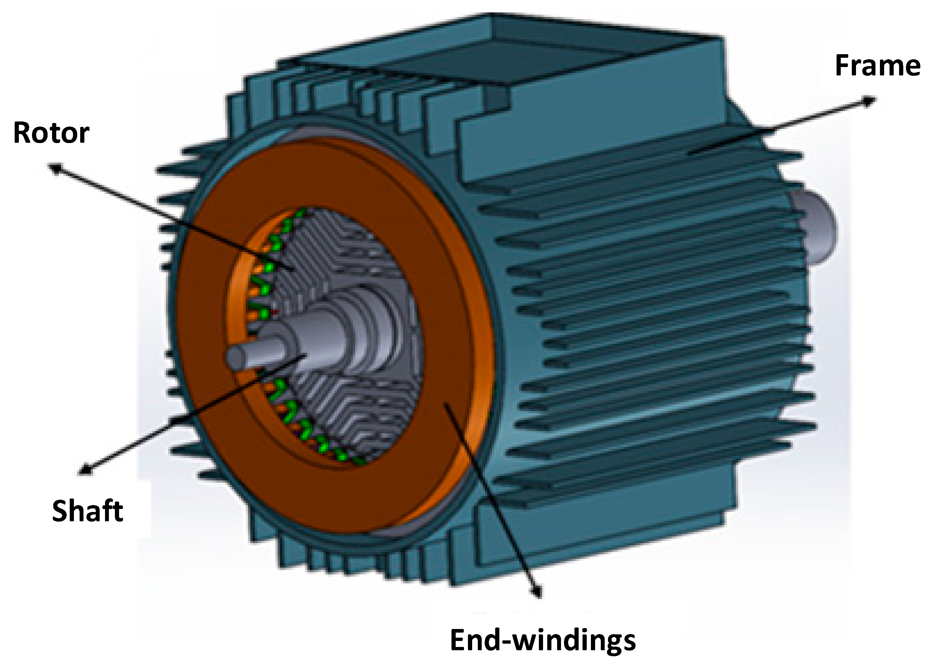
4. Experimental Methodology and Analysis Method of Experimental Data

This section mainly focuses on experimental verifications and validation of the analytical method performance for predicting the heat transfer of a TEFC housing machine in passive cooling conditions. Therefore, in the first part of this section, the experimental methodology and technique are described. Then, the analysis method of experimental data is discussed. Finally, the accuracy of experimental data is determined using uncertainty analysis.

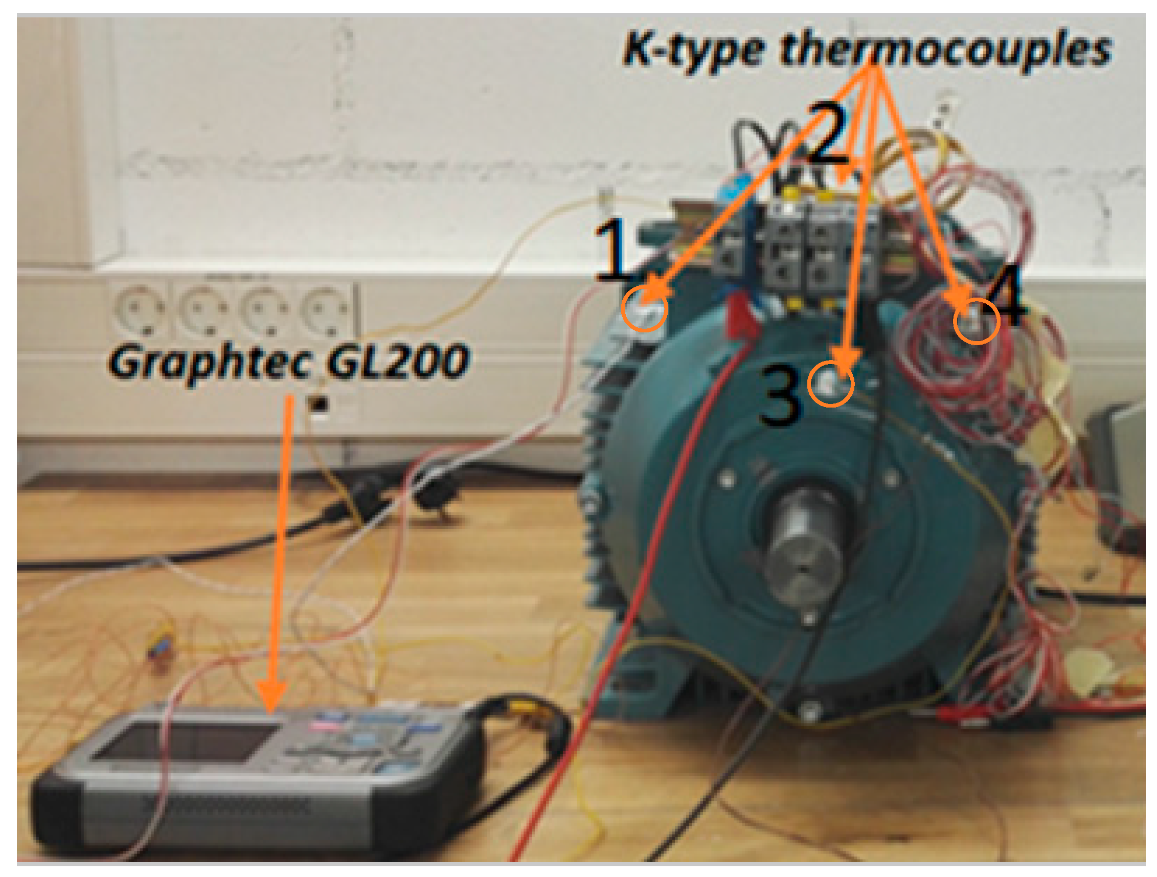
4.1. Experimental Methodology

The DC stator test is the standard experimental technique to evaluate the heat-transfer coefficient of a machine housing in passive (natural) cooling [29]. In this technique, the EM losses are limited to the stator copper losses and easily determined [30,31]. But the drawback of this technique is the long-term test period, as an EM may take up to eight hours to reach its steady-state thermal condition [30].
For this purpose, the EM stator windings were connected in series and connected to the DC power supply to provide the required DC power. During the test, the values of injected current, voltage, surface temperature of the TEFC housing, and ambient temperature were collected. According to Figure 5, four K-type thermocouples were installed in the various parts of the EM housing to measure the temperature of different housing parts. Moreover, another K-type thermocouple was used to measure the ambient temperature. All the temperature measurement data were collected by the data acquisition system Graphtech GL200. Also, the mean housing temperature equals the average temperature collected by these four thermocouples in the machine housing. The experiment was conducted with five different input currents, and the investigation for each input current was carried out until the system reached its thermal equilibrium.

4.2. Collected Data Analysis Approach

After collecting the data, the heat-transfer coefficient was obtained from the experimental data. In the first step, the total heat (QT) was determined. In the DC test, the total heat equalled DC stator copper losses, which was easily determined by the collected value of current and voltage as:
Q T = V · I
where V and I are the input voltage and current, respectively.
By knowing the values of the total heat (QT), surface TEFC housing temperature (Ts), and ambient temperature (Ta), the total heat-transfer coefficient (h0) is computed as [26,27]:
h 0 = Q T ( T s T a ) A T ,

4.3. Uncertainty Analysis

The accuracy of the experimental data directly depends on the accuracy of the measurement equipment. The uncertainty analysis is the approach to find the accuracy of the measurement data based on measurement equipment precision. In the experiment, TTi QPX1200S was used to measure the voltage and current with the measurement accuracy of 0.1% and 0.3%, respectively. Also, the measurement accuracy of K-type thermocouples was 0.75%.
At first, the accuracy heat loss (wQT) was determined as:
w Q T = [ ( Q T V · w V ) 2 + ( Q T I · w I ) 2 ] 1 / 2
where wV and wI are the measurement accuracy of voltage and current, respectively.
Finally, the uncertainty value of the heat transfer coefficient was defined as:
w h o = [ ( h o Q T · w Q T ) 2 + 2 · ( h o T · w T ) 2 ] 1 / 2
where wT is the measurement accuracy of K-type thermocouple.

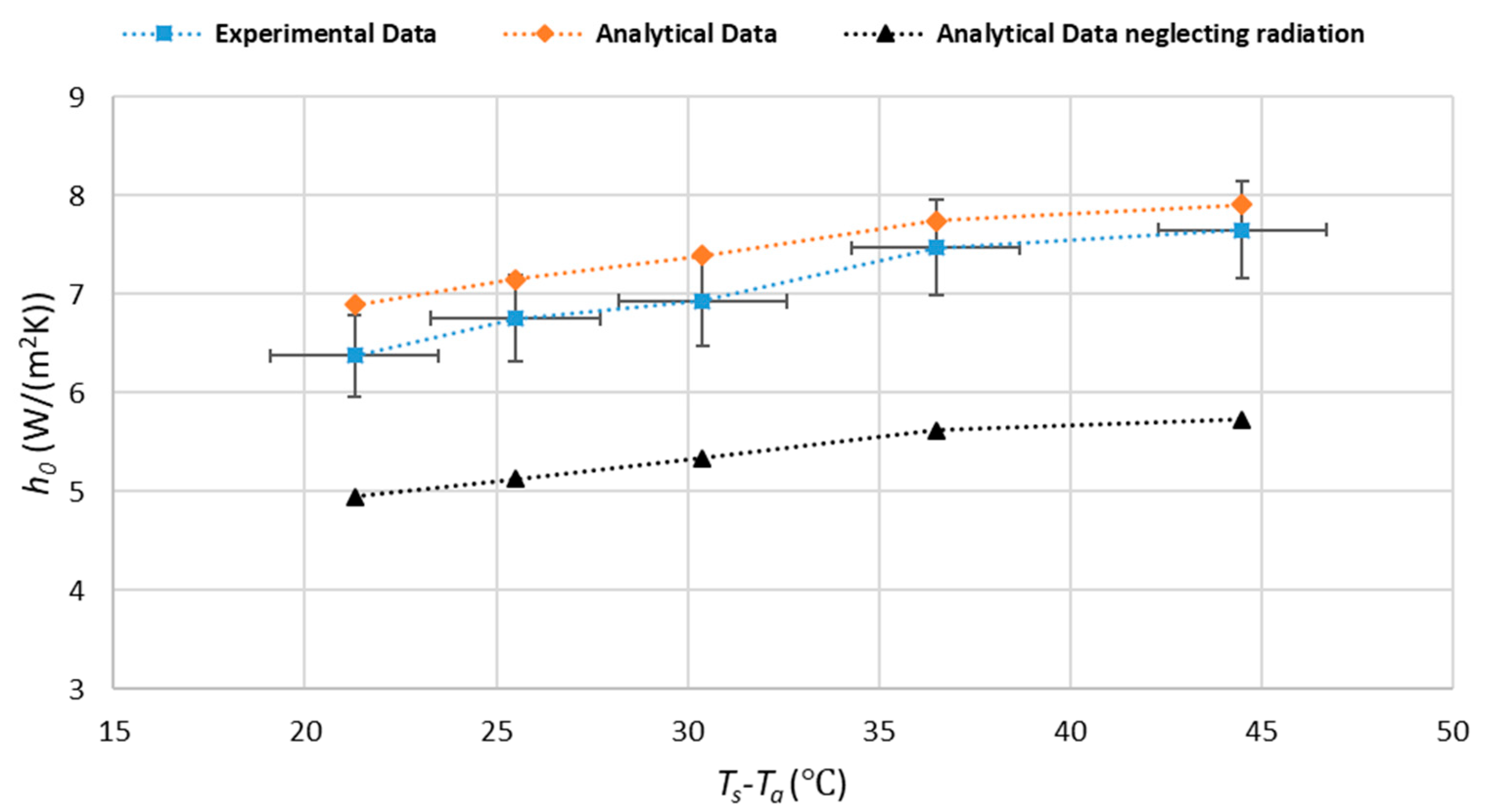
5. Validation and Discussion

The experimental phase is accomplished to validate and check the accuracy of the analytical analysis approach to calculate the heat-transfer coefficient of a TEFC EM in natural cooling.
Firstly, in the experimental stage, the heat power (QT) value was calculated by (16). Then, the convection coefficient value (h0) was determined using (17). In the analytical calculation stage, the TEFC housing was divided into several primary shapes (Table 2), and the convection coefficient of each primary body was calculated using appropriate correlations. For the radiation calculation, the hypothesis proposed by Staton was used to determine the view factor. Finally, using the area-based composite approach, the total heat transfer coefficient was calculated (15).
Table 3 and Table 4 show the analytical analysis results of the heat-transfer coefficient (h0). Table 3 shows the analytical results, including the radiation phenomenon, and Table 4 shows the analytical results, which excluded the radiation phenomenon. Finally, Table 5 demonstrates the experimental results of the DC stator test.
Figure 6 shows the analytical and experimental results, which are plotted versus the TEFC housing surface and ambient temperature difference to increase the resolution and simplify the comparison. The uncertainty analysis values are demonstrated as error bars in the experimental data presented in Figure 6. Based on uncertainty analysis, the maximum uncertainty in the experimental results of heat-transfer coefficient is about 6.2%, and the temperature measurement is about ±2 °C.
Accordingly, the mean relative difference of the analytical data, including the radiation phenomenon and the experimental data, is about 5.5%. The maximum mean difference is 8.2%, which occurs at the low temperature of TEFC housing. According to Figure 6, the relative difference of analytical and experimental data reduces by increasing the surface temperature. As a result, the accuracy of the analytical method in calculating the heat-transfer coefficient increases by enhancing the housing temperature. Therefore, the accuracy of the analytical approach is higher at high housing temperatures. Consequently, it predicts the heat transfer coefficient more accurately at higher housing temperatures.
Furthermore, comparing the analytical data, including radiation and excluding radiation, proves that ignoring the radiation phenomenon is not a correct assumption in passive cooling. It leads to a significant difference in final results. In this study, neglecting the radiation shows about 30% error in the value of the heat-transfer coefficient.
The radiation phenomenon transfers around 28% of the total heat. Moreover, implementing the Staton hypothesis in calculating the radiation coefficient does not significantly affect the final value of the heat-transfer coefficient. Hence, using this hypothesis is beneficial to save computational time and to simplify the mathematical calculation.

6. Conclusions

This study has illustrated the analytical approach to predict the heat-transfer coefficient of a TEFC housing in natural cooling conditions. This analytical approach is developed using area-based composite theory. Moreover, this paper proposed the simplifying hypothesis to reduce computation time and mathematical calculation of the view factor in the radiation coefficient calculation with great accuracy.
According to the initial results, the analytical approach can successfully predict the heat-transfer coefficient with a low mean relative difference of 5.5% compared to the experimental results. Furthermore, the accuracy of this approach is enhanced by increasing the housing temperature, so it provides more accurate predictions for higher surface temperature.
According to initial results, approximately 30% of heat is transferred by the radiation phenomenon. Consequently, omitting this phenomenon in calculating the heat-transfer coefficient and confining the heat transfer to natural convection leads to a significant error. Moreover, calculating the view factor and restricting the radiation from specific surfaces does not demonstrate a substantial error in the final results. As a result, the simplifying assumption in radiation calculation offers fast and easy calculation. To conclude, the proposed analytical calculation approach has excellent potential to predict the convection coefficients in passive heat extraction conditions.

Author Contributions

Conceptualization, P.S.G., A.P., A.K., A.B. and A.J.M.C.; methodology, P.S.G., A.P., A.K.; validation, P.S.G., A.K.; data curation, P.S.G. and B.A.; writing—original draft preparation, P.S.G.; writing—review and editing, A.J.M.C., A.B., T.V.; visualization, T.V., H.T. and B.A.; supervision, A.P. All authors have read and agreed to the published version of the manuscript.

Funding

This work was supported by the European Regional Development Fund within the Activity 1.1.1.2 “Postdoctoral Research Aid” of the Specific Aid Objective 1.1.1 “To increase the research and innovative capacity of scientific institutions of Latvia and the ability to attract external financing, investing in human resources and infrastructure” of the Operational Program “Growth and Employment” (No.1.1.1.2/VIAA/3/19/501). This work was also supported by the European Regional Development Fund (ERDF) through the Operational Program for Competitiveness and Internationalization (COMPETE 2020), under Project POCI-01-0145-FEDER-029494, and by National Funds through the FCT—Portuguese Foundation for Science and Technology, under Projects PTDC/EEI-EEE/29494/2017, UIDB/04131/2020, and UIDP/04131/2020.

Institutional Review Board Statement

Not applicable.

Informed Consent Statement

Not applicable.

Data Availability Statement

Not applicable.

Conflicts of Interest

The authors declare no conflict of interest.

References

  1. Staton, D.A.; Cavagnino, A. Convection Heat Transfer and Flow Calculations Suitable for Electric Machines Thermal Models. IEEE Trans. Ind. Electron. 2008, 55, 3509–3516. [Google Scholar] [CrossRef] [Green Version]
  2. Boglietti, A.; Cavagnino, A.; Staton, D. Determination of Critical Parameters in Electrical Machine Thermal Models. IEEE Trans. Ind. Appl. 2008, 44, 1150–1159. [Google Scholar] [CrossRef]
  3. Shams Ghahfarokhi, P.; Kallaste, A.; Vaimann, T.; Belahcen, A. Thermal Analysis of Totally Enclosed Fan Cooled Synchronous Reluctance Motor-state of art. In Proceedings of the 45th Annual Conference of the IEEE Industrial Electronics Society (IECON), Lisbon, Portugal, 14–17 October 2019; pp. 1–5. Available online: https://ieeexplore.ieee.org/document/8927706 (accessed on 12 December 2019).
  4. Ghahfarokhi, P.S.; Kallaste, A.; Podgornovs, A.; Belahcen, A.; Vaimann, T. Development of analytical thermal analysis tool for synchronous reluctance motors. IET Electr. Power Appl. 2020, 14, 1828–1836. [Google Scholar] [CrossRef]
  5. Rosu, M.; Zhou, P.; Lin, D.; Ionel, D.; Popescu, M.; Blaabjerg, F.; Rallabandi, V.; Staton, D. Multiphysics Simulation by Design for Electrical Machines, Power Electronics, and Drives; Wiley: Hoboken, NJ, USA, 2018. [Google Scholar]
  6. Popescu, M.; Staton, D.; Dorrell, D.; Marignetti, F.; Hawkins, D. Study of the thermal aspects in brushless permanent magnet machines performance. In Proceedings of the 2013 IEEE Workshop on Electrical Machines Design, Control and Diagnosis (WEMDCD), Paris, France, 11–12 March 2013; pp. 60–69. [Google Scholar] [CrossRef]
  7. Miller, T.J.E. Switched Reluctance Motors and Their Control; Oxford University Press: Oxford, UK, 1993; Volume 31. [Google Scholar]
  8. Staton, D.A.; So, E. Determination of optimal thermal parameters for brushless permanent magnet motor design. In Proceedings of the Conference Record of 1998 IEEE Industry Applications Conference. Thirty-Third IAS Annual Meeting, St. Louis, MO, USA, 12–15 October 1998; Volume 1, pp. 41–49. [Google Scholar] [CrossRef]
  9. Mellor, P.; Roberts, D.; Turner, D. Lumped parameter thermal model for electrical machines of TEFC design. IEE Proc. B Electr. Power Appl. 1991, 138, 205–218. [Google Scholar] [CrossRef]
  10. Boglietti, A.; Cavagnino, A.; Lazzari, M.; Pastorelli, M.A. A simplified thermal model for variable-speed self-cooled industrial induction motor. IEEE Trans. Ind. Appl. 2003, 39, 945–952. [Google Scholar] [CrossRef]
  11. Boglietti, A.; Cavagnino, A.; Staton, D.; Shanel, M.; Mueller, M.; Mejuto, C. Evolution and Modern Approaches for Thermal Analysis of Electrical Machines. IEEE Trans. Ind. Electron. 2009, 56, 871–882. [Google Scholar] [CrossRef] [Green Version]
  12. Staton, D.; Boglietti, A.; Cavagnino, A. Solving the More Difficult Aspects of Electric Motor Thermal Analysis in Small and Medium Size Industrial Induction Motors. IEEE Trans. Energy Convers. 2005, 20, 620–628. [Google Scholar] [CrossRef] [Green Version]
  13. Boglietti, A.; Cavagnino, A.; Parvis, M.; Vallan, A. Evaluation of radiation thermal resistances in industrial motors. IEEE Trans. Ind. Appl. 2006, 42, 688–693. [Google Scholar] [CrossRef] [Green Version]
  14. Boglietti, A.; Vallan, A. Measurement of Housing Thermal Resistances in Industrial Motors. In Proceedings of the IEEE Instrumentation and Measurement Technology Conference, Sorrento, Italy, 24–27 April 2006; pp. 1321–1325. [Google Scholar] [CrossRef]
  15. Rao, V.D.; Naidu, S.; Rao, B.G.; Sharma, K.V. Heat transfer from a horizontal fin array by natural convection and radiation—A conjugate analysis. Int. J. Heat Mass Transf. 2006, 49, 3379–3391. [Google Scholar] [CrossRef]
  16. Ahmadi, M.; Mostafavi, G.; Bahrami, M. Natural convection from rectangular interrupted fins. Int. J. Therm. Sci. 2014, 82, 62–71. [Google Scholar] [CrossRef]
  17. Gai, Y.; Kimiabeigi, M.; Chong, Y.C.; Widmer, J.D.; Deng, X.; Popescu, M.; Goss, J.; Staton, D.A.; Steven, A. Cooling of Automotive Traction Motors: Schemes, Examples, and Computation Methods. IEEE Trans. Ind. Electron. 2019, 66, 1681–1692. [Google Scholar] [CrossRef] [Green Version]
  18. Cengel, Y.A. Heat Transfer: A Practical Approach; McGraw-Hill: New York, NY, USA, 2004. [Google Scholar]
  19. Bejan, A.; Kraus, A.D. Heat Transfer Handbook; John Wiley & Sons: Hoboken, NJ, USA, 2003. [Google Scholar]
  20. Shams Ghahfarokhi, P.; Kallaste, A.; Vaimann, T.; Belahcen, A. Natural convection from flat side’s of coil system. In Proceedings of the 19th International Scientific Conference on Electric Power Engineering (EPE), Brno, Czech Republic, 16–18 May 2018; pp. 1–5. [Google Scholar] [CrossRef]
  21. Jones, C.D.; Smith, L.F. Optimum Arrangement of Rectangular Fins on Horizontal Surfaces for Free-Convection Heat Transfer. J. Heat Transf. 1970, 92, 6–10. [Google Scholar] [CrossRef]
  22. Shams Ghahfarokhi, P.; Kallaste, A.; Vaimann, T.; Rassolkin, A.; Belahcen, A. Determination of natural convection heat transfer coefficient over the fin side of a coil system. Int. J. Heat Mass Transf. 2018, 126, 677–682. [Google Scholar] [CrossRef]
  23. Motor-CAD Software by Motor Design—EMag, Therm and Lab. Available online: https://www.motor-design.com/motor-cad-software/ (accessed on 17 June 2021).
  24. Pyrhonen, J.; Jokinen, T.; Hrabovcová, V. Design of Rotating Electrical Machines; Wiley: Hoboken, NJ, USA, 2008. [Google Scholar]
  25. Popescu, M.; Staton, D.A.; Boglietti, A.; Cavagnino, A.; Hawkins, D.; Goss, J. Modern Heat Extraction Systems for Power Traction Machines—A Review. IEEE Trans. Ind. Appl. 2016, 52, 2167–2175. [Google Scholar] [CrossRef]
  26. Markovic, M.; Saunders, L.; Perriard, Y. Determination of the Thermal Convection Coefficient for a Small Electric Motor. In Proceedings of the Conference Record of the 2006 IEEE Industry Applications Conference Forty-First IAS Annual Meeting, Tampa, FL, USA, 8–12 October 2006; Volume 1, pp. 58–61. [Google Scholar] [CrossRef]
  27. Meksi, O.; Vargas, A.O. Numerical and experimental determination of external heat transfer coefficient in small TENV electric machines. In Proceedings of the 2015 IEEE Energy Conversion Congress and Exposition (ECCE), Montreal, QC, Canada, 20–24 September 2015; pp. 2742–2749. [Google Scholar] [CrossRef]
  28. Shams Ghahfarokhi, P.; Kallaste, A.; Podgornovs, A.; Belahcen, A.; Vaimann, T.; Asad, B. Determination of heat transfer coefficient of finned housing of a TEFC variable speed motor. Electr. Eng. 2020, 103, 1–9. [Google Scholar] [CrossRef]
  29. Boglietti, A.; Cavagnino, A.; Staton, D.A. Thermal analysis of TEFC induction motors. In Proceedings of the 38th IAS Annual Meeting on Conference Record of the Industry Applications Conference, Salt Lake City, UT, USA, 12–16 October 2003; Volume 2, pp. 849–856. [Google Scholar] [CrossRef]
  30. Boglietti, A.; Cavagnino, A.; Staton, D. TEFC Induction Motors Thermal Models: A Parameter Sensitivity Analysis. IEEE Trans. Ind. Appl. 2005, 41, 756–763. [Google Scholar] [CrossRef] [Green Version]
  31. Shams Ghahfarokhi, P.; Kallaste, A.; Vaimann, T.; Rassolkin, A.; Belahcen, A. Steady-State Thermal Model of a Synchronous Reluctance Motor. In Proceedings of the 2018 IEEE 59th International Scientific Conference on Power and Electrical Engineering of Riga Technical University (RTUCON), Riga, Latvia, 12–13 November 2019; pp. 1–5. [Google Scholar] [CrossRef] [Green Version]
Figure 1. Structure of the transverse-laminated SynRM.
Machines 09 00120 g001
Figure 2. Division of the TEFC housing into several basic shapes.
Machines 09 00120 g002
Figure 3. Two placements of a horizontal hot plate, (a) facing up, and (b) facing down.
Machines 09 00120 g003
Figure 4. Horizontal fin channel schematic [23].
Machines 09 00120 g004
Figure 5. Passive cooling test setup.
Machines 09 00120 g005
Figure 6. Analytical and experimental results of the heat-transfer coefficient versus temperature difference of TEFC housing and ambient.
Machines 09 00120 g006
Table 1. Characteristic data of the fin section.
Mean Fin’s Length
(mm)
Mean Fin’s Height
(mm)
Mean Fin’s Spacing
(mm)
Number of
Fins
Fins on the top of the housing34.3824.3711.8612
Fins on the underside of the housing184.2524.3711.8612
Fins on the sides of the housing180.7524.839.7030
Table 2. Segregation of the compound structure of TEFC housing.
ComponentConvection CorrelationEmissivityView FactorArea
(m2)
Fin baseHorizontal cylinder0.810.0918
Fins on top of
the housing
Horizontal fin channel0.800.0201
Fins on undersides
of the housing
Horizontal fin channel0.800.1078
Fins on the sides
of the housing
Horizontal flat plate (upper and lower faces)0.800.2692
Fin tipsHorizontal and vertical flat plate0.810.0209
End capsVertical flat plate0.810.0831
Table 3. Analytical analysis results including the radiation phenomenon.
V
(v)
Ts
(°C)
Ta
(°C)
h0
(W/m2/K)
154220.56.91
174721.67.14
1951.520.87.39
226121.67.78
2564.521.27.93
Table 4. Analytical analysis results excluding the radiation phenomenon.
V
(v)
Ts
(°C)
Ta
(°C)
h0
(W/m2/K)
154220.54.95
174721.65.13
1951.520.85.34
226121.65.62
2564.521.25.73
Table 5. Experimental results.
V
(v)
I
(A)
Ts
(°C)
Ta
(°C)
QT
(W)
h0
(W/m2/K)
156.454220.596.756.37
177.124721.6121.046.76
197.7951.520.8148.016.93
228.716121.6191.627.47
259.5764.521.2239.257.65
Publisher’s Note: MDPI stays neutral with regard to jurisdictional claims in published maps and institutional affiliations.

