High-Performance Ni-SiC Coatings Fabricated by Flash Heating


J. Mike Walker ’66 Department of Mechanical Engineering, Texas A&M University, College Station, TX 77843-3123, USA
*
Author to whom correspondence should be addressed.
Lubricants 2022, 10(3), 42; https://doi.org/10.3390/lubricants10030042
Submission received: 21 January 2022
/
Revised: 5 March 2022
/
Accepted: 10 March 2022
/
Published: 14 March 2022
(This article belongs to the Special Issue Special Issue in Elastohydrodynamics: Remembering Ramsey Gohar)
Abstract
:In this research, a novel flash heating coating application technique was utilized to create Ni-SiC coatings on carbon steel substrates with SiC contents much higher than is achievable using certain conventional coating techniques. Hardness profiles showed that the coatings improved the substrate by as much as 121%, without affecting the substrate. Tribotests showed that the wear performance was improved by as much as 4.7 in terms of the wear rate (mm3/N·m) for the same coating when using an Al2O3 counterpart. Pure SiC coatings as a reference were also fabricated. However, the SiC coatings experienced elemental diffusion of Fe from the carbon steel substrate into the coating during fabrication. This occurred due to the increased heat input required for pure SiC to fuse to the substrate compared to the Ni-SiC coatings and resulted in decreased tribological performance. Diffusion of Fe into the coating weakened the coating’s hardness and reduced the resistance to wear. It was concluded that ceramic–metallic composite coatings can successfully be fabricated utilizing this novel flash heating technique to improve the wear resistance of ceramic counterparts.
1. Introduction
In various industrial applications, the typically used materials are not suitable for the environment they are placed in. For these situations, coatings are needed to supplement the surface properties of the base materials used. There are several advantages of using coatings, including reducing wear, friction, and corrosion by protecting the underlying substrate [1,2,3,4,5]. Coatings can also increase the hardness and fatigue resistance by preventing deformation [6,7,8]. By applying a coating, the favorable surface properties of the coating replace the underwhelming properties of the substrate. Coatings can be applied through several processes, such as electrocodeposition [9], electrophoretic deposition [10], and thermal spraying [11]. For these reasons, coatings are recommended for a wide range of applications [12,13,14,15,16,17,18].
Ni-SiC coatings represent some of the promising coatings for use in various demanding applications. The characteristics of wear resistance [19], hardness [20,21], and corrosion resistance [22,23] have been researched for Ni-SiC coatings. Since SiC is a second-phase material in such coatings, with the Ni acting as the matrix, the SiC particles tend to cause lattice distortions and reduce the crystal growth of the Ni, improving a variety of tribological characteristics [24,25,26,27,28,29]. Ni-SiC coatings have been shown to have higher hardness than pure Ni [25,30], can improve corrosion resistance when used coatings for certain materials such as magnesium alloys [3], and have better wear resistance than pure Ni [31]. Ni-SiC coatings are used in mechanical, chemical, petroleum, and protection applications [32], especially in the automotive [33] and manufacturing [34] industries. In both industries, equipment can vibrate, which can cause fretting, mean a coating such as Ni-SiC is often necessary. Some industrial applications also require operation in saline environments, which can cause corrosion damage. The combination of these factors can create an environment apt for the complex mechanisms of tribocorrosion [35], which Ni-SiC coatings are particularly well suited to handle [33].
There are several techniques used to produce ceramic–metallic composite coatings, such as Ni-SiC coatings. One of the more common methods is electrochemical deposition, often shortened to electrodeposition. In this method, an electrolyte is prepared with reagents added to distilled [36] or deionized [37] water. An electric field is applied to the electrolyte, causing the coating to deposit onto the substrate [38]. For Ni-SiC coatings, the SiC particles are immersed in the bath fluid [39]; however, there are some challenges in using this method. SiC particles dispersed in the bath fluid can cause uneven deposition in the coating, and the maximum SiC content depends on the SiC particle size [31]. Additionally, SiC particles are not easily embedded in coatings, meaning coatings typically have a low concentration of SiC particles. This issue can only be overcome using a surfactant or dispersant. These SiC particles can also be polished to prevent agglomeration and compaction [40]. Another disadvantage of this method is that the hardness of the coatings is not as high as the hardness produced by other methods [7,24,41]. A thermal technique for producing Ni-SiC coatings is thermal spraying, which involves melting the coating material at high temperatures and then spraying the melted material onto the substrate [11]. However, it is more expensive than other methods and requires much higher temperatures [42]. The thermal coating is affected by the morphologies of the Ni and SiC particles, although research has been performed to develop optimal particles for thermal spraying [43]. Thermal spraying is also a primarily mechanical method for applying coatings when it comes to metallic substrates, although the combustion gases may react with the substrate [44]. This method of application also suffers from the material cooling in the air before it strikes the substrate surface [45], although this can be mitigated using an environment other than air. This is due to thermal spraying systems often requiring a distance of several hundred millimeters between the spray nozzle and substrate surface, which in turn creates porous coatings [46,47,48,49]. The input process parameters of thermal spraying are also hard to utilize and result in low-quality coatings with large amounts of defects [44]. Silicon carbide also does not have a melting point under normal atmospheric conditions, sublimating at around 2500 oC, making it ill-suited for thermal spraying without an additional material such as Ni to act as the matrix [50]. Laser surface alloying is a widely accepted technique for generating Ni-SiC coatings [51,52]. This method utilizes high-power lasers to selectively melt a coating material. Due to the ability for localization, the substrate is effectively an infinite heat sync, which results in coating quenching. This process has similarities to the flash heating technique proposed in this research, despite the difference in heat source.
Flash heating is a relatively new technique that utilizes a high heat input to create high-melting-point coatings in a localized environment on low-melting-point substrates. In contrast to the mechanical bonds created by thermal spraying [44], with this method the coating primarily adheres to the material through metallurgical bonds [53]. Flash heating is also useful for joining materials that have incompatible crystal structures [54], when using an interlayer material with a crystal structure that is compatible with both the substrate and the coating [55]. Flash heating fabricates coatings with the nozzle at a distance of approximately 3 mm from the substrate [56] and creates fewer pores by effectively removing the particle cooling seen in thermal spraying [45,50,57]. Flash heating also results in no wasted material, being more cost-efficient than other methods. As a result, flash heating was chosen in this research to create Ni-SiC coatings with high SiC contents, in contrast to the low SiC contents generally studied in the literature [58,59,60,61,62].
2. Materials and Methods
2.1. Fabrication
To fabricate coatings by flash heating, an in-house-modified Eastwood 200 Amp tungsten inert gas (TIG) welder setup was used. The coating application process is shown in Figure 1. This flash heating coating process works somewhat similarly to wire arc additive manufacturing (WAAM). During fabrication, a voltage of 56 V under DC power is applied between the tip of a tungsten electrode and the ground. On top of the ground rests a substrate with a powder coating applied to its top surface, which is approximately 3 mm from the tungsten electrode. In this research, we used a protective argon gas with a flowrate of 15 cfh and a current of 110 A, which reached the electrode tip surrounded by an Al2O3 nozzle. The voltage combined with the current flow causes the protective gas to ionize, creating an electron or ion beam, which reaches temperatures in excess of 17,000 K for argon gas [63,64,65]. As this strikes the powder coating on the substrate’s surface, it creates a localized melt pool almost instantly. Thus, the beam moves at a constant speed of 1–10 mm/s depending on the user input (5 mm/s in this work), effectively additively manufacturing the coating onto the substrate with a path width of 1–2 mm and track length of 8 mm per pass. Based off these values, if all energy enters the coating surface and assuming a perfectly circular melt pool, there is 1.96–7.84 kW/mm2 of energy input into the coating depending on melt pool size. However, there will be some heat loss due to convection to the surrounding air, so these estimates are higher than the actual values.
This flash heating additive manufacturing coating method has several advantages over other common coating techniques. The highly localized flash heating process minimally affects the substrate. Additionally, due to the substrate’s large size relative to the localized melt pool, it effectively acts as a heat sink, similarly to the laser surface alloying process [51]. Thus, due to the large thermal gradient between the localized melt pool and substrate, the created coatings are quenched, which can improve a variety of tribological characteristics [66,67,68]. Flash heating of the coating utilizing this method also enables the fabrication of high-melting-point coatings, again due to the controlled localized regions that are heated. This coating application setup is also portable, so coatings can be applied on-site. Lastly, this method is cost-efficient due to no coating materials being wasted, with the only other consumable being the protective argon gas.
To fabricate these coatings, an ASTM A759 (quenched) carbon steel substrate was used with the composition shown in Table 1. This material is a high-hardness carbon steel designed for wear resistance and is commonly used in railroad rails. The substrates had a top surface of 10 mm × 10 mm and a thickness of 7.5 mm.
Three coating compositions were studied in this research, as shown in Table 2. Ni (Sigma-Aldrich, Saint Louis, MO, USA), <50 µm, 99.7% pure, density = 8.91 g/mL) and SiC (Sigma-Aldrich, Saint Louis, MO, USA), 400 mesh, density = 3.22 g/mL) were used to fabricate these three coatings. High-SiC-content coatings were fabricated due to the advantages of this flash heating method, which were previously discussed. This is in contrast to the SiC content generally studied in the published research, reaching up to approximately 10 wt.% [58,59,60,61,62]. Prior to applying the powder coatings to the substrates, the powders were mixed at the respective ratios. The final thickness of each coating in this research was approximately 1.5 mm, although a wide range of thicknesses is possible with this coating application setup.
2.2. Characterization
Once coatings were fabricated, the top surfaces of all samples, including those of the substrates used for reference, were ground with SiC grit paper on a Struers DAP-3 polishing machine (Cleveland, OH, USA) at 300 RPM. Grits of 120, 240, 400, 800, and 1200 were used in successive order. A polishing pad with colloidal silica (Ted Pella, Inc., Middlefield, CT, USA), average particle size = 80 nm) was then used for chemical–mechanical polishing (CMP). CMP is a tribochemical polishing technique that utilizes the mechanisms of both mechanical wear and chemical degradation to refine surfaces to extremely low roughness [69,70,71,72]. For the cross-section analysis, samples were cut and then subsequently polished using the same grinding and polishing technique.
Once samples were polished, Knoop hardness tests were performed on each coating along with the substrate and reference material, namely annealed E52100 bearing steel. The Knoop hardness method creates an elongated diamond indentation and is similar to the Vickers method [73]. However, the Knoop method is advantageous, since its indentation results in a lower penetration depth than the Vickers method at equal loads. Additionally, Knoop indentations result in greater relief over Vickers indentations in terms of the resultant residual stresses [74]. The Knoop hardness HK can be calculated from Equation (1):
where is the load applied in grams and is the square of the length of the long diagonal created by the Knoop indenter measured in µm. Thus, a single measurement is required to calculate the Knoop hardness, whereas both diagonals must be measured to calculate the Vickers hardness [75]. This leads to lower relative error from Knoop hardness calculations than Vickers hardness calculations [76]. Additionally, due to the narrower indentations caused by Knoop hardness tests for the same load, indentations can be closer together, which is especially useful for cross-section characterization of coating–substrate interfaces [77].
Knoop hardness tests were performed on the top surfaces for all samples and on the cross-sections for all coatings. All tests were performed on four different samples to ensure statistical consistency. A Leco DM-400 LF Hardness Tester (Middlefield, CT, USA) with a diamond indenter was used for all tests, and a Leco Olympus PMG3 (Middlefield, CT, USA) inverted light microscope was used to subsequently image each indentation. For all Knoop hardness tests, a 300 gf load was applied over a period of 10 s for each indentation. For the top surface of each sample, 10 indentations were performed. For the cross-section, tests were conducted every 0.25 mm, starting at 0.1 mm below the coating’s top surface and continuing 3.5 mm down (15 total tests per sample) to fully characterize the coating–substrate hardness profile.
Tribotesting was also performed on the coatings along with the substrate. Wear tests were performed with a CSM Instruments tribometer in a linear reciprocating ball-on-plate orientation. These tests were performed under dry conditions with a 6.36 mm (0.25 in) Al2O3 ball acting as the wear counterpart. The Al2O3 balls had an average surface roughness Ra of 0.0762 µm. Each test used a load of 2 N, a wear track length of 6 mm, a distance of 120 m (10,000 laps), and a maximum speed of 5 cm/s. Acetone was used to clean each surface and remove any contaminants immediately prior to the start of each test.
After the completion of the wear tests, wear profiles were examined by interferometry. A Zygo NewView 600 Interferometer (Middlefield, CT, USA) was used with MetroPro 8.2.0 software (Middlefield, CT, USA). The lateral resolution was 1.10 µm and the vertical resolution was 0.1 nm. The vertical scan range was 150 µm. This setup was used to measure the average roughness of each polished sample prior to testing and to analyze the wear profiles after tribotesting. Table 3 shows the average roughness (Ra) and root mean square roughness (RMS) of the various coatings after undergoing CMP. Once the interferometry data were gathered for the wear profiles, the volumetric wear loss and wear rate were calculated using Matlab R2021a. A surface was formed from the xyz data of the interferometer using the Delaunay triangulation method [78,79]. This method creates a continuous surface made of triangles from the x, y, and z points. The volume enclosed between this surface and the z = 0 plane was calculated. The volume enclosed by the average z-height of the unworn surface and the z = 0 plane was subtracted from the volume between the continuous surface and the z = 0 plane to calculate volumetric wear loss. Scanning electron microscopy (SEM) imaging was also performed using a Tescan VEGA II SEM (Brno, Czech Republic) under the second electron detection mode using a voltage of 20 kV.
3. Results
3.1. Increased Hardness Due to High-Hardness Carbides
The Knoop hardness tests were performed to compare the coatings fabricated in this research to both the substrate and the reference material of annealed E52100 bearing steel. Figure 2a shows indentations on the Ni-SiC 70-30 coating’s surface with the typical elongated diamond shape, while Figure 2b shows the average and standard deviations of the hardness values for each material. Four samples of each material were tested with 10 tests per sample for a total of 40 tests per material. Figure 2b clearly shows that all coatings showed improved hardness over that of the substrate. The Ni-SiC 70-30 coating increased the average surface hardness by 61% relative to the substrate, the Ni-SiC 50-50 coating increased the same by 121%, while the SiC 100 coating only increased the average surface hardness by 40%. While flash heating can clearly improve the surface performance, for long periods of heat input, this begins to heat the substrate. Thus, for materials with a high melting point such as pure SiC, this process may cause elemental diffusion due to the substrate’s temperature rising [80,81,82,83]. This is a topic for future work through heat transfer analysis. This elemental diffusion might be the cause of the trend seen for the hardness, whereby increasing the SiC content from 30 wt.% to 50 wt.% increases the hardness, although the pure SiC coating performs closest to the carbon steel substrate, indicating that elemental diffusion reduces the performance of the coating. The addition of SiC in the Ni matrix has been shown to reduce the Ni crystal size by disrupting crystal growth, which is likely the primary cause for the greatly increased hardness values for the coatings [84]. Increasing the SiC content to 50 wt.% further increases the hardness, indicating that SiC further prevents Ni crystal growth and additionally plays a more primary role due to the high hardness of SiC.
In addition to the surface hardness, the cross-section Knoop hardness of each coating was analyzed. To accomplish this, samples were first cut, mounted in epoxy, and then the same CMP process was followed as for the other samples. For each set of tests, each indentation occurred 0.25 mm downward from the coating’s top surface than the previous test, and a total of 15 tests were performed, equating to 3.5 mm. Figure 3a–c shows the average and standard deviation of the cross-section hardness results for each coating. All three figures have the same x-axis and y-axis scales for comparison. In Figure 3a, the coating (left side) has a Knoop hardness of approximately 600, while the substrate (right side) has a value of approximately 400, the same value as the surface hardness of the substrate seen in Figure 2b. Additionally, there is a clear difference between the improved coating hardness and substrate hardness. This shows that the Ni-SiC 70-30 coating greatly increased the hardness while minimally influencing the hardness of the substrate.
The difference between the coating and substrate is even more distinct for the Ni-SiC 50-50 coating, as seen in Figure 3b. Here, the coating’s hardness is approximately 1100, while the substrate hardness is again approximately 400. Thus, increasing the SiC content from 30 wt.% to 50 wt.% further improves the hardness over that of the substrate. The standard deviations of the coating are larger than for the Ni-SiC 70-30 coating, which may indicate variation in hardness between the samples. The Ni-SiC 50-50 coating may be easily influenced by variation in the heat treatment during flash heating, which could in turn affect the hardness of the coating. Nevertheless, the coating performs far better than the substrate, with hardness values comparable to high-hardness minerals such as topaz (8/10 on the Mohs hardness scale) and -alumina [85]. The hardness at a depth of 1.5 mm has such a large standard deviation due to that point being before the coating–substrate interface (coating side) for some tests and after the interface (substrate side) for other tests, creating a large range of hardness values.
However, the pure SiC coating shows very different performance from the Ni-SiC 70-30 and Ni-SiC 50-50 coatings, as can be seen in Figure 3c. Here, there is no distinguishable difference between the coating and the substrate, especially when the standard deviations are taken into consideration. This may imply that the only cause of the different values is due to statistical variation between the various samples and the possibly heterogeneity of each sample. For instance, some hardness tests at the surface (furthest left point) showed a Knoop hardness of approximately 450, yet 2.75 mm beneath the surface the average hardness was 530, higher than that of the surface. This indicates again that elemental diffusion may have occurred due to the longer melting time of this coating, as discussed in Section 3.3. Many of the hardness values for Figure 3c are higher than the surface hardness of the substrate seen in Figure 2b. This may be due to the heat treatment increasing the hardness of the substrate during application of the SiC coating, or there may be diffusion of the carbon in the coating into the substrate, creating high-hardness carbides.
To verify the coating hardness values with depth, the hardness profiles shown in Figure 3 were overlayed onto SEM images of the coatings. Figure 4 shows this overlay for the three coatings. Generally, regions which appear brighter under SEM under second electron detection indicate lower electrical conductivity, while darker regions indicate increased conductivity. Since SiC is a semiconductor, it reduces the overall electrical conductivity of the coating relative to the carbon steel substrate. As such, in Figure 4 the coating is indicated by the brighter region while the substrate is indicated by the darker region. This is further verified through the rapid drop in hardness at 1.5–2 mm for the Ni-Sic 70-30 and Ni-SiC 50-50 coatings, where the coating–substrate interfaces are located. The hardness is relatively constant after this point, with values resembling that of the surface of the untreated substrate seen in Figure 2b. This indicates that the coating application has little to no effect on the substrate. For the SiC coating shown in Figure 4c, however, this change in brightness does not correspond to a change in hardness. This may be due to the increased porosity seen in Figure 4c in combination with Fe diffusion into the SiC coating. This porosity is only seen in the SiC coating, while the two Ni-SiC coatings exhibit minimal porosity.
3.2. Wear Performance
Wear tests were initially performed using cold-worked E52100 bearing steel balls as the counterparts during the tests, which is a common counterpart material used during tribotesting. Due to its high hardness, cold-worked E52100 bearing steel generally causes severe wear on test samples during tribotesting, although other parameters such as the load and speed also influence the results. However, as Figure 5 shows, the surface of the cold-worked E52100 bearing steel ball exhibited severe abrasive wear under the tribotesting parameters outlined in the experimental section. The circular region in this figure shows the flat surface formed on the ball as a result of wear, with the linear reciprocating motion in the horizontal direction. There is product buildup on the left and right sides of the circle, indicating that the ball experienced abrasive wear. As such, there was no distinguishable wear profile under interferometer for the coating surfaces when using a cold-worked E52100 bearing steel counterpart. To study the abrasive wear of the coatings, the Al2O3 ball mentioned in the experimental procedures was used instead. Figure 6 shows samples of the coefficient of friction properties for the substrate and three coatings for the duration of their tests.
Here, it can be seen that over the duration of the wear tests, the COF was relatively stable. There was a slight increase over the duration of the tests due to increased contact over time. The values were high in part due to Al2O3 generally having a high COF around 0.4–0.8 when under contact with common unlubricated materials such as alloys and ceramics [86,87,88]. After the wear tests were completed, the wear profiles were examined by interferometry. Figure 7 shows the wear profile for the substrate after wear.
In contrast to the substrate, all coatings had smaller wear profiles and increased wear performance over that of the substrate. These profiles can be seen in Figure 8. Here, the Ni-SiC 50-50 coating had the smallest wear profile and greatest performance, followed by the Ni-SiC 70-30 coating, with the SiC coating having a wear profile similar to that of the substrate.
The wear profile data seen in Figure 7 and Figure 8 were further analyzed to calculate the volumetric wear loss. The Archard and Hirst equation [89] was then used to calculate the wear rate, as shown in Equation (2):
where Q is the volumetric wear loss, F is the normal load applied, and s is the sliding distance. The calculated wear rates for the substrate and coatings are shown in Table 4. From Table 4, the trend for wear performance follows the trend for hardness seen in Figure 2b. These values show that the Ni-SiC 50-50 coating decreases wear by a factor of 4.71 in terms of the wear rate with respect to the substrate, while the Ni-SiC 70-30 coating wear reduction is 1.83 and the SiC coating wear reduction is only 1.18. This same trend was seen when the scratch performance of the same substrate coatings was analyzed [90].
Equation (3) below shows the Archard equation [91], an equation which Archard developed a few years prior to the Archard and Hirst equation shown previously:
where k is a constant, which depends on several material properties and the environment, and H is the hardness of the weaker material. From Equation (3), the volumetric wear loss increases as the weaker material’s hardness decreases. Figure 9 shows a plot of the log of the µm3 wear volume versus hardness. The volumetric wear loss of the Ni-SiC 50-50 coating is lowest, followed by the Ni-SiC 70-30 coating and the SiC coating, while the substrate has the highest volumetric wear loss. Meanwhile, the hardness follows the reverse trend, indicating that the Archard equation likely holds true. In terms of the wear rate, the Ni-SiC 50-50 coating and the Ni-SiC 70-30 coating also perform better than many ceramics when an Al2O3 counterpart is used in a pin-on-disk setup [92].
3.3. Mechanisms of Coating Formation
Due to the suboptimal performance of the SiC coating, EDS was used to analyze the elemental composition to determine whether elemental diffusion took place. This was accomplished using an FEI Quanta 600 FE-SEM with an Oxford energy dispersive X-ray spectroscopy (EDS) instrument. Figure 10 shows the EDS results for Si, C, Fe, and O, showing the four elements with the highest intensity in the SiC coating’s top surface when analyzed via EDS. From the EDS analysis, the wt.% contents of Si, C, Fe, and O were 33.48, 35.83, 21.73, and 8.94, respectively, although a compositional analysis of EDS data is more of a qualitative than quantitative technique. The Si and C have the greatest intensity among the four elements, followed by Fe and then O. The Si and C are understandable due to those elements forming the composition of the coating, but the Fe can only be present as a result of elemental diffusion into the coating. This proves that elemental diffusion occurs and is the cause of the low tribological performance of the SiC coating. Additionally, the distributions of the Si and the O are similar, indicating that during flash heating the Si in the coating bonds with O in the air to form a type of silicon oxide. SiC can experience active or passive oxidation, depending on the environment, with temperature being the main factor [93,94]. At low temperatures when exposed to air, the reaction is as shown in Equation (4) [93]:
The conversion from SiC to SiO2 in the reaction above exhibits passive oxidation behavior and results in a mass increase at the surface [95]. However, when high temperatures are present, an active oxidation reaction takes place, as shown in Equation (5) [93]:
Since this second equation stipulates that the silicon oxide is in a gaseous form, this results in mass loss at the surface [96]. However, since oxygen is detected by EDS in Figure 10b and the distribution indicates it is bonded with Si, this oxidation reaction likely followed the first reaction. During flash heating, the sample was encompassed in inert argon gas, likely preventing oxidation from occurring. Thus, this oxidation took place after the coating fabrication, after the sample was exposed to air for some time.
The Fe is clearly present in large quantities in the coating. Diffusion is a temperature-dependent process, as seen in Equation (6) [80,81,82,83]:
where D is the diffusion coefficient, D0 is a temperature-independent material constant, Qd is the activation energy for diffusion, R is the gas constant, and T is the temperature. An increased diffusion coefficient in a material increases the amount of diffusion that occurs. Since T is in the denominator of the exponential, as temperature increases the diffusion coefficient D increases at an exponential rate. Thus, flash heating may cause issues by creating thick coatings (1.5 mm in this research) with materials that have high melting points without negatively influencing the substrate and causing diffusion. However, the addition of other materials (such as Ni in this research) can improve the melting time, resulting in the substrate not being heated by the flash heating process and meaning the coating’s tribological characteristics are not negatively impacted. In certain scenarios, the substrate can also be water-cooled to prevent substrate heating.
To farther characterize the diffusion, Figure 11 shows an SEM image of the surface of the SiC coating. In this image, the light areas represent the SiC, while the dark areas represent the Fe. Some regions of Fe have bright areas, likely due to oxidation of the Fe to form nonconductive oxides at the surface. ImageJ was used to further analyze the image in terms of ratio of SiC to Fe. This was accomplished by applying a binary threshold using the Rényi Entropy method [97]. From this technique, the “analyze particles” option was used in ImageJ with circularity of 0–1. The results showed that the area percentages of SiC and Fe (and Fe oxides) were 58.22% and 41.78%, respectively. These values are relatively similar to the EDS compositional analysis results, indicating that this image likely does show the distribution of SiC and Fe.
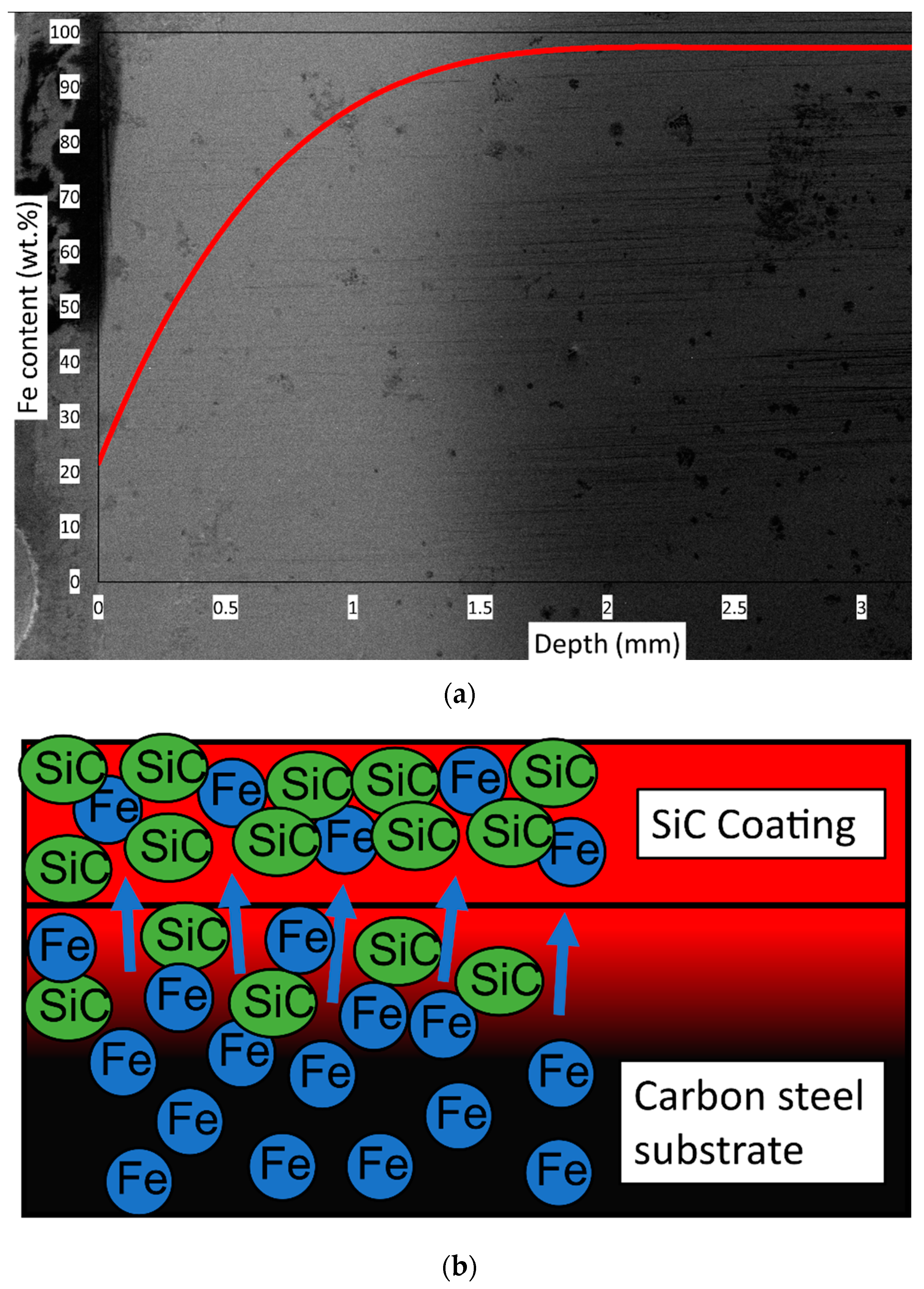
Diffusion transports elements from high-concentration regions to low-concentration regions. As such, this analysis indicates that diffusion of Fe dominated during flash heating, resulting in a large quantity of Fe transferring from the substrate (high Fe concentration) to the coating (low Fe concentration). This process is shown in Figure 12a,b. Figure 12a shows an estimate of the distribution of Fe in terms of weight percent based on the known Fe content in the substrate of 97.265 wt.% and the measured Fe content at the surface from EDS of 21.73 wt.%. In Figure 12b, the red indicates increased temperature, while the arrows indicate the path of diffusion for Fe. Fe is the primary element that diffuses from the substrate due to it accounting for 97.265% of the substrate by weight. This diffusion of Fe may also cause some SiC particles to migrate into the substrate. Although the heat input is localized during flash heating, the energy transferred by heat is still large and rapidly increases the temperature of the substrate for the SiC coating. An increased diffusion coefficient such as is experienced by the substrate the SiC coating is applied to increase the number of Fe atoms diffusing into the SiC coating per unit time. While the time during which this diffusion occurs is short due to the localized heat input, the temperature increase is great enough to cause substantial diffusion, which is unique to this flash heating procedure. As a result, the coating’s composition is Fe-SiC instead of SiC.
4. Conclusions
This research demonstrated the viability of flash heating as a means to fabricate Ni-SiC coatings with high SiC content. All coatings outperformed the carbon steel substrate during hardness tests. The Ni-SiC coating with 30 wt.% SiC improved the surface hardness by 61% compared to the carbon steel substrate, while the coating with 50 wt.% SiC improved the same parameter by 121%, with hardness values similar to superhard minerals such as topaz. Additionally, the hardness variation with depth showed that the coatings greatly improved surface tribological characteristics while minimally affecting the substrate. Tribotests performed on the coatings and substrate also showed that the wear resistance levels of the coatings were greater than that of the substrate, with improvements of 1.83 and 4.71 for the Ni-SiC coatings with 30 and 50 wt.% SiC compared to the substrate, respectively. The pure SiC coating also improved both the hardness and wear over that of the substrate, but to a much more limited degree. This was due to elemental diffusion occurring during the flash heating process as a result of the increased required heat input for the SiC coating. Even though the time in which diffusion occurred was short, the temperature was high, which caused large amounts of Fe to diffuse due to the uniqueness of the flash heating process. This can be prevented by cooling the substrate during flash heating and with the fabrication of thinner coatings than were fabricated in this research.
Author Contributions
Conceptualization, P.R. and H.L.; experimentation: P.R. Topography: A.R. Data analysis, P.R and H.L. Manuscript writing and review: P.R. and H.L. project administration, H.L. All authors have read and agreed to the published version of the manuscript.
Funding
P.R. was funded by the National Science Foundation (NSF) Graduate Research Fellowship.
Institutional Review Board Statement
Not applicable.
Informed Consent Statement
Not applicable.
Data Availability Statement
The data presented in this study are available on request from the corresponding author. The data are not publicly available due to the associated project not being completed at this time.
Conflicts of Interest
The authors declare no conflict of interest.
References
- Garcia, I.; Fransaer, J.; Celis, J.-P. Electrodeposition and sliding wear resistance of nickel composite coatings containing micron and submicron SiC particles. Surf. Coat. Technol. 2001, 148, 171–178. [Google Scholar] [CrossRef]
- Hou, K.; Ger, M.; Wang, L.; Ke, S. The wear behaviour of electro-codeposited Ni–SiC composites. Wear 2002, 253, 994–1003. [Google Scholar] [CrossRef]
- Fini, M.H.; Amadeh, A. Improvement of wear and corrosion resistance of AZ91 magnesium alloy by applying Ni–SiC nanocomposite coating via pulse electrodeposition. Trans. Nonferrous Met. Soc. China 2013, 23, 2914–2922. [Google Scholar] [CrossRef]
- Donnet, C.; Grill, A. Friction control of diamond-like carbon coatings. Surf. Coat. Technol. 1997, 94, 456–462. [Google Scholar] [CrossRef]
- Zhao, J.; Xia, L.; Sehgal, A.; Lu, D.; McCreery, R.; Frankel, G. Effects of chromate and chromate conversion coatings on corrosion of aluminum alloy 2024-T3. Surf. Coat. Technol. 2001, 140, 51–57. [Google Scholar] [CrossRef] [Green Version]
- Fischer-Cripps, A.; Karvánková, P.; Veprek, S. On the measurement of hardness of super-hard coatings. Surf. Coat. Technol. 2006, 200, 5645–5654. [Google Scholar] [CrossRef]
- Wang, H.; Wang, H.; Wang, X. Ni60-SiC coating prepared by plasma spraying, plasma re-melting and plasma spray welding on surface of hot forging die. Mater. Sci. Ed. 2011, 26, 715–718. [Google Scholar] [CrossRef]
- Fu, Y.; Loh, N.L.; Batchelor, A.W.; Liu, D.; Zhu, X.; He, J.; Xu, K. Improvement in fretting wear and fatigue resistance of Ti–6Al–4V by application of several surface treatments and coatings. Surf. Coat. Technol. 1998, 106, 193–197. [Google Scholar] [CrossRef]
- Schwarzacher, W. Electrodeposition: A technology for the future. Electrochem. Soc. Interface 2006, 15, 32–33. [Google Scholar] [CrossRef]
- Besra, L.; Liu, M. A review on fundamentals and applications of electrophoretic deposition (EPD). Prog. Mater. Sci. 2007, 52, 1–61. [Google Scholar] [CrossRef]
- Wang, M. Composite coatings for implants and tissue engineering scaffolds. In Biomedical Composites; Elsevier: Amsterdam, The Netherlands, 2010; Volume 3, pp. 127–177. [Google Scholar]
- Vaezi, M.; Sadrnezhaad, S.; Nikzad, L. Electrodeposition of Ni–SiC nano-composite coatings and evaluation of wear and corrosion resistance and electroplating characteristics. Colloids Surf. A Physicochem. Eng. Asp. 2008, 315, 176–182. [Google Scholar] [CrossRef]
- Jha, S.; Chen, Y.; Renner, P.; Likhari, R.; Stewart, W.; Gharib, M.; Liang, H. Design of Anti-frictional Ceramic-Based Composite Coatings. J. Mater. Eng. Perform. 2021, 11, 1–18. [Google Scholar] [CrossRef]
- Ma, L.; Chen, Y.; Renner, P.; Parkinson, D.; Fang, A.; Liang, H. Synthesis and Morphological Characterization of Electroless-Deposited Ni-P Coatings on Diamond Abrasives. Lubricants 2021, 9, 20. [Google Scholar] [CrossRef]
- He, X.; Xiao, H.; Ozaydin, M.F.; Balzuweit, K.; Liang, H. Low-temperature boriding of high-carbon steel. Surf. Coat. Technol. 2015, 263, 21–26. [Google Scholar] [CrossRef]
- He, X.; Chiu, C.; Esmacher, M.J.; Liang, H. Nanostructured photocatalytic coatings for corrosion protection and surface repair. Surf. Coat. Technol. 2013, 237, 320–327. [Google Scholar] [CrossRef]
- Cardinal, M.F.; Castro, P.; Baxi, J.; Liang, H.; Williams, F.J. Characterization and frictional behavior of nanostructured Ni–W–MoS2 composite coatings. Surf. Coat. Technol. 2009, 204, 85–90. [Google Scholar] [CrossRef]
- Xu, G.H.; Lee, J.H.; Liang, H.; Georing, D. Tribological properties of solid-lubricating coatings on cylinder bore at low temperature. Wear 2004, 257, 59–65. [Google Scholar] [CrossRef]
- Özkan, S.; Hapçı, G.; Orhan, G.; Kazmanlı, K. Electrodeposited Ni/SiC nanocomposite coatings and evaluation of wear and corrosion properties. Surf. Coat. Technol. 2013, 232, 734–741. [Google Scholar] [CrossRef]
- Temam, H.B.; Chala, A.; Rahmane, S. Microhardness and corrosion behavior of Ni–SiC electrodeposited coatings in presence of organic additives. Surf. Coat. Technol. 2011, 205, S161–S164. [Google Scholar] [CrossRef]
- Temam, H.B.; Zeroual, L.; Chala, A.; Rahmane, S.; Nouveau, C. Microhardness and Corrosion Behavior of Ni-SiC Electrodeposited Coatings. Plasma Processes Polym. 2007, 4, S618–S621. [Google Scholar] [CrossRef] [Green Version]
- Zhang, H.; Wang, J.; Chen, S.; Wang, H.; He, Y.; Ma, C. Ni–SiC composite coatings with improved wear and corrosion resistance synthesized via ultrasonic electrodeposition. Ceram. Int. 2021, 47, 9437–9446. [Google Scholar] [CrossRef]
- Hu, F.; Chan, K.C.; Song, S.; Yang, X. Enhancement of corrosion resistance of electrocodeposited Ni-SiC composites by magnetic field. J. Solid State Electrochem. 2007, 11, 745–750. [Google Scholar] [CrossRef]
- Ger, M.-D. Electrochemical deposition of nickel/SiC composites in the presence of surfactants. Mater. Chem. Phys. 2004, 87, 67–74. [Google Scholar] [CrossRef]
- Grosjean, A.; Rezrazi, M.; Takadoum, J.; Bercot, P. Hardness, friction and wear characteristics of nickel-SiC electroless composite deposits. Surf. Coat. Technol. 2001, 137, 92–96. [Google Scholar] [CrossRef]
- Pavlatou, E.; Stroumbouli, M.; Gyftou, P.; Spyrellis, N. Hardening effect induced by incorporation of SiC particles in nickel electrodeposits. J. Appl. Electrochem. 2006, 36, 385–394. [Google Scholar] [CrossRef]
- Balaraju, J.; Narayanan, T.S.; Seshadri, S. Electroless Ni–P composite coatings. J. Appl. Electrochem. 2003, 33, 807–816. [Google Scholar] [CrossRef]
- Zhou, Y.; Zhang, H.; Qian, B. Friction and wear properties of the co-deposited Ni–SiC nanocomposite coating. Appl. Surf. Sci. 2007, 253, 8335–8339. [Google Scholar] [CrossRef]
- Huang, P.-C.; Hou, K.-H.; Hong, J.-J.; Lin, M.-H.; Wang, G.-L. Study of fabrication and wear properties of Ni–SiC composite coatings on A356 aluminum alloy. Wear 2021, 477, 203772. [Google Scholar] [CrossRef]
- Jiang, W.; Shen, L.; Qiu, M.; Xu, M.; Tian, Z. Microhardness, wear, and corrosion resistance of Ni–SiC composite coating with magnetic-field-assisted jet electrodeposition. Mater. Res. Express 2018, 5, 096407. [Google Scholar] [CrossRef]
- Li, R.; Chu, Q.; Liang, J. Electrodeposition and characterization of Ni–SiC composite coatings from deep eutectic solvent. RSC Adv. 2015, 5, 44933–44942. [Google Scholar] [CrossRef]
- Liu, W.; Jiang, K.; Li, Q.; Ma, C.; Xia, F. Jet Pulse Electrodeposited Ni-SiC Thin Coatings by Using Experimental System Designed for Potential Industrial Application. Int. J. Electrochem. Sci. 2021, 16, 21044. [Google Scholar] [CrossRef]
- Bratu, F.; Benea, L.; Celis, J.-P. Tribocorrosion behaviour of Ni–SiC composite coatings under lubricated conditions. Surf. Coat. Technol. 2007, 201, 6940–6946. [Google Scholar] [CrossRef]
- Singh, S.K.; Samanta, S.; Das, A.K.; Sahoo, R.R. Electrodeposited SiC-graphene oxide composite in nickel matrix for improved tribological applications. Surf. Topogr. Metrol. Prop. 2019, 7, 035004. [Google Scholar] [CrossRef]
- Renner, P.; Chen, Y.; Huang, Z.; Raut, A.; Liang, H. Tribocorrosion Influenced Pitting of a Duplex Stainless Steel. Lubricants 2021, 9, 52. [Google Scholar] [CrossRef]
- Wang, Y.-Q.; Jie, T.; Ling, W.; He, P.-T.; Tao, W. HA coating on titanium with nanotubular anodized TiO2 intermediate layer via electrochemical deposition. Trans. Nonferrous Met. Soc. China 2008, 18, 631–635. [Google Scholar] [CrossRef]
- Wang, J.; Chao, Y.; Wan, Q.; Zhu, Z.; Yu, H. Fluoridated hydroxyapatite coatings on titanium obtained by electrochemical deposition. Acta Biomater. 2009, 5, 1798–1807. [Google Scholar] [CrossRef]
- Xiao, X.F.; Liu, R.F. Effect of suspension stability on electrophoretic deposition of hydroxyapatite coatings. Mater. Lett. 2006, 60, 2627–2632. [Google Scholar] [CrossRef]
- Li, B.; Zhang, W.; Zhang, W.; Huan, Y. Preparation of Ni-W/SiC nanocomposite coatings by electrochemical deposition. J. Alloy. Compd. 2017, 702, 38–50. [Google Scholar] [CrossRef]
- Niu, Z.-X.; Cao, F.; Wei, W.; Zhang, Z.; Zhang, J.; Cao, C.-N. Electrodeposition of Ni-SiC nanocomposite film. Trans. Nonferrous Met. Soc. China 2007, 17, 9–15. [Google Scholar] [CrossRef]
- Gyawali, G.; Hamal, K.; Joshi, B.; Rajbhandari, A.; Lee, S.W. Microstructural and electrochemical analysis of Ni–SiC composite coatings prepared in presence of additives. Mater. Lett. 2014, 126, 228–231. [Google Scholar] [CrossRef]
- Wang, H.; Yao, S.; Matsumura, S. Electrochemical preparation and characterization of Ni/SiC gradient deposit. J. Mater. Processing Technol. 2004, 145, 299–302. [Google Scholar] [CrossRef]
- Baron, A.; Guerrero, J.; González, J.; Gómez, A.; Jurado, A.; Sthepa, H.S. Effect of Ni content on the microstructure, thermal properties, and morphology of Ni-SiC composites produced by mechanical alloying. Ceram. Int. 2017, 43, 2592–2597. [Google Scholar] [CrossRef]
- Abubakar, A.A.; Arif, A.F.M.; Al-Athel, K.S.; Akhtar, S.S.; Mostaghimi, J. Modeling residual stress development in thermal spray coatings: Current status and way forward. J. Therm. Spray Technol. 2017, 26, 1115–1145. [Google Scholar] [CrossRef]
- Abbas, R.A.; Ajeel, S.A.; Bash, M.A.A.; Kadhim, M.J. Effect of plasma spray distance on the features and hardness reliability of YSZ thermal barrier coating. Mater. Today Proc. 2021, 42, 2553–2560. [Google Scholar] [CrossRef]
- Marple, B.; Voyer, J.; Bisson, J.-F.; Moreau, C. Thermal spraying of nanostructured cermet coatings. J. Mater. Processing Technol. 2001, 117, 418–423. [Google Scholar] [CrossRef]
- La Barbera-Sosa, J.; Santana, Y.; Moreno, E.; Cuadrado, N.; Caro, J.; Renault, P.; Le Bourhis, E.; Staia, M.; Puchi-Cabrera, E. Effect of spraying distance on the microstructure and mechanical properties of a Colmonoy 88 alloy deposited by HVOF thermal spraying. Surf. Coat. Technol. 2010, 205, 1799–1806. [Google Scholar] [CrossRef]
- Chang, C. Thermal Spray: International Advances in Coatings Technology; Materials Park—ASM International: Novelty, OH, USA, 1992; p. 79398. [Google Scholar]
- Pierlot, C.; Pawlowski, L.; Bigan, M.; Chagnon, P. Design of experiments in thermal spraying: A review. Surf. Coat. Technol. 2008, 202, 4483–4490. [Google Scholar] [CrossRef]
- Mubarok, F.; Espallargas, N. Tribological behaviour of thermally sprayed silicon carbide coatings. Tribol. Int. 2015, 85, 56–65. [Google Scholar] [CrossRef]
- Draper, C.; Poate, J. Laser surface alloying. Int. Met. Rev. 1985, 30, 85–108. [Google Scholar] [CrossRef]
- Selvan, J.S.; Subramanian, K.; Nath, A.K. Laser surface alloying of (pre-placed) SiC and Ni-SiC coating on commercially pure titanium. Mater. Manuf. Processes 1999, 14, 285–296. [Google Scholar] [CrossRef]
- Yang, R.; Liu, Z.; Yang, G.; Wang, Y. Study of In-situ Synthesis TiCp/Ti Composite Coating on Alloy Ti6Al4 V by TIG Cladding. Procedia Eng. 2012, 36, 349–354. [Google Scholar] [CrossRef] [Green Version]
- Qi, X.; Song, G. Interfacial structure of the joints between magnesium alloy and mild steel with nickel as interlayer by hybrid laser-TIG welding. Mater. Des. 2010, 31, 605–609. [Google Scholar] [CrossRef]
- Zhang, G.; Tian, C.; Liu, L.; Xu, R. Interfacial Structure of the Joints between Magnesium Alloy andmild Steel with Nickel as Interlayer. In Proceedings of the International Conference on Logistics Engineering, Management and Computer Science (LEMCS 2014), Shenyang, China, 24–26 May 2014; Atlantis Press: Amsterdam, The Netherlands, 2014; pp. 335–338. [Google Scholar]
- Ghadami, F.; Sohi, M.H.; Ghadami, S. Effect of TIG surface melting on structure and wear properties of air plasma-sprayed WC–Co coatings, Surface and Coatings Technology. In Proceedings of the International Conference on Logistics Engineering, Management and Computer Science (LEMCS 2014), Shenyang, China, 24–26 May 2014; Atlantis Press: Amsterdam, The Netherlands, 2015; pp. 108–113. [Google Scholar]
- Dong, T.; Zheng, X.; Li, G.; Wang, H.; Liu, M.; Zhou, X.; Li, Y. Effect of Tungsten Inert Gas Remelting on Microstructure, Interface and Wear Resistance of Fe-Based Coating. J. Eng. Mater. Technol. 2018, 140, 041007. [Google Scholar] [CrossRef]
- Li, J.; Lin, O.; Cheng, C.; Wang, W.; Xu, C.; Ren, L. Fabrication of a Ni/SiC composite coating on steel surface with excellent corrosion inhibition performance. J. Mater. Processing Technol. 2021, 290, 116987. [Google Scholar] [CrossRef]
- Babu, A.; Arora, H.; Singh, R.; Grewal, H. Slurry Erosion Resistance of Microwave Derived Ni-SiC Composite Claddings. Silicon 2021, 14, 1–13. [Google Scholar] [CrossRef]
- Babu, A.; Arora, H.; Singh, H.; Grewal, H. Microwave synthesized composite claddings with enhanced cavitation erosion resistance. Wear 2019, 422, 242–251. [Google Scholar] [CrossRef]
- Ozimina, D.; Madej, M.; Kałdoński, T. The wear resistance of HVOF sprayed composite coatings. Tribol. Lett. 2011, 41, 103–111. [Google Scholar] [CrossRef]
- Xu, J.; Zhang, C.; Sun, G.; Xiao, J.; Zhang, L.; Zhang, G. Role of SiC nanoparticles on tribological properties of atmospheric plasma sprayed 5 wt% SiC–Ni60 coatings. Tribol. Int. 2020, 146, 106220. [Google Scholar] [CrossRef]
- Huang, R.-S.; Liu, L.-M.; Song, G. Infrared temperature measurement and interference analysis of magnesium alloys in hybrid laser-TIG welding process. Mater. Sci. Eng. A 2007, 447, 239–243. [Google Scholar] [CrossRef]
- Choo, R.T.C.; Szekely, J.; Westhoff, R.C. On the calculation of the free surface temperature of gas-tungsten-arc weld pools from first principles: Part I. Modeling the welding arc. Metall. Mater. Trans. B 1992, 23, 357–369. [Google Scholar] [CrossRef]
- Choo, R.T.C.; Szekely, J.; David, S.A. On the calculation of the free surface temperature of gas-tungsten-arc weld pools from first principles: Part II. Modeling the weld pool and comparison with experiments. Metall. Mater. Trans. B 1992, 23, 371–384. [Google Scholar] [CrossRef]
- Xu, J.; Wang, K.; Zhang, R.; Guo, Q.; Wang, P.; Chen, R.; Zeng, D.; Li, F.; Guo, J.; Li, L. An investigation into the microstructure and tribological properties of rail materials with plasma selective quenching. Tribol. Int. 2020, 146, 106032. [Google Scholar] [CrossRef]
- Wang, Z.; Wang, C.-W.; Wang, M.; Zhao, Q.-Z. Manipulation of tribological properties of stainless steel by picosecond laser texturing and quenching. Tribol. Int. 2016, 99, 14–22. [Google Scholar] [CrossRef]
- Xia, Y.-Q.; Liu, W.-M.; Xue, Q.-J. Comparative study of the tribological properties of various modified mild steels under boundary lubrication condition. Tribol. Int. 2005, 38, 508–514. [Google Scholar] [CrossRef]
- Liang, H.; Kaufman, F.; Sevilla, R.; Anjur, S. Wear phenomena in chemical mechanical polishing. Wear 1997, 211, 271–279. [Google Scholar] [CrossRef]
- Liang, H.; Xu, G.H. Lubricating behavior in chemical–mechanical polishing of copper. Scr. Mater. 2002, 46, 343–347. [Google Scholar] [CrossRef]
- Chekina, O.G.; Keer, L.M.; Liang, H. Wear-Contact Problems and Modeling of Chemical Mechanical Polishing. J. Electrochem. Soc. 1998, 145, 2100. [Google Scholar] [CrossRef]
- Estragnat, E.; Tang, G.; Liang, H.; Jahanmir, S.; Pei, P.; Martin, J.M. Experimental investigation on mechanisms of silicon chemical mechanical polishing. J. Electron. Mater. 2004, 33, 334–339. [Google Scholar] [CrossRef]
- Knoop, F.; Peters, C.; Emerson, W. A sensitive pyramidal-diamond tool for indentation measurements. J. Res. Natl. Bur. Stand. 1939, 23, 39. [Google Scholar] [CrossRef]
- Ritter, J.E.; Mahoney, F.M.; Jakus, K. A comparison of Vickers and Knoop indentations in soda-lime glass. In Fracture Mechanics of Ceramics; Springer: Berlin/Heidelberg, Germany, 1986; pp. 213–223. [Google Scholar]
- Shahdad, S.A.; McCabe, J.F.; Bull, S.; Rusby, S.; Wassell, R.W. Hardness measured with traditional Vickers and Martens hardness methods. Dent. Mater. 2007, 23, 1079–1085. [Google Scholar] [CrossRef]
- Ferro, D.; Barinov, S.; Rau, J.; Latini, A.; Scandurra, R.; Brunetti, B. Vickers and Knoop hardness of electron beam deposited ZrC and HfC thin films on titanium. Surf. Coat. Technol. 2006, 200, 4701–4707. [Google Scholar] [CrossRef]
- Standard, A. Standard test method for microindentation hardness of materials. ASTM Int. 2017, E384. [Google Scholar]
- Delaunay, B. Sur la sphere vide. Izv. Akad. Nauk. SSSR Otd. Mat. I Estestv. Nauk. 1934, 7, 1–2. [Google Scholar]
- Lee, D.T.; Schachter, B.J. Two algorithms for constructing a Delaunay triangulation. Int. J. Comput. Inf. Sci. 1980, 9, 219–242. [Google Scholar] [CrossRef]
- Crank, J. The Mathematics of Diffusion; Oxford University Press: Oxford, UK, 1979. [Google Scholar]
- Mehrer, H. Diffusion in Solids: Fundamentals, Methods, Materials, Diffusion-Controlled Processes; Springer Science and Business Media: Berlin/Heidelberg, Germany, 2007. [Google Scholar]
- Shewmon, P. Diffusion in Solids; Springer: Berlin/Heidelberg, Germany, 2016. [Google Scholar]
- Carslaw, H.S.; Jaeger, J.C. Conduction of Heat in Solids; Oxford University Press: Oxford, UK, 1959. [Google Scholar]
- Gyftou, P.; Stroumbouli, M.; Pavlatou, E.; Spyrellis, N. Electrodeposition of Ni/SiC composites by pulse electrolysis. Trans. IMF 2002, 80, 88–91. [Google Scholar] [CrossRef]
- Winchell, H. The Knoop microhardness tester as a mineralogical tool. Am. Mineral. J. Earth Planet. Mater. 1945, 30, 583–595. [Google Scholar]
- Zhang, Z.; Li, X.; Almandoz, E.; Fuentes, G.G.; Dong, H. Sliding friction and wear behaviour of Titanium-Zirconium-Molybdenum (TZM) alloy against Al2O3 and Si3N4 balls under several environments and temperatures. Tribol. Int. 2017, 110, 348–357. [Google Scholar] [CrossRef]
- Živić, F.; Babić, M.; Mitrović, S.; Todorović, P. Interpretation of the friction coefficient during reciprocating sliding of Ti6Al4V alloy against Al2O3. Tribol. Ind. 2011, 33, 36–42. [Google Scholar]
- Parchovianský, M.; Balko, J.; Švančárek, P.; Sedláček, J.; Dusza, J.; Lofaj, F.; Galusek, D. Mechanical properties and sliding wear behaviour of Al2O3-SiC nanocomposites with 3–20 vol% SiC. J. Eur. Ceram. Soc. 2017, 37, 4297–4306. [Google Scholar] [CrossRef]
- Archard, J.F.; Hirst, W. The wear of metals under unlubricated conditions. Proc. R. Soc. Lond. Ser. A Math. Phys. Sci. 1956, 236, 397–410. [Google Scholar]
- Renner, P.; Gharib, M.; Liang, H. Tribological Evaluation of a High-Performance Composite Coating. In Proceedings of the ASME 2021 International Mechanical Engineering Conference and Exhibition, Virtual Online, 1–5 November 2021. [Google Scholar]
- Archard, J. Contact and rubbing of flat surfaces. J. Appl. Phys. 1953, 24, 981–988. [Google Scholar] [CrossRef]
- Adachi, K.; Kato, K.; Chen, N. Wear map of ceramics. Wear 1997, 203, 291–301. [Google Scholar] [CrossRef]
- Vaughn, W.L.; Maahs, H.G. Active-to-passive transition in the oxidation of silicon carbide and silicon nitride in air. J. Am. Ceram. Soc. 1990, 73, 1540–1543. [Google Scholar] [CrossRef]
- Park, D.J.; Jung, Y.I.; Kim, H.G.; Park, J.Y.; Koo, Y.H. Oxidation behavior of silicon carbide at 1200 C in both air and water–vapor-rich environments. Corros. Sci. 2014, 88, 416–422. [Google Scholar] [CrossRef]
- Keys, L. The oxidation of silicon carbide. In Symposium on Properties of High Temperature Alloys with Emphasis on Environmental Effects, Las Vegas; The Electrochemical Society: Princeton, NJ, USA, 1976; Volume 1976. [Google Scholar]
- Gulbransen, E.A.; Andrew, K.F.; Brassart, F.A. The oxidation of silicon carbide at 1150 to 1400 °C and at 9 × 10⁻³ to 5 × 10⁻¹ torr oxygen pressure. J. Electrochem. Soc. 1966, 113, 1311. [Google Scholar] [CrossRef]
- Sahoo, P.; Wilkins, C.; Yeager, J. Threshold selection using Renyi’s entropy. Pattern Recognit. 1997, 30, 71–84. [Google Scholar] [CrossRef]
Figure 1.
A schematic of the coating application process.

Figure 2.
(a) Knoop hardness indentations on the Ni-SiC 70-30 surface taken under optical microscopy, (b) Knoop hardness values of the surfaces of the three coatings analyzed in this research, along with the substrate and the reference material of annealed E52100 bearing steel.
Figure 2.
(a) Knoop hardness indentations on the Ni-SiC 70-30 surface taken under optical microscopy, (b) Knoop hardness values of the surfaces of the three coatings analyzed in this research, along with the substrate and the reference material of annealed E52100 bearing steel.
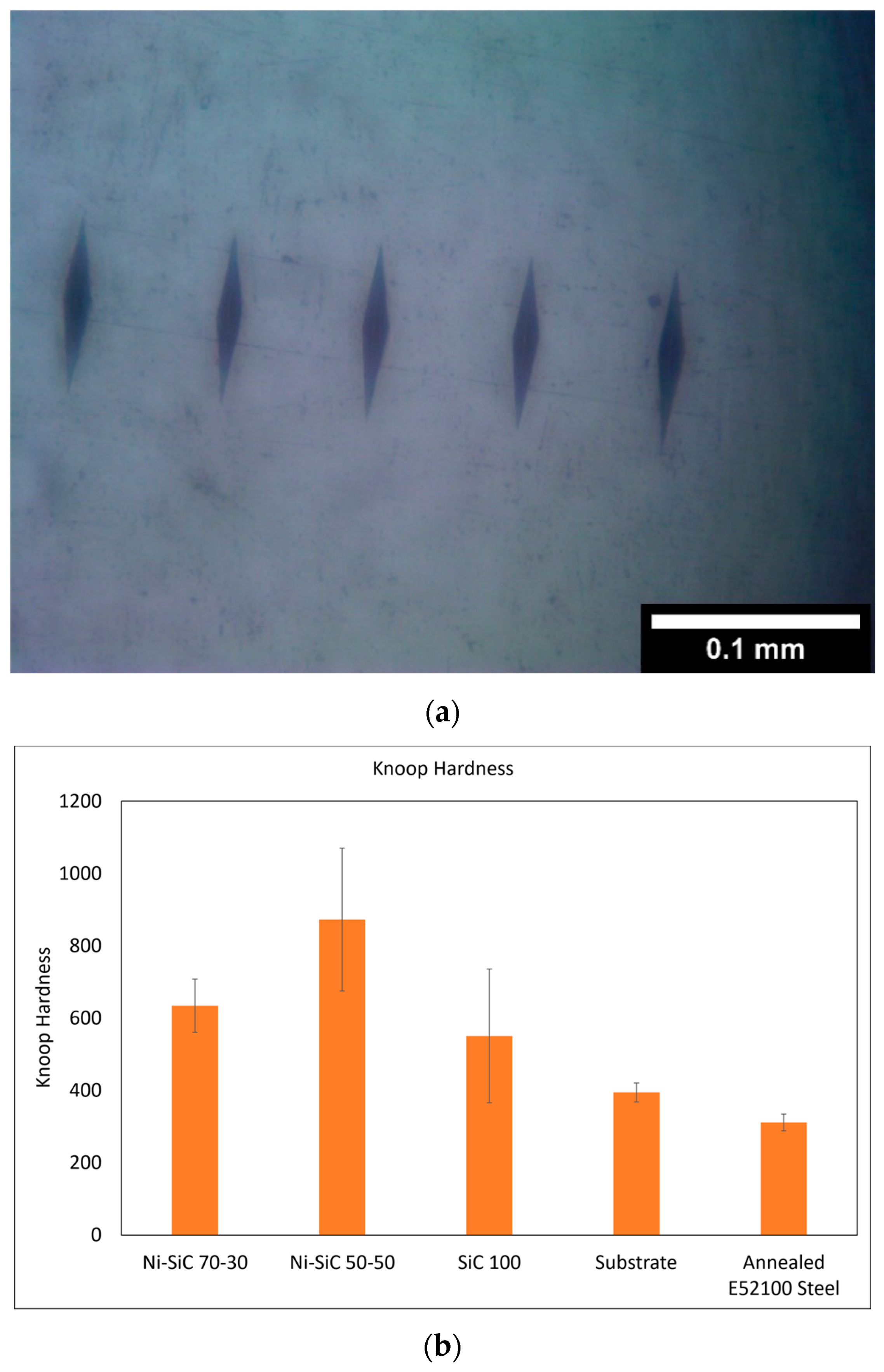
Figure 3.
The average and standard deviation of the cross-section Knoop hardness tests for the (a) Ni-SiC 70-30 coating, (b) Ni-SiC 50-50 coating, and (c) SiC coating.
Figure 3.
The average and standard deviation of the cross-section Knoop hardness tests for the (a) Ni-SiC 70-30 coating, (b) Ni-SiC 50-50 coating, and (c) SiC coating.
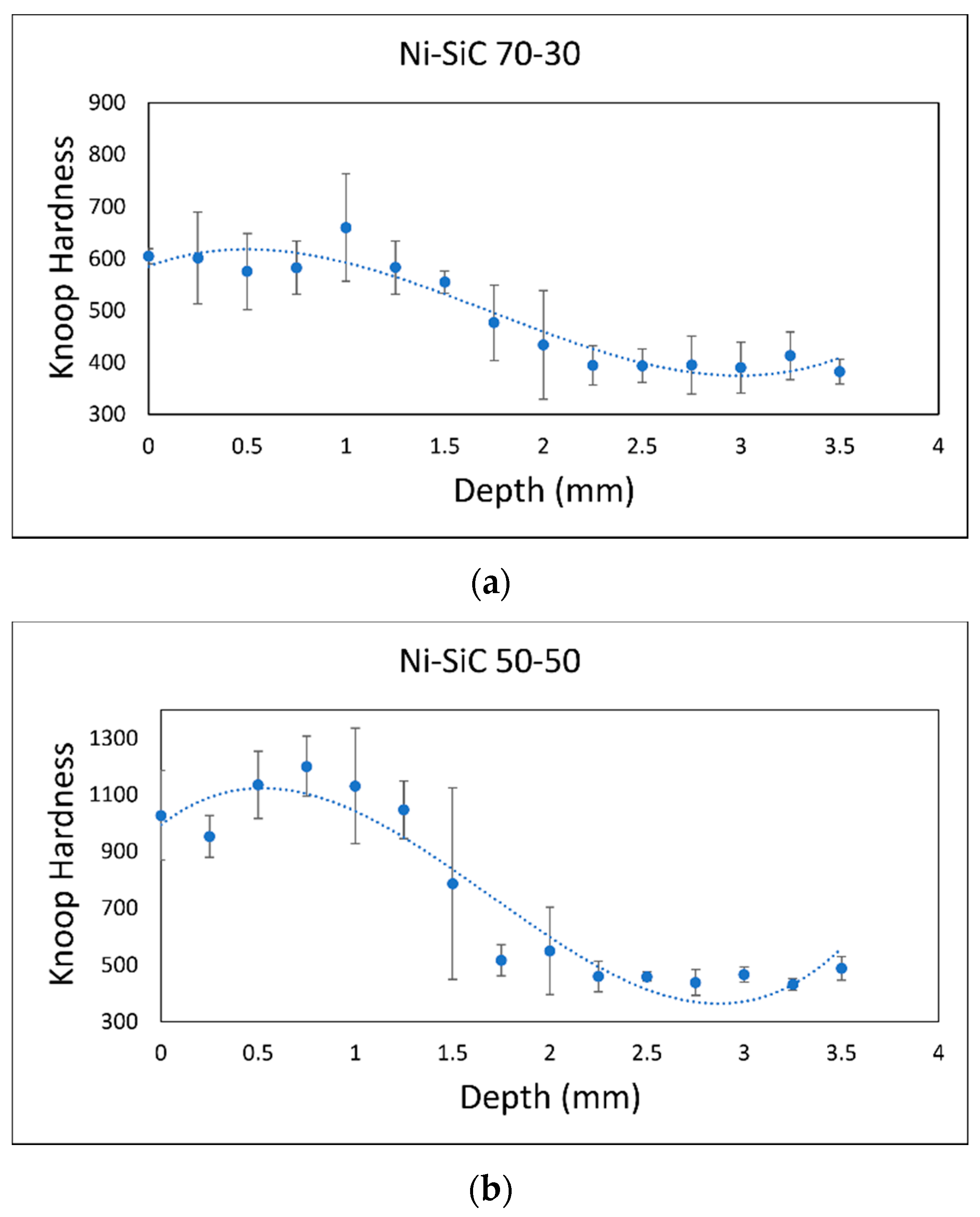
Figure 4.
Cross-sections of (a) the Ni-SiC 70-30 coating, (b) Ni-SiC 50-50 coating, and (c) SiC coating with their hardness profiles overlayed to show hardness evolution into the substrate. The left side shows the coating surface in all images.
Figure 4.
Cross-sections of (a) the Ni-SiC 70-30 coating, (b) Ni-SiC 50-50 coating, and (c) SiC coating with their hardness profiles overlayed to show hardness evolution into the substrate. The left side shows the coating surface in all images.
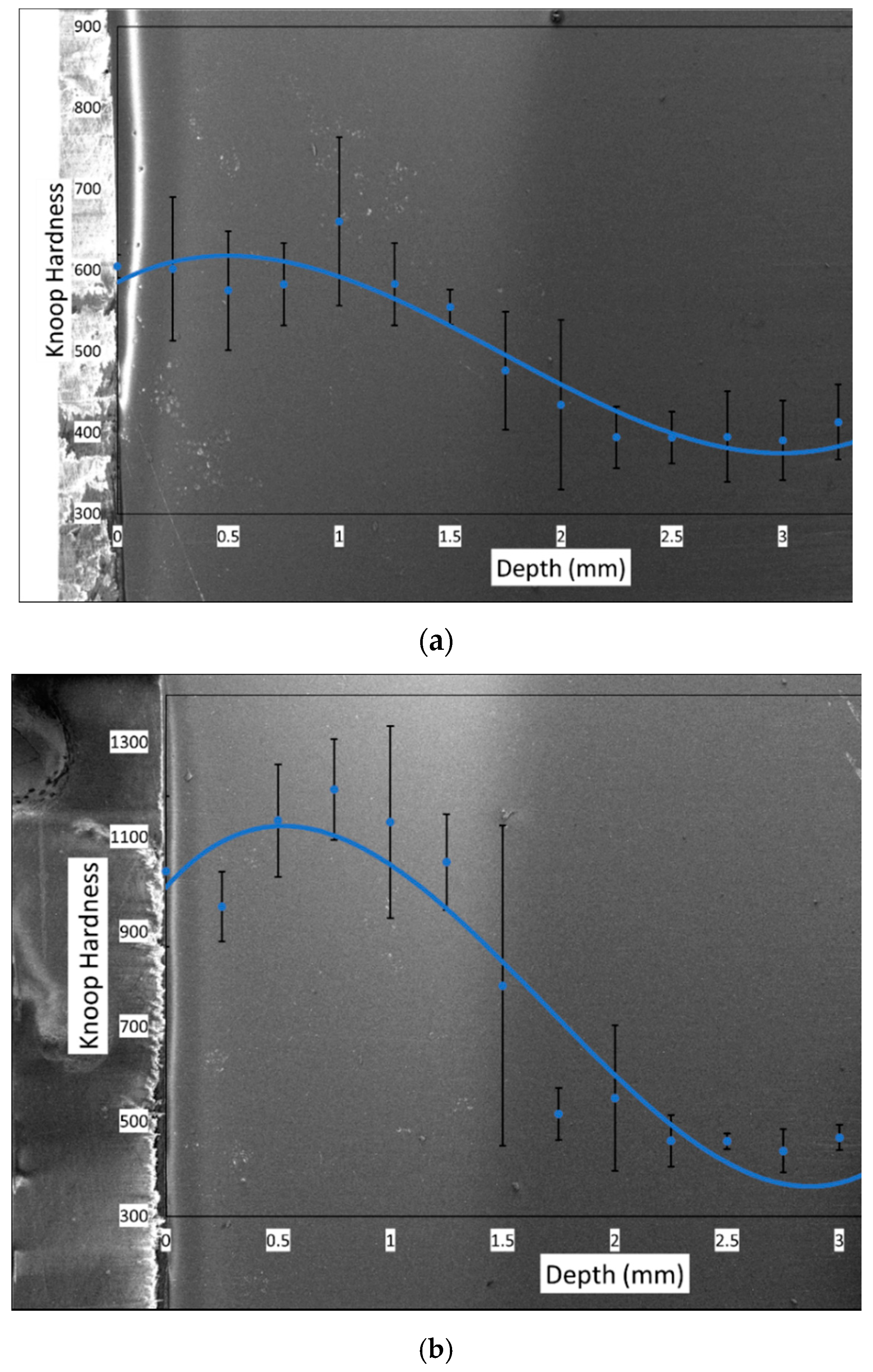
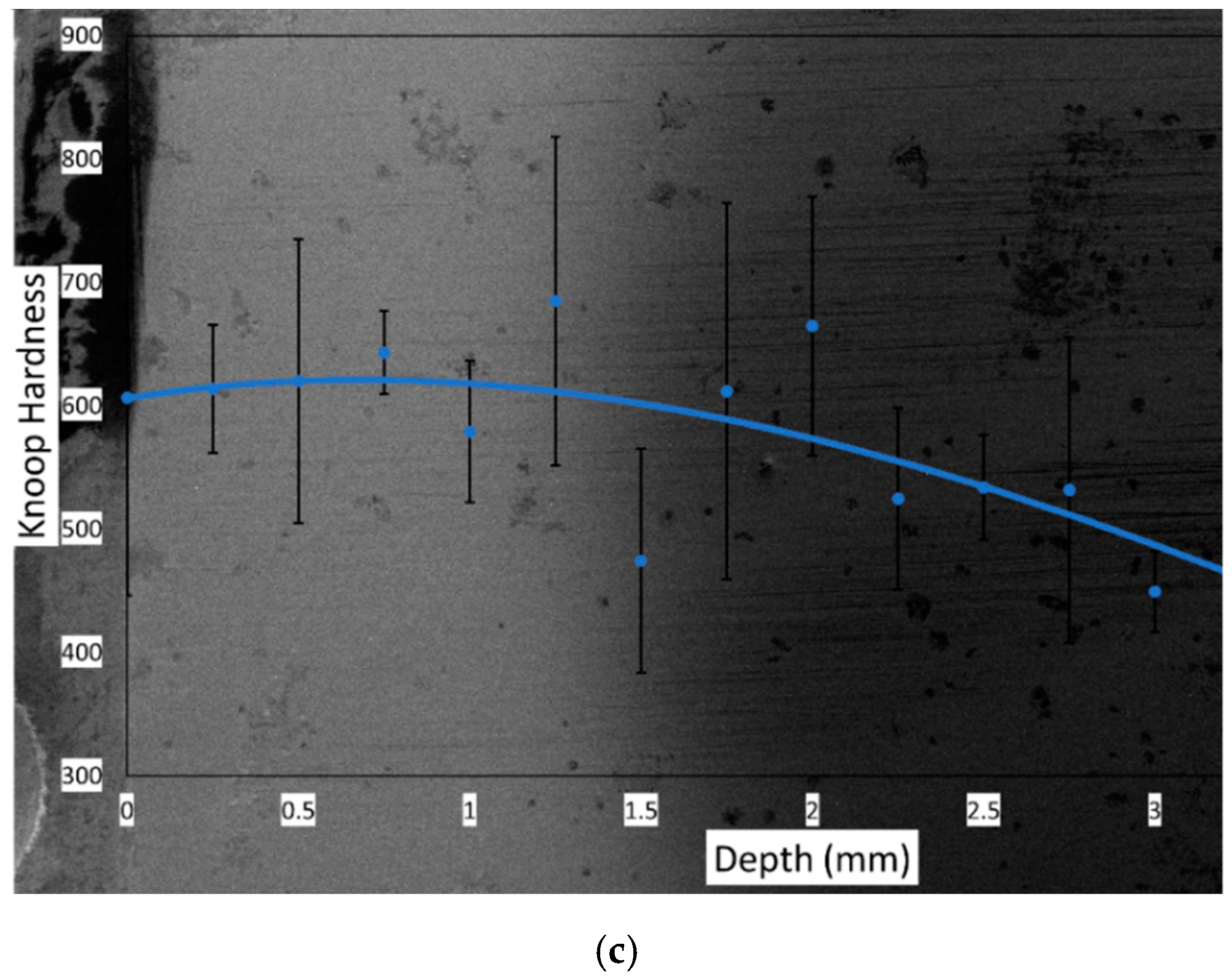
Figure 5.
The surface of the cold-worked E52100 bearing steel ball initially used for tribotesting under SEM. The circle is a flat plane as a result of the wear the ball experienced.
Figure 5.
The surface of the cold-worked E52100 bearing steel ball initially used for tribotesting under SEM. The circle is a flat plane as a result of the wear the ball experienced.
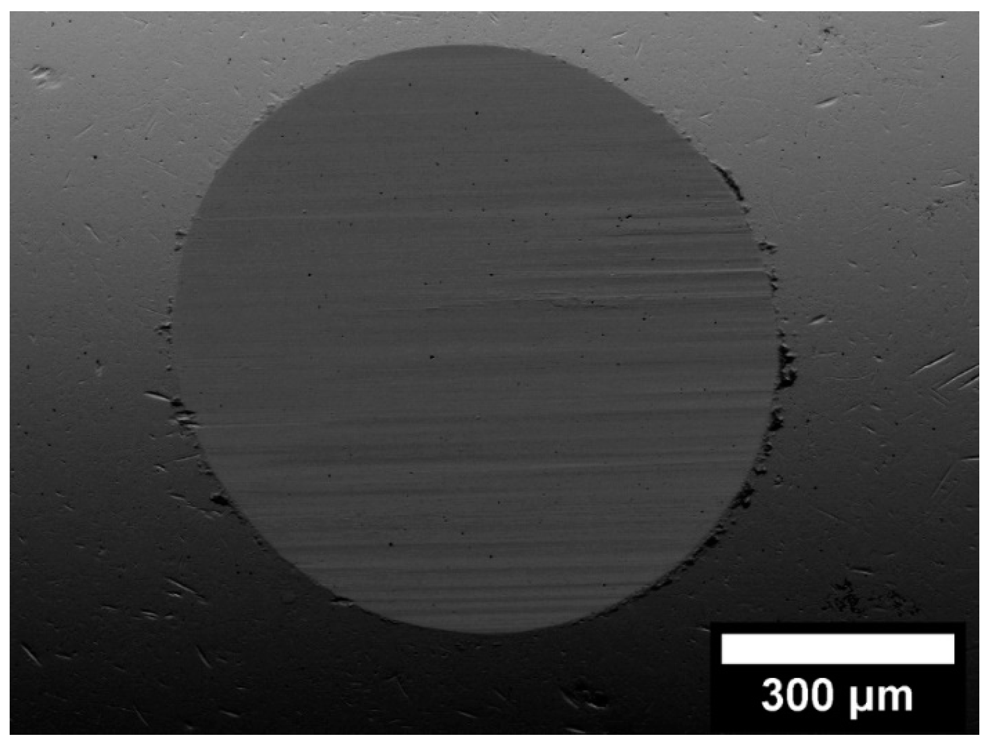
Figure 6.
Coefficient of friction plotted against time during wear tests against an Al2O3 ball counterpart for the substrate and three coatings.
Figure 6.
Coefficient of friction plotted against time during wear tests against an Al2O3 ball counterpart for the substrate and three coatings.
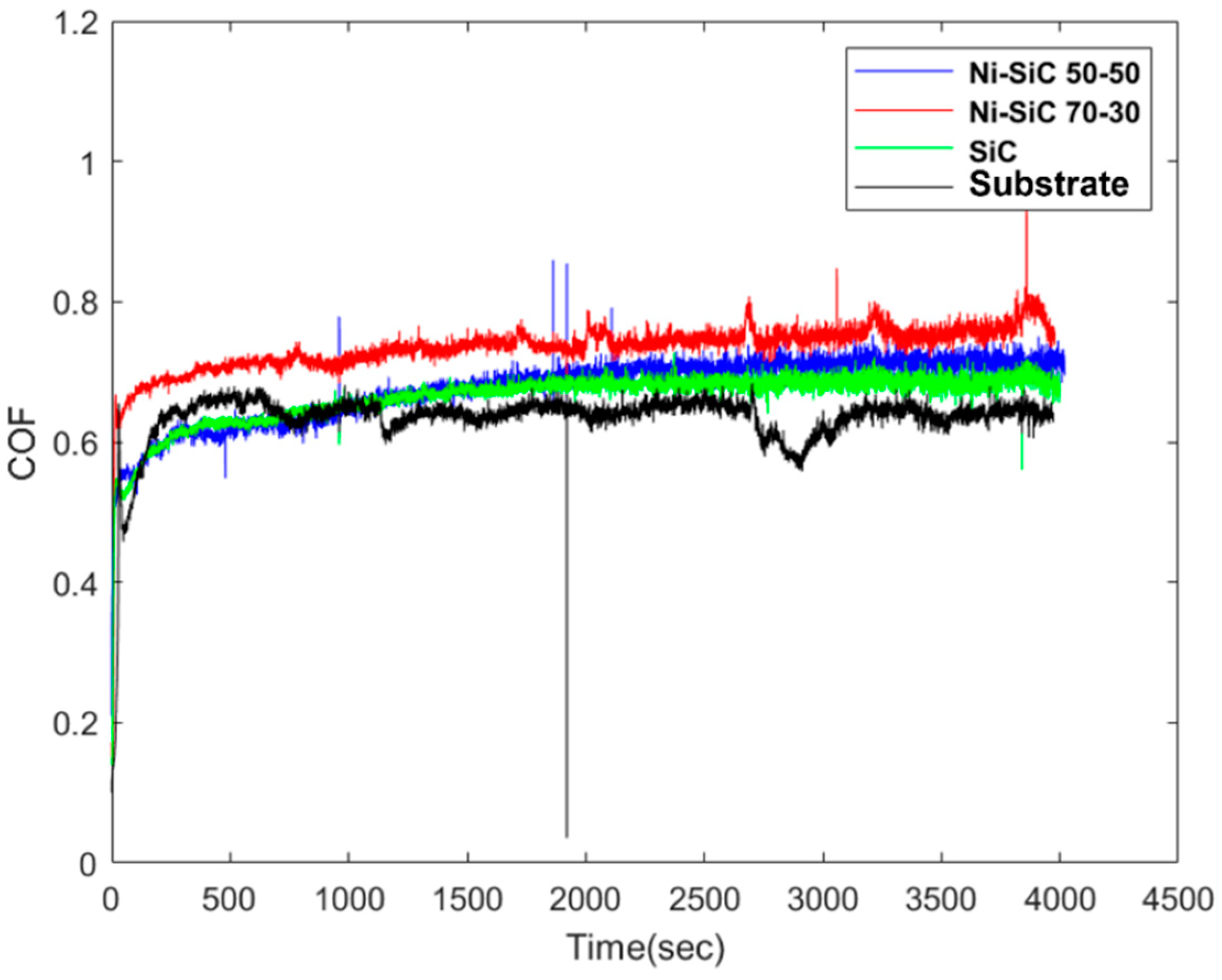
Figure 7.
The substrate’s (a) surface topography after the wear test and (b) cross-section profile at the location of the line shown in (a).
Figure 7.
The substrate’s (a) surface topography after the wear test and (b) cross-section profile at the location of the line shown in (a).
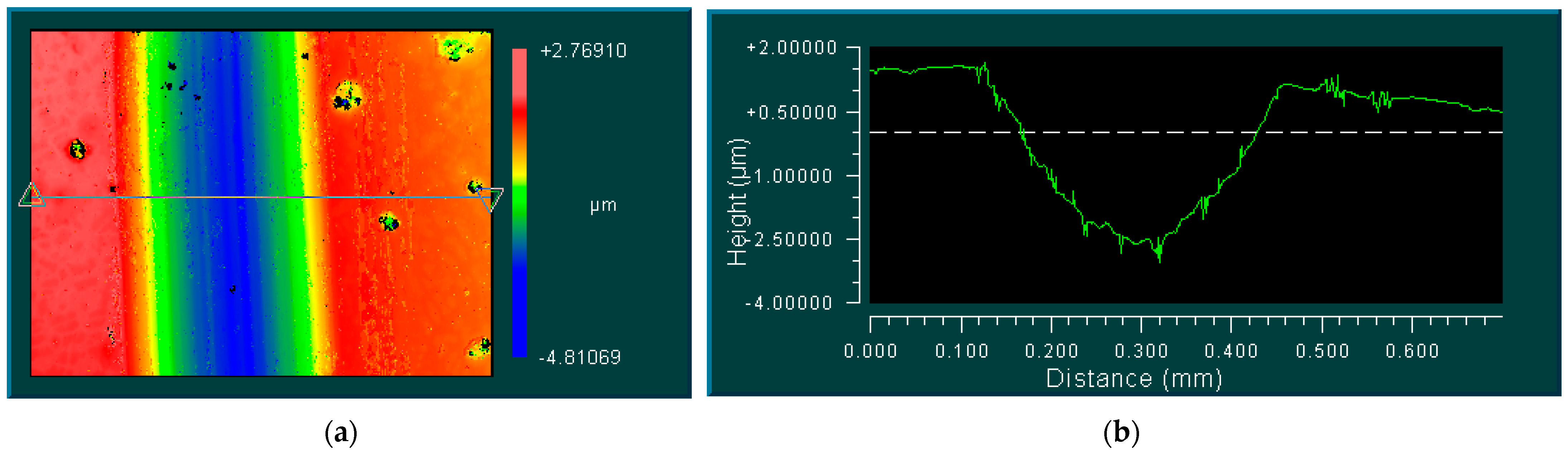
Figure 8.
(a,c,e) The wear scar topography and (b,d,f) cross-section profiles of the Ni-SiC 70-30 coating, Ni-SiC 50-50 coating, and SiC coating, respectively.
Figure 8.
(a,c,e) The wear scar topography and (b,d,f) cross-section profiles of the Ni-SiC 70-30 coating, Ni-SiC 50-50 coating, and SiC coating, respectively.
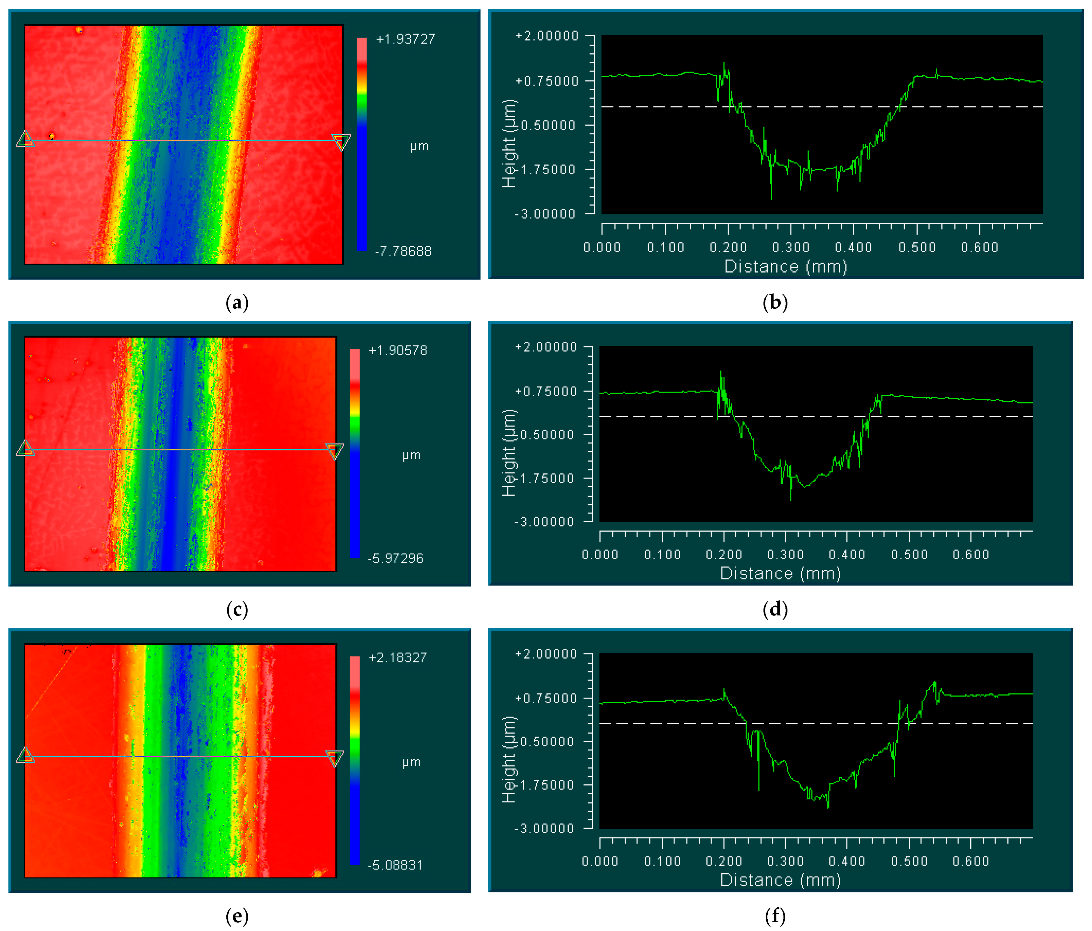
Figure 9.
The base-10 log of the wear volume in µm3 versus the Knoop hardness on the surfaces of the three coatings along with the substrate.
Figure 9.
The base-10 log of the wear volume in µm3 versus the Knoop hardness on the surfaces of the three coatings along with the substrate.

Figure 10.
EDS results for the SiC coatings showing the elemental distributions of (a) C, (b) O, (c) Fe, and (d) Si. These were taken at the top surface of the SiC coating.
Figure 10.
EDS results for the SiC coatings showing the elemental distributions of (a) C, (b) O, (c) Fe, and (d) Si. These were taken at the top surface of the SiC coating.
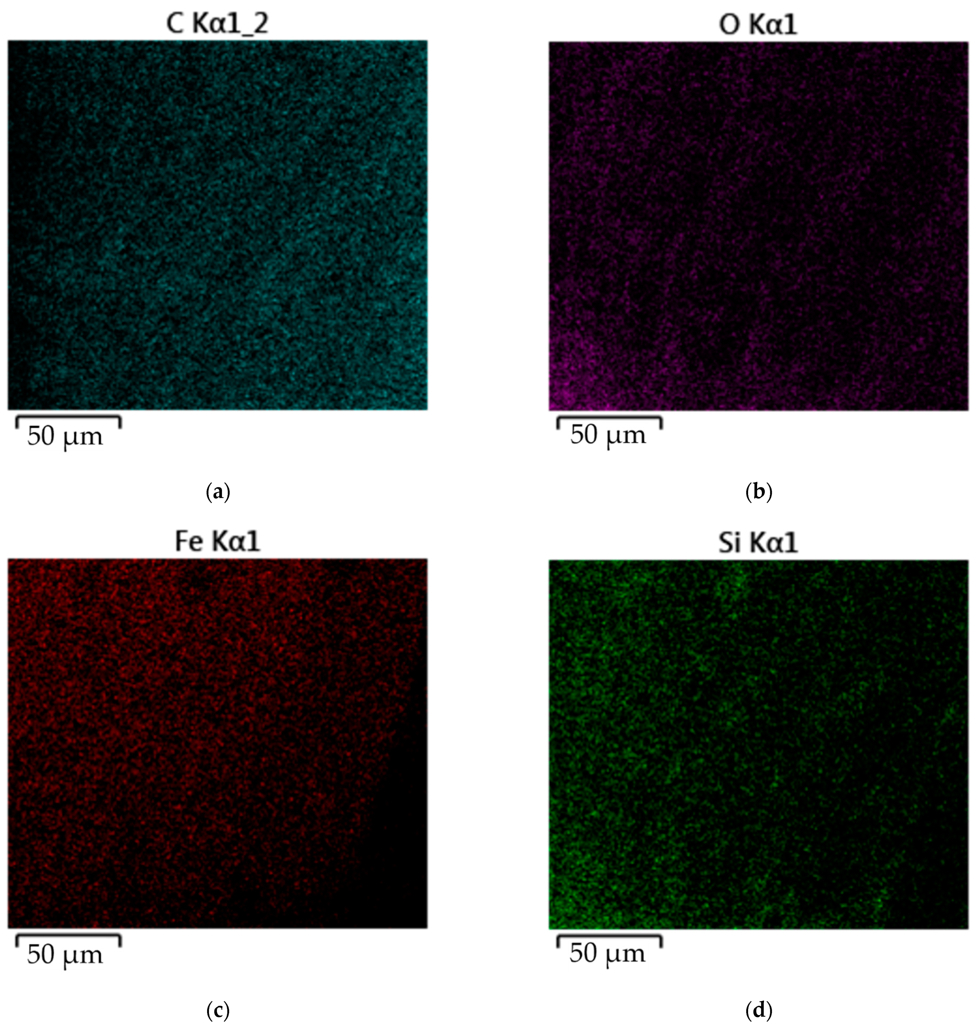
Figure 11.
SEM image of the SiC coating’s top surface.
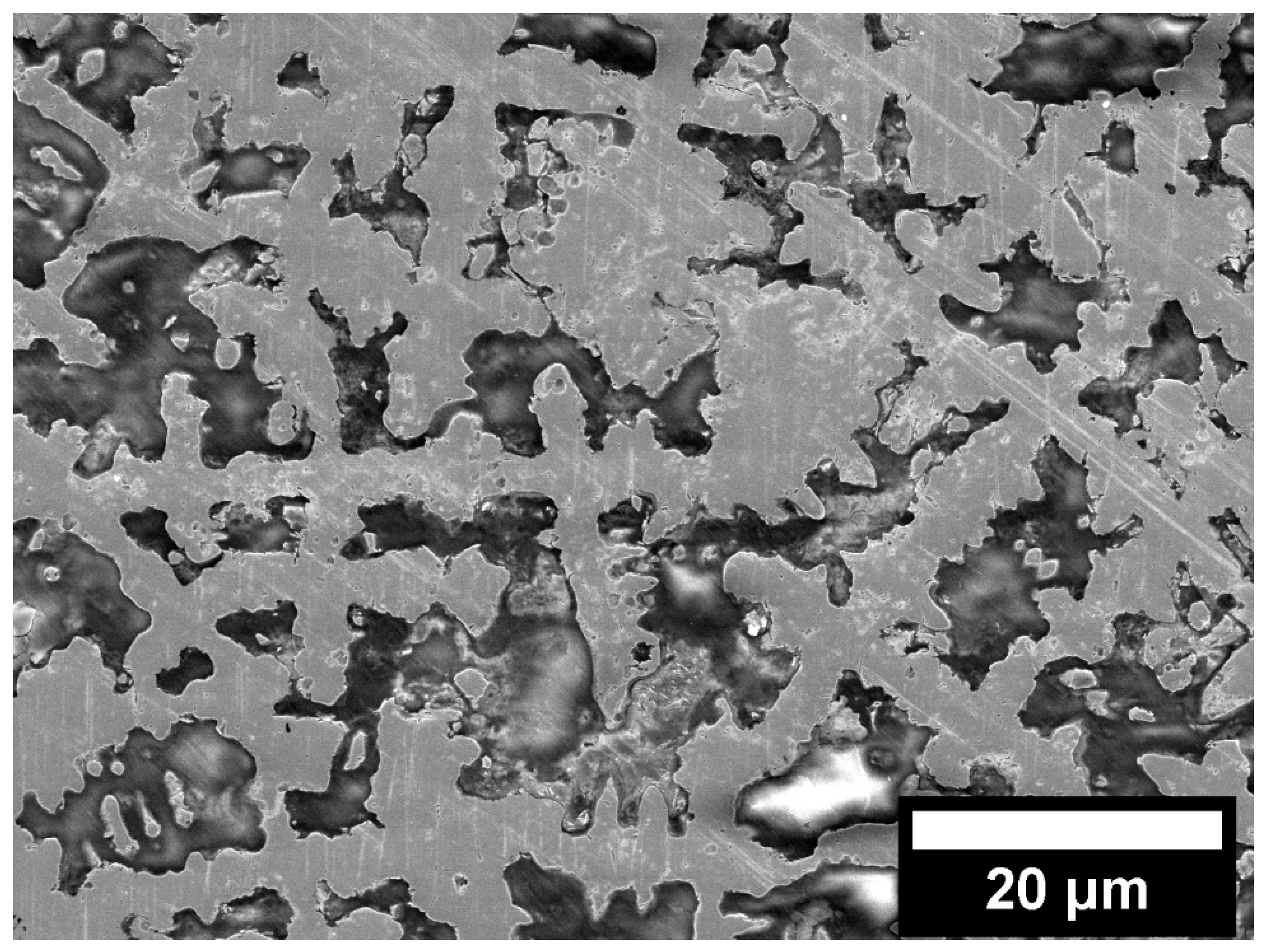
Figure 12.
(a) An estimate of the Fe content distribution for the SiC coating and (b) the primary diffusion processes that occur in the SiC coating during Flash heating.
Figure 12.
(a) An estimate of the Fe content distribution for the SiC coating and (b) the primary diffusion processes that occur in the SiC coating during Flash heating.

Table 1.
Substrate composition in wt.%.
| C | Mn | P | S | Si | Cu | Ni | Cr | Fe |
|---|---|---|---|---|---|---|---|---|
| 0.81 | 0.98 | 0.012 | 0.013 | 0.28 | 0.3 | 0.11 | 0.23 | Balance |
Table 2.
The compositions of the three coatings analyzed in this research.
| Coating | Ni (wt%) | SiC (wt%) |
|---|---|---|
| 1 | 70 | 30 |
| 2 | 50 | 50 |
| 3 | 0 | 100 |
Table 3.
The average roughness and RMS values of the three different coatings along with the substrate after CMP.
Table 3.
The average roughness and RMS values of the three different coatings along with the substrate after CMP.
| Coating | Ra (µm) | RMS (µm) |
|---|---|---|
| 1 (Ni-SiC 70-30) | 0.063 | 0.080 |
| 2 (Ni-SiC 50-50) | 0.060 | 0.083 |
| 3 (SiC) | 0.067 | 0.097 |
| Substrate | 0.056 | 0.073 |
Table 4.
The wear rates for the substrate and coatings.
| Coating | Ni-SiC 70-30 | Ni-SiC 50-50 | SiC | Substrate |
|---|---|---|---|---|
| Wear rate (mm3/N·m) | 2.91 × 10⁻⁶ | 1.13 × 10⁻⁶ | 4.53 × 10⁻⁶ | 5.34 × 10⁻⁶ |
Publisher’s Note: MDPI stays neutral with regard to jurisdictional claims in published maps and institutional affiliations. |
© 2022 by the authors. Licensee MDPI, Basel, Switzerland. This article is an open access article distributed under the terms and conditions of the Creative Commons Attribution (CC BY) license (https://creativecommons.org/licenses/by/4.0/).
Share and Cite
MDPI and ACS Style
Renner, P.; Raut, A.; Liang, H. High-Performance Ni-SiC Coatings Fabricated by Flash Heating. Lubricants 2022, 10, 42. https://doi.org/10.3390/lubricants10030042
AMA Style
Renner P, Raut A, Liang H. High-Performance Ni-SiC Coatings Fabricated by Flash Heating. Lubricants. 2022; 10(3):42. https://doi.org/10.3390/lubricants10030042
Chicago/Turabian StyleRenner, Peter, Ajinkya Raut, and Hong Liang. 2022. "High-Performance Ni-SiC Coatings Fabricated by Flash Heating" Lubricants 10, no. 3: 42. https://doi.org/10.3390/lubricants10030042
Note that from the first issue of 2016, this journal uses article numbers instead of page numbers. See further details here.