Friction Performance of Rubber Sealing Disc Inside Pipe Robots for the Production of High-Paraffin Oil


1
School of Electromechanical Engineering, Guangdong University of Technology, Guangzhou 510006, China
2
Guangdong Provincial Key Laboratory of Advanced Manufacturing Technology for Marine Energy Facilities, Guangzhou 510006, China
3
College of Mechanical and Transportation Engineering, China University of Petroleum-Beijing, Beijing 102249, China
4
Guangzhou Mechanical Engineering Research Institute Co., Ltd., National Engineering Research Center of Rubber & Plastic Sealing, Guangzhou 510535, China
*
Author to whom correspondence should be addressed.
Lubricants 2024, 12(3), 102; https://doi.org/10.3390/lubricants12030102
Submission received: 21 January 2024
/
Revised: 1 March 2024
/
Accepted: 16 March 2024
/
Published: 20 March 2024
(This article belongs to the Special Issue Frictional and Wear Behaviors of Sliding Interfaces across Scales)
Abstract
:The in-pipe robot is the most commonly used technique in offshore pipelines. The use of rubber sealing discs is important for in-pipe robots to ensure that the robots are moved by fluid pressures inside offshore pipelines. This paper focuses on the measuring and modeling of the wax–oil gel-breaking process at the soft frictional area between sealing discs and the pipe wall. In this study, a detailed characterization of the gel-scraping process and in situ probing portable microscopy are performed. Two contributions are made in this study. First, a direct observation of wax–oil deposition breaking is employed to detect the minute changes at the in-pipe robot. Second, we find that a simple function is possible to describe the relationship between the wax contents and dewaxing efficiency, in which the debris material removal ratio (DRR) is discussed. Thus, the gel deposition-breaking phenomena are quite different under the influence of rubber sealing discs. This result is further confirmed by the real contact ratio measurements. It is important to research the sealing disc further and apply it more in the petroleum industry, especially in in-pipe robots for deepwater pipeline systems.
1. Introduction
This paper examines the fundamental mechanisms of the rubbing behavior in waxy oil deposit breaking (essentially the wax–oil gel) in deepwater pipelines. To meet the high reliability requirements, various experimental techniques are used to design the new structures of in-pipe robots [1,2,3,4,5]. A PIG (pipeline inspection gauge) is a cylindrical tool [1] that scrapes deposits from the inside surface, as shown in Figure 1a–d. Failures in the predictions of wax scraping efficiency have been linked with little understanding of the elastomer-on-metal rubbing contact. In addition, the friction and wear of rubber sealing discs are indeed a real challenge during waxy oil scraping operations. Furthermore, there are few studies on the lubrication and wear behavior of complex fluids (solid–liquid mixtures) at the in-pipe robot.
1.1. Literature Review
At present, PIGs are moved by fluid or gas pressures inside offshore pipelines. Specially, knowledge on the soft frictional behavior between rubber seals and steel pipe walls is of great importance for the optimization and design of in-pipe robots. Mohd et al. [2] reviewed the structures for the in-pipe robotic system, including the description of the main structures of the screw-drive-type robot, wheeled robot, inchworm-like robot, legged robot, and fluid pressure differential-driven robot. In recent years, there has also been a lot of academic literature on the sealing methods used for in-pipe robots [6,7,8,9,10,11,12]. Many researchers have conducted extensive experimental and simulation studies in the field of wax deposition and rubber tribology [13,14,15,16,17,18]. However, elastomer materials in soft interface also present in many industrial applications; typical examples include rubber seals, windscreen wipers, wet tires, and tongue–palate contact, etc., among which one of the friction pairs has lower elasticity, such as rubber or gel materials. Thus, there are relatively few investigations of lubricating properties and wax–oil gel-breaking mechanisms using in situ observation techniques in the literature.
1.2. Debris Material Removal Ratio for the Pipe Robot Operations
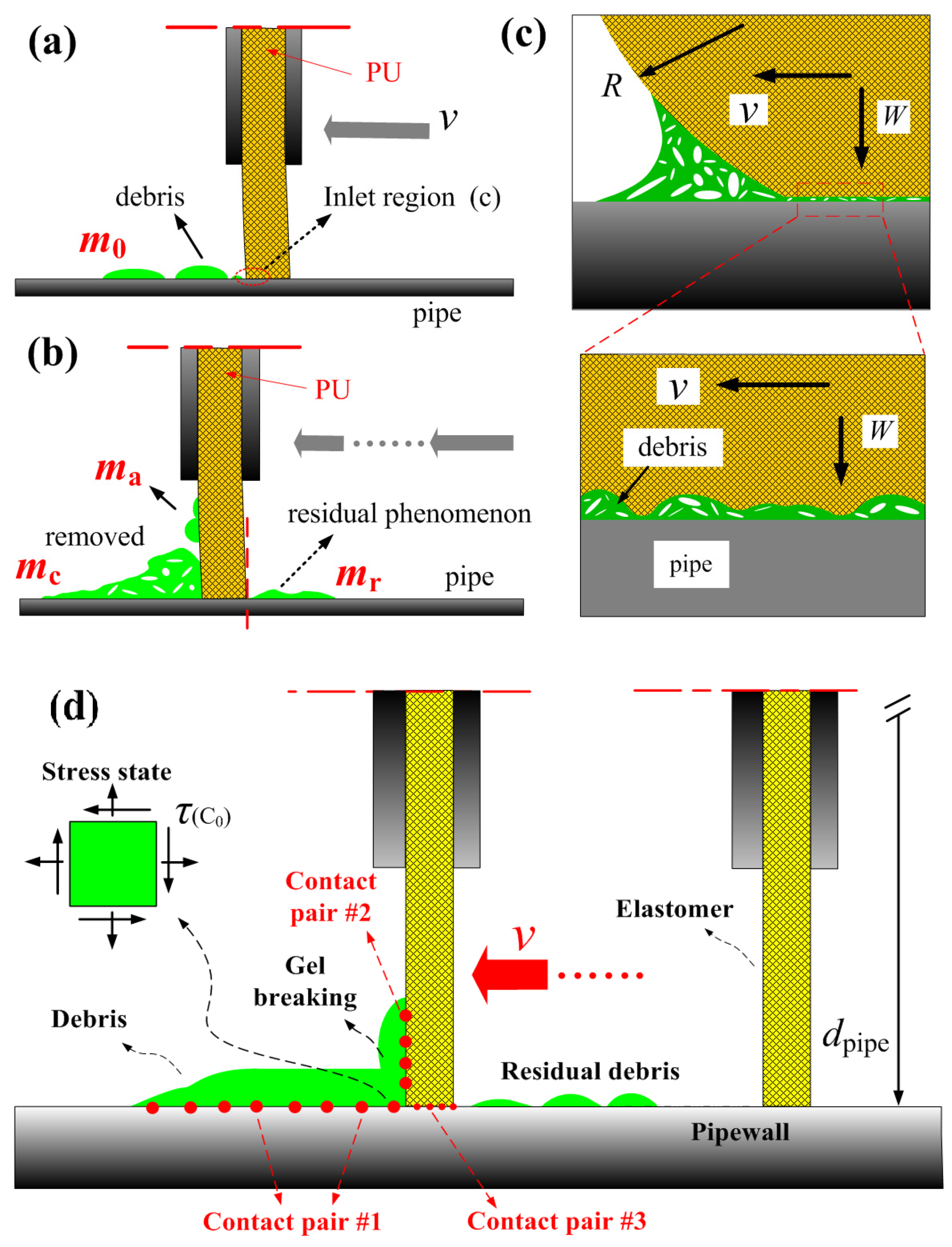
Rubber sealing discs have been shown in the past to have stick–slip frictional effects at the micro-scale and the macro-scale. In addition, the outer surface of rubber seals is composed of a chain of polymers, as shown in Figure 1c,d. Furthermore, investigations on the soft lubrication effect between the rubber seals of in-pipe robots help us better understand the frictional process in offshore oil flowlines. Throughout our investigation, the term of debris material removal ratio (DRR), η, was used to evaluate the tribological process in the in-pipe robots [19]. As shown in Figure 2, it is defined as
where m0 is the nominal mass of the gel deposit ahead of the in-pipe robots before our test, and mr is the real debris residual material after the dewaxing testing of rubber seals. This also suggests that estimating (even approximately) the contributions to the debris material removal ratio may not capture the correct physical or chemical properties of the wax–oil gel. In this process, the debris material removal ratio (DRR) can be expressed as
where vseals is speed of the rubber discs at the in-pipe robots, δwl is the thickness of the waxy gel deposition inside the steel pipe wall, E′ is the combined elastic modules at the elastomer/pipe contact, T′ is the nominal temperature field of crude oil at the in-pipe robot, and W is the load between the elastomer rubber seals and steel pipe wall.
η = (m0 − mr)/m0 × 100%
η = η(vseals, δwl, E′, T′, W)
In this study, the rubber seals play an extremely important role in providing safe supporting conditions for the in-pipe robots inside offshore pipelines. The failure of rubber seals could cause a blockage accident at the in-pipe robots inside offshore pipelines. While various studies have delved into the soft lubrication contact (solid–liquid multi-phase flow), the question of “what is the debris material removal rate (DRR) in the rubber seals of in-pipe robots?” has been rarely discussed, as shown in Figure 1 and Figure 2. It is critical to observe the dynamic behaviors of wax–oil gel breaking, which control the degree of danger of the in-pipe robots [19,20]. The work thus far has been confined to observations of dewaxing to support the concept of soft lubricating processes.
2. Materials and Experiment Methods
This section elucidates the principles of the dewaxing process in offshore pipelines. It simulates the soft lubrication in the mechanical dewaxing process during the operation of pipeline robots.
2.1. Soft Lubrication Testing Rig
The optical in situ observation experimental platform constructed in this study simulates the tribological process of in-pipe robots, as shown in Figure 3a. A self-developed testing rig is used for the frictional experiments. The specific details are as follows: (a) applying a constant load to the control rod of the wax-scraping elastic seals to ensure stability during the motion process; (b) considering the different reciprocating speeds in the experiment, using a servo motor; (c) an LED light is employed as the illumination system during the observation process, along with a portable microscope (SypereysTM A005 model; Shenzhen Deyufu Instrument Technology CO., Ltd., Shenzhen, China) as the image capture device. Details of the optical observations and the contact ratio measurements can be seen in Ref. [21].
Figure 3 shows the photos of the rubber sealing discs, steel pipes and waxy oil gel deposition used in the tribological experiments. The elastic modulus for the steel pipe wall and the rubber seals are 210 GPa and 12.4 MPa, respectively, and the Poisson’s ratios are 0.28 and 0.49. Before each soft frictional testing, the rubber discs and steel pipe samples were cleaned with ethanol to remove impurities and then thoroughly dried for each tribological testing. Figure 3 shows the three-dimension morphology of PU sealing discs, and the surface roughness Rq of the steel pipes and rubber discs were about 10.37 and 1.26 µm, respectively. The in-pipe robots included rubber sealing discs, inspection components and the connecting cables, as shown in Figure 1 and Figure 2. The elastomer sealing discs and rubbing speed were also the main influencing parameters in the wax-scraping applications. Therefore, various speeds (200 mm/min, 1000 mm/min, 2000 mm/min) were used to understand the effects. During the dewaxing process in the offshore pipelines, the waxy oil gel deposition was removed by the elastomer sealing disc, and the rubbing velocities of the seals ranged from a few mm/s in the pipelines to a few m/s in the waxy oil transportation pipelines.
2.2. Preparation of Gel Deposits and Experimental Methods
In order to obtain insight into the soft interface during the wax removal phenomenon, a model waxy gel deposition was studied using rubber sealing discs and the optical microscopy testing rig. The rubber seals testing rig simulated the waxy gel scraping process that occurs inside offshore pipelines. The setup of the rubber seals testing rig and the experimental details are described elsewhere in Ref. [21]. The soft frictional experiments quantify the compression and removal of waxy gel deposition in offshore pipe walls. Thus, knowledge of the soft lubrication or the dewaxing efficiency of waxy oil gel deposits was critical for the safe assurance of technology at offshore pipelines.
In preparation of the waxy oil gel deposition, we chose solid paraffin wax and crude oil (specifically, paraffin crude oil from the Daqing oilfield with a viscosity of 52.2 mPa·s at 20 °C) to create the model oil, simulating waxy gel deposition scenarios in crude oil fields [22,23]. The wax–oil mixture was formulated with 12.5% paraffin wax and 87.5% liquid oil. The experimental setup employed the soft lubricating model illustrated in Figure 3b,c to simulate the dewaxing process. The wax–oil mixture was injected into rough areas on the inner surface of the seals of the in-pipe robot.
3. Experimental Results
The fundamentals of soft interface and soft lubrication of in-pipe robots have not been investigated adequately. The wax scraping efficiency varied widely, which was determined by the elastomer sealing discs in robots and other physical parameters. Based on the obtained results in wax–oil gel breaking, it is conceivable to assume that the wax scraper method would be successfully controlled for pipeline cleaning.
3.1. Rubbing Contact between PU Seals and the Steel Pipe
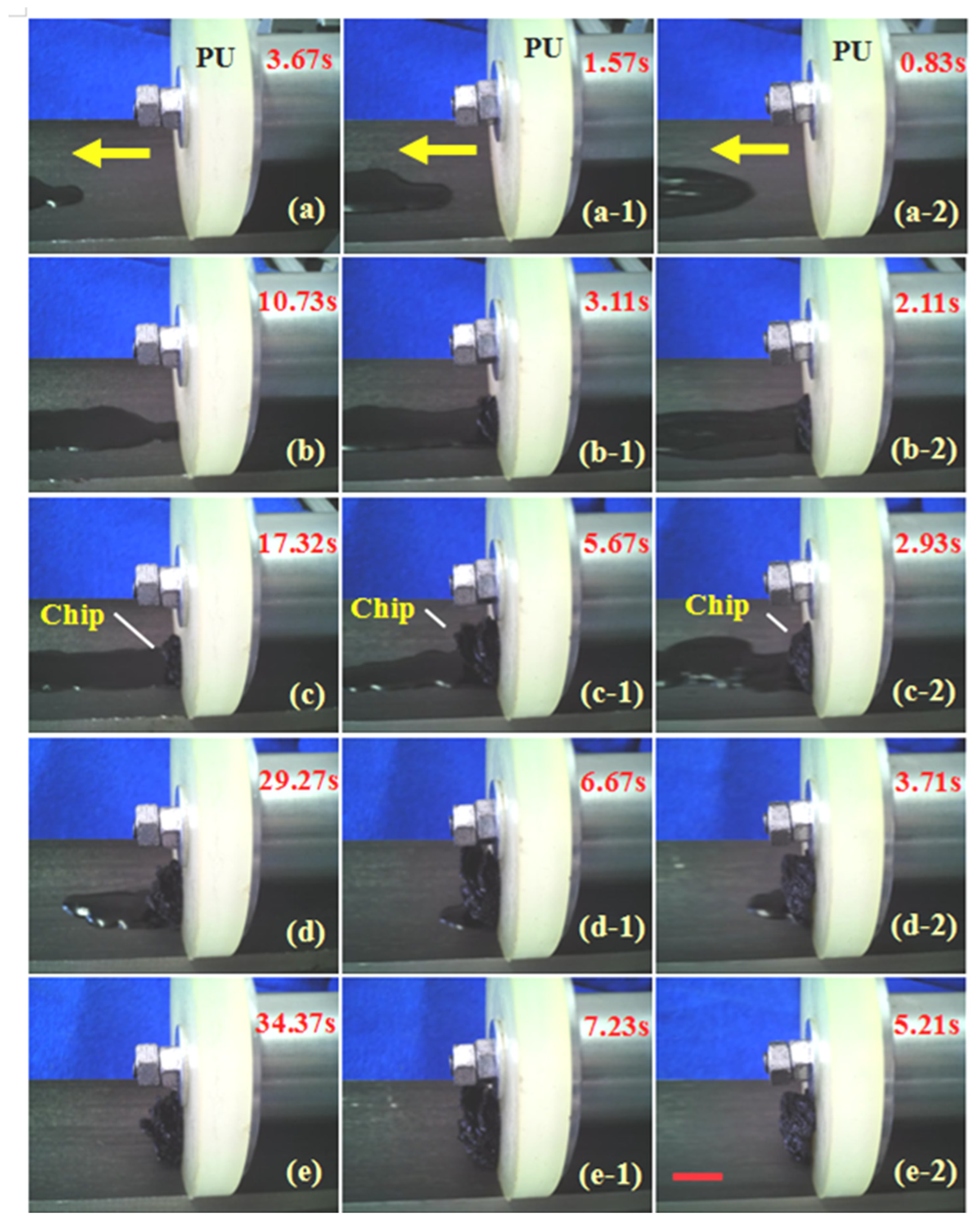
Figure 4a–l illustrate the dynamic process of wax–oil gel breaking at a sliding speed of 200 mm/min, and areas where gel breaking occurred are observed in Figure 4c–l. In these images of wax scraping (rubbing contact), three distinct areas are evident: the deposit compression area (contact location on the left rear), the soft interface (moving location on the right rear), and the gel-breaking front (entrance location of the soft interface). When the rubber sealing disc was moved, the waxy oil deposit was scraped from the pipe wall immediately. The gel deposition played an essential role in the soft lubrication situations. These three areas exhibited a clear interrelation in the soft frictional contact.
This phenomenon was observed, as shown in Figure 5, with the scraping speed of 2000 mm/min. A comparative study of the various rubbing speed was carried out. How are these gel-breaking chips formed? What is the effect of the soft interface between the rubber and steel pipes? To answer these questions, the gel-breaking process at soft lubrication will be investigated.
3.2. Dewaxing Process during Pure Sliding Contact
Based on the images in Figure 5 and Figure 6, the formation of gel breaking ahead of the soft interface is investigated. In Figure 6, the compressed area separates the gel-breaking region. As indicated in Figure 6(a-1), the friction force and gel-breaking force acting on the waxy oil gel deposition are given. The formation of waxy oil gel chips increases rapidly and then remains at a steady state in the rubber seals. As the PU sealing disc moves, the wax removal initiated by breaking fronts grows gradually, as shown in Figure 5(a–e,a-2–e-2). Increased moving speeds can cause the formation of waxy oil residual material. These results show that the gel-breaking process entails continuous brittle chip formations. However, the gel chips phenomenon in a steady state has no relation to the rubbing speed. Evidently, the effects of the wax contents and surface roughness of the elastomer during the wax debris gel breaking were ignored unfortunately.
3.3. Wax Scraping of Paraffin Deposits by Adding 25 wt% Solid Wax
Different waxy oil liquid environments can cause different contrasts. To explore the impact of wax deposition during the gel-breaking process, in this section, we conducted experiments to prepare depositions with a high wax content containing 25 wt% solid wax. We compared these high-wax-content gel depositions with the molds containing 12.5 wt% paraffin wax from the previous section. Additionally, we considered influencing factors, including the scraping speed.
However, the shapes of gel breaking in the different depositions varied. The dark black region of the gel-breaking front indicates the gradual detachment of the deposit. Such phenomenon was observed at a sliding speed of 200 mm/min, as seen in Figure 7a–l, and a similar occurrence was observed at 1000 mm/min, as seen in Figure 8a–l. When the sliding speed was increased to 2000 mm/min, clear instances of gel breaking and chip formation were prominently observed, as seen in Figure 9a–l. These results suggest that the wax removal phenomenon at the soft contact area is relatively strongly dependent on the debris characteristics and the aging effect of wax–oil depositions.
Here, we discuss the experiments performed on the waxy oil at the soft interface, prepared by the various solid wax content and gel depositions. Experiments were performed with a controlled wax content from 5 wt% up to 25 wt%. Between 12.5 wt% and 25 wt%, the wax deposition chip was observed, where friction on the rubber/steel interface was higher than on the waxy oil deposition.
3.4. Wax Pigging of Deposit Only Adding 5 wt% Solid Paraffin Wax
To understand the low wax content effect on debris removal, we conducted experiments with wax deposits adding only 5 wt% solid waxes. Figure 10 displays the relationship between the wax deposit properties (mainly, the wax content) and gel-breaking fronts when no oil flow is used in dynamic situations. Thus, debris accumulation on the sealing disc is shown in Figure 10(a,a-1,c,c-1). The applied load was 12 N. The strong dependence of friction on the rubber disc was probably due to the presence of solid wax at the soft contact area. However, the dewaxing process involves deep scientific puzzles. This paper deals with the debris residual model in gel-breaking processes, outlining the real contact ratio and soft lubrication. Quantitative results regarding the gel-breaking process will be mentioned in the discussion part.
4. Discussion
The mechanisms of soft lubrication need further analysis and elucidation for the in-pipe robot. In other words, a more in-depth quantitative study of the dewaxing process is required.
4.1. Effect of Contact Ratio at Soft Interface
The constant force mode for rubber sealing discs will influence the efficiency (η) in dewaxing, as presented in Equation (2), which may be oversimplified due to a poor understanding of the dewaxing mechanisms at the elastomer/pipe contact area. The failure in predictions of pigging efficiency has been linked with little understanding of the actual contact ratio. However, what is the influence of elastic rubber and its actual contact ratio? The contact ratio, α, is written as [24,25]
where A0 is the nominal contact area, and Ar is the real contact area in scraping rubber discs, as shown in the image processing in Figure 11. In addition, the real contact ratio could be understood using Hertz’s contact theory, which presented the nonlinear relationship with the force: α = Ar/A0 & W2/3. It is not surprising that this relationship has been debated during the last few years [25].
α = Ar/A0
In the current study, the elastomer rubber seals of the in-pipe robot were used. It is known that the real contact area is a significant factor for the tribological behavior of rubber seals. Our experiment obtained results from studies of optical measurements when no lubricate was used in the static situation (to the limits of our optical techniques). Figure 12 shows pictures of the real contact area between the glass plate and PU72 discs, where we chose a valley to observe its deformation. This is useful for insights into the sealing characteristics, resulting in the debris material residue phenomena.
In all the figures of Figure 12, the yellow region and the golden one indicate where the two surfaces do or do not have contact with each other, respectively. From Figure 12a–i, it can be observed that as the applied load gradually increases from 2 N to 12 N, the contact area also increases. The contact ratio even reaches 0.69 when the final load is 12 N.
The digital images of the real contact area between the glass disk and rubber discs is shown in Figure 11 and Figure 12, in which the different loads were applied. The variation in the real contact ratio under different elastic modules of the rubber specimen is shown in Figure 13. Hence, the random asperities in soft interfaces cause a much more complicated wax removal process. Using the soft sealing discs and an optimized debris material removal process, the chemical mechanical dewaxing process has been developed quickly. However, the ultimate waxy oil gel deposit material removal method is still unknown and developing. What is the debris material removal rate versus different rubber sealing materials?
4.2. Effect of DRR at the Rubber Discs
There are two core technical options for the dewaxing operations inside offshore pipelines, including wax scraping and melting the waxy gel deposit using heat. As the concentration of solid wax particles at the waxy oil gel deposition increases with time inside offshore pipelines due to aging, the waxy gel deposit becomes harder—i.e., the porosity of waxy gel deposit increases with time, as shown in Figure 10. Hence, the reliability of the waxy gel deposit scraping becomes increasingly difficult with time. As noted earlier, if the porosity and strength of the waxy oil gel deposit becomes too high, then the in-pipe robots may not be a safe and reliable option inside the steel pipelines. Moreover, knowledge of the soft interface of waxy oil gel depositions and the debris characteristics will be essential in choosing the appropriate way to remove the gel deposition.
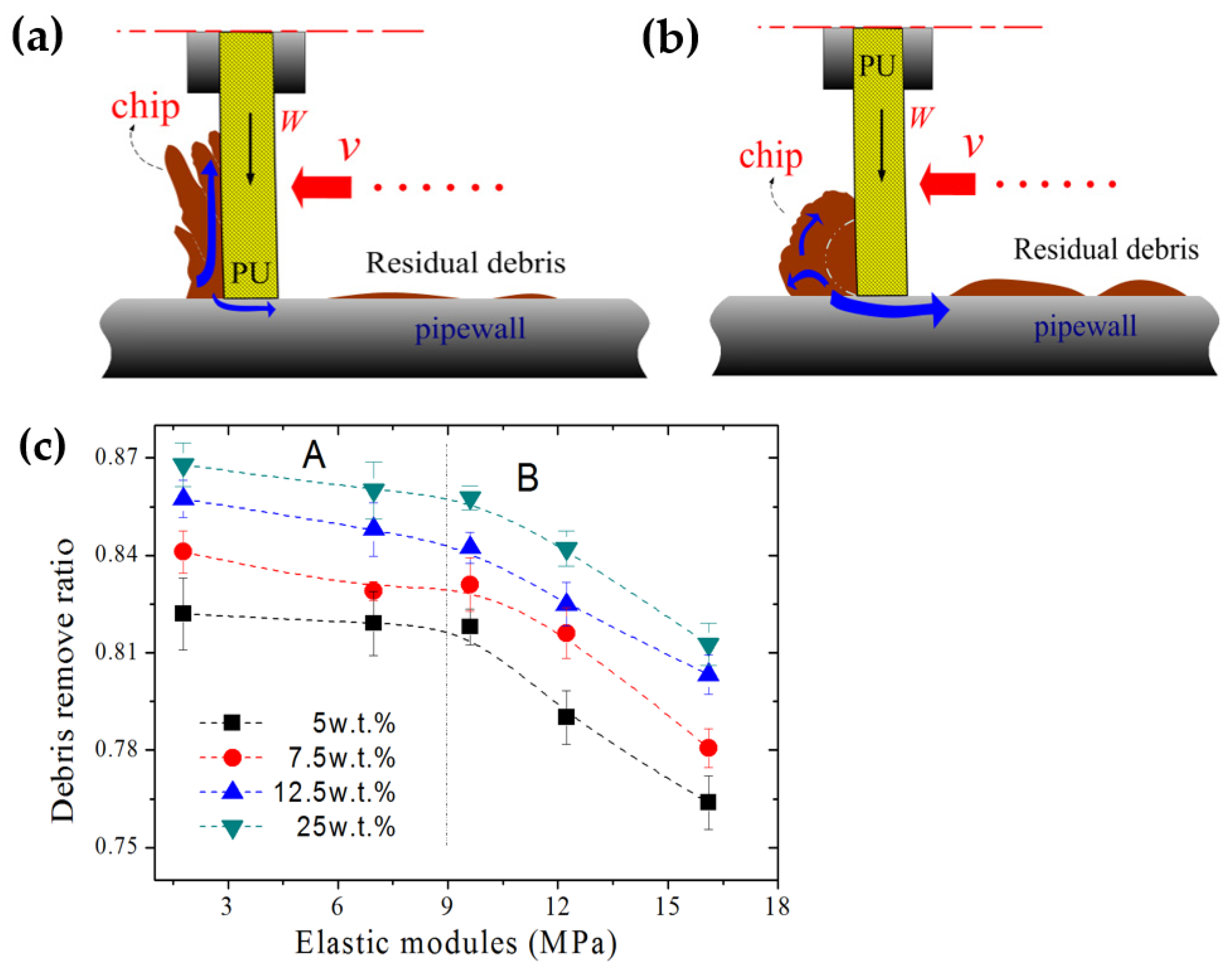
The rubber sealing disc determines the performance of the dewaxing process. However, the current tribological mechanism of sealing discs is far from perfect. Figure 14 shows the wax pigging efficiency as a function of elastic modules of various elastomer discs. The debris material removal rate (DRR) was measured five times for every gel deposition. It can be seen that the DRR of high wax content is larger than low wax content. Once a wax deposit detaches from a pipe wall, these parameters change over time, as indicated in Figure 2 and Figure 10. In this study, the Figure 2a–d schematically show the decreasing weight of debris. For the elastomer disc less than 8.9 MPa in elastic modules, the removal ratio of PU exists in a steady state (~0.83). For the hardest PU disc, the removal ratio of gel deposit (just adding 5 w.t.% solid wax) is ~0.76. This phenomenon is of particular interest as imposing soft-contact dependency on the dewaxing process can have a profound impact on the wax pigging frequency.
4.3. Effect of Gel-Breaking Forces at the In-Pipe Robots
In this work, a model waxy oil gel deposition has been used to simulate the debris inside steel pipe walls. Since the waxy oil gel formed inner the steel pipe has a limited thickness, the gel-scraping phenomenon could be captured at various rubbing speeds. Based on the orthogonal cutting theory, we proposed a model to predict the cutting force of debris [26]. And, details of the frictional force of in-pipe robots are given as follows:
where, f, Fm, n and W are the frictional coefficient of rubber seals, the horizontal force, the number of rubber seals and the load (as shown in Figure 6(a-1) and Figure 14), respectively [27,28,29]. The above formula is an critical achievement of tribological technology as it could be used to overcome a series of sealing problems in in-pipe robots (friction, wear, leakage and so forth) qualitatively. Therefore, it should be presented that
where the terms dpipe, δwl and τ(C0) are the cross-section size of steel pipelines, the thickness of the waxy gel deposition, and the yield stress of the waxy gel, as shown in Figure 14. And, C0 represents the porosity of gel deposits. Evidently, the waxy gel breaking force, Fwrf, is varied in terms of its linear correlation with the yield stress and the thickness of waxy gel depositions (τ(C0), δwl). Simple equilibrium considerations are as follows:
and substituting Equations (4) and (5) in Equation (6) and rearranging them provides the following:
where K = π·dpipe·η·τ(C0). Many parameters, including the dewaxing efficiency, aging effect of the gel deposition and the wax contents, potentially affect the frictional and reliability behavior of the in-pipe robots. The soft lubrication of rubber seals is an important problem in the design and operation of various in-pipe robots in offshore pipelines. Although there are certain differences between the (δwl)l values taken from the theoretical Equations (5) and (7), it has been found that Equation (7) can qualitatively demonstrate the theoretical relationships between the gel-breaking force and thickness of the waxy gel layer. There is a need to establish an appropriate relationship defining the soft interface (dewaxing) for the rubber seals. However, the frictional forces are significantly affected when a wax blockage phenomenon occurs. The aim of experimental tests is to be able to predict the responses of in-pipe robots.
Fm = (Fhyst + Fadh) = n·f·W
Fwrf = (δwl)l·π·dpipe·η·τ(C0)
Ftotal(t) = Fwrf + Fm = (δwl)l·π·dpipe·η·τ(C0) + (Fhyst + Fadh)
Ftotal(t) − Fm = Ftotal(t) − n·f·W
={π·dpipe·η·τ(C0)}·(δwl)l = K·(δwl)l
={π·dpipe·η·τ(C0)}·(δwl)l = K·(δwl)l
As seen in Equation (7), the gel-breaking force, Fwrf(t), for rubber seals is dependent on the gel deposition and geometrical parameters (τ(C0), η, C0) as well as the operating conditions (dpipe, n). From Equation (7), plotting the quantity (Ftotal(t) − n·f·W) against the thickness of the waxy gel layer, (δwl)l, would result in a straight line, with slope K. Although Ftotal(t) and W could be directly measurable, in general, the frictional coefficient is complex. In the previous work, f was measured by the tribo-meter independently, and Equation (7) was employed to measure the gel-breaking strength of the wax layer. The frictional force was determined by the thickness of the waxy gel layer between the rubber seals and pipe wall [30,31,32,33]. In field in-pipe robot operations, the situations become totally different. The scraped gel chips are accumulated ahead of the elastomer rubber seals inside the steel pipelines, as shown in Figure 1. More quantitative studies will undoubtedly result in improvements of the capability of in-pipe robot operations.
5. Conclusions
The frictional performance of rubber sealing discs was studied for in-pipe robots inside subsea pipelines. The main conclusions are summarized as follows:
- The friction testing results showed that under room temperature conditions and a loading of 12 N, the gel deposition removal between elastomer rubber and steel pipes is determined by the evolution of gel-breaking instability. Moreover, based on this study, it seems that the scraping velocities do not have an essential effect on the debris material removal ratio. However, the pigging velocity of pipe robots has a determining effect on the economic costs of pipelines, and the probability of wax slugs being formed is increased.
- It is found that the pipe robot with softer rubber seals showed a better synergistic effect with the dewaxing process. However, the reliability of the wax removal becomes increasingly difficult with time as the hardness and the strength of waxy oil gel depositions become too high. This investigation may be helpful to choose the high-reliability rubber seals and develop an intelligent pigging scheme for in-pipe robots.
- Soft interfacial behavior at wax–oil gel environments was confirmed to play an important role in the tribo-failure of elastomer discs. These findings observed in this study are useful for better understanding the friction behavior of pipe robots and how the blockage accident phenomenon of rubber seals forms in the soft contact region at the in-pipe robots.
Author Contributions
Conceptualization, G.T., Z.L., Y.J. and X.H.; methodology, G.T.; investigation, G.T.; writing—original draft preparation, G.T., Z.L. and Y.J.; writing—review and editing, all; supervision, G.T.; project administration, G.T.; funding acquisition, G.T. and X.H. All authors have read and agreed to the published version of the manuscript.
Funding
The authors gratefully acknowledge the National Natural Science Foundation of China (52105176, 51375495, 51175514), the Science Foundation of China University of Petroleum, Beijing (Nos. 2462013YXBS008), the Basic and Applied Basic Research Foundation of Guangdong Province (Grants No. 2023B1212010012, 2022A1515240004) and the Program for Guangdong Introducing Innovative and Entrepreneurial Teams (2019BT02Z393).
Data Availability Statement
Data are contained within the article.
Conflicts of Interest
Author Xing Huang was employed by the Guangzhou Mechanical Engineering Research Institute Co., Ltd. The remaining authors declare that the research was conducted in the absence of any commercial or financial relationships that could be construed as a potential conflict of interest.
References
- Yao, B.C.; He, Z.C.; Lu, N.; Zhang, S.M. A novel PIG and an intelligent pigging scheme based on deep-learning technology. Int. J. Pres. Ves. Pip. 2022, 200, 104803. [Google Scholar] [CrossRef]
- Mohd, Z.A.R.; Mohd, F.M.Y.; Sheikh, A.Z.S.S.; Mamat, N.; Putra, S.M.S.M.; Roslan, S.A. Modeling of the in-pipe inspection robot: A comprehensive review. Ocean Eng. 2020, 203, 107206. [Google Scholar]
- Kahnamouei, J.T.; Moallem, M. A comprehensive review of in-pipe robots. Ocean Eng. 2023, 277, 114260. [Google Scholar] [CrossRef]
- Amit, S.; Hamad, K. Application of robotics in offshore oil and gas industry-A review, Part II. Robot. Auton. Syst. 2016, 75, 508–524. [Google Scholar]
- Yang, C.J.; Liu, S.Y.; Su, H.; Zhang, L.N.; Xia, Q.C.; Chen, Y.H. Review of underwater adsorptive-operating robots: Design and application. Ocean Eng. 2024, 294, 116794. [Google Scholar] [CrossRef]
- Tang, C.; Du, B.Y.; Jiang, S.W.; Shao, Q.; Dong, X.G.; Liu, X.J.; Zhao, H.C. A pipeline inspection robot for navigating tubular environments in the sub-centimeter scale. Sci. Robot. 2022, 7, eabm8597. [Google Scholar] [CrossRef] [PubMed]
- Chen, J.H.; Luo, X.M.; Zhang, H.L.; He, L.M.; Chen, J.P.; Shi, K.Y. Experimental study on movement characteristics of bypass PIG. J. Nat. Gas Sci. Eng. 2018, 59, 212–223. [Google Scholar] [CrossRef]
- Lai, Z.; Xu, J.; Bowen, C.R.; Zhou, S. Self-powered and self-sensing devices based on human motion. Joule 2022, 6, 1501–1565. [Google Scholar] [CrossRef]
- Zhang, H.; Gao, M.Q.; Tang, B.; Cui, C.; Xu, X.F. Dynamic characteristics of the pipeline inspection gauge under girth weld excitation in submarine pipeline. Petrol. Sci. 2022, 19, 774–788. [Google Scholar] [CrossRef]
- Zhang, H.; Dong, J.H.; Cui, C.; Liu, S.H. Stress and strain analysis of spherical sealing cups of fluid-driven pipeline robot in dented oil and gas pipeline. Eng. Fail. Anal. 2020, 108, 104294. [Google Scholar] [CrossRef]
- Zhang, H.; Zhang, S.M.; Liu, S.H. Chatter vibration phenomenon of pipeline inspection gauges (PIGs) in natural gas pipeline. J. Nat. Gas Sci. Eng. 2015, 27, 1129–1140. [Google Scholar] [CrossRef]
- Chen, Z.; Qiu, X.; Yang, L. Deformation and stress analysis of cup on pipeline inspection gauge based on reverse measurement. Energy Sci. Eng. 2022, 10, 2509–2526. [Google Scholar] [CrossRef]
- Zhang, X.; Huang, Q.Y.; Zhang, Y.; Wang, K.; Chen, W.; Wang, Y.J.; Liu, Y.M.; Zhang, D.X.; Chen, C.H. Continuous flow of fractured wax deposits in subsea pipelines. Non-Newton. Fluid Mech. 2023, 311, 104967. [Google Scholar] [CrossRef]
- Zhang, X.; Huang, Q.Y.; Chen, W.; Zhang, Y.; Gao, X.D.; Liu, Y.M.; Wang, Y.J. Field pigging modeling for predicting wax breaking force and wax removal efficiency of disk PIG. SPE J. 2022, 7, 3864–3883. [Google Scholar] [CrossRef]
- Gong, J.; Zhang, Y.; Liao, L.; Duan, J.; Wang, P.; Zhou, J. Wax deposition in the oil/gas two-phase flow for a horizontal pipe. Energy Fuels 2011, 25, 1624–1632. [Google Scholar] [CrossRef]
- Dong, J.H.; Zhang, H.; Liu, S.H. 3D-printed bio-inspired sealing disc of pipeline inspection gauges (PIGs) in small diameter pipeline. J. Nat. Gas Sci. Eng. 2019, 61, 344–356. [Google Scholar] [CrossRef]
- Fan, K.F.; Si, L.; Li, W.D. Experimental study on the wax deposit properties in the crude oil pipeline: Crystal morphology, yield stress. Petro. Sci. Technol. 2022, 40, 2737–2754. [Google Scholar] [CrossRef]
- Scaraggi, M.; Angerhausen, J.; Dorogin, L.; Murrenhoff, H.; Persson, B.N.J. Influence of anisotropic surface roughness on lubricated rubber friction: Extended theory and an application to hydraulic seals. Wear 2018, 410–411, 43–62. [Google Scholar] [CrossRef]
- Tan, G.B.; Liu, S.H.; Wang, D.G.; Zhang, S.W. Tribological behaviors of wax-in-oil gel deposition in orthogonal cleaning process. Tribol. Lett. 2015, 57, 16. [Google Scholar] [CrossRef]
- Wang, Q.; Sarica, C.; Volk, M. An experimental study on wax removal in pipes with oil flow. J. Energy Resour. Technol. 2008, 130, 130–134. [Google Scholar] [CrossRef]
- Tan, G.B.; Huang, X.; Gao, J.X.; Zhang, Y.K.; Tian, Y.C. Analysis of in-situ testing technology and equipment for the large deformation frictional contact with compliant elastomer. Tribology 2022, 42, 187–201. [Google Scholar]
- Bai, C.Y.; Zhang, J.J. Effect of carbon number distribution of wax on theyield stress of waxy oil gels. Eng. Chem. Res. 2013, 52, 2732–2739. [Google Scholar] [CrossRef]
- Bai, C.Y.; Zhang, J.J. Thermal, macroscopic, and microscopic characteristics of wax deposits in field pipelines. Energy Fuels 2013, 27, 752–759. [Google Scholar] [CrossRef]
- Sahli, R.; Pallares, G.; Papangelo, A.; Ciavarella, M.; Ducottet, C.; Ponthus, N.; Scheibert, J. Shear-induced anisotropy in rough elastomer contact. Phys. Rev. Lett. 2019, 122, 214301. [Google Scholar] [CrossRef] [PubMed]
- Liang, X.M.; Xing, Y.Z.; Li, L.T.; Yan, D.; Wang, G.F. An experimental study on the relation between friction force and real contact area. Sci. Rep. 2021, 11, 20366. [Google Scholar] [CrossRef] [PubMed]
- Caprino, G.; Nele, L.; Santo, L. Effect of tool wear on cutting forces in the orthogonal cutting of unidirectional glass fibre-reinforced plastics. Appl. Sci. Manuf. 1996, 27, 409–415. [Google Scholar] [CrossRef]
- Zhu, X.X.; Wang, W.; Zhang, S.M.; Liu, S.H. Experimental research on the frictional resistance of fluid-driven pipeline robot with small size in gas pipeline. Tribol. Lett. 2017, 65, 47. [Google Scholar] [CrossRef]
- Scaraggi, M.; Dorogin, L.; Angerhausen, J.; Persson, B.N.J. Elastohydrodynamics for soft solids with surface roughness: Transient effects. Tribol. Lett. 2017, 65, 95. [Google Scholar] [CrossRef]
- Zhou, Z.Y.; Zhang, K.; Zhou, Q.; Qin, K.; Ling, X.; Sun, W.H.; Yuan, T.X. In-situ observation of particles invasion behavior into the sealing interface under vibration. Measurement 2023, 214, 112811. [Google Scholar] [CrossRef]
- Li, W.D.; Huang, Q.Y.; Wang, W.D.; Dong, X.; Gao, X.; Hou, L. Estimating the wax breaking force and wax removal efficiency of cup PIG using orthogonal cutting and slip-line field theory. Fuel 2019, 236, 1529–1539. [Google Scholar] [CrossRef]
- Zhang, H.; Zhang, S.M.; Liu, S.H.; Wang, Y. Collisional vibration of PIGs (pipeline inspection gauges) passing through girth welds in pipelines. J. Nat. Gas Sci. Eng. 2017, 37, 15–28. [Google Scholar] [CrossRef]
- Liu, S.J.N.; Liu, S.H.; Xiao, H.P. Optimization of structural parameters of jet end in the underwater intelligent pigging robot. Ocean Eng. 2020, 216, 108092. [Google Scholar] [CrossRef]
- Chang, L.; Cao, Y.G.; Chen, J.Z.; Dai, C.L.; He, R.Y.; Zhou, Z.G. The blockage risk in the elbow of the Bi-directional pig used for submarine pipeline based on the modified Burgers-Frenkel (MB-F) model. Ocean Eng. 2023, 268, 113508. [Google Scholar] [CrossRef]
Figure 1.
Common problems of the in-pipe robot in offshore pipelines, showing the interaction of the rubber/pipe interface. (a) The subsea production system, (b) the wax deposition, in-pipe robots inside the pipe wall, (c) main construction of the in-pipe robots, (d) three-dimensional models of rubber sealing disc in the steel pipeline.
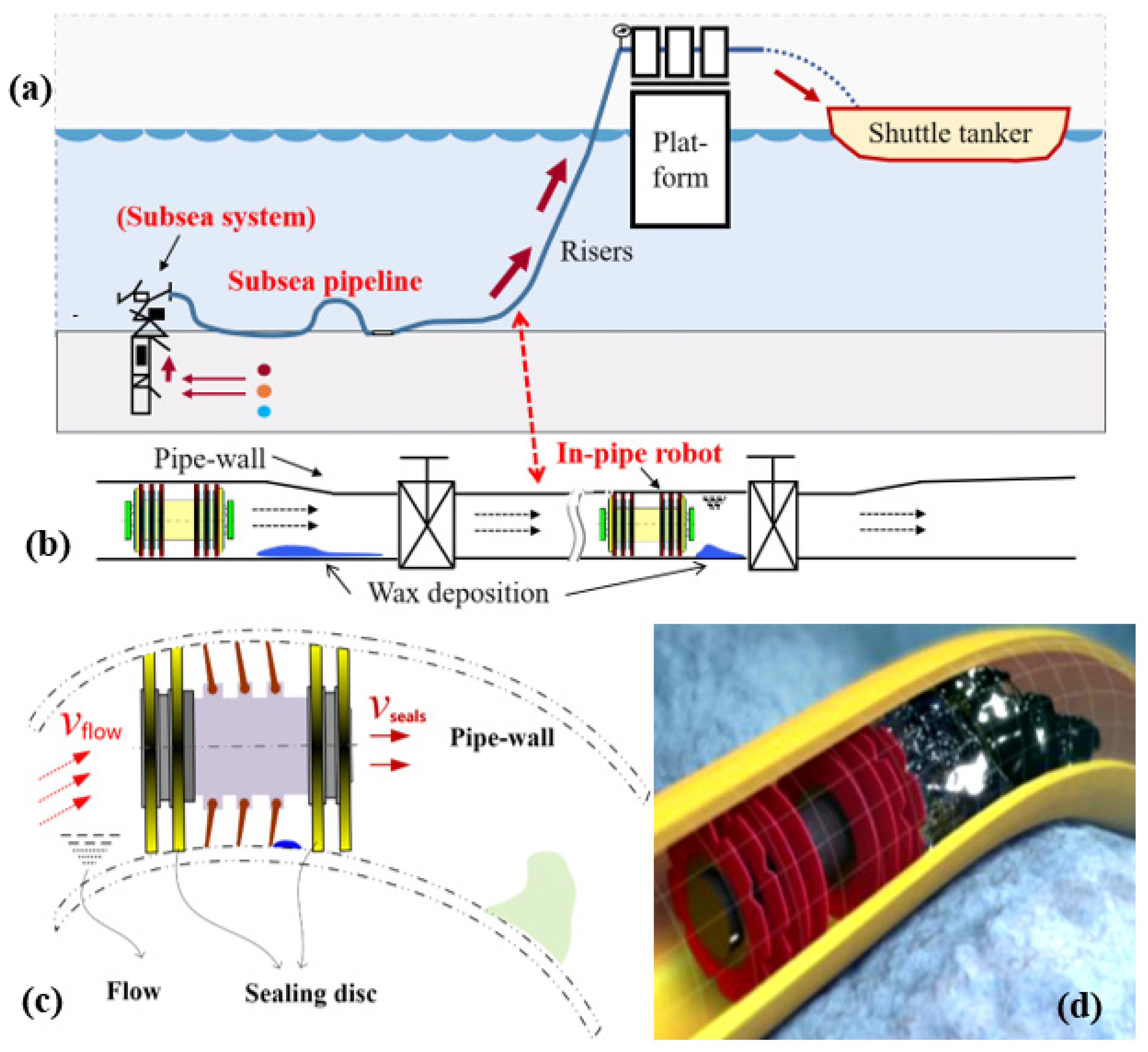
Figure 2.
Lubricating interface and its debris material removal ratio (DRR). (a) Waxy oil depositions ahead of rubber sealing disc and its rubbing contact, and mass of all debris is m0. (b) Wax scraping failure with the dangerous debris residual material phenomenon, mr. And, the build-up debris of adhesion to rubber disc is ma. (c) The inlet regions at lubricated, compliant contact. (R, radius of rubber surface in the worn seals). (d) The different contact pairs at soft lubricating area.

Figure 3.
Schematic diagram of the soft frictional testing rig in (a). And, (b) the real-time observation setup at the different contact pairs. (c) The force analysis of the rubber sealing disc. (d) Three-dimension morphology of PU disc. Specifically, in (a), prior to switching portable microscopy for optical microscopy (in dark red colors, facing upward to the actual contact regions), the optical windows in the rigid steel pipe specimen are replaced with transparent glass specimens.
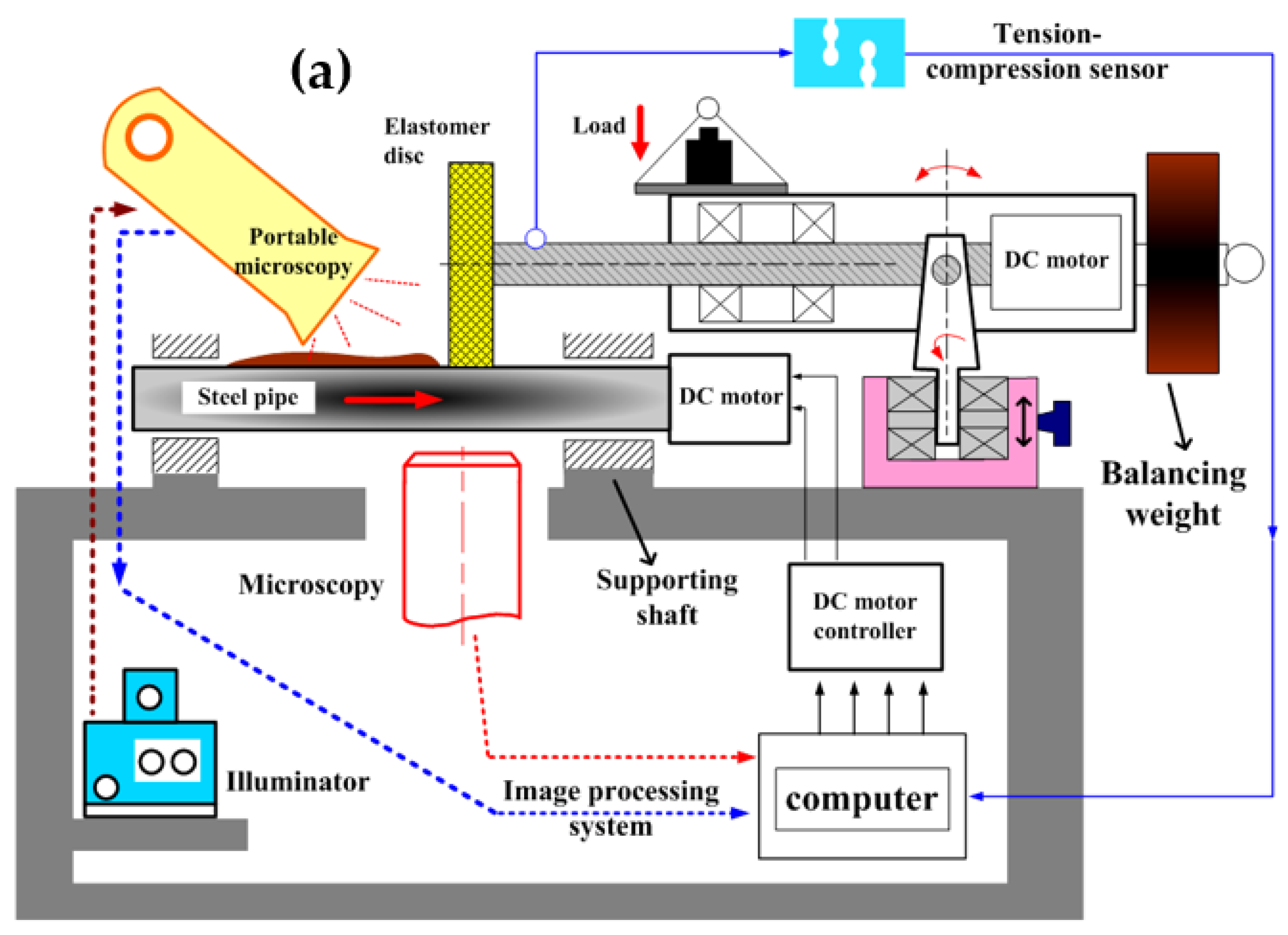

Figure 4.
Waxy oil chip phenomenon at soft contact of the rubber sealing discs. (a–l) are images of the gel-breaking process of the oil deposit mold. (Sliding speed: 200 mm/min, 12.5 wt% solid wax).
Figure 4.
Waxy oil chip phenomenon at soft contact of the rubber sealing discs. (a–l) are images of the gel-breaking process of the oil deposit mold. (Sliding speed: 200 mm/min, 12.5 wt% solid wax).
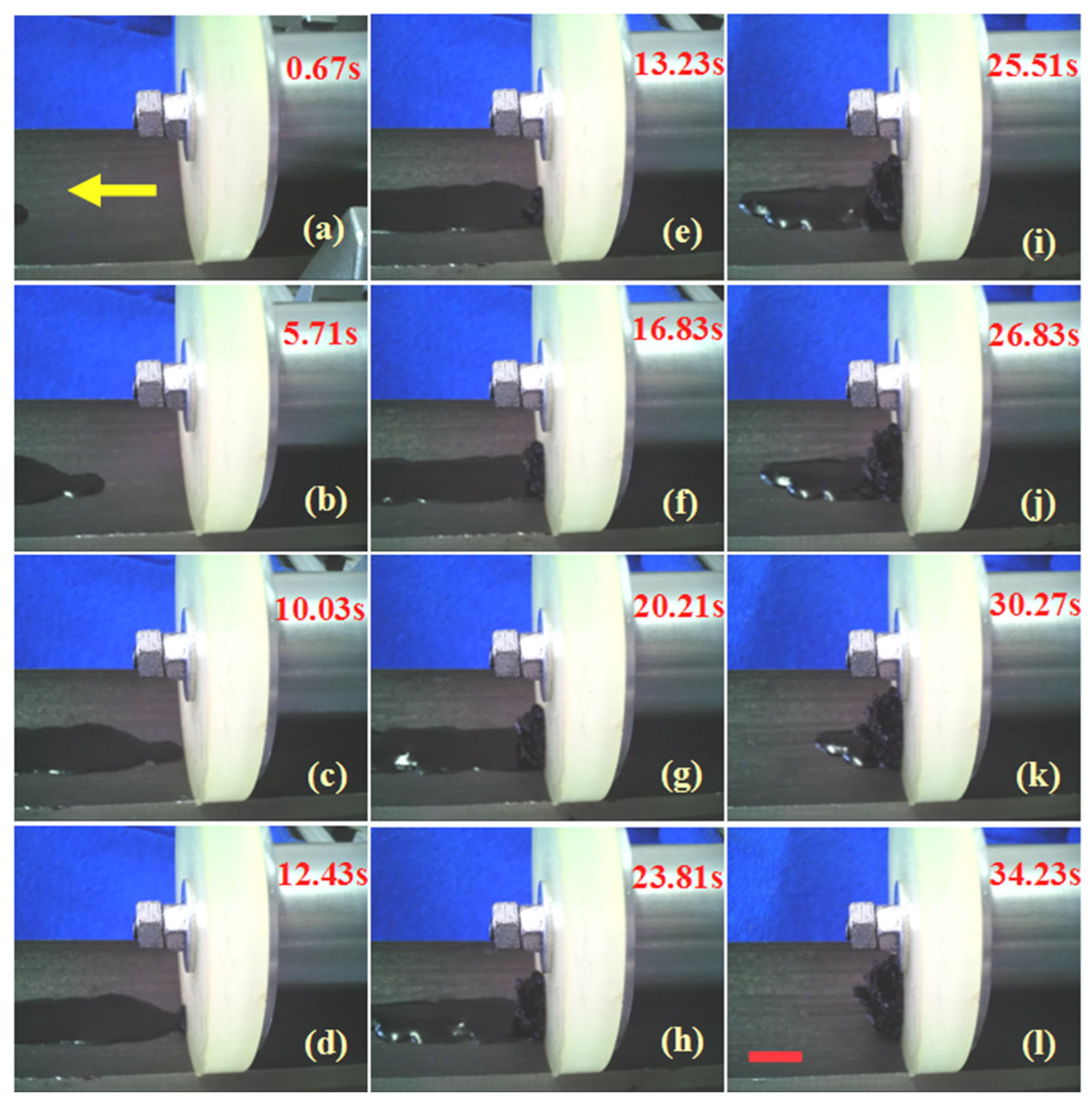
Figure 5.
Dynamic frictional process in wax scraping of the rubber sealing discs at different rubbing speeds. Speed: (a–e) is 200 mm/min; (a-1–e-1) is 1000 mm/min; (a-2–e-2) is 2000 mm/min. Waxy oil gel depositions adding 25 wt% solid wax particles.
Figure 5.
Dynamic frictional process in wax scraping of the rubber sealing discs at different rubbing speeds. Speed: (a–e) is 200 mm/min; (a-1–e-1) is 1000 mm/min; (a-2–e-2) is 2000 mm/min. Waxy oil gel depositions adding 25 wt% solid wax particles.

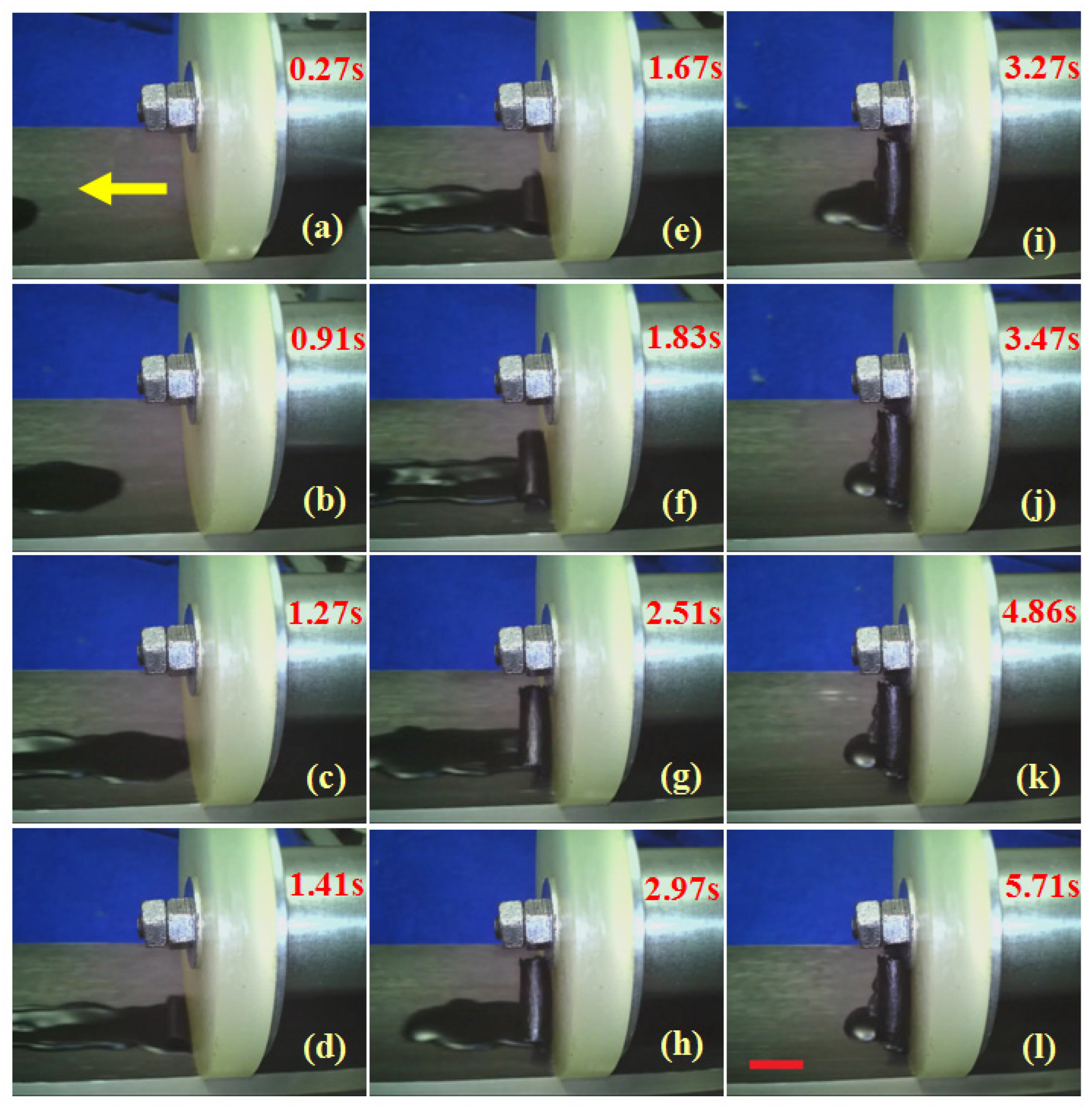
Figure 6.
The process of gel-breaking chip formation under the soft tribological conditions. (a–d) the gel-breaking chips evolution between rubber disc and pipe. (a-1–b-1) the friction force and gel-breaking force are given. And, (c-1–d-1) The arrow (in blue) indicates the complex flow of waxy oil gel chips during the scraping process. The solid wax content of gel deposition may also cause a different loading dependence.
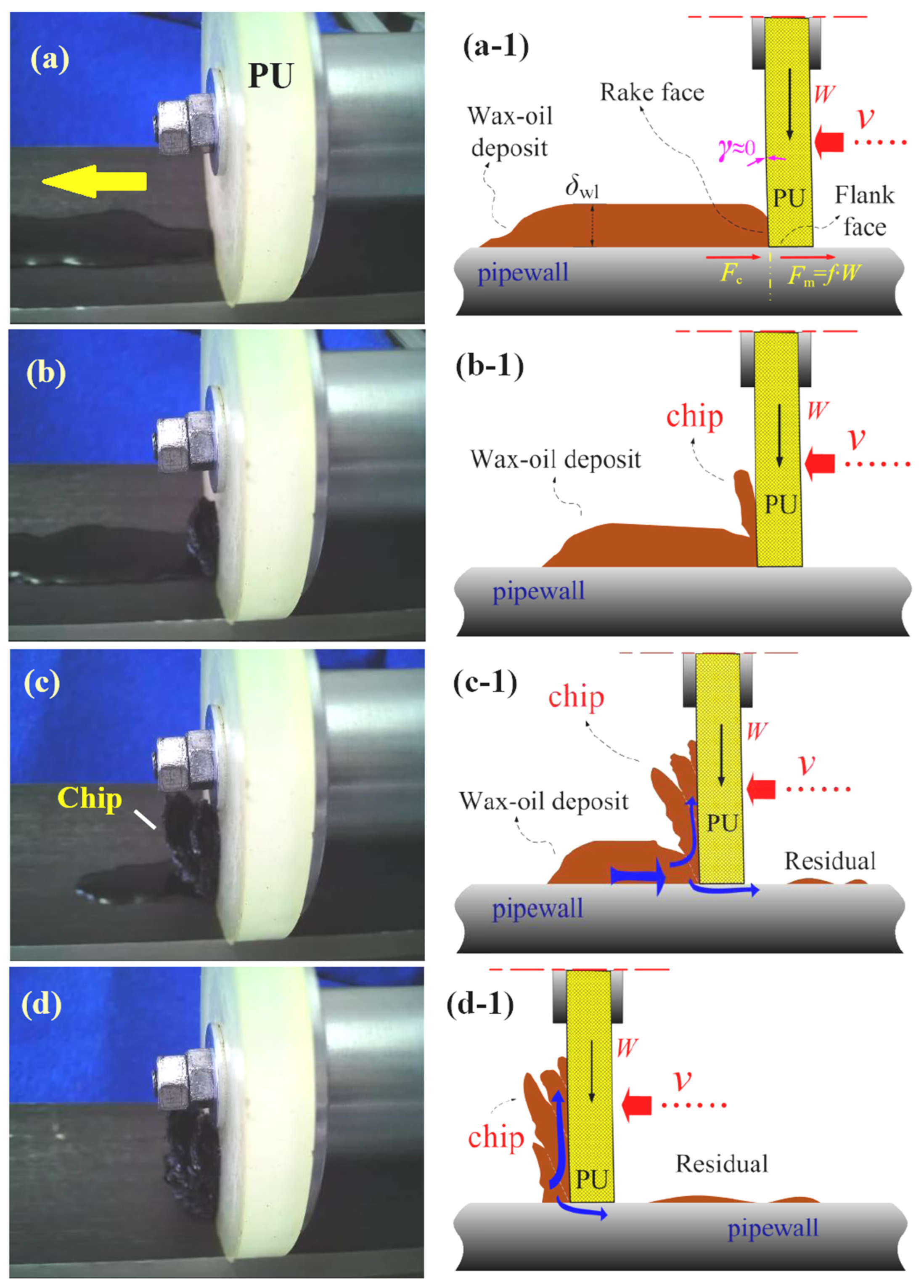
Figure 7.
Images of gel debris chip formation during the wax-scraping process. (a–l) is mold deposit adding 25 wt% solid wax. Scraping speed: 200 mm/min. Normal squeezing load: 12 N.
Figure 7.
Images of gel debris chip formation during the wax-scraping process. (a–l) is mold deposit adding 25 wt% solid wax. Scraping speed: 200 mm/min. Normal squeezing load: 12 N.
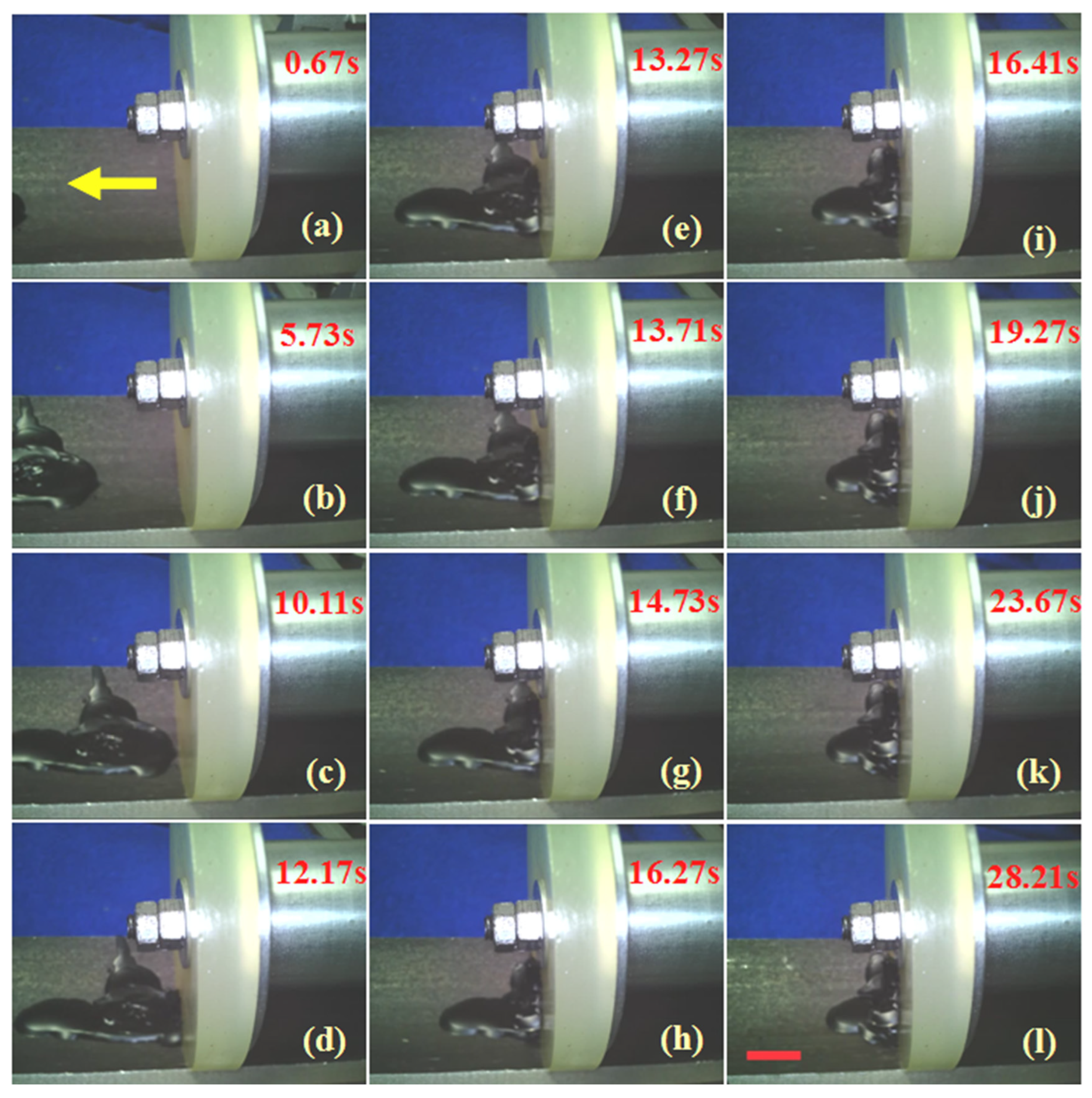
Figure 8.
Images of gel debris during wax-scraping process at much larger sliding speed in our test rig. (a–l) is mold deposit adding 25 wt% solid wax. Scraping speed: 1000 mm/min. Normal squeezing load: 12 N.
Figure 8.
Images of gel debris during wax-scraping process at much larger sliding speed in our test rig. (a–l) is mold deposit adding 25 wt% solid wax. Scraping speed: 1000 mm/min. Normal squeezing load: 12 N.

Figure 9.
Images of wax debris chip formations during scraping process. (a–l) is mold deposit adding 25 wt% solid wax. Scraping speed: 2000 mm/min. Normal squeezing load: 12 N.
Figure 9.
Images of wax debris chip formations during scraping process. (a–l) is mold deposit adding 25 wt% solid wax. Scraping speed: 2000 mm/min. Normal squeezing load: 12 N.

Figure 10.
Images of scraped waxy oil gel debris with the different wax contents (using waxy crude oil and solid paraffin wax, respectively). (a,a-1) represent the waxy oil gel with 5 wt% solid wax; (b,b-1) represent waxy oil gel with 12.5 wt% solid wax; (c,c-1) represent waxy oil gel with 25 wt% solid wax.

Figure 11.
Color image of the real contact area of sealing disc in (a), and the corresponding binarized digital image after the post-processing methods in (b).
Figure 11.
Color image of the real contact area of sealing disc in (a), and the corresponding binarized digital image after the post-processing methods in (b).
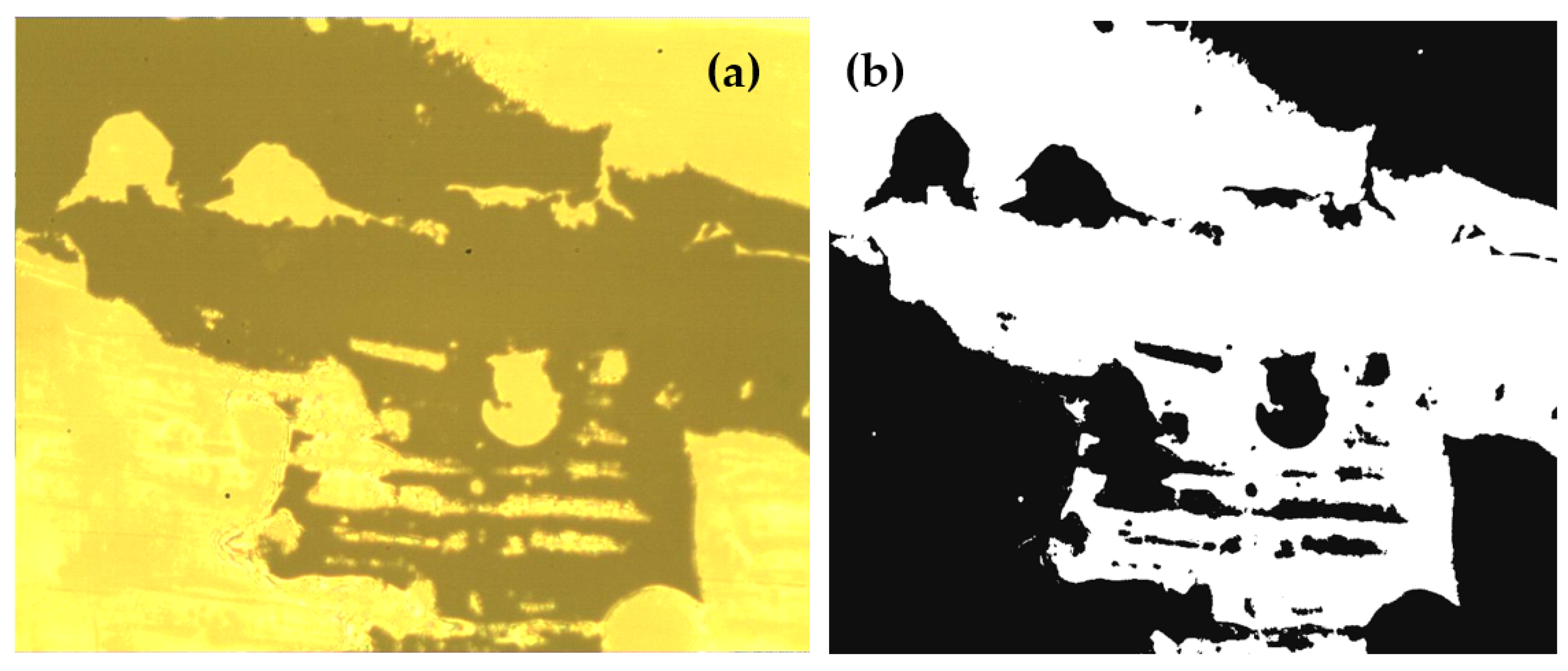
Figure 12.
Contact region under different load: (a) 2 N, (b) 3 N, (c) 4 N, (d) 5 N, (e) 6 N, (f) 8 N, (g) 9 N, (h) 10 N and (i) 12 N. Material: PU72. Scale bar shown in (i) is 200 µm.
Figure 12.
Contact region under different load: (a) 2 N, (b) 3 N, (c) 4 N, (d) 5 N, (e) 6 N, (f) 8 N, (g) 9 N, (h) 10 N and (i) 12 N. Material: PU72. Scale bar shown in (i) is 200 µm.
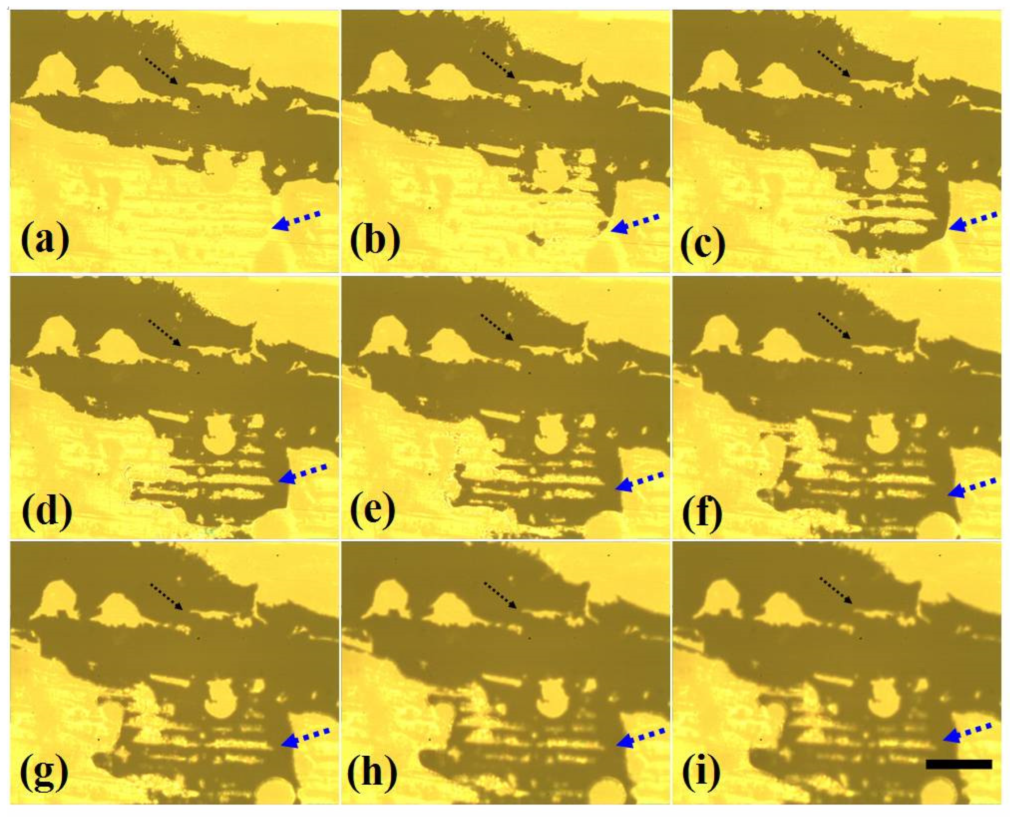
Figure 13.
Real contact ratio versus elastic modules under various normal loading.

Figure 14.
Soft lubricating interfaces and their debris material removal ratio versus elastic modules of different sealing discs in (c). Scraping speed: 1000 mm/min. Load: 12 N. The bright blue arrows in (a,b) indicate the complicated interface and the residual debris flow in the rough soft contact.

Disclaimer/Publisher’s Note: The statements, opinions and data contained in all publications are solely those of the individual author(s) and contributor(s) and not of MDPI and/or the editor(s). MDPI and/or the editor(s) disclaim responsibility for any injury to people or property resulting from any ideas, methods, instructions or products referred to in the content. |
© 2024 by the authors. Licensee MDPI, Basel, Switzerland. This article is an open access article distributed under the terms and conditions of the Creative Commons Attribution (CC BY) license (https://creativecommons.org/licenses/by/4.0/).
Share and Cite
MDPI and ACS Style
Tan, G.; Luo, Z.; Ji, Y.; Huang, X. Friction Performance of Rubber Sealing Disc Inside Pipe Robots for the Production of High-Paraffin Oil. Lubricants 2024, 12, 102. https://doi.org/10.3390/lubricants12030102
AMA Style
Tan G, Luo Z, Ji Y, Huang X. Friction Performance of Rubber Sealing Disc Inside Pipe Robots for the Production of High-Paraffin Oil. Lubricants. 2024; 12(3):102. https://doi.org/10.3390/lubricants12030102
Chicago/Turabian StyleTan, Guibin, Ziwei Luo, Yifan Ji, and Xing Huang. 2024. "Friction Performance of Rubber Sealing Disc Inside Pipe Robots for the Production of High-Paraffin Oil" Lubricants 12, no. 3: 102. https://doi.org/10.3390/lubricants12030102
Note that from the first issue of 2016, this journal uses article numbers instead of page numbers. See further details here.