Article

Study of the Effect of Static Eccentricity on Vibration Damping Properties of Squeeze Film Dampers Considering the Two-Phase Flow Case

1
School of Aeroengine, Shenyang Aerospace University, Shenyang 110136, China
2
AECC South Industry Company Limited, Zhuzhou 412002, China
*
Author to whom correspondence should be addressed.
Lubricants 2024, 12(3), 75; https://doi.org/10.3390/lubricants12030075
Submission received: 26 January 2024 / Revised: 18 February 2024 / Accepted: 22 February 2024 / Published: 27 February 2024

Abstract

:
To analyze the effect of static eccentricity on the air ingestion distribution and vibration damping properties of the SFD, a numerical simulation study of SFDs considering two-phase flow was carried out based on CFD using a transient solution method and dynamic mesh technique. The results show that the angle between the static eccentricity direction and the circumferential direction of the oil supply hole increases and the air ingestion area in the oil film expands. In contrast, the oil film damping decreases, and the larger the static eccentricity distance, the greater its effect on the air ingestion area in the oil film. When the circumferential angle is small, the oil film damping increases with the increase of static eccentricity distance, and when the circumferential angle is large, the oil film damping decreases with the increase of static eccentricity distance and then increases. With the increase of static eccentricity distance, the air ingestion area at both ends of the oil film increases. At the same time, studying the effect of dynamic eccentricity shows that as the dynamic eccentricity increases, the oil film damping first decreases and then increases, and the air ingestion area increases. Comparing the 1 hole, the 2 hole, and the 3 hole oil supplies, the air ingestion area is significantly larger in the 1 hole oil supply than in the 2 hole or the 3 hole oil supplies, and the oil film damping of the 1 hole oil supply is smaller than the oil film damping of the 2 hole or the 3 hole oil supplies. It can be seen from the present study that in the actual installation of the SFD, when the circumferential angle is less than 60°, the static eccentricity can be increased appropriately. When the circumferential angle is greater than 60°, the static eccentricity can be appropriately reduced.

1. Introduction

A squeeze film damper (SFD) is a simple structure that occupies relatively little space, reduces the synchronous motion of the rotor, and helps to suppress the dynamic instability of the rotor. It is usually placed between rolling bearings and support structures and is a commonly used in vibration damping devices in aero engines [1]. In the practical application of SFDs, due to machining errors, installation errors, rotor weights, and other factors, SFDs will inevitably appear as static eccentricity [2].
Because the static eccentricity of SFDs often exists in the practical application of aero-engines, scholars at home and abroad have carried out lots of related studies. Xu et al. [3] analyzed the effect of static eccentricity on the vibration damping properties of SFDs. Zhao [2] and Zhou et al. [4] studied the effect of static eccentricity on the vibration damping properties of SFDs. They pointed out that the oil film dynamic characteristic parameters have time-varying characteristics. Li et al. [5] showed that the larger the rotor vortex radius, the stronger the static eccentricity of the damper on the rotor vibration; the larger the static eccentricity of the SFD, the smaller the rotor vibration amplitude (but the risk of nonlinear vibration increases rapidly); when the damper eccentricity ratio is too large, the oil film may be touching, exciting the rotor counter-advancement of the intrinsic frequency; and the vibration amplitude shows violent fluctuations during the phenomenon. Feng et al. [6] conducted a comparative experimental study on the vibration damping properties of concentric and non-concentric SFDs. The results indicate that the effect of oil film supply pressure on the vibration damping properties of SFDs with static eccentricity is more significant than that of SFDs without static eccentricity and that the vibration damping effect of SFDs with static eccentricity is better in a smaller range of the amount of unevenness. Cui et al. [7] used the mixture multiphase flow model to analyze the cavitation flow characteristics of a static eccentric SFD. Lu et al. [8] established a nonlinear dynamics model of a multi-pivot high-speed flexible rotor-uncentered SFD system, considered the effect of the static eccentricity of the uncentered SFD, and conducted a study on the nonlinear dynamics characteristics of the system. Liu et al. [9] conducted experimental research on the vibration response of a static eccentric SFD rotor system. San Andres et al. [10] conducted an experimental testing study of static eccentric SFD oil film pressure distribution characteristics with the help of a miniature oil film pressure sensor. Fan et al. [11] provided compressible and incompressible fluid dynamics equations and conducted numerical simulations of static eccentric SFD. The oil film pressure distribution of the static eccentric SFD was analyzed by considering the squeezing effect in the Reynolds equation without considering the fluid dynamic pressure effect. San Andres et al. conducted an identification study of the kinetic parameters of a static eccentric SFD in conditions of oil sealing at both ends, opening at both ends, large oil film gap, and large motion amplitude using a bidirectional excitation experimenter [12,13,14,15,16]. Chen Xi et al. [17] derived the motion equations of a squeezed film-damped rotor system for a motorized aircraft considering additional inertial forces and variable journal static eccentricity, and analyzed and presented the mechanism of the motion and computational methods of the system. Chen Xi et al. [18] calculated the transient characteristics of a rotor system considering the instantaneous static eccentricity of the journal using the Newmark-HHT integration method. Subsequently, the effects of forward speed, curvature radius, and elastic support stiffness on transient response were discussed. Lu et al. [19] concluded that the direct damping and inertia generated by the integral SFD increase with the increase of the static eccentricity of the journal, though its velocity is lower than the predicted velocity of the calculated squeeze film flow model that includes lubricant compressibility. Chen et al. [20] carried out an experimental study of SFD cavitation effect at low oil supply pressure based on a full-size aero-engine high-pressure rotor test rig. Zhang et al. [21] investigated the effect of gas-liquid two-phase flow on the oil film parameter characteristics of SFDs at very low oil supply pressure. Zhang [22] investigated the effect of cavitation on the damping characteristics of the SFD and the rotor dynamics. The results show that cavitation will lead to the early formation of the oil film; the area of the positive pressure region increases; and the larger the width-to-diameter ratio and the eccentricity, the larger the maximum value of the oil film pressure and the larger the area of the positive pressure region. Zhang et al. [23] studied the cavitation phenomenon of the damper and its effect on the damping characteristics of the damper under the condition of oil breakage. It was shown that the larger the eccentricity of the damper shaft diameter, the larger the air ingestion and the lower the oil film pressure and equivalent damping coefficient of the damper. Cui et al. [24] established a numerical simulation model of the three-dimensional non-constant flow field of the rising ring seal SFD and numerically simulated the circumferential distribution law of dynamic film pressure and gas phase volume fraction based on the mixture multiphase flow model and Schnerr-Sauer cavitation model in Fluent software (ANSYS Inc., Canonsburg, PA, USA) (https://www.ansys.com/products/fluids/ansys-fluent, accessed on 21 February 2024). Shen et al. [25] investigated the influence of the cavitation effect on the dynamic characteristics of a floating-ring SFD. Wang et al. [26] established a three-dimensional nonconcentric cavitation flow field solution model for a nonconcentric SFD based on ANSYS-Fluent software. The oil film pressure and cavitation distributions, cavitation ratios in the flow field, and oil film force characteristics in the damper using three cavitation models—Zwart-Gerber-Belamri (Z-G-B), Schnerr-Sauer (S-S), and Singhal—were compared, respectively. Zhou et al. [27] discussed the two-phase flow phenomena within SFDs using a mixed multiphase flow model and the Zwart-Gerber-Belamri (Z-G-B) cavitation model with additional mass coefficients. Tang et al. [28] proposed an SFD solution model based on three-dimensional computational fluid dynamics and investigated the effects of radial clearance, oil supply flow rate, and the number of oil holes on air ingestion at the same forward stroke frequency. Li [29] investigated the effects of different geometries and physical parameters on the cavitation flow field characteristics and damping coefficients of SFDs. Chen et al. [30] investigated the effects of different numbers of oil supply holes and different oil supply pressures and piston ring opening angles on leakage, and experimentally identified the damping coefficient of the SFD system.
In summary, according to the research, domestic and foreign scholars are partial to the study of two-phase flow, but most of them study the effect of two-phase flow based on the SFD without static eccentricity. Fewer of them study the static eccentricity SFD by numerical simulation considering two-phase flow. Most of the scholars study the effect of static eccentricity on the dynamic characteristics of SFD and the oil film pressure distribution through experiments. Experimental research cannot accurately determine the influence of parameters such as static eccentricity and the angle between static eccentricity direction and oil supply hole, and cannot intuitively reflect two-phase flow phenomena. The parameters of static eccentricity have a significant impact on the damping and two-phase flow phenomenon of SFDs. Therefore, based on CFD, this article can accurately determine the parameters of static eccentricity and can study more intuitively and deeply the influence of different static eccentricity conditions on the distribution of SFD air ingestion and vibration reduction characteristics, providing certain theoretical support for experimental research and supplementing the experiment.

2. Numerical Simulation Verification

In practical applications and tests of aero engines, SFDs usually have static eccentricity, which is difficult to avoid. Static eccentricity is mainly caused by machining errors, assembly errors, and the engine’s gravity. It typically refers to the situation where the motion center of the SFD shaft and the center of the SFD outer ring are not concentric, and there is an initial distance between the two centers (O and Ob). Oj is the center of the Shaft. es is the static eccentricity. Figure 1 shows a static eccentric SFD’s working state structure.

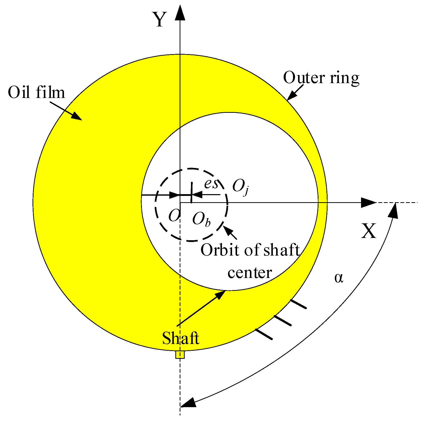
2.1. Numerical Modeling and Two-Phase Flow Theory

The SFD model considering oil supply is established. The outer ring of the SFD is equipped with oil supply holes, and the inner ring is equipped with semicircular arc oil supply grooves. The meshing and boundary conditions are set up for the SFD model. The meshing is shown in Figure 2. In order to ensure the mesh quality and geometry, local encryption of the oil film mesh is required, and mesh-independence validation is carried out. The final determination of the number of grid nodes is 144,434 and the number of grids is 133,538 [4]. The Reynolds number of the SFD is relatively small, so the flow state is set to laminar flow [31]. The boundary conditions are set as shown in Figure 3. The boundary conditions at the oil supply hole are “inlet”. The SFD inner and outer ring boundary conditions are “wall”, where the inner ring simulates a circular feed motion and the equation of motion is:
x = e sin Ω t + e s y = e cos Ω t
where e is the dynamic eccentricity, Ω is the precession angular velocity, and e s is the static eccentricity.
Due to the open structure at both ends of the open SFD, the two ends of the oil film were set as free open boundaries, considering air ingestion. The air volume fraction (AVF) is 0.99. Air ingestion refers to the fact that due to the pressure difference between the oil film pressure and the external ambient pressure, air is sucked into the damper along the area of the oil film that is lower than the ambient pressure and follows the oil film as it moves through the damper.
There is air ingestion in the open SFD, so the fluid domain is set up with a homogeneous mixture multiphase flow model. The mixture multiphase flow model is used to simulate the multiphase flow by solving the continuity and momentum equations in combination with the relative velocity equation, as well as the gas volume fraction equations, which have a high convergence rate. Where the continuity equation is:
t r α ρ α + r α ρ α U α = 0
r α is the volume fraction of each phase, r α = 1 is the sum of volume fractions, ρ α is the density of each phase, and U α is the velocity vector of each phase.
The homogeneous phase model is: U α = U, 1 ≤ α ≤ Np. The momentum equation is:
t ρ U + · ρ U · U μ U + U T = S M p
ρ = α = 1 N p r α ρ α , μ = α = 1 N p r α μ α , μ α is the dynamic viscosity of each phase, p is the pressure, and SM is the generalized momentum source term.
Due to the presence of air ingestion, the boundary condition setup requires additional mass coefficients, where the additional mass coefficients transmission equation is:
t ρ φ + · ρ U φ = · ρ D ϕ φ + S φ
The specific geometrical dimensions and oil parameters of the squeeze oil film damper used in the experiments and numerical simulations are listed in Table 1. The structural sketch is shown in Figure 4.

2.2. Experimental Study of Static Eccentric Squeeze Film Damper

In order to verify the correctness of the numerical simulation, a bidirectional excitation test rig was used. During the experiment, the equipment used mainly consisted of a signal generator, power amplifier, signal acquisition analyzer, bidirectional excitation tester, and oil looping system. Figure 5 shows the bidirectional excitation tester. The main test pieces used in the test process were the elastic support of the squirrel cage, flexible rods, and shafts. The squirrel cage’s spring support acts as a centering spring in the SFD, and its inner ring acts as the outer ring of the SFD. The shaker transmits a force to the outer ring of the squirrel cage through the flexible rod, which makes the squirrel cage mimic the shafts to perform rounding and is used to realize the squeezing effect on the oil film.
Figure 6 shows the connection of the test equipment. By regulating the signal generator to generate two simple harmonic signals with the same frequency and phase difference of 90°, and then sending the signals through the power amplifier to drive the shaker, which in turn stimulates the different feed speeds and amplitudes of the SFD, and then using the impedance head to obtain the excitation and response signals, and finally using the mechanical impedance method [16,31], the damping of the SFD in the non-supplied and supplied states was obtained, and the two were subtracted to obtain the oil film damping of the SFD.

2.3. Numerical Simulation Compared to Experiment

In order to verify the accuracy of the numerical simulation, the static eccentricity SFD experimental test was carried out with the help of a bidirectional excitation test rig, and the results of the experimental test were also compared with those of the numerical simulation for calculating the static eccentricity SFD. The static eccentricity given in the test and simulation is 0.02 mm. The comparison between the test results and the numerical simulation results is shown in Figure 7. As shown in the figure, the oil film damping shows a decreasing trend with increasing frequency, and the maximum error between the test results and the numerical simulation results is 12.5%. Due to the fact that the position of the static eccentricity in the test cannot be completely determined, and there is a certain degree of error in the process of assembly, the higher the frequency, the worse the stability, resulting in a larger relative error.

3. Numerical Simulation Studies

In the actual aero-engine, the initial position of static eccentricity and the size of static eccentricity are not completely determined. Therefore, the effects of different static eccentric distances and static eccentric positions on the air ingestion distribution and the damping properties of the SFD were investigated.

3.1. Effect of the Angle between the Static Eccentricity Direction and the Circumferential Direction of the Oil Supply Hole on the Squeeze Film Damper

In order to investigate the effect of the angle between the static eccentricity direction and the circumferential direction of the oil supply hole on the vibration damping properties of the SFD, the angle α between the static eccentricity direction and the circumferential direction of the oil supply hole conducts numerically simulated in the range of 0° to 180°. The static eccentricity direction and the circumferential angle of the oil supply hole are shown in Figure 8.
Figure 9 and Figure 10 show the air ingestion in the oil film of the SFD. As shown in the figures, the air ingestion area in the oil film mainly exists at both ends of the oil film. As the angle between the static eccentric direction and the circumferential direction of the oil supply hole increases, the air ingestion area at both ends of the oil film gradually expands. The larger the static eccentricity distance, the greater the effect of the angle between the static eccentricity direction and the circumferential direction of the oil supply hole on the air ingestion area at both ends of the oil film. As shown in Figure 9a–d, when the static eccentricity distance is 0.01 mm, with the increase of the angle between the static eccentricity direction and the circumferential direction of the oil supply hole, the change in the air ingestion area in the oil film is not significant. However, when the static eccentricity distance increases to 0.03 mm, as shown in Figure 10a–d, with the increase of the angle between the static eccentricity direction and the circumferential direction of the oil supply hole, the air ingestion area in the oil film significantly increases.
The results of oil film damping at different circumferential angles between the static eccentricity direction and the oil supply hole are shown in Figure 11. As shown in the figure, the circumferential angle increases, the oil film damping gradually decreases, and as the static eccentricity increases, the oil film damping obviously decreases. This is because as the circumferential angle increases, the static eccentricity distance becomes bigger, and the impact of the circumferential angle on the air ingestion area at both ends of the oil film is bigger, leading to more severe damage to the integrity of the oil film and a decrease in oil film damping. According to Figure 11, when the circumferential angle is small, the oil film damping increases with the increase of the static eccentricity distance; when the circumferential angle is large, the oil film damping decreases with the increase of the static eccentricity distance. As shown in Figure 11a–c, to the left of the intersection point A, the oil film damping increases with the increase of static eccentricity; to the right of the intersection point A, the oil film damping decreases with the increase of static eccentricity. The intersection point A gradually moves to the right as the dynamic eccentricity increases.

3.2. Effect of Static Eccentricity on Squeeze Film Dampers

Through the study of the effect of the circumferential angle on the SFD in Section 3.1, the static eccentricity distance has different influences on the oil film damping at different circumferential angles. Therefore, in this section, different circumferential angles are selected to be analyzed in the numerical simulation of the SFD at different static eccentricity distances. Changing the es value in the equation of motion (1) in Section 2.1 achieves the static eccentricity distance change.
Firstly, as an example, a dynamic eccentricity of 0.014 mm and a circumferential angle of 90° are selected. Figure 12 and Figure 13 show the influence of different static eccentricity distances on the distribution of oil film pressure. As shown in the figures, without considering the pressure at the oil supply hole, due to the influence of static eccentricity distance, the maximum pressure of the oil film significantly decreases when it moves from 0T to 2/4T. With the increase of static eccentricity distance, when the oil film is at 0T, the maximum pressure and the minimum pressure of the oil film become bigger at the same time, and when the oil film is at 2/4T, the maximum pressure of the oil film and the minimum pressure of the oil film become smaller.
Secondly, the 2/4T moment is another example. Figure 14 and Figure 15 show the effect of static eccentricity distance on the air distribution in the SFD. As shown in the figures, with the increase of static eccentricity distance, the air ingestion area gradually expands, and the phenomenon of expanding the air ingestion area mainly occurs in the +X-axis. When the static eccentricity distance is large, the air ingestion area in the −X-axis direction also increases. As shown in Figure 16 (air ingestion distribution at different oil supply flow rates), the phenomenon that the air ingestion area becomes larger in the oil film −X-axis direction significantly decreases when the oil supply flow increases. According to Figure 16 and Figure 17 (oil flow diagram), when the static eccentricity distance is large, the oil film in the −X-axis direction is thick, while the oil film in the +X-axis direction is thin. When the oil passes through the +X-axis in the movement process, the oil quickly extrudes out of the oil film. When the oil flows to the −X-axis, the oil cannot be replenished in time, resulting in a larger air ingestion area at both ends of the −X-axis oil film. Compared to Figure 14 and Figure 15, the static eccentricity distance has a greater effect on the air ingestion area as the circumferential pinch angle becomes larger.
The oil film damping at different static eccentricity distances is obtained by numerical simulation, as shown in Figure 18. As shown in the figure, when the circumferential angle is 30°, the oil film damping increases with the increase of the static eccentricity distance. Because the static eccentricity distance increases, the relative dynamic eccentricity increases (the relative dynamic eccentricity consists of the static eccentricity and the absolute dynamic eccentricity together [3]), which leads to increases in the oil film damping. When the circumferential angle is 60°, and the static eccentricity distance is 0.01–0.03 mm, the oil film damping does not change much. However, as the static eccentricity distance continues to increase, the oil film damping increases when the frequency is low. When the frequency is high, the oil film damping first decreases and then increases. When the circumferential angle is 90°, the oil film damping first decreases and then increases with the increase of static eccentricity distance, mainly due to the increase in static eccentricity distance with a smaller static eccentric distance, resulting in the air ingestion of the distribution range becoming larger, destroying the integrity of the oil film. As a result, the oil film damping decreases with the increase of static eccentricity distance. When the static eccentricity distance is large, the relative dynamic eccentricity increases with the increase of static eccentricity, leading to increased oil film damping.

3.3. Effect of Dynamic Eccentricity on Static Eccentric Squeeze Film Dampers

In order to study the effect of the dynamic eccentricity on the static eccentricity SFD, the SFD model was numerically simulated with the dynamic eccentricity in the range of 0.014–0.07 mm to obtain the effect of different dynamic eccentricities on the static eccentricity SFD.
Through numerical simulation with a circumferential angle of 90° and a static eccentricity of 0.02 mm, as shown in Figure 19, the air distribution and air volume fraction in the oil film at 2/4T with different dynamic eccentricities. As shown in the figure, with the increase of the dynamic eccentricity, the air ingestion area increases gradually and mainly appears in the +X-axis direction. As the differential pressure of the oil film increases with the increase of the dynamic eccentricity, the negative pressure area of the oil film becomes larger, the maximum negative pressure of the oil film becomes smaller, and under the action of the differential pressure, the volume fraction of the air ingestion becomes larger, and the air ingestion area at both ends of the oil film increases.
The influence of different dynamic eccentricities on the static eccentricity of SFD oil film damping was calculated through numerical simulation, as shown in Figure 20. As shown in the figure, the oil film damping decreases and then increases with the increase of the dynamic eccentricity. As the dynamic eccentricity increases, the volume fraction of air ingestion in the oil film increases, the air ingestion areas become larger, and the effective area of the oil film significantly decreases, resulting in a decrease in oil film damping. At the same time, when the static eccentricity distance increases, the oil film damping decreases less significantly with the increase of the dynamic eccentricity; when the dynamic eccentricity continues to increase, the rise of the oil film damping becomes obvious.

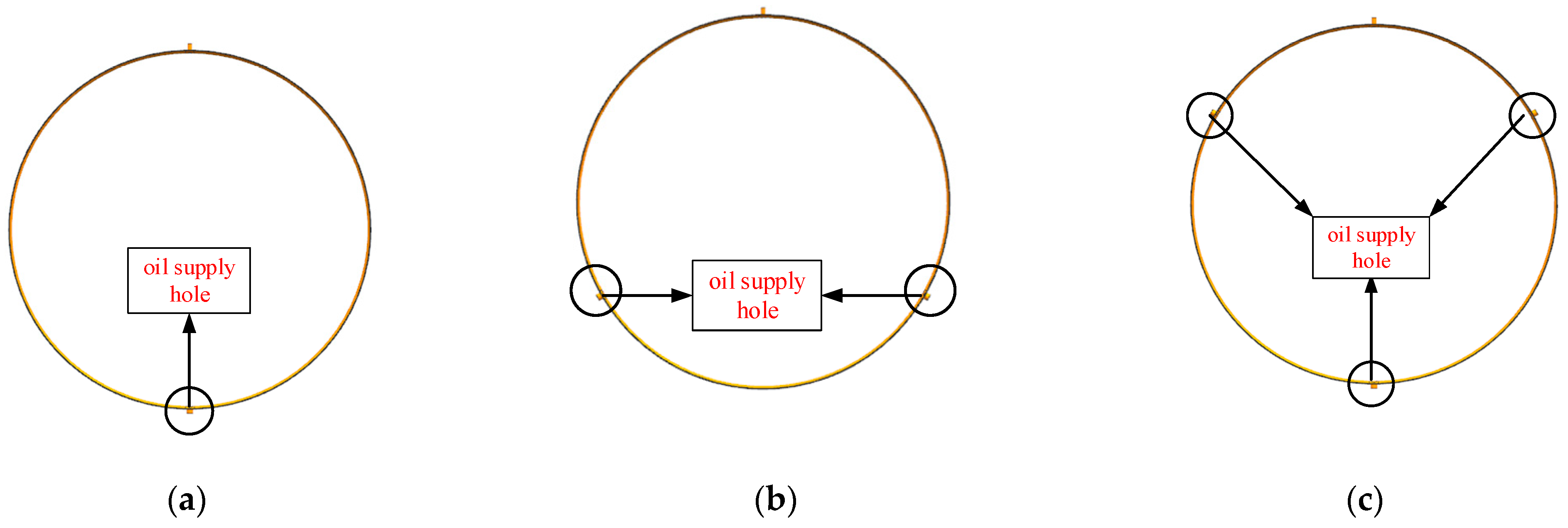
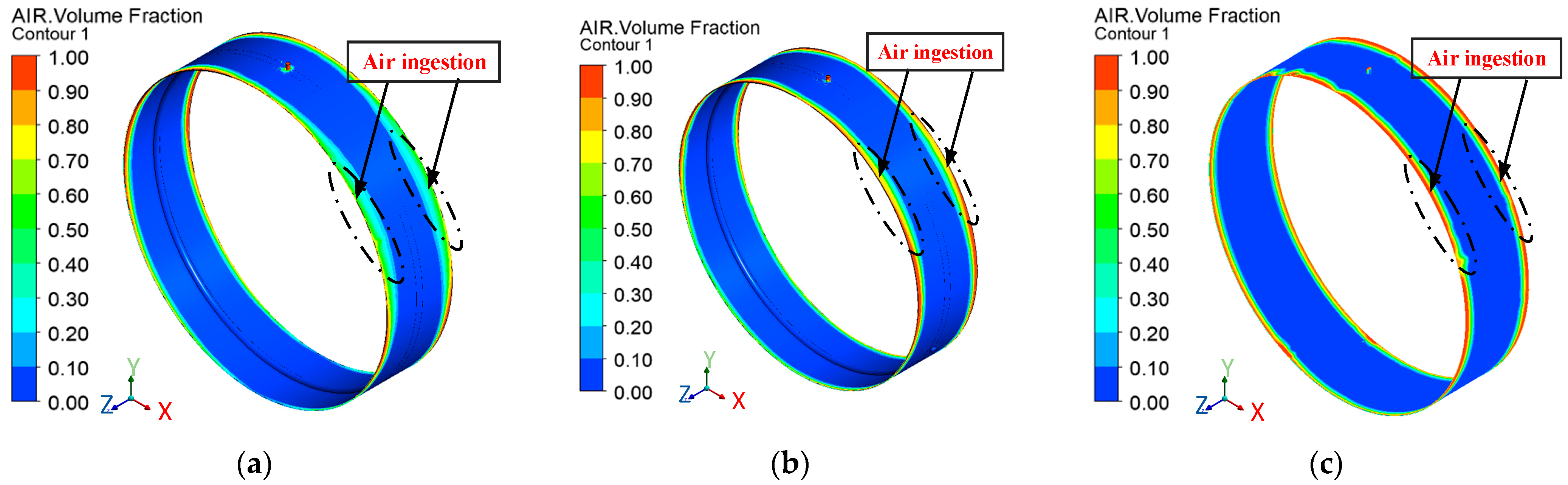
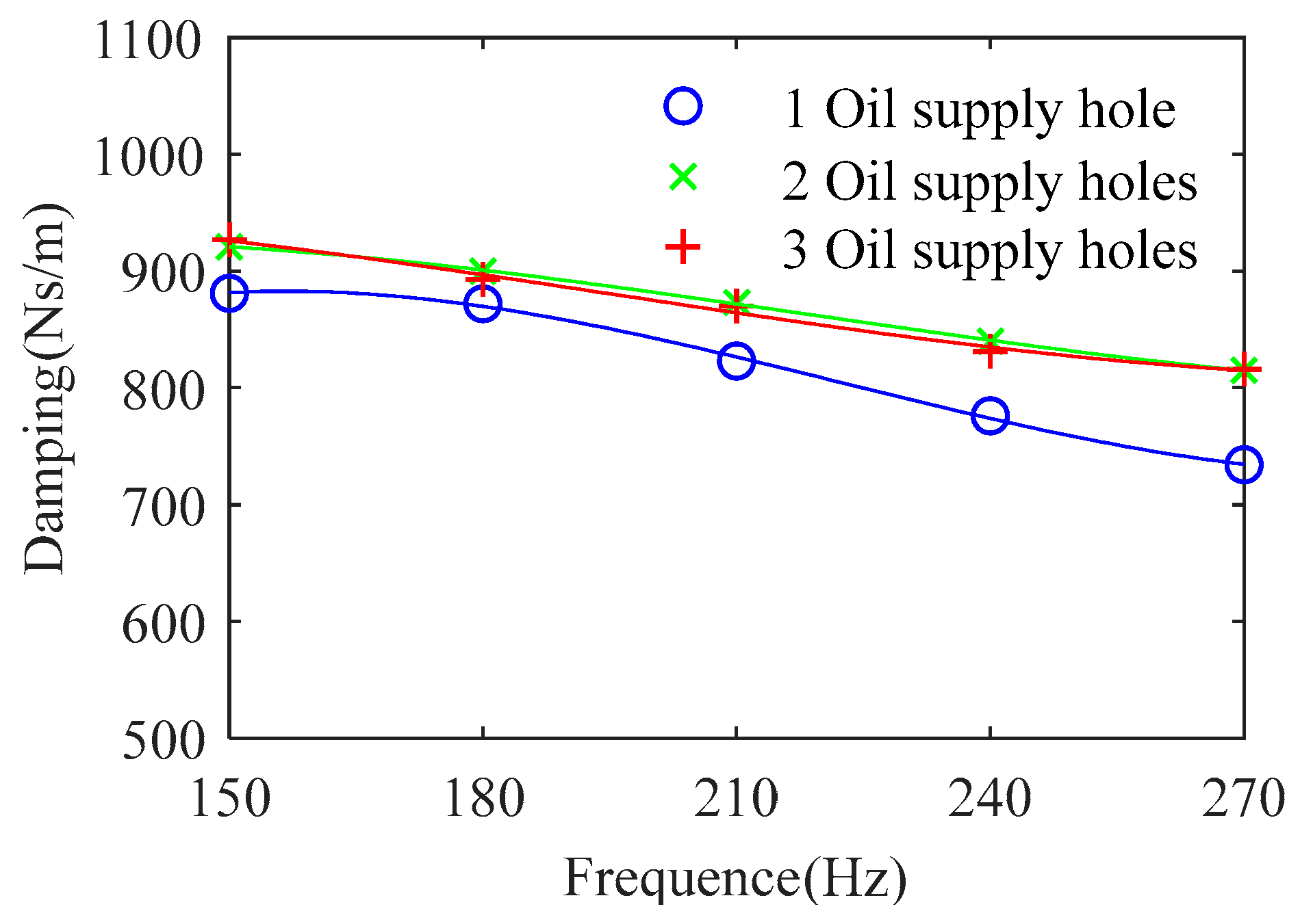
3.4. Effect of the Number of Oil Supply Holes on Static Eccentric Squeeze Film Dampers

Different numbers of oil supply holes affect differently the SFD. In order to study the effect of the number of oil supply holes on the static eccentric SFD, the results of modeling the SFD with different numbers of oil supply holes is shown in Figure 21.
Through the numerical simulation of the static eccentricity SFD with different numbers of oil supply holes, taking a static eccentricity of 0.02 mm as an example, the air ingestion distribution is obtained at 2/4T with different numbers of oil supply holes, as shown in Figure 22. As shown in the figure, the air ingestion area at both ends of the SFD is significantly larger in 1 oil supply hole than in 2 oil supply holes or 3 oil supply holes, and the distribution of circumferential air ingestion is more inhomogeneous in the case of 1 oil supply hole.
Through the numerical simulation calculation of different oil supply holes, the oil film damping changes rule, as shown in Figure 23. As shown in the figure, the oil film damping of 1 hole is smaller than the oil film damping of 2 holes or 3 holes. In 2 holes and 3 holes, the size of the oil film damping is relatively similar. Since the air ingestion area by the SFD with 1 hole is significantly larger than with 2 holes or 3 holes, the oil film damping with 1 hole is obviously smaller than with 2 holes or 3 holes.

4. Conclusions

In order to study the effect of static eccentricity on the vibration damping properties of SFD, numerical simulation is utilized for the present study and verified by bidirectional excitation test. The conclusions are as follows:
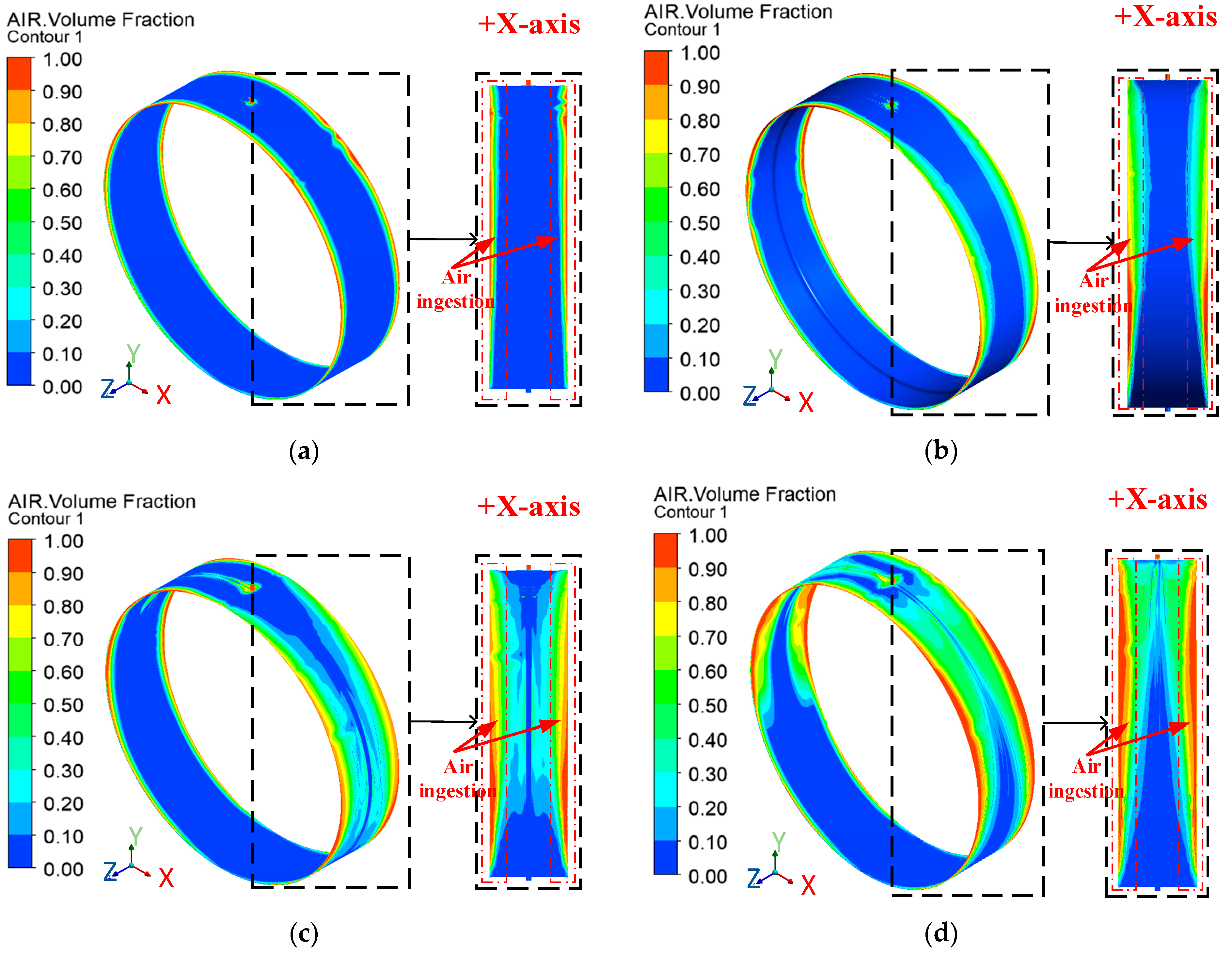
  • As the static eccentricity direction and the oil supply hole circumferential angle become larger, the air ingestion area gradually expands, and the oil film damping gradually decreases. The larger the static eccentricity distance, the greater the effect of the circumferential angle on the air ingestion area, and the more obvious the decrease in oil film damping. When the circumferential angle is 180°, the oil film damping is the smallest and the air intake area is the largest.
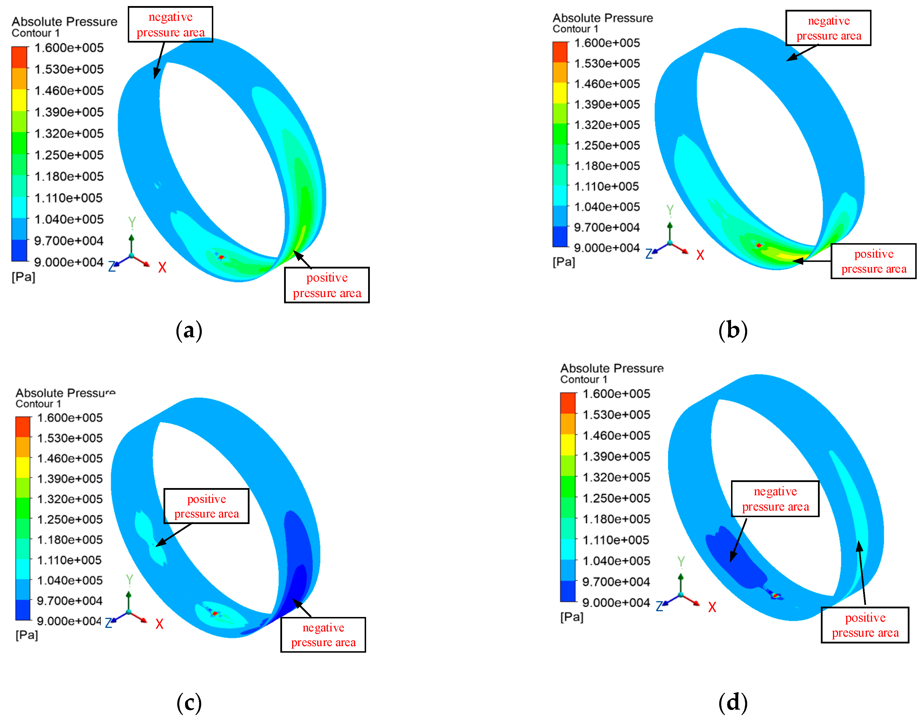
  • As the static eccentricity distance increases, when the oil film is at 0T, the maximum and minimum pressure of the oil film increase simultaneously. When the oil film is at 2/4T, the maximum and minimum pressure of the oil film decrease. When the oil film moves from 0T to 2/4T, the maximum pressure of the oil film significantly decreases. As the static eccentricity distance increases, the air ingestion area gradually expands, and the expansion of the air ingestion area occurs mainly in the static eccentricity direction (+X-axis direction). When the circumferential angle is small, the oil film damping increases with the increase of static eccentricity. When the circumferential angle is large, the oil film damping first decreases and then increases. The larger the circumferential angle, the smaller the minimum value of oil film damping, which gradually moves towards the direction of larger static eccentricity.
  • As the dynamic eccentricity increases, the air ingestion area gradually increases and occurs mainly in the static eccentricity direction (+X-axis direction). As the dynamic eccentricity increases, the oil film damping first decreases and then increases.
  • The air ingestion area at both ends of the SFD is significantly larger in 1 oil supply hole than in 2 oil supply holes or 3 oil supply holes. The distribution of circumferential air ingestion is less uniform with 1 oil supply hole. The oil film damping of 1 oil supply hole is smaller than the oil film damping of 2 oil supply holes or 3 oil supply holes. The oil film damping of the 2 and 3 oil supply holes is about 5% higher than that of the 1 oil supply hole.
  • It is known from the present study that the static eccentricity and circumferential angle have a great influence on the oil film damping and air ingestion area. When the static eccentricity and the circumferential angle increase, the air ingestion area increases, so in the actual installation of the SFD, to consider the static eccentricity and the circumferential angle on the SFD, when the circumferential angle is less than 60°, you can appropriately increase the static eccentricity. When the circumferential angle is greater than 60°, the static eccentricity can be appropriately reduced. This study provides some theoretical support and supplementation to the experimental research on the application of aero-engines, which cannot determine the static eccentricity situation completely and accurately.

Author Contributions

Conceptualization, H.Z.; methodology, H.Z.; software, L.F.; validation, L.F.; formal analysis, L.F.; investigation, L.F.; resources, M.Z.; data curation, L.F. and M.Z.; writing—original draft preparation, L.F.; writing—review and editing, J.S. and G.C.; visualization, H.Z. and J.S.; supervision, H.Z.; project administration, H.Z.; funding acquisition, H.Z. All authors have read and agreed to the published version of the manuscript.

Funding

This research was funded by the National Natural Science Foundation of China (grant number 52175106), Plan for Young and Middle-Aged Innovators of Shenyang (grant number RC220326) and Liaoning Revitalization Talents Program (grant number XLYC2203146).

Data Availability Statement

Data are contained within the article.

Conflicts of Interest

Ming Zhang was employed by the company AECC South Industry Company Limited. The remaining authors declare that the research was conducted in the absence of any commercial or financial relationships that could be construed as a potential conflict of interest.

References

  1. Rodríguez, B.; San Andrés, L. Dynamic Forced Performance of an O-Rings Sealed Squeeze Film Damper Lubricated with a Low Supply Pressure and a Simple Method to Quantify Air Ingestion. In ASME Turbo Expo 2023: Turbomachinery Technical Conference and Exposition 2023, Boston, Massachusetts, USA, 26–30 June 2023, Volume 11A: Structures and Dynamics—Aerodynamics Excitation and Damping; Bearing and Seal Dynamics: New York, NY, USA, 2023. [Google Scholar]
  2. Zhao, X.W. An Investigation on the Dynamic Characteristics of Extruded Oil Film Damper under Static Eccentricity; Nanjing University of Aeronautics and Astronautics: Nanjing, China, 2019. [Google Scholar]
  3. Xu, W.W.; Zhang, D.H.; Wang, P. Influence of the static eccentricity of rotor extruded oil film damper on vibration damping effect. Vib. Shock 2021, 40, 55–61. [Google Scholar]
  4. Zhou, H.L.; Chen, X.; Zhang, M. Numerical Investigation on Periodically Time-Varying Dynamic Characteristics of Static Eccentric Squeeze Film Damper. J. Appl. Fluid Mech. 2021, 14, 389–399. [Google Scholar]
  5. Li, Y.; Liao, M.F.; Wang, S.J. Influence of concentricity and friction of extruded oil film dampers on rotor vibration characteristics. Vib. Shock 2020, 39, 150–156+174. [Google Scholar]
  6. Feng, Y.; Deng, W.Q.; Liu, W.K. Comparative experimental study on damping characteristics of concentric and non-concentric extruded oil film dampers. Mech. Sci. Technol. 2023, 42, 978–984. [Google Scholar]
  7. Cui, Y.; Li, T.; Jiang, Q.; Wang, Y.L. Numerical simulation of cavitation flow field characteristics of non-concentric extruded oil film damper. J. Harbin Eng. Univ. 2020, 41, 978–984. [Google Scholar]
  8. Lu, Y.; Tang, Z.H.; Cheng, X.M. Characterization and experimental verification of the response of a high-speed flexible rotor-uncentered SFD system. Vib. Shock 2023, 42, 114–119+193. [Google Scholar]
  9. Liu, Z.C.; Liao, M.F.; Cong, P.H. Experimental study on the effect of static eccentricity on the damping characteristics of extruded oil film dampers. Propuls. Technol. 2016, 37, 1560–1568. [Google Scholar]
  10. San Andrés, L.; Den, S.; Jeung, S.H. On the Force Coefficients of a Flooded, Open Ends Short Length Squeeze Film Damper: From Theory to Practice (and Back). J. Eng. Gas Turbines Power 2018, 140, 012502. [Google Scholar] [CrossRef]
  11. Fan, T.; Behdinan, K. Evaluation of Linear Complementarity Problem Method in Modeling the Fluid Cavitation for Squeeze Film Damper with off-Centered Whirling Motion. Lubricants 2017, 5, 46. [Google Scholar] [CrossRef]
  12. San Andrés, L.; Seshagiri, S. Damping and Inertia Coefficients for Two End Sealed Squeeze Film Dampers With a Central Groove: Measurements and Predictions. J. Eng. Gas Turbines Power 2013, 135, 112503. [Google Scholar] [CrossRef]
  13. Jeung, S.H.; San Andrés, L.; Bradley, G. Forced Coefficients for a Short Length, Open Ends Squeeze Film Damper With End Grooves: Experiments and Predictions. J. Eng. Gas Turbines Power 2016, 138, 022501. [Google Scholar] [CrossRef]
  14. San Andrés, L. Force coefficients for a large clearance open ends squeeze film damper with a central feed groove: Experiments and predictions. Tribol. Int. 2014, 71, 17–25. [Google Scholar] [CrossRef]
  15. San Andrés, L.; Jeung, S.H. Experimental Performance of an Open Ends, Centrally Grooved, Squeeze Film Damper Operating With Large Amplitude Orbital Motions. J. Eng. Gas Turbines Power 2015, 137, 032508. [Google Scholar] [CrossRef]
  16. San Andrés, L.; Den, S.; Jeung, S.H. Transient Response of a Short-Length (L/D = 0.2) Open-Ends Elastically Supported Squeeze Film Damper: Centered and Largely off-Centered Whirl Motions. J. Eng. Gas Turbines Power 2016, 138, 122503. [Google Scholar] [CrossRef]
  17. Chen, X.; Gan, X.; Ren, G. Dynamic modeling and nonlinear analysis of a rotor system supported by squeeze film damper with variable static eccentricity under aircraft turning maneuver. J. Sound Vib. 2020, 485, 115551. [Google Scholar] [CrossRef]
  18. Chen, X.; Gan, X.; Jiang, S. Dynamic Characteristics of a Squeeze Film Damped Rotor System Considering Instantaneous Static Eccentricity in Maneuvering Flight. In Proceedings of the ASME Turbo Expo 2020: Turbomachinery Technical Conference and Exposition 2020, Virtual, 21–25 September 2020; Volume 10B: Structures and Dynamics, pp. 1–16. [Google Scholar]
  19. Lu, X.; San Andrés, L.; Koo, B. On the Effect of the Gap of End Seals on Force Coefficients of a Test Integral Squeeze Film Damper: Experiments and Predictions. J. Eng. Gas Turbines Power 2021, 143, 011014. [Google Scholar] [CrossRef]
  20. Chen, Y.L.; Ma, H.F.; Huang, Y.Z. Experimental study on cavitation effect of extruded oil film damper under low oil supply pressure. J. Aerosp. Dyn. 2023, 39, 20220061. [Google Scholar]
  21. Zhang, W.; Wang, H.J.; Ding, Q. Characterization of oil film parameters of a two-phase flow extruded oil film damper at very low pressure. J. Aerosp. Dyn. 2020, 35, 560–568. [Google Scholar]
  22. Zhang, Y.S. Study of Cavitation Effect in Extruded Oil Film Dampers; Shanghai University of Applied Sciences: Shanghai, China, 2023. [Google Scholar]
  23. Zhang, W.; Ding, Q. Experimental study of air-cavity flow pattern and vibration damping characteristics of an extruded oil-film damper during fuel breakup. Exp. Mech. 2020, 35, 688–694. [Google Scholar]
  24. Cui, Y.; Luo, J.D.; Qiu, K. Flow field and damping characteristics of flap seal extruded oil film damper. J. Aerosp. Dyn. 2021, 36, 2474–2481. [Google Scholar]
  25. Shen, C.; Feng, C.J.; Luo, G.H. Dynamic characterization of a floating-ring extruded oil film damper considering cavitation effect. In Proceedings of the 14th National Conference on Vibration Theory and Applications 2021, Tianjin, China, 14–16 August 2021. [Google Scholar]
  26. Wang, Q.Z.; Cui, Y.; Wu, Z. Comparison of cavitation flow field characteristics of extruded oil-film damper under three cavitation models. J. Dalian Marit. Univ. 2020, 46, 124–130. [Google Scholar]
  27. Zhou, H.L.; Cao, G.Y.; Chen, X. A Study on the Thermal Properties of Oil-Film Viscosity in Squeeze Film Dampers. Lubricants 2023, 11, 163. [Google Scholar] [CrossRef]
  28. Tang, Z.H.; Chen, X.; Zhou, H.L. Dynamic characteristics of open-ends squeeze film dampers with air ingestion. Int. J. Turbo Jet-Engines 2023. [Google Scholar] [CrossRef]
  29. Li, T. Study on Cavitation Flow Field Characteristics and Damping Coefficient of Squeeze Film Dampers; Dalian Maritime University: Dalian, China, 2020. [Google Scholar]
  30. Chen, Y.L.; Ma, H.F.; Huang, Y.Z. Experiments on the effect of end seal opening angle on squeeze film dampers. J. Aerosp. Dyn. 2023, 38, 1–10. [Google Scholar]
  31. Zhou, H.L.; Chen, X.; Zhang, Y.Q.; Ai, Y.T.; Sun, D. An analysis on the influence of air ingestion on vibration damping properties of squeeze film dampers. Tribol. Int. 2020, 145, 106168. [Google Scholar] [CrossRef]
Figure 1. Static eccentric SFD working state structure schematic diagram.
Lubricants 12 00075 g001
Figure 2. Messing.
Figure 2. Messing.
Lubricants 12 00075 g002
Figure 3. Boundary condition setting.
Lubricants 12 00075 g003
Figure 4. Sketch of squeeze film damper structure.
Lubricants 12 00075 g004
Figure 5. Bidirectional excitation tester: (a) Physical drawing of the bidirectional excitation tester; (b) Schematic diagram of the structure of the bidirectional excitation tester.
Lubricants 12 00075 g005
Figure 6. Connection diagram of test equipment.
Lubricants 12 00075 g006
Figure 7. Comparison of numerical simulation and experimental test.
Lubricants 12 00075 g007
Figure 8. Schematic diagram of the static eccentricity direction and the circumferential angle of the oil supply hole.
Lubricants 12 00075 g008
Figure 9. Effect of static eccentricity direction and circumferential angle of oil supply hole for static eccentricity distance of 0.01 mm: (a) Circumferential angle 30°; (b) Circumferential angle 60°; (c) Circumferential angle 90°; (d) Circumferential angle of 150°.
Lubricants 12 00075 g009
Figure 10. Effect of static eccentricity direction and circumferential angle of oil supply hole for static eccentricity distance of 0.03 mm: (a) Circumferential angle 30°; (b) Circumferential angle 60°; (c) Circumferential angle 90°; (d) Circumferential angle of 150°.
Lubricants 12 00075 g010
Figure 11. Effect of the angle between static eccentricity direction and oil supply hole circumference on oil film damping: (a) Dynamic eccentricity 0.014 mm; (b) Dynamic eccentricity 0.049 mm; (c) Dynamic eccentricity 0.07 mm.
Lubricants 12 00075 g011
Figure 12. Cloud diagram of oil film pressure distribution at different moments when static eccentricity distance is 0.03 mm: (a) 0T; (b) 1/4T; (c) 2/4T; (d) 3/4T.
Lubricants 12 00075 g012
Figure 13. Cloud diagram of oil film pressure distribution at different moments with static eccentricity distance of 0.07 mm: (a) 0T; (b) 1/4T; (c) 2/4T; (d) 3/4T.
Lubricants 12 00075 g013
Figure 14. Effect of static eccentricity on air ingestion distribution at a circumferential angle of 30°: (a) Static eccentricity 0.01 mm; (b) Static eccentricity 0.03 mm; (c) Static eccentricity 0.05 mm; (d) Static eccentricity 0.07 mm.
Lubricants 12 00075 g014
Figure 15. Effect of static eccentricity on air ingestion distribution at a circumferential angle of 90°: (a) Static eccentricity 0.01 mm; (b) Static eccentricity 0.03 mm; (c) Static eccentricity 0.05 mm; (d) Static eccentricity 0.07 mm.
Lubricants 12 00075 g015
Figure 16. Air ingestion distribution at a static eccentricity of 0.07 mm and different oil supply flow rates: (a) Oil supply flow rate 1.3 L/min; (b) Oil supply flow rate 2.6 L/min.
Lubricants 12 00075 g016
Figure 17. Slippery oil flow diagram.
Lubricants 12 00075 g017
Figure 18. Effect of static eccentricity on oil film damping: (a) Circumferential angle 30°; (b) Circumferential angle 60°; (c) Circumferential angle 90°.
Lubricants 12 00075 g018
Figure 19. Air ingestion distribution in the oil film for different dynamic eccentricities: (a) Dynamic eccentricity 0.014 mm; (b) Dynamic eccentricity 0.042 mm; (c) Dynamic eccentricity 0.07 mm.
Lubricants 12 00075 g019
Figure 20. Effect of different dynamic eccentricity on oil film damping.
Lubricants 12 00075 g020
Figure 21. Modeling the number of different oil supply holes: (a) 1 oil supply hole; (b) 2 oil supply holes; (c) 3 oil supply holes.
Lubricants 12 00075 g021
Figure 22. Air ingestion distribution cloud with different number of oil supply holes at 210 Hz: (a) 1 oil supply hole; (b) 2 oil supply holes; (c) 3 oil supply holes.
Lubricants 12 00075 g022
Figure 23. Effect of number of oil supply holes on oil film damping.
Lubricants 12 00075 g023
Table 1. Oil film geometry and oil parameter.
NameSymbolValueDimension
Shaft diameterD80.84mm
ClearanceC0.14mm
Axial lengthL20mm
Hole diameterD1.5mm
Oil viscosity 0.003pa·s
Densities Ρ 800 kg / m 3
Oil supply flow 1.3L/min
Disclaimer/Publisher’s Note: The statements, opinions and data contained in all publications are solely those of the individual author(s) and contributor(s) and not of MDPI and/or the editor(s). MDPI and/or the editor(s) disclaim responsibility for any injury to people or property resulting from any ideas, methods, instructions or products referred to in the content.

