Article

Experimental and Numerical Analysis of Torsional—Lateral Vibrations in Drive Lines Supported by Hydrodynamic Journal Bearings

by
Fabrizio Antonio Stefani
*,
Carlo Alberto Niccolini Marmont Du Haut Champ
,
Paolo Silvestri
and
Aristide Fausto Massardo
Department of Mechanical, Energy, Management and Transportation Engineering (DIME), Polytechnic School, University of Genoa, 16145 Genoa, Italy
*
Author to whom correspondence should be addressed.
Lubricants 2024, 12(3), 82; https://doi.org/10.3390/lubricants12030082
Submission received: 26 January 2024 / Revised: 28 February 2024 / Accepted: 1 March 2024 / Published: 6 March 2024
(This article belongs to the Special Issue Applied Tribology: Rotordynamics)

Abstract

:
The driving and resistance torques of some rotating machinery for industrial applications are nonstationary and affect system dynamics. Under such operating conditions, coupling between torsional and lateral vibrations may become significant for drive lines supported by hydrodynamic bearings in particular design configurations. Indeed, the occurrence of fluid–structure interactions causes a reduction in the stability threshold of the journal bearings. A hypothesis based on Hopf bifurcation theory (HBT), which justifies how the coupling phenomenon develops, is validated by means of overall experimental observations and a suitable numerical model. When the pulsating driving torque induces significant angular speed oscillation, the rotor-bearing system lateral operating response becomes more complex, and bearing instability onset is detected. Such observation proves the influence of bearings in converting torsional oscillations to lateral vibrations. Particularly, during run-up and run-down tests, localized hysteresis is observed in trends of fundamental order contents. The numerical model of the hydrodynamic bearings solves the Reynolds equation in unsteady conditions to quantify the lateral vibrations amplitude in the presence of both angular speed oscillation and dynamic perturbation. The proposed approach proves the onset of torsional–lateral vibration coupling due to hydrodynamic bearings, to a certain extent. The detected hysteresis phenomena can also be explained by the onset of journal bearing instability.

Graphical Abstract

1. Introduction

The distinct behavior of rotordynamic components may strongly affect the performance of a mechanical system and, more specifically, of a rotor-bearing assembly. As a consequence, the dynamic response of the machine may become more complex and less predictable by means of theoretical and numerical classical models, as in the case of rotors supported by aerodynamic bearings [1,2].
The study of the dynamics of rotor-bearing systems with reference to their stability and torsional–lateral vibration coupling has been the subject of extensive research [3] and still requires work.

1.1. Nature of the Issue

Hydrodynamic journal bearings play a significant role in determining the stability threshold of real-size rotors when they are forced to work far from their on-design conditions [4]. Indeed, in specific industrial application cases, some irregular external or internal loads, capable of influencing the rotational speed and not properly considered in journal bearing preliminary design, may modify the dynamic stability threshold of such hydrodynamic supports. For instance, an unsteady component in the driving torque or variable reduced inertia that causes a significant torsional response may modify journal bearing vibrational behavior and might even lead to a coupling between shaft line torsional and lateral vibrations. In such cases, the detected system response may become anomalous, with experimental evidence of hysteresis and jump-up between run-up and run-down curves. The subsequent investigation becomes very complex, as it is not trivial to identify and isolate the causes of such unexpected behavior. Similar instability phenomena are deeply investigated in the present work by analyzing the numerical response of a sample drive line in comparison with overall experimental results. Indeed, their practical implication may become very influential. For example, when vibration amplitudes’ overall values must be optimized, the above-mentioned behavior makes it very challenging to improve system dynamics.
When investigating the dynamical behavior of complex mechanical systems involving several degrees of freedom, under given external conditions, the operational response can also be ascribable to coupling phenomena. Their entity may vary in a significant way, causing more or less marked cross-coupled behavior. In some cases, such operating response might even be related to hysteresis phenomena, which cannot be simulated by means of classic linear models. A typical example is represented by specific rotating machinery applications, whose response is not easily interpretable by means of standard aprioristic knowledge, as shaft torsional and lateral dynamics are not completely independent. In the most recurring case, as reported in [5,6], the rotor torsional response is influenced by lateral vibrations. Indeed, the technical literature concerning this topic can be divided into two main classes, where the first category includes works investigating the influence of lateral vibrations on the torsional response. Particularly, some papers ([7,8]) present examples where such coupling is due to the presence of gearboxes or complex devices like multi-disk mechanical systems. Furthermore, in the case of weakly damped rotor systems, a related instability onset may influence the machine functioning [9]. Lateral vibrations also affect the torsional response in other cases [10,11,12], where the cause is identified in the mechanical unbalance, which makes up the main external force acting on the system. In [11], such experimental evidence is also confirmed by resorting to finite element (FE) models.
In the literature of the second category, more related to the present work, the coupling mechanism direction is different in that the energy is transferred from torsional to lateral vibrations. The first example is reported in [13], where the torsional–lateral vibration coupling is due to the presence of an interposed gearbox. Differently, in [14,15], it is due to rubbing between the rotor and frame caused by a cracked shaft and rotor anisotropy, respectively.
If strong non-linearities occur, the onset of a hysteresis loop due to the coupled lateral and torsional response leads to a different relationship between run-up and run-down curves [16]. The coupled torsional–lateral dynamics have also been studied both analytically and experimentally in [17], where the case of a motor pump assembly is considered.
Reference [18] investigates both numerically and experimentally (by means of a custom-designed prototype) the interaction between lateral and torsional vibrations caused by mass unbalance. It may be due to system intrinsic coupling between lateral and torsional structural dynamics or discontinuous friction torque. Furthermore, the paper proves that an increase in the mechanical imbalance can lead to a stabilization of the torsional response, thus making the friction-induced limit cycle disappear. The authors of [19] have performed a numerical investigation about the vibrational response in a gear-rotor-bearings system, where the influence of gear eccentricity fluctuations on coupled torsional–lateral behavior is considered by varying the gear mesh stiffness in the assessment of the dynamic system response.
The work [20] deals with the effects of geometrical non-linearity due to large rotor overhang, which modifies the operating mode shapes causing the onset of a hysteresis cycle between run-up and run-down curves. Paper [21] deals with the numerical identification of the instability threshold speed in two different hydrodynamic journal bearings test bench arrangements. In the former, the onset of instability occurs at the characteristic oil-whip frequency, while in the latter, unstable conditions arise at a lower speed. Such an example proves that, since the oil-whip phenomenon is the only fluid-induced instability usually considered in the design phase, there is experimental evidence that stability thresholds are not correctly predicted by design calculations. In this regard, a deeper understanding of the instability mechanisms affecting hydrodynamic journal bearings is required.
Reference [22] investigates both analytically and numerically coupling phenomena due to hydrodynamic and gyroscopic effects in rotors supported by plain (cylindrical) and tilting-pad bearings. Indeed, although hydrodynamic journal bearings introduce high damping in the rotor-bearing system, they also involve the cross coupling of rotor translational motions, which is one of the main sources of oil-induced instability. The inherent nonlinearity of hydrodynamic journal bearings turns out to be significant for relative eccentricities larger than 0.6. Indeed, in such working conditions, most existing linear models cannot reliably predict the journal trajectory. Such strong nonlinearities involving cross coupling behavior are the main sources of the complex dynamic phenomena encountered in rotor-bearing systems.
Other studies are specifically aimed at determining the rotordynamic stability range and, particularly, the threshold values of the speed or external perturbation amplitude. For instance, the authors of [23,24] have assessed the stability threshold of rotor-bearing systems. In addition, they have experimentally observed a hysteresis cycle, which has been accurately simulated by a numerical method based on Hopf bifurcation theory (HBT). The authors of [25] have numerically studied the effect of damping on the hydrodynamic bearings of an actual industrial rotor-bearing system (i.e., steam turbine). In [26], the effect of rotor flexibility is added to the same numerical model proposed in [23,24] to assess how it affects the rotordynamic system stability. Again, in [27], such numerical approach is applied to the particular case of floating ring bearings, which allow, in equivalent operating conditions, a wider rotordynamic stability range in comparison with conventional journal bearings.
Finally, reference [28] presents an insight into the influence of radial clearance on journal bearing stability. It shows that increasing the clearance enlarges the rotordynamic system stability threshold, all other conditions being equal.

1.2. Aim of the Work

The goal of the study is to understand if torsional oscillations can affect lateral vibrations in a drive line and, if so, which phenomena are involved in such behavior. Particularly, the focus is a phenomenon that may explain the influence of lubricant film in the clearance of hydrodynamic journal bearings on the dynamic coupling between the torsion and lateral motions of the shaft.
For this goal, a specific simulation model is developed to interpret results obtained by means of experimental tests on drive lines of different machines. In any case, the related measurements, all covered by confidentiality constraints, will not be reported, and only their interpretation in the form of unspecific and non-dimensional trends will be discussed. The relevant information is sufficient to depict the physical phenomenon and to devise numerical simulations aimed at interpreting the behavior of the machines that operate in the conditions explained in the following.
The phenomenon is not specific to a particular machine and, for given design conditions (identified in the following), can be observed in drive lines for various field of applications (marine, turbomachinery, automotive), where a rotor is supported by hydrodynamic journal bearings and is driven by a motor characterized by a non-stationary torque profile. In such cases, by analyzing the system response to pulsating torque in run-up and run-down tests, where the shaft line angular speed was varied in a well-defined angular speed range, a non-deterministic trend in the synchronous lateral response, typical of non-linear systems, has been experimentally observed. The presented investigation must be developed from scratch, since in the literature, there is not much evidence of energy transfer from torsional to lateral vibrations, except in the presence of an interposed gearbox [13].
The numerical validation of the presented theory is performed by means of suitable in-house-developed FE codes in order to assess if the experimentally observed angular speed perturbation can actually affect the shaft line response. Particularly, a hydrodynamic bearing model is developed to investigate the journal instability onset within cylindrical, polylobate, and tilting pad radial hydrodynamic bearings. From a theoretical point of view, two mechanisms are likely to occur, which can cause sub-synchronous instability inception within hydrodynamic bearings, that is, an angular speed fluctuation or an external rotating load applied to the journal. Both are complementary to the traditional coupled fluid–structure instability occurrence, which consists in an oil-whip onset starting from classical oil-whirl inception due to a high Sommerfeld number (e.g., low external loads can cause classical oil-whirl onset). First, a benchmark cylindrical hydrodynamic bearing whose journal is affected by an angular speed perturbation is investigated to assess if such coupling phenomena can be effective in destabilizing journal behavior. In the performed simulations, the entity of such coupling between torsional and lateral vibrations is assessed with respect to angular speed perturbation by varying its dynamic characteristics within the whole sub-synchronous frequency range. Afterwards, the same numerical procedure is performed considering solely the effect of a dynamic perturbation due to a sub-synchronous rotating force by assessing the journal orbit response with respect to its input frequency.
After the coupling existence has been proven, different types of radial bearings are perturbed with reasonable angular speed fluctuations computed for the critical design conditions of the rotor-bearing system.
According to the results of the study, the above-described coupling mechanisms explain the localized hysteresis cycles observed between run-up and run-down tests in the synchronous lateral vibration component diagram. Indeed, such hysteresis phenomena are the consequence of a jump-up between the detected vibration amplitude run-up and run-down curves, which are not directly caused by the angular speed perturbation in journal motion; indeed, the most efficient destabilizing mechanism is the dynamic perturbation, which is mainly related to the driving torque ripple and whose effect is amplified at half of the shaft line rotating frequency (0.5X); moreover, such finding agrees with the basic numerical investigation previously conducted on the cylindrical hydrodynamic bearing, which exhibits a maximum journal orbit amplification at a 0.5X order. Thus, the subsequent variation in the rotordynamic stability threshold of the radial bearings justifies the detected system anomalous response. Finally, the design conditions that cause the described phenomena are identified.

2. System Layout and Model

Coupling phenomena have been observed in drive lines connected to engines characterized by strongly pulsating torque (e.g., asynchronous motors). In the following, the involved rotor-bearing systems are suitably schematized by means of a lumped parameter model that identifies the most influential physical parameters or their relationship.

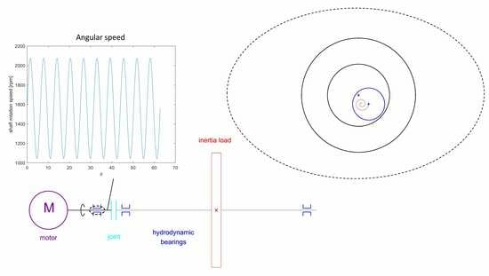
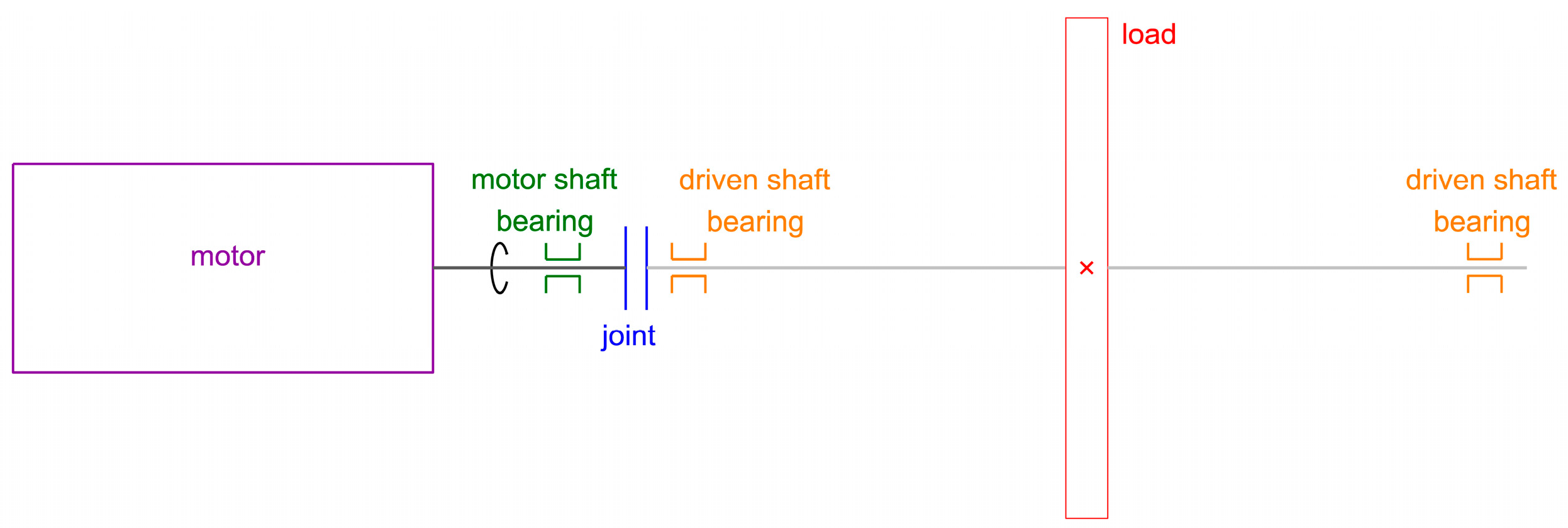
2.1. Layout of the Drive Lines

Although complexity can increase the occurrence of non-linear phenomena, related experimental findings are considered independent of the specific machine, since experimental observations belong to different types of machines. Therefore, if complex non-linear behaviors are excluded, the corresponding layouts can always be summarized by a motor matched with a shaft (with no interposed gearboxes) and its connected inertial load.
The studied elementary layout of the drive line shown in Figure 1 includes two drive shafts. The former, the motor shaft, is directly or rigidly connected to the motor, while the latter is integral with the inertial load and is referred to as the driven shaft, as it is moved by the former. Generally, in a drivetrain, driving and driven components cannot be connected directly to allow for variations in their alignment and distance. Consequently, the connection between motor and driven shafts cannot be carried out by means of rigid couplings (e.g., bolted and sleeve joints), and proper joints must be adopted (e.g., universal joints, jaw couplings, or elastic joints and splined or prismatic joints). The simple layout of Figure 1 assumes the use of elastic or universal joints to permit at least axial misalignment.
All the experimentally analyzed drivetrains can somehow be reduced to the layout scheme in Figure 1. They are driven by induction motors piloted by an inverter, which allows by means of adequate settings for the introduction of low-frequency components in the exerted mechanical torque so that it is fitted to excite the system first torsional vibration mode. Consequently, it can create working conditions characterized by the pulsating angular speed.

2.2. Lumped Parameter Model

The analysis of the drive lines characterized by the overall layout in Figure 1 requires suitable lumped parameters for each component.
From the point of view of dynamics, both drive shafts are simulated by means of their moment of inertia and mass, notated as Jm and mm for the motor shaft and as Jd and md for the driven shaft. Since the mass of the motor is partially carried out by suitable inner supports, mm includes only the remaining part which loads the motor shaft bearing. In the tested driven rotors, as in many applications, the motor inertia Jm is much lower than Jd.
The values of the above-mentioned simulation parameters relevant to the real machines tested are covered by confidentiality and cannot be reported. Differently, the data relevant to a small rotor-bearing system are reported (Table 1 and Table 2) to carry out the sample calculations proposed in Section 4.5 and Section 5.4 according to a method that has provided results in acceptable agreement with the experimental observations.
As far as torsion is concerned, the resulting lumped parameter model is a double degree of freedom (2-DOF) system referred to as a “double torsion pendulum”. The parameters of such torsional model equivalent to the rotor layout in Figure 1 are the two moments of inertia Jm and Jd and the unknown torsional stiffness Kt of the joint connecting the two inertias. Particularly, only the stiffness of the joint Kj is considered, as it is assumed to be much lower than the stiffness of each shaft. This essential assumption will be discussed again in Section 5.5.
The dynamics of such torsional system can be analyzed by solving the following system of equations:
J m d 2 θ m d t 2 + K t ( θ m θ d ) = M m J d d 2 θ d d t 2 + K t ( θ d θ m ) = M d } ,
where the angles θm and θd measure the rotation of the motor and driven shaft, respectively, while Mm and Md are the corresponding applied torques. Usually, the driven shaft torque is much lower than the motor torque, so Md = 0 is assumed.
Accordingly, the fundamental torsional vibration mode of the model is characterized by an opposing motion of the two inertias, whose natural torsional frequency is
ω t = 1 2 π K t ( J m + J d ) J m J d .

2.3. Critical Design for the Coupling of Torsional and Lateral Vibrations

It is known that a crucial condition for the stability of a rotor supported by hydrodynamic bearings occurs when its angular speed ω is twice the critical flexural speed ωf, as the onset of oil-whip may be triggered and persist at all higher speeds [29]. Such condition will be denoted as the “whip speed” in the following, while the theoretical speed of the journal precession due to oil whirl, equal to ω/2, will be referred to as the “whirl frequency”.
A torsional oscillation or “kinematic perturbation” at frequency ωt can be excited by a pulsating torque with a corresponding frequency content. If the critical torsional speed ωt is very close to the bending one ωf, at the whip speed, the frequency of such kinematic perturbation becomes ωt = ω/2. In this regard, Section 5.2 numerically proves that a kinematic perturbation has the maximum influence on bearing stability when it occurs at the whirl frequency.
Therefore, a rotor design that fulfills the condition ωt = ωf can become very critical when a source of pulsating torque with large energy acts on the rotor, as for rotation speeds higher than the whip speed torsional vibration can be effectively turned in lateral vibrations by hydrodynamic bearings.
Figure 2 shows the stability map in a scheme of a cascade plot for such critical design of the rotor-bearing system. The instable working region (in light red) exists for operational speeds higher than the critical (bending or torsional) speed up to the nominal speed ωn and can involve subsynchronous or synchronous responses, as studied in the next sections. The whip speed coincides with the second critical speed in rotors of complex machines.
In actual machines as well as in all the drive lines from which the observations are retrieved, the coupling between torsional and lateral vibrations has been spotted when the above-explained critical design condition (ωf = ωt) is met.

3. Experimental Observations

The overall interpretation of the experimental results observed in rotor-bearing systems for different applications is presented by sketching the typical trends of non-dimensional parameters. Due to confidentiality issues, the measurements carried out on actual machines and test devices cannot be presented.

3.1. Identification of the Vibrating System
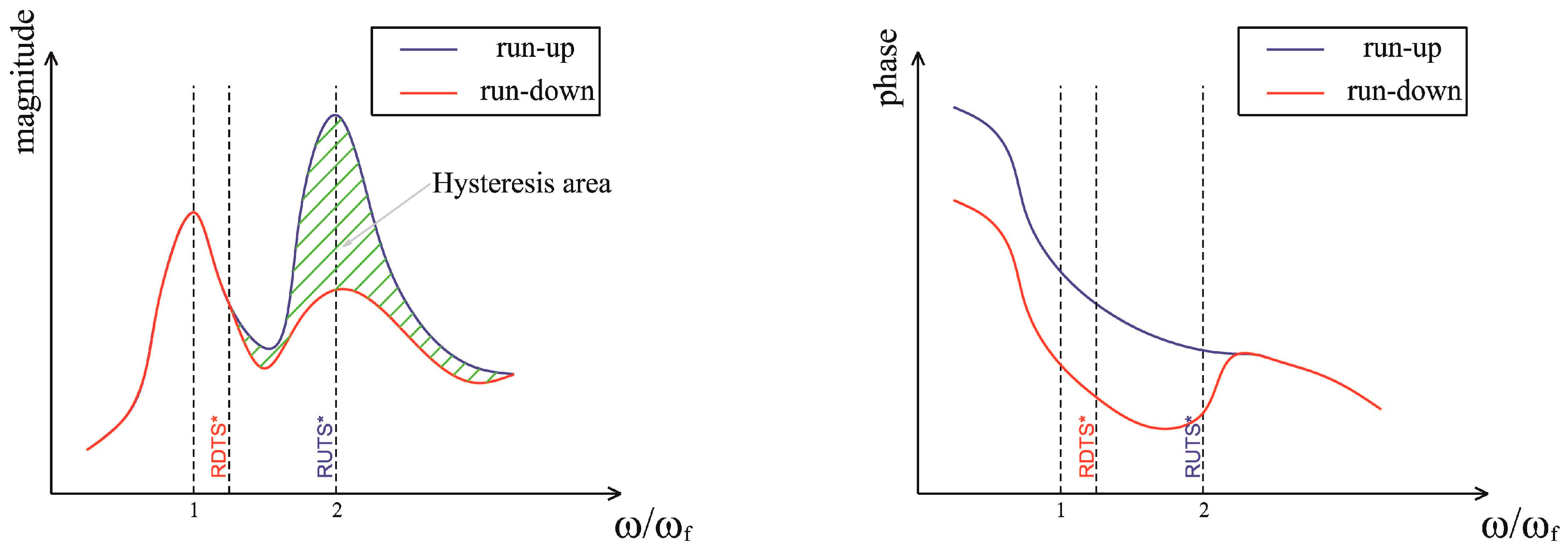
The experimental identification of the most significant lateral and torsional vibration modes (i.e., the ones more likely to affect the system operational response to a large extent) is required to ensure the complete equivalence from the point of view of the dynamic behavior between the real system and an equivalent model.
As far as torsional vibrations are concerned, the first torsional mode should be the only significant one in the system operational response. Combining this information with a survey of the shaft line actual distribution of inertia and stiffness allows for the assumption that in the first approximation, the tested systems are equivalent from the torsional point of view to the lumped parameter model of a double torsion pendulum described in Section 2.2.
In order to find the system torsional natural frequency ωt, two different experimental procedures have been used, i.e., an impact test [30] and an operational one. The impact test has been performed on the tested shaft lines at zero speed in free–free conditions by acting on the rotational degree of freedom [31]; the experimental modal analysis has allowed us to identify the first torsional vibration mode of each shaft line and to check out that the relevant shape is compatible with the equivalent torsional model. Such prior identification of the torsional vibration mode has been validated later by means of the operational test, which consists in an instantaneous shutdown of the motor during a run-up test. The shutdown causes a sudden active torque variation from a run-up average value to zero and thus introduces broadband energy into the system. Consequently, the system relevant torsional response includes a significant contribution of the structural torsional vibration mode. For some rotors, such response in a transient regime may show spectral contents with a time-dependent frequency characteristic due to the influence of the induction motor magnetic field on the overall shaft line stiffness. Particularly, such phenomenon can occur when the joint is considered (as assumed in Section 2.1), as systems with not enough stiff mechanical couplings can be extremely sensitive to the electromagnetic effect, due to the considerable interaction between the additional torsional mode and the purely structural one [32]. Furthermore, in the equivalent torsional model, the system damping from both mechanical coupling and magnetic contributions can be neglected. Indeed, the damping of mechanical coupling is negligible due to the internal damping properties of joint materials, while the magnetic one is not relevant for system natural frequencies identification, as also suggested in [32].
Once ωt has been identified and the equivalent torsional model is validated, the torsional stiffness Kt can be computed by means of Equation (2). As mentioned above, in some of the tested rotors, the magnetic field exerted by the electric motor considerably influences Kt so that the shaft structural and magnetic stiffness are comparable and perceivable coupling between structural and magnetic phenomena exists. In such cases, the magnetic stiffness and additional damping must be estimated by analyzing operational electric parameters, in agreement with [32]. By considering such an issue, the double torsion pendulum has turned out to be a valid model for all the experimental tests yielding the observations in this study.
The validity of the relevant two-degrees-of-freedom equivalent system allows for the following simplifying quantitative considerations. The torsion angles of motor and driven shafts can be different, and their angular speeds are inversely proportional to the corresponding inertia moments due to the angular moment conservation principle. Therefore, the angular speed of the motor shaft is scaled with respect to the driven shaft one of a large factor, since for the tested applications, Jm is always much lower than Jd. This allows for assuming that the driven shaft side is characterized by a negligible angular speed oscillation such that only the motor bearing is responsible for coupling torsional and lateral vibrations, as experimentally verified.

3.2. Hysteresis

Run-up and run-down tests are conducted in the whole operational field of the angular speed with constant average acceleration or deceleration intensities by driving each shaft line with a dynamic torque sufficient to significantly excite a system torsional response.
As an example, Figure 3 reports a sample of a Bode diagram of the frequency response (magnitude and phase) of the fundamental component (synchronous response) of journal vibrations. Although the relevant plots, roughly sketched to display the phenomenon effectively, are not extracted from real measurements due to confidentiality issues, their overall trend agrees with real test cases. The Bode diagram evidences the presence of localized hysteresis phenomena that make their onset in the second part of the run-up test, beyond the system first torsional critical speed. Differences between the amplitude and phase are found between run-up and run-down tests in a well-defined rotational speed range [3]. The strong amplification evidenced in Figure 3 during run-up at a rotational speed equal to 2 ωf, which considerably increases the loss of energy in the hysteresis loop, is not due to the second critical bending speed. Indeed, the relevant mode does not affect the fundamental vibration but only the vibration component at 2X frequency. Differently, the high peak in the amplitude at speed 2 ωf (whip speed) is ascribable to the jump-up phenomenon explained in Section 4.1.
Such an operational system response cannot be simulated by means of classical linear models; therefore, it is necessary to employ more advanced theories which involve fluid–structure interactions (coupling phenomena between hydrodynamic journal bearings and shaft line rotordynamic behavior), as reported in Section 4.
The difference between the run-up and run-down test curves in Figure 3, which enclose the hysteresis area highlighted by the green hatching, is an indicator of a typically non-linear response. The technical literature reports many cases of shaft-lines with no interposed gearbox where a similar behavior is described, but none of these is comparable to the presented case study. For instance, in [20], a rotor system is considered where hysteresis appears in the synchronous lateral response due to significant shaft line overhang. Indeed, it can cause large dynamic deformations.
In a rotor-bearing system, non-linearity sources can be generally reconducted to shaft line misalignments [33], tribological problems (friction in boundary, mixed or hydrodynamic lubrication regime), and material non-linearities (inhomogeneous stiffness distributions causing mechanical imbalance and coupling). In the present case, hysteresis is due to different causes. While material non-linearities are not responsible, since all the components are correctly designed and the deformations are not significant, misalignments, imbalance, and hydrodynamic bearings can be influential. Indeed, the potential unstable behavior of hydrodynamic journal bearings can cause local hysteresis, as reported in the literature [21,22], and, in turn, misalignments can influence the bearing behavior.

3.3. Vibration Analysis

For all the observation cases, time-frequency analyses of various measured signals have been performed by means of short-time Fourier transform (STFT) in the operational field of interest and in a large frequency range in order to capture all relevant spectral contents.
Figure 4 and Figure 5 sketch typical cascade plots of journal lateral vibrations in run-up and run-down tests, respectively. The STFT of the journal lateral response detected in run-up tests have evidenced that the synchronous response due to shaft imbalance represents in all the test cases the main component from an energetic point of view. For the test cases relevant to complex machines, spectral contents with lower energy appear, including 1X higher multiples (e.g., 2X, as reported in the schemes). In addition, the same cascade plots show spectral contents with significant energy in the sub-synchronous range, which exhibit lower and comparable energy levels with respect to the 1X component and its integer multiples, respectively. At speeds higher than 2 ωf, the response frequency of the detected sub-synchronous spectral content remains locked to a frequency value close to ωf. Therefore, the corresponding phenomenon can be interpreted as oil-whip. Usually, below the whip frequency, oil-whirl is visible on a 0.5X order. Differently, as shown in the sketch of Figure 4, in the analyzed cases, whip appears abruptly, so the perturbation that triggers the whip phenomenon is different from a whirl instability. Accordingly, the bearings are correctly designed so that they are sufficiently loaded to avoid conventional oil whirl instability. Moreover, such sub-synchronous spectral content modulates the synchronous response (1X), as confirmed by sidebands visible in the STFT plots and depicted in Figure 4 as dark green lines, whose energy is still perceivable. Such modulation sidebands are located symmetrically at ±ωf frequency with respect to the synchronous component (1X).
Cascade plots relevant to the STFT of the journal lateral response detected in run-down tests show a sub-synchronous spectral content analogous to the one described for run-up tests. Differently, it persists for rotational speeds under 2 ωf, as schematized in Figure 5, confirming that the oil-whip phenomenon can yield the hysteresis observed in Figure 3. Particularly, in comparison with forced run-down results, a faster decay of the whip lateral vibration is visible in free run-down tests [3], where the motor does not excite the torsional natural frequency anymore. In any case, the sub-synchronous spectral content with locked frequency persists even in the free run-down, so hysteresis may also occur in such operating condition. The persistence of sub-synchronous vibrations under the whip speed in run-down tests can also be identified by the energy levels of the sidebands (the components modulated by 1X order), which in comparison with run-up tests are higher, even at lower angular speeds.
Particularly, Figure 5 identifies the dimensionless speed boundaries RUTS* and RDTS*, where nondimensionalization is achieved by dividing the corresponding rotational speeds by the critical frequency. Such parameters allow for the localization of the hysteresis phenomenon in the Bode diagram according to Figure 3. In order to spot such hysteresis boundaries in real SFTF cascade plots (different compared to the scheme of Figure 5), the color maps must be significantly saturated in terms of the full-scale value so that the energy levels of the sub-synchronous, synchronous component (1X) and its integer multiples become less identifiable among themselves.
Moreover, in the case of forced run-down tests, the real cascade plots of lateral journal vibrations show a broadband response between the frequencies 0 and ωf at a rotational speed roughly equal to the whip speed (2 ωf). As it is also detectable in the corresponding run-up cascade plots, the broadband content is added to the schemes of both Figure 4 and Figure 5 and is probably related to a state change in bearing stability which occurs in correspondence with the onset of oil-whip conditions.
The cascade plots of torsional strain show a spectral content that exhibits an energy increase at the system first resonant frequency ωt during the run-up test for rotational speeds higher than the whip speed (defined as 2 ωf and equal to 2 ωt for the critical design at hand) and persists during run-down tests, as highlighted in the scheme of Figure 6. Such energy rise is due to a further contribution in the torsional system response that can be easily identified in the above-mentioned oil-whip phenomenon occurring at the expense of the energy dissipated by the induction motor in driving torque oscillations.
In a nutshell, the experimental observations presented in the current paragraph confirm that the oil-whip phenomenon can yield the hysteresis exhibited in Figure 3.

4. Bearing Instability and System Dynamics

4.1. Instability according HBT

Hysteresis can affect a rotor-bearing system where oil-whip occurs, since such phenomenon can develop differently in run-up and run-down phases. Accordingly, it can be characterized by distinct values of the run-up threshold speed (RUTS) and run-down threshold speed (RDTS) [23,24]. Such difference between the run-up and run-down threshold speed or energy yields the hysteresis phenomenon occurring in the presented experimental activity. Indeed, three different decays of the whip energy are detected in run-up, forced run-down, and free coast-down, as discussed in Section 3.3.
Hopf bifurcation theory (HBT) applied to rotors supported by radial hydrodynamic bearings [23,24] allows for distinguishing two different types of instabilities referred to as subcritical and supercritical bifurcation. If the conditions of supercritical bifurcation exist, when the rotor reaches a critical speed (considered as the threshold speed for the instability), the journal gradually begins to lose its stability and the amplitude of its precession motion (oil-whirl) increases continuously and progressively (ramp-up). On the contrary, in subcritical bifurcation conditions, the crossing of the critical speed (always defined as above) involves a sudden and total loss of journal stability similar to a whip (oil-whip), whose precession amplitude suddenly assumes high values, i.e., the amplitude of the oil-whip jumps up to such a large orbit that the journal tends to asymptotically approach the clearance circle (jump-up). The existence of these two important phenomena is supported by specific experimental investigation [24]. The hysteresis phenomenon can only exist in cases of subcritical bifurcation since it formally admits unstable periodic solutions from a rigorous mathematical point of view. In such case, a subcritical bifurcation profile can be determined within the hysteresis cycle. According to such profile, the stability of the rotor-bearing system between the rotational speeds (RDTS and RUTS) that delimit the cycle is determined by the magnitude of a perturbation affecting the system. Particularly, if the amplitude of the perturbation is comprised within the subcritical bifurcation profile, the journal remains stable; otherwise, the perturbation is able to activate oil-whip and a jump-up occurs in the orbit of the journal.
The jump-up occurrence can be identified in Figure 4 (run-up) and Figure 5 (forced run-down) just above the whip speed, where the already-mentioned broadband response may also be found. A sub-synchronous spectral content at a fixed frequency characterized by remarkable energy is found after such broadband excitation, at higher angular speeds, thus confirming oil-whip onset, even from the experimental data [3].

4.2. Perturbation Mechanisms

The last missing element in a consistent explanation of the phenomena experimentally highlighted in the shaft lines during run up/down tests is the nature of the perturbation cited in the previous paragraph. In the present case, the whip phenomenon appears without the previous occurrence of oil-whirl (Section 3.3). Therefore, the ramp-up cannot be the required perturbation, as in the case of lightly loaded bearings. For sufficiently loaded bearings, the perturbation may be a synchronous whirl due to the imbalance [24], and this rule holds generally. Nevertheless, since imbalance has been minimized in some tests without significant differences in the dynamic response, the instability and thus the perturbation seem to be mainly related to the torque effect and its amplification at the natural frequency. From a metrological point of view, the above-mentioned balancing has been carried out by means of a multi-plane balancing procedure in such a way that an improvement of more than one class has been obtained with reference to ISO vibration severity charts [34]. Hence, the perturbation should be linked to a dynamic or a kinematic effect of the shaft line torsion [3]. Both effects can couple torsional and lateral vibrations of the shaft line, where bending occurs at the expense of the torsional energy introduced by the electric motor.

4.3. Dynamic Perturbation

The dynamic effect is due to a rotating load caused by the driving torque and a precession motion of the two parts of the shaft. Since a kinematic perturbation causes a whirling motion with the same frequency of the perturbation (as proved in Section 5.2), such precession must occur at the torsional critical speed ωt, and the related hydrodynamic reaction must rotate at the same angular speed. In addition, the magnitude of such rotating load can be calculated by means of the following expression:
F r = Δ F r 2 cos ( ω t t + φ r ) ,
where ΔFr is the peak-to-peak amplitude of the rotating load acting on the bearings and φr its phase.
Since for the studied critical design of the shaft line, the torsional critical frequency is roughly half the shaft rotation speed (ωtω/2) at the onset of oil-whip, the load Fr can yield the effective perturbation of the bearing and affect its stability. Indeed, as well known by designers of hydrodynamic bearings for reciprocating engines and widely reported in the relevant literature, e.g., [35], such dangerous working condition, usually referred to as the “half-speed load vector” effect, causes the load capacity due to the wedge effect to vanish, so only the squeeze effect can temporarily avoid the occurrence of zero oil film thickness. Therefore, the half-speed load vector condition is acceptable in connecting rod bearing design only for limited periods of time, i.e., for short fractions of the load-cycle. Anyway, the bearings of the tested rotors are not permanently loaded by a full half-speed load; otherwise, their operation would be impossible. Indeed, they are primarily loaded by the weight of the shaft, which is the main load considered in their design phase, and by secondary dynamic loads (or perturbations) due to various causes, which include possible magnetic effects due to the electric motor, shaft imbalance, and, exactly, the rotating load due to the engine torque ripple expressed by Equation (3). Hence, the studied bearings are only partially loaded by a half-speed force. Since the oil film cannot steadily react to this load component, for sufficient entities of the torque ripple, it can lead to large perturbations of the journal position exceeding the subcritical bifurcation profile and causing bearing instability (oil-whip), as discussed in Section 4.1.

4.4. Kinematic Perturbation

The kinematic effect is the variation in the shaft rotating speed due to the external torque, which can be measured by means of a phonic wheel or computed by the torsional equivalent models (Section 2.2). Since in the forced response of the rotor-bearing system such variation occurs at a prevailing frequency, i.e., the critical torsional frequency ωt, the following expression is assumed for the journal speed or, equivalently, twice the entrainment speed of the bearings:
U = ω R + Δ U 2 cos ( ω t t + φ U ) = ω R + Δ ω 2 R cos ( ω t t + φ U ) ,
where ΔU is the (peak-to-peak) amplitude of the oil entrainment velocity variation, Δω is the corresponding angular speed rotation, and φU is a possible phase.
In agreement with the Reynolds equation, a variation in the shaft rotation speed at a given frequency yields a corresponding variation in the hydrodynamic reaction magnitude at the same frequency as expressed by Equation (3). At the same time, due to the whirling motion of the journal, which should occur at the same frequency of the kinematic perturbation, the hydrodynamic reaction direction is variable. Consequently, since such reaction is assumed to rotate at the speed ωt, which is half the rotation speed ω at the onset of oil-whip for the test rig, it can also behave as a half-speed load vector. Since the study of the effect of half-speed kinematic perturbation has not been retrieved in the literature, it is numerically studied in the following.
Since negligible angular speed oscillation involves the driven shaft (Section 3.1), the kinematic perturbation involves only the bearings supporting the motor shaft side (Figure 1). Indeed, the analysis of SFTF cascade plots of the journal vibrations in the tested cases has shown that the hysteresis phenomenon (RDTS < RUTS) is often limited to the bearings directly driven by the electric motor.

4.5. Dynamic Model of the System

The onset of instability in a rotor-bearing system corresponding to the layout of Figure 1 can be studied by means of a simple dynamic model [3], which incorporates the effects of both kinematic and dynamic perturbations. The model is simplified in that the flexural behavior is neglected and all the torsional energy is converted in a corresponding bending contribution. Such hypotheses are adopted to formulate a simplified model yielding conservative predictions convenient for verification purposes, as the involved energy conversion is ruled by the (nonlinear) behavior of the rotor structure, which is not simulated. While the driven shaft simply rotates around a fixed axis (in actual rotating machines, the motor inertia Jm is usually much lower than the load one Jd), the bearings of the motor shaft are subjected to kinematic perturbation. Section 5.2 proves by means of numerical lubrication analysis that a kinematic perturbation can induce a whirling precession occurring at the same frequency of the perturbation. Consequently, for the kinematic perturbation in Equation (4), the precession frequency of the motor axis around the fixed driven axis is ωt. Since the kinematic perturbation is usually small (as found in the tested rotors), the relevant effects are equally small despite the amplification at the oil-whip onset speed. Nevertheless, the small whirl motion, sufficient to begin the precession between the two axes, is soon amplified by the system dynamics according to the model explained below.
Therefore, it assumes that the discussed precession motion is already developed and, in addition, that angular misalignments between axes of the shaft and bearings are neglected. The corresponding dynamic rigid-body model is depicted in Figure 7, where es is the misalignment between the parallel axes, i.e., Shaft 1 and 2, which must be allowed by the joint according to the assumption in Section 2.1. The blue joint allows for their synchronous rotation θ with angular acceleration α. In turn, due to the dynamic equilibrium of the driven shaft mass md, the relative rotation θs of such two axes must occur with relative angular acceleration αs such that the dynamic perturbation load is:
F s = F 1 = F 2 = m d e s α s .
The perturbation load Fs is a tangential load acting on the joint, which results in bending stress, lateral vibrations of the shaft, and a corresponding rotating load Fr for the bearings. Such load rotates at the relative rotation speed ωs of the two shafts, whose variation can be found using the equation of dynamics for the whole shaft line, as follows:
α s = M m ( J m + J d ) α m d   e s 2 .
In the forced response of the system, the value of ωs depends on the excited mode.
Particularly, when the external torque of the electric motor excites the torsional mode, the perturbation load rotates at the torsional natural frequency. In such condition, the engine torque is determined near the torsional speed solely by the corresponding modal contribution:
M m = Δ M m 2 cos ( ω t t ) ,
where ΔMm is the (peak-to-peak) amplitude of the engine torque ripple.
Let Δω be the (peak-to-peak) amplitude of the rotational speed according to Equation (4), where φU is assumed to vanish in resonance conditions. By substituting for the time derivatives finite differences with a time increment equal to the period T of the critical torsional vibration (T = 2 π/ωt) and taking advantage of Equations (4) and (7), Equation (6) becomes
α s Δ ω s T = 1 2 Δ M m ( J m + J d ) Δ ω / T m d   e s 2 cos ( ω t t ) .
A more detailed model considers the rotor torsional flexibility (lumped in the joint) and allows for different rotational speeds (ωm and ωd) for the motor and the driven shafts, respectively. If the conservation of the angular momentum of the double torsion pendulum is also considered, Equation (8) is turned into the following expression:
α s 1 2 Δ M m 2   J m Δ ω m / T m d   e s 2 cos ( ω t t ) .
Substituting Equation (9) in Equation (5) yields the rotating load acting on the motor shaft end:
F s = 1 2 Δ M m 2   J m Δ ω m / T e s cos ( ω t t ) .
Since the torque must be constant along the shaft axis, if a bearing is located at a distance d from the motor shaft end, the dynamic perturbation Fr, defined according to Equation (3), acting on the same bearing can be found using Equation (10) by assuming that all the torque energy is turned by the structure in an equivalent bending contribution:
F r = F s e s d = 1 2 J m Δ ω m ω t / π Δ M m d cos ( ω t t + π ) .
Or, equivalently, its intensity and phase defined by Equation (3) are, respectively,
Δ F r = J m Δ ω m ω t / π Δ M m d ,
φ r = π .
Equations (11) and (13) evidence that the rotating load does not depend on the parallel misalignment es allowed by the joint, so in the first analysis (assumptions of the simplified dynamic model and angular misalignments neglected), modifications on this component are ineffective in reducing or suppressing the hysteresis phenomenon.
The influence of other dynamic contributions due to the presence of a joint is excluded. In example, for the tested drive-lines whose layouts include double Cardan joints, negligible secondary moments have been computed.
In order to provide a computational example and to fulfil confidentiality agreements, the calculations developed in Section 5.4 concern a fictitious rotor-bearing assembly (a potential small test rig). The relevant parameters, required for the above-described dynamic simulation, are provided in Table 1.
The joint stiffness Kj is determined using Equation (2) by assuming that the critical torsional frequency ωt is equal to the critical bending frequency ωf. In turn, based on motor shaft data (length 700 mm, diameter 10 mm, total mass 2.167 kg) and material (steel) assumptions, ωf is already known from the natural frequency formula of a mass-spring system, where the spring stiffness is assessed for a single-span simply supported beam.
The shaft rotation speed (1558 rpm) chosen for the analysis is the whip speed, which is double the critical torsional speed. At the chosen shaft speed, the motor shaft angular speed oscillation amplitude Δωm is computed by resorting to the equivalent torsional model (Section 2.2). For this goal, the system of Equation (1) is integrated by means of a fourth-order Runge–Kutta integration scheme by assuming Md = 0, Mm is in agreement with Equation (7), and the torsional damping factor is equal to 0.1 due to possible friction in the joint as well as material hysteresis. Δωm is retrieved from the system response in stationary conditions. The chosen motor torque ripple ΔMm substituted in Equation (7) and listed in Table 1 is sufficient to trigger instability for some bearing types.
The rotating load amplitude at the chosen shaft rotation speed, assessed by substituting the parameters of Table 1 in Equation (12), is equal to 16.5 N and is reported among the bearing calculation data in Table 2.

5. Numerical Analysis of Bearings

The dynamic and kinematic perturbations defined in Section 4.3 and Section 4.4, respectively, are turned into corresponding perturbations of the journal position by the lubricant film of the hydrodynamic bearings. Therefore, lubrication analysis is required in order to assess if a perturbation can affect journal stability [3], i.e., if the resulting journal displacement is comparable with the subcritical bifurcation profile. In order to simplify such assessment, the stability is analyzed with reference to the perturbation conditions solely at the onset of instability (at the whip speed, i.e., 1558.3 rpm for the calculation example). In other words, if the perturbation load yields large modifications of the journal displacement or causes small film thickness by itself according to the non-linear simulation method explained in the following, we assume that it can also cause the oil-whip. Such assumption has allowed us to check if the unstable behavior detected by the experimental studies is confirmed by the non-linear dynamic analysis of the lubrication problem.

5.1. Lubrication Analysis Method

In order to evaluate the effect of the perturbations, the Reynolds equation is coupled with the dynamic equation of motion of the journal, considered as a material point. Thermal effects are ignored, so the lubricant model is iso-viscous. All the classical Reynolds hypotheses, including the assumption of laminar flow, are considered valid. In such case, the thin film mechanics equation for journal bearings is:
ρ L R 2 ϑ ( H 3 12 μ L p ϑ ) + ρ L z ( H 3 12 μ L p z ) ω 2 ϑ ( ρ H ) t ( ρ H ) = 0 ,
where p is the hydrodynamic pressure, R is the journal radius, ρ is the fluid film density, ρL is the liquid phase density, H is the film thickness, ϑ is the circumferential coordinate, z is the axial coordinate, t is the time, and μL is the liquid dynamic viscosity.
The adopted solution method of Equation (14) incorporates the Jakobsson-Floberg-Olsson (JFO) boundary conditions to ensure a full dynamic simulation of cavitation or the conventional Swift–Stieber (Reynolds) conditions for quasi-static cavitation. Particularly, the results reported in Section 5.2 and Section 5.3 for the general case of a cylindrical bearing are obtained by means of the quasi-static cavitation model, while the oil film history is considered in the final results of the calculation examples in Section 5.4 for realistic bearing geometries. Details of the mathematical model, boundary conditions, as well as their FE implementation are provided in [36], with the difference being that in the present work, the dynamic equations [37] are used instead of the equilibrium equations to simulate the motion of the journal. For this goal, the journal is considered as a material point with lumped mass m, so the relevant dynamic equation system is:
F r sin θ s Ω p sin ϑ   d Ω = m   d 2 e x d t 2 F r cos θ s W + Ω p cos ϑ   d Ω = m   d 2 e y d t 2 } ,
where Ω is the developed bearing surface, (θs, Fr) are the components in polar coordinates of the dynamic perturbation acting on the bearing (Equation (11)), W is the static load (shaft weight), and ex and ey are the journal center eccentricity components in the Cartesian x, y reference frame.
The relevant journal acceleration components in Equation (15) are computed by means of standard finite differences, i.e., the second-order backward difference of journal center displacements ex and ey, respectively. Equations (14) and (15) are coupled non-linear equations solved together by means of the Newton–Raphson method at each time step. The boundaries of the journal mobility region are calculated according to the method explained in [38], which becomes essential for journal bearings designed to support actual shaft-lines.

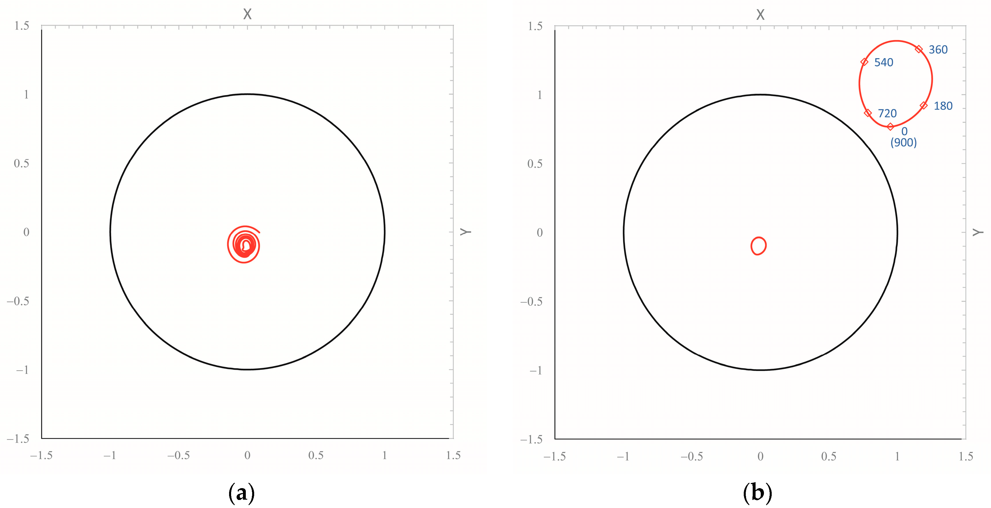
5.2. Effect of Kinematic Perturbation

As far as we know, the influence of kinematic perturbations on bearing stability has not been studied. Therefore, a non-linear stability analysis of a benchmark cylindrical bearing (for the sake of simplicity) is briefly presented in order to show the numerical evidence of such phenomenon. To this aim, Equation (4) is added to the mathematical model explained in Section 5.1 in order to simulate the entrainment speed variation with time.
The independent dimensionless parameters of the analysis are the Sommerfeld number (S), the bearing aspect ratio (L/D), the mass of the shaft (M), the ratio between the perturbation frequency and synchronous speed (ωt/ω), and the relative perturbation (peak-to-peak) amplitude (ΔU/(ωR)).
The Sommerfeld number is defined according to the following expression (typical in the lubrication analysis)
S = 30 μ ω π p m ( R c ) 2 ,
where μ is the (constant) viscosity of the lubricant, c is the bearing radial clearance, and pm is the static load (shaft weight W) per unit of the projected bearing area (pm = W/(LD)).
The shaft mass m is non-dimensionalized as follows:
M = m c ω 2 W
All the simulations in the present section are carried out for the same bearing geometry with a constant aspect ratio L/D equal to 0.3 and no imbalance.
Initially, the kinematic perturbation is excluded, and an unstable operating condition (oil-whirl) is simulated at a high Sommerfeld number (S = 1.3 × 10⁴) for M = 110.5. In such conditions, the bearing is sufficiently unloaded to develop oil-whirl with the assigned shaft mass, as shown in Figure 8. Particularly, a spiral orbit (Figure 8a) starts from an arbitrary initial journal location until a stable periodic solution with frequency ω/2 associated with supercritical bifurcation [24] (Figure 8b) is reached.
Oil-whirl instability can be suppressed by properly increasing the bearing load W for the same shaft mass m, e.g., for corresponding non-dimensional parameters S = 661 and M = 5.5, respectively. Indeed, Figure 9 shows that in such conditions (with no kinematic perturbation), the journal center path reaches the static equilibrium position near the bearing center regardless of the initial location, which is chosen at a high eccentricity (0.9) in the presented plot. The simulation in the same working conditions (S = 661 and M = 5.5) is repeated, adding a kinematic perturbation of considerable amplitude (ΔU/(ωR) = 0.5) and a perturbation frequency ratio (ωt = 0.4) near the “half-speed load vector” condition. As shown in Figure 10, a stable periodic solution is found, and oil-whirl reappears. Therefore, a kinematic perturbation of the proper amplitude and frequency can modify the bearing stability threshold. Finally, a perturbation frequency ratio (ωt = 0.5) that meets the “half-speed load vector” condition is chosen, keeping unchanged the remaining simulation parameters (S = 661, M = 5.5, ΔU/(ωR) = 0.5). Figure 11 shows a large amplification of the whirling amplitude. Hence, a half-speed kinematic perturbation is very effective in changing the stability threshold.
The oil-whirl phenomenon induced by a perturbation numerically evidenced in the last two simulations (Figure 10 and Figure 11) is very different from the classic “half-frequency oil-whirl” [39] in that the whirling precession occurs at the same frequency of the perturbation as for the forced vibration of a linear system. Therefore, such phenomenon will be referred to as “forced oil-whirl” in the following.
A campaign of simulations on the chosen cylindrical bearing (L/D = 0.3) is performed for the same working conditions (S = 661 and M = 5.5) and perturbation amplitude (ΔU/(ωR) = 0.5) but with different values of the frequency relevant to the harmonic perturbation speed in order to assess the forced response of the bearing and its sensitivity with respect to the perturbation frequency. The whirling amplitude Amax is measured by the major diameter of the nearly elliptical orbit shapes. The main result of the simulation campaign is illustrated by Figure 12, which plots the dimensionless whirl-amplitude Amax/c against the perturbation frequency ratio ωt.
As clearly suggested by Figure 12, the maximum amplification of the forced oil-whirl phenomenon is at the “half-speed load vector” condition corresponding to a perturbation frequency ωt = 0.5, while the periodic orbit amplitude coherently decays when progressively moving away from such critical frequency.
In a further simulation campaign, “half-speed load vector” conditions are maintained, i.e., the half-speed perturbation frequency is kept constant (ωt = 0.5), while the angular speed perturbation amplitude ΔU/(ωR) is varied from 0 to 0.5. Figure 13 depicts the corresponding results by plotting the output amplitude Amax/c as a function of the input one ΔU/(ωR). It shows how the trend is roughly linear below a threshold amplitude ΔU/(ωR) = 1/4. Indeed, the bearing behaves like a spring-mass linear system for small perturbations [39,40]. However, angular speed fluctuations larger than ΔU/(ωR) = 1/6 (peak-to-peak amplitude) are not likely to happen in real machines, thus suggesting that in practice, the amplitude response is always linear with the perturbation amplitude, while it is strongly non-linear with the perturbation frequency in a narrow frequency range around the oil-whirl characteristic frequency (“half-speed load vector” conditions).
In the computational example of actual bearings, the oscillation (peak-to-peak) of the driven shaft speed predicted by the equivalent torsional model is in the order of 515 rpm (see Table 1), corresponding to a dimensionless kinematic perturbation amplitude in the order of 0.33. In addition, the enhanced journal bearing design (e.g., multi-lobe or tilting-pad configurations) adopted in actual machines allows for higher stability in comparison with plain cylindrical bearings. Therefore, the influence of kinematic amplification in real-world applications is expected to also be small at the frequency of maximum amplification (ωt = 0.5).

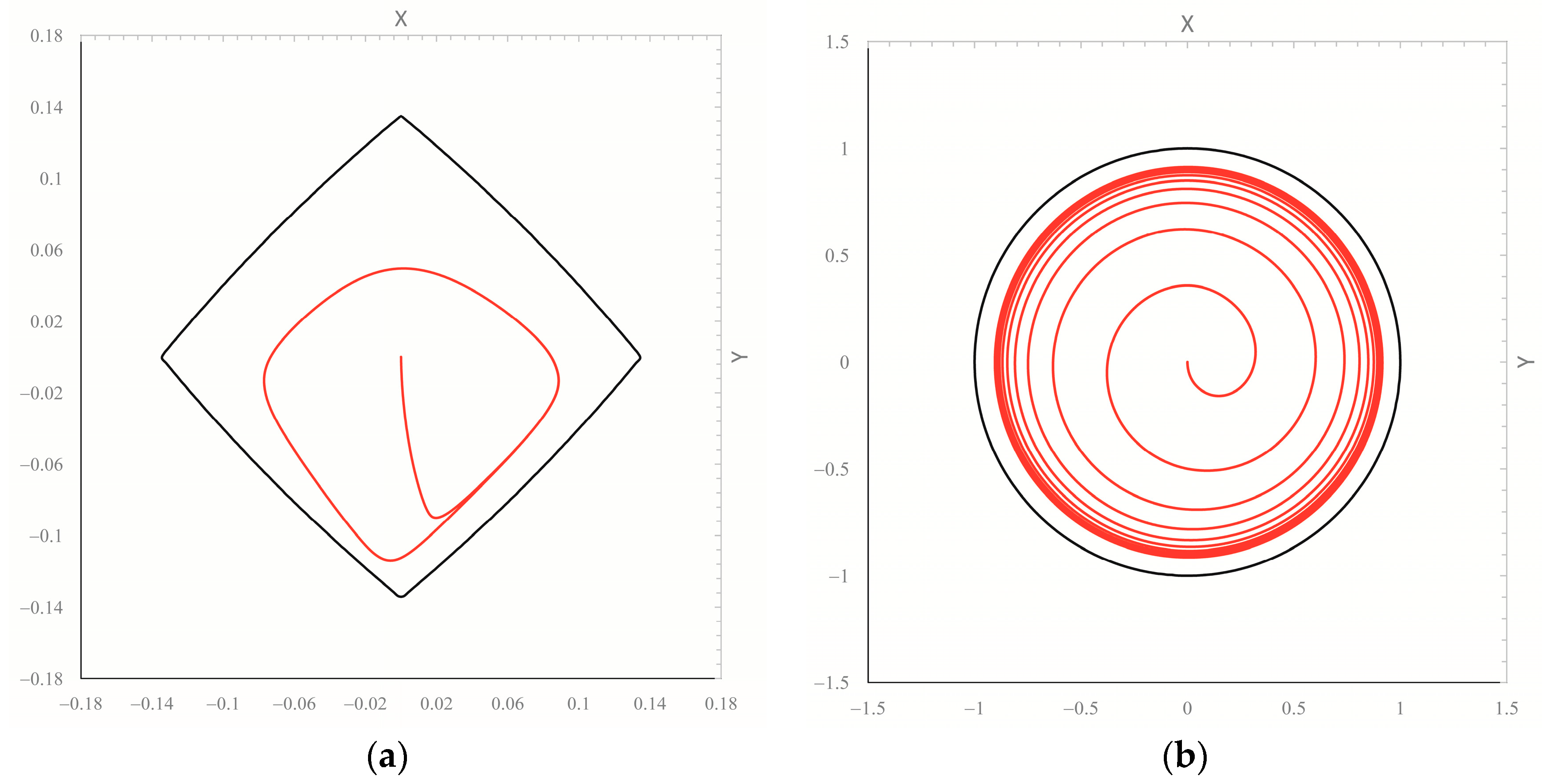
5.3. Effect of Dynamic Perturbation

In the present section, the effect of a sub-synchronous dynamic perturbation is generally evaluated for a cylindrical hydrodynamic journal bearing (with a constant aspect ratio L/D = 0.3), as carried out in Section 5.2 for the kinematic perturbation.
For this aim, further numerical simulations have been performed in order to assess if a sub-synchronous rotating force can actually affect the shaft line operational lateral response by replacing the angular speed perturbation with the dynamic one according to Equation (3). Indeed, in the technical literature, it is well known that half frequency loads cannot be supported by the wedge effect [35], but their influence on bearing stability is still unknown. Moreover, the literature about half-speed load vectors refers to the whole bearing load rotating at a half shaft revolution frequency (0.5X), while in this context, the purpose is to investigate the effect of a rotating dynamic perturbation, which is a fraction of the nominal load applied to the hydrodynamic bearing. As done for kinematic perturbation, modifications of the whirl stability threshold and the existence of half-frequency amplification under dynamic perturbation are both investigated. For this goal, a response analysis with respect to the perturbation input parameters, i.e., the frequency and amplitude of the rotating force, is carried out in the nearly stable operating conditions determined in Section 5.2, i.e., for S = 661 and M = 5.5. Then, the dynamic perturbation is applied by varying its characteristic frequency, while the amplitude is kept constant at a value two orders of magnitudes lower than the static load (i.e., Fr/W = 0.01).
Figure 14 plots the resulting trend of the dimensionless whirl-amplitude Amax/c against the perturbation frequency ratio ωt, clearly showing how for frequency ratios far from 0.5, the journal displacements are not significantly affected, while in the frequency range centered at ωt/ω = 0.5, an amplified response is obtained due to torsional-whirl occurrence. This expected finding is consistent with the literature dealing with half-speed load vectors and applies such concept to hydrodynamic bearing stability analysis. In the case of the present study, it makes up a preliminary step in the lubrication analysis of the example bearings for actual machines.

5.4. Bearing Lubrication Analysis

The lubrication analysis under dynamic loading conditions is finally applied to the motor bearing of the fictitious rotor-bearing system reported as an example. Particularly, two possible realistic geometries of the support referred to as “motor bearing” in the rotor-bearing system layout (Figure 1) are analyzed: a four-lobe journal bearing and an axially grooved cylindrical bearing.
Figure 15a defines the angular coordinate ϑ and the Cartesian reference system x, y, z used in Equations (14) and (15). As shown in this figure, the four-lobe bearing operates in a load-between-pad (LBP) configuration, and oil is supplied by means of axial grooves, which span the θg angle and the whole bearing length L in the circumferential and axial directions, respectively. The grooves are located at ϑ = 0, 90, 180, and 270 degs in the chosen polar coordinate system. This bearing is regularly designed for medium loads, as the relative eccentricity (with respect to the assembled clearance cb) is 0.67 when only the static load W is applied. The relative clearance (0.008) is perceivably higher than the usual one (0.001) due to the small dimension but still sufficient to ensure thin film lubrication [4].
The cylindrical bearing, whose clearance c is chosen to be equal to the assembled clearance cb of the four-pad bearing to carry out a reasonable comparison, is fed through a single axial groove located at ϑ = 180 degs. The span and length of the axial groove in the cylindrical bearing are the same as in the four-lobe one. The bearing cylindrical surface has a constant radius R + cb and, therefore, it is not preloaded (mp = 0, as reported in Table 2).
Both bearings, whose journal mass fraction m is W/g (g denotes the acceleration of gravity), are always statically loaded by a fraction (half) W of the total motor shaft weight, while different types of dynamic perturbations are applied in three loading conditions: in case A, only the kinematic perturbation Δω is applied according to Equation (4), with phase φU = 0; case B only considers the dynamic perturbation Fr assessed by means of Equation (11); in case C, both the kinematic and dynamic perturbations defined in the previous load cases are included. The intensity of static and dynamic loads and the rotational speed variation amplitude at the onset of oil-whip, i.e., at a shaft speed of 1558 rpm (double the torsional critical frequency), are reported in Table 2, together with all the bearing data required by the analysis. The global Reynolds number [41] is almost two orders of magnitude lower than the critical value, so the lubrication regime can be considered laminar. The resulting dynamic load diagram (for cases B and C) in Figure 15b plots the external load components in polar coordinates (θs, Fr) for different rotation angles θ of the shaft. The simulations consider the different perturbations required to cause the oil-whip, as the model focuses solely on the lubricant film and the journal center starting location is assumed at the bearing center. The structural behavior of the shaft line should be considered in the model in order to study the subsequent development of the oil-whip phenomenon after the onset and at higher speeds.
Numerical computations show that for both bearings, all three load cases admit a periodic solution, whose main features (frequency and amplitude) are reported in Table 3. The listed amplitude components are expressed in the reference frame axes x and y defined in Figure 15a and are non-dimensional values referring to bearing assembled clearance cb so that, when such components are near two units, the journal and bearing surfaces are very close to each other.
As expected in case A, the journal precession occurs at the same frequency of the applied perturbation. In agreement with the finding reported in Section 4.4, this type of response is typical of the kinematic mode of perturbation. Since the speed variation amplitude is not very significant, the relative amplitude of the orbit computed in case A is equally small despite the half frequency amplification, as also predicted in Section 4.4.
Therefore, in the next simulation including the dynamic load, i.e., case B, the kinematic perturbation is disregarded, as its effect on the journal orbit seems to be secondary. For load case B and both bearing types, Figure 16 and Figure 17 show the calculated journal orbits (red curves) inside the mobility region boundary (black curve, see Section 5.1) during the entire dynamic simulation and in stationary (periodic) conditions, respectively. In such plot, the horizontal and vertical coordinates, X and Y, respectively, are non-dimensional versions of the spatial coordinates x and y shown in Figure 15a, where X = x/cp, Y = y/cp, cp= cb/(1 − mp) (cp denotes the pad clearance, cb is the bearing clearance, and mp is the pad preload).
For the cylindrical bearing in stationary conditions (Figure 17b), the two curves are very close, and the relative amplitude components are near two units (Table 3). In addition, the relevant journal path during the whole simulation (Figure 16b) shows a spiral path typical of the instability onset. Consequently, for the cylindrical motor bearing, the resulting working conditions are critical, and the perturbation can surely activate oil-whip. For the more stable preloaded four-lobe bearing, which works at a lower Sommerfeld number, the transient orbit shape seems less critical (Figure 16a). In any case, the instability threshold is already overcome, and the perturbation causes a large orbit in stationary conditions (Figure 17a).
Unexpectedly, according to the algorithm used to analyze the journal location signals periodicity, for the cylindrical bearing, the journal response at the dynamic perturbation (case B) seems to occur at a frequency half the rotating load speed. In other words, as reported in Table 3, the period of the orbit is 0.15 s, corresponding to a frequency of 6.5 Hz, which is half the rotating load frequency ωt (13 Hz, the critical torsional speed) or, equivalently, a quarter of the shaft rotation speed ω. This behavior is consistent with the hydrodynamic lubrication principles. Indeed, when the static load prevails over the dynamic component, the resulting whirling precession is synchronous, i.e., its frequency is the same as the rotating load one. Differently, if the dynamic load is exerted by a half speed load vector, if its intensity overcomes the static load, and if instability conditions develop as in the present simulation (Figure 15b), the precession speed can occur at half the rotating load frequency (a quarter of the shaft rotation speed) so that mass conservation in the lubricant film is ensured. In addition, for this case, a deeper analysis of the journal location signals shows two repetitions of a similar pattern in the period of 0.15 s and, accordingly, the Fast Fourier Transform (FFT) analyzer finds the main frequency at 13.0 Hz. Nevertheless, the periodicity algorithm finds a journal motion component that repeats in 0.15 s, and such result is reasonable from the lubrication analysis point of view. Nevertheless, this result is not consistent with the dynamic model used for the assessment of the dynamic load, which assumes a precession of the journal at a rotation speed equal to ωt. In a nutshell, when case B loading conditions are simulated, the lubrication model may become incompatible with the overall dynamic simulation, as it does not consider the kinematic perturbation that allows for computing the rotating load in agreement with Section 4.5. Accordingly, the kinematic perturbation is essential to triggering the precession, so it is included in the last (more reasonable) load case C. In this way, lubrication analysis with consistent loading yields practically the same journal displacements obtained in case B (Figure 16 and Figure 17) without any frequency inconsistency issues. Indeed, Table 3 reports for both bearings numerically similar amplitude components in load cases B and C, while only the frequency response of case C is consistent with the assumed precession at frequency ωt, at least for the cylindrical bearing.
Since both dynamic and kinematic perturbations depend on the amplitude of the engine torque ripple ΔMm through Equations (12) and (1), respectively, threshold values of such parameter for “safe” working conditions can be determined. For this purpose, the example analysis has been repeated for several values of ΔMm until a stability condition change has been identified (over the threshold, the orbits expand very quickly with the increase in torque ripple). The relevant results show that the threshold torque ripple amplitudes are about 0.1 Nm and 0.5 Nm for the cylindrical and four-lobe bearings, respectively.
Finally, when the data of tested rotor-bearing systems are used in the simulation instead of the data of the example test rig, the proposed method, by means of the analysis of the orbits computed in load case C, predicts the onset of whip in agreement with the stability performance experimentally detected on the corresponding shaft line.

5.5. Causes of Instability and Hysteresis

As explained in detail in Section 4.5, the joint torsional stiffness Kj in Table 1 (7.41 N m/rad) used for the dynamic model and the subsequent lubrication analysis (Section 5.4) is computed according to the critical design condition (Section 2.3). In Section 2.2, in order to consider only the joint stiffness in the lumped parameter torsional model, Kj is assumed to be much lower than the torsional stiffness of the motor shaft Ktm. Since Ktm should be about 226.6 N m/rad according to the beam theory and reasonable geometrical as well as material data (second moment of mass equal to 0.001125 Kg m2 and the other data specified in Section 4.5), the initial assumption of the lumped parameter model (Kj << Ktm) is fulfilled, and the lumped parameter torsional model (double torsion pendulum) used in the present work is consistent. Nevertheless, the choice of such a low value of Kj yields an important design issue, as the joint itself determines the system dynamics. Indeed, according to the advice of joint manufacturers [42], especially for closed loop or velocity control systems, a coupling should be dimensioned to provide stiffness so that its torsional resonance frequency according to Equation (2) exceeds 300–600 Hz, depending on dynamic requirements. Such recommendation would result in a torsional stiffness much higher than the critical flexural speed of the motor shaft (13.0 Hz). Indeed, for the optimal design of the drive line at hand, the joint stiffness Kj should be at least 3957.6 Nm/rad or higher. Nevertheless such choice is suited to drive lines for specific applications, while lower design values of torsional stiffness may be chosen according to the recommendations of Section 6.5 of reference [43] by avoiding flexural and torsional frequencies of the same order of magnitude as well as by choosing operating speeds out of the regimes where the instability regions may overlap.
Hence, a vibrational problem of the type reported in the example may be caused by an inadequate design of the joint, and its potentially destructive effects can be limited by: modifying the bearing location in the drive line layout and increasing the shaft overhang to reduce the dynamic perturbation, according to Equation (12), or increasing the support stability with the choice of more stable bearing types (e.g., tilting pad bearings), higher clearances and preloads, higher supply temperatures (i.e., lower viscosities), optimal feed pressures, higher journal/bush misalignment, and larger pedestal stiffnesses [44,45].
It should be noted that the design situation described in Section 2.3 may not always be considered as an error, and thus, it is defined above as “inadequate” rather than “wrong”. Indeed, the concept of “design error” is relevant to the components used in the machinery. In specific real cases, for example, the replacement of a synchronous electric motor with an asynchronous one may completely change the dynamic requirements so that the joint torsional stiffness Kj becomes largely insufficient.
Another problem is to assess if the whip instability detected by means of the method proposed in Section 5.4 can cause the hysteresis reported in Section 3.2 or, in other words, if the numerical results agree with experimental findings when hysteresis is concerned. Indeed, such phenomenon is experimentally identified in the synchronous component of journal lateral responses in run-up and run-down tests (Figure 3), while the lubrication analysis predicts a half-frequency whirl of the shaft. This inconsistency is due to the assumption in the numerical model of disregarding both the bending deformation of the shaft, where the whole torsional energy is converted in a corresponding bending action, and the rotor imbalance.
By neglecting the flexural deformations, the lubrication model can only predict the onset of the whip on the basis of perturbations computed by an approximate dynamic model that is valid when bending does not interact with lubrication phenomena. Nevertheless, such a model cannot simulate the subsequent development of the oil-whip, which is defined by a mutual interaction between the shaft structure, primarily affected by bending deformation, and oil film.
The rotor imbalance was always present to some extent in the drive lines where journal displacement trends like the plots of Figure 3 have been measured. In an unstable bearing (where the wedge effect is ineffective), the dynamic load due to imbalance, which rotates at a synchronous speed, yields a corresponding (i.e., equally synchronous) motion component of the journal required to balance such an additional external load. Such synchronous motion must generate load-carrying capacity by means of the remaining possible mechanism, i.e., the squeeze effect. Consequently, it should allow for the limited radial motion of the journal and slightly smaller eccentricities, on average. In a nutshell, an unstable bearing of an imbalanced rotor develops two types of journal motions: the half-frequency precession typical of oil whirl, which allows for mass conservation in the lubricant film without a wedge-effect, and a synchronous motion with two components, i.e., a small radial component that balances the rotating load due to shaft imbalance by means of the squeeze effect and a tangential component that provides the required rotation of the related hydrodynamic reaction.
Such reasoning can be inferred by considering the physics of the problem, and it will be proved numerically in the next work by means of a proper coupled simulation of lubrication and structural dynamics including shaft flexural stiffness and an imbalanced load.

6. Conclusions

The conducted research activity deals with experimental observations and numerical investigation regarding the coupling phenomena between torsional and lateral vibrations in driven shaft lines with no interposed gearbox, mounted on hydrodynamic journal bearings, operated by motors with a high degree of torque irregularity, and designed with a torsional critical speed near the flexural one. In such peculiar configurations, the observed system operational behaviors exhibit anomalous trends in terms of the synchronous lateral response, which cannot be caused by the classical non-linearity sources described in the literature (e.g., shaft line overhang mounting). Particularly, a localized hysteresis phenomenon is found between run-up and run-down tests. It is due to oil-whip within the journal bearings, in agreement with the current literature findings. The onset of such instability occurs at a speed that is double the torsional frequency, so the amplification of the torsional vibration yields high irregularity in the rotation of a part of the shaft. The instability starts developing in a bearing where journal angular speed oscillation is significantly present. Such speed variation acts as a kinematic perturbation, which triggers a further perturbation of a dynamic type. In specific operating conditions, the combination of these two perturbations is turned into the perturbation of the journal motion by the lubricant film. As described in the literature, the stability margin is affected by large journal displacement perturbations, which can cause oil-whip as well as hysteresis during run up/down tests. In this way, it can be explained how torsional vibrations can affect the shaft line lateral response. Both experimental observations and numerical results support such an explanation [3]. The main experimental results relevant to drive lines for naval, automotive, and turbomachinery applications are the following:
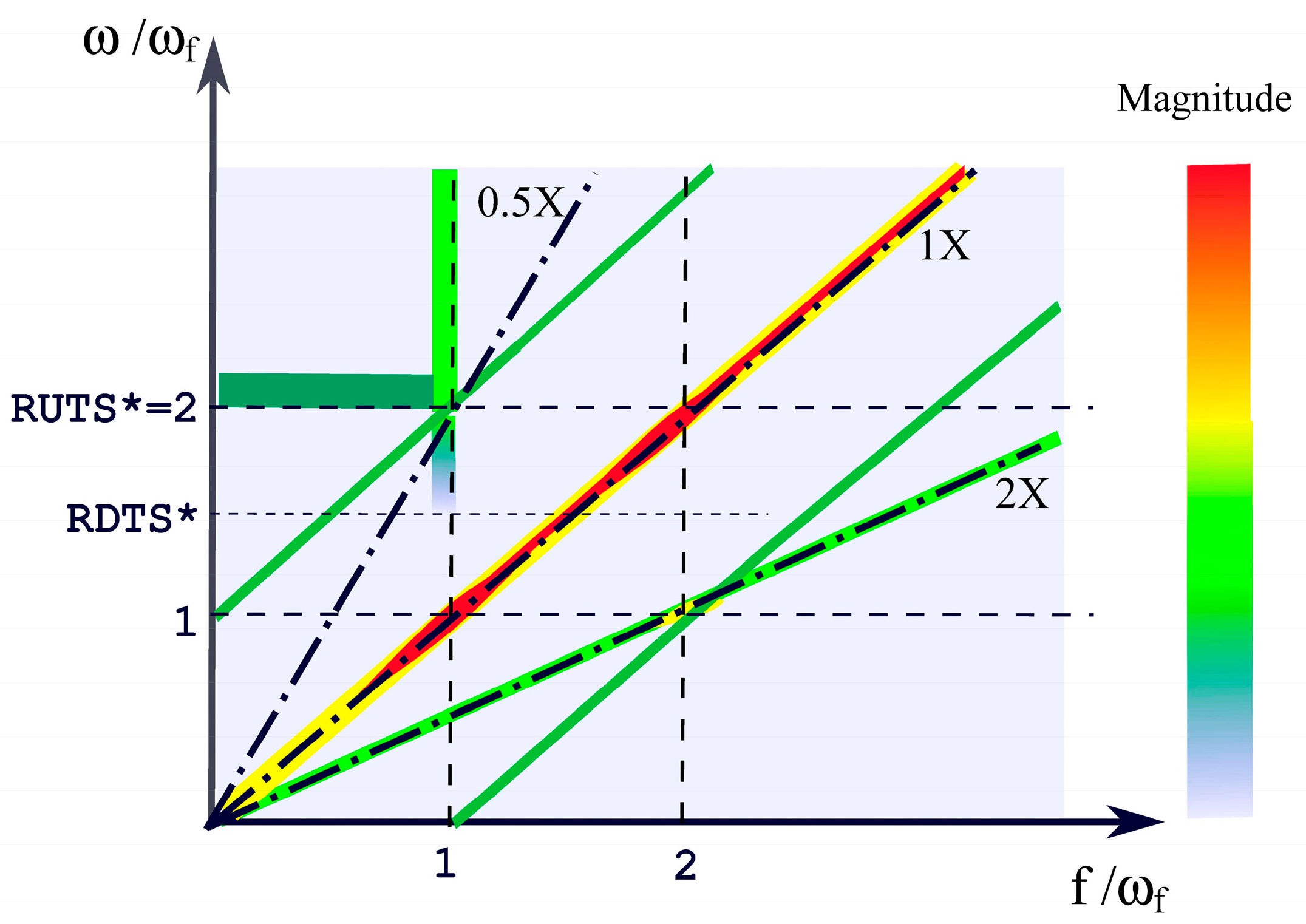
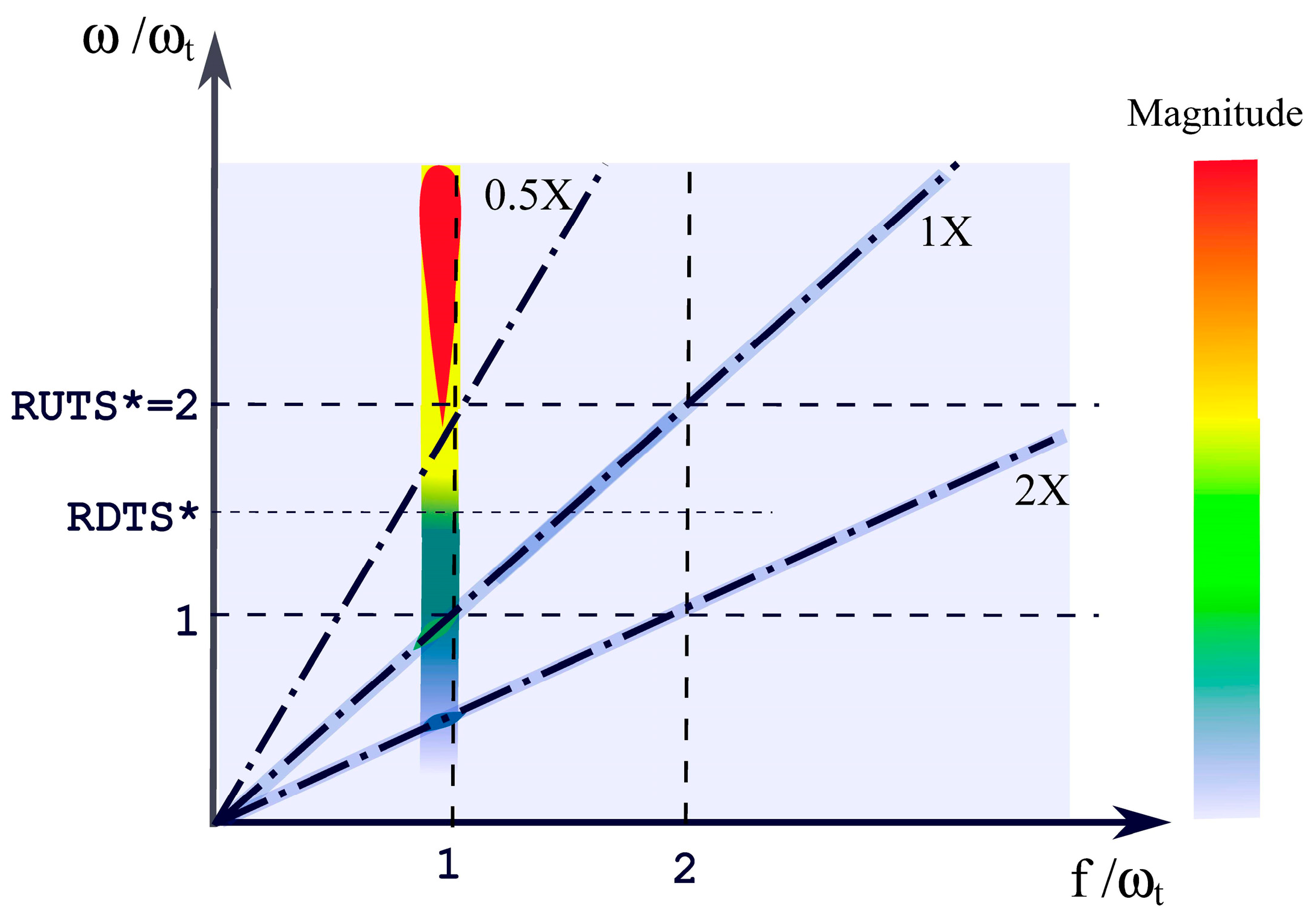
  • Oil-whip not preceded by oil-whirl can be detected in cascade plots of both lateral and torsional vibrations of journal bearings roughly at the same frequency.
  • A perceivable degree of irregularity is measured in the rotation speed of the driven shaft, i.e., the part of the shaft directly driven by the electric motor, due to the large driving torque variations.
  • Particularly, the threshold speeds RUTS and RDTS identified in cascade plots of the lateral vibrations can be different in the bearings of the driven shaft due to their rotation irregularity so that the cause of the hysteresis detected in the machine is identified according to HBT.
By means of numerical simulations, the conclusions in the following list can be drawn.
  • A kinematic perturbation can modify the stability margin of a journal bearing; such phenomenon is identified as “torsional whirl”.
  • The torsional whirl occurs at the same frequency as the excitation.
  • The journal precession due to the dynamic perturbation usually develops at the same frequency of the excitation, when the static load is higher than the rotating load, but periodic motions at half the excitation frequency may occur, when the dynamic load component prevails.
  • The maximum amplification of the journal precession whirling due to both kinematic and dynamic perturbation is found when the excitation frequency is half the rotation speed.
  • Although its isolated contribution to the journal vibration is very small, torsional whirl is required to trigger the dynamic perturbation in the dynamic model and must also be simulated in lubrication analysis to achieve consistent results.
Torsional oil-whirl is required to cause the oil-whip inception detected in experimental system responses and predicted by HBT. In the analyzed cases, the presented experimental–numerical approach can explain the significant localized hysteresis detected in the synchronous lateral shaft line response. It proves that the coupling phenomena of torsional–lateral vibrations within real-size drive lines can be linked to unstable operating conditions within hydrodynamic bearings. Therefore, the scientific content presented here, and the related verification tool, may allow for the right interpretation of the measurements and involved phenomena (e.g., the hysteresis) required to fix an “inadequate” (see Section 5.5) machine design.
In any case, the novel information provided by the mathematical model used in this work is still approximate. Indeed, since oil-whip is a cooperative phenomenon where the oil-film and structure interact, the bending of the shaft should be considered if more accurate results are required. In addition, as described in [43], mutual interactions between torsional and flexural vibrations can be due to shaft imbalance, and they can introduce structural instability if flexural and torsional natural frequencies are of the same order. Therefore, to achieve more accurate results, in future developments of the study, the mentioned structural coupling will be included in the model to analyze its interaction with bearing instability. Simulations of the shaft bending will allow for the assessment of the torque energy converted in the flexural effect by the structure, removing limiting and conservative assumptions in the model. Indeed, although more complex non-linear behaviors depending on system geometry can be neglected in this overall study, the non-linear structural coupling between bending and torsion deserves consideration when significant imbalance is present. Finally, considering shaft flexibility as well as imbalance will allow us to study the development of oil-whip, not only its onset, in order to justify its influence on the hysteresis phenomena evidenced by synchronous shaft displacement components.

Author Contributions

Conceptualization, F.A.S., P.S. and C.A.N.M.D.H.C.; methodology, F.A.S. and P.S.; software, F.A.S.; validation, F.A.S., C.A.N.M.D.H.C. and P.S.; data curation, P.S. and C.A.N.M.D.H.C.; writing—original draft preparation, F.A.S., C.A.N.M.D.H.C. and P.S.; writing—review and editing, F.A.S.; supervision, F.A.S., P.S. and A.F.M.; project administration, A.F.M. All authors have read and agreed to the published version of the manuscript.

Funding

This research received no external funding.

Data Availability Statement

The numerical data presented in this study are available on request from the corresponding author. Restrictions apply to the availability of the experimental data summarized in the relevant plots of non-dimensional quantities. Such data were obtained from third parties and are only available with their permission.

Conflicts of Interest

The authors declare no conflicts of interest.

Nomenclature

The following nomenclature is used in this manuscript:
c, cbNominal (assembled) radial clearance of the bearing
cpPad clearance
dShaft overhang
esMisalignment between the parallel drive shafts
exHorizontal component of journal eccentricity
eyVertical component (weight direction) of journal eccentricity
fFrequency
gAcceleration of gravity
mJournal lumped mass
mdMass of the driven shaft
mmMass of the motor shaft
mpPad preload
pHydrodynamic pressure
psSupply pressure
tTime
xHorizontal coordinate, bearing reference frame
yVertical coordinate (weight direction), bearing reference frame
zAxial coordinate, bearing reference frame
AmaxWhirling amplitude
DNominal diameter of the bearing
FrDynamic (rotating) load of the bearing
HFilm thickness
KtTorsional stiffness
KtmTorsional stiffness of the motor shaft
KjTorsional stiffness of the joint
MDimensionless shaft mass
MdTorque applied to the driven shaft
MmTorque applied to the motor shaft
JdInertia of the driven shaft
JmInertia of the motor shaft
LAxial length of the bearing
RJournal radius
SSommerfeld number
TPeriod of the critical torsional vibration
UPeripheral speed of the journal
WRotor weight supported by the bearing
XDimensionless horizontal coordinate, bearing reference frame
YDimensionless vertical coordinate (weight direction), bearing reference frame
αShaft angular acceleration
αsRelative angular acceleration of the drive shafts
θShaft rotation angle
θdRotation angle of the driven shaft
θgCircumferential span of the supply axial groove
θmRotation angle of the motor shaft
θsRelative rotation angle of the drive shafts
ϑCircumferential coordinate of the bearing
μLLubricant dynamic viscosity
ρFluid film density of the lubricant
ρLLiquid phase density of the lubricant
φrPhase of bearing dynamic perturbation
φUPhase of bearing kinematic perturbation
ωShaft rotation speed
ωdRotation speed of the driven shaft
ωmRotation speed of the motor shaft
ωfCritical flexural speed
ωsRelative angular speed of the drive shafts
ωtCritical torsional speed
ΔPeak-to-peak amplitude
ΩDeveloped bearing surface

References

  1. Liu, W.; Bättig, P.; Wagner, P.H.; Schiffmann, J. Nonlinear Study on a Rigid Rotor Supported by Herringbone Grooved Gas Bearings: Theory and Validation. Mech. Syst. Signal Process. 2020, 146, 106983. [Google Scholar] [CrossRef]
  2. Guenat, E.; Schiffmann, J. Dynamic Force Coefficients Identification on Air-Lubricated Herringbone Grooved Journal Bearing. Mech. Syst. Signal Process. 2020, 136, 106498. [Google Scholar] [CrossRef]
  3. Niccolini Marmont Du Haut Champ, C.A. Analysis of Dynamic Responses and Instabilities in Rotating Machinery. Ph.D. Thesis, Polytechnic School, University of Genoa, Genoa, Italy, 2022. [Google Scholar]
  4. Niccolini Marmont du Haut Champ, C.A.; Stefani, F.; Silvestri, P. Experimental and Numerical Investigation about Small Clearance Journal Bearings under Static Load Conditions. Adv. Tribol. 2020, 2020, 8844879. [Google Scholar] [CrossRef]
  5. Childs, D. Turbomachinery Rotordynamics: Phenomena, Modeling, and Analysis; Wiley-Interscience: Hoboken, NJ, USA, 1993; ISBN 978-0-471-53840-0. [Google Scholar]
  6. Al-Bedoor, B.O. Modeling the Coupled Torsional and Lateral Vibrations of Unbalanced Rotors. Comput. Methods Appl. Mech. Eng. 2001, 190, 5999–6008. [Google Scholar] [CrossRef]
  7. Kita, M.; Hataya, T.; Tokimasa, Y. Study of a Rotordynamic Analysis Method That Considers Torsional and Lateral Coupled Vibrations in Compressor Trains with a Gearbox. In Proceedings of the 36th Turbomachinery Symposium, Texas A&M University, Houston, TX, USA, 11–13 September 2007. [Google Scholar]
  8. Chiu, Y.J.; Chen, D.Z. The Coupled Vibration in a Rotating Multi-Disk Rotor System. Int. J. Mech. Sci. 2011, 53, 1–10. [Google Scholar] [CrossRef]
  9. Gosiewski, Z. Analysis of Coupling Mechanism in Lateral/Torsional Rotor Vibrations. J. Theor. Appl. Mech. 2008, 46, 829–844. [Google Scholar]
  10. Sukkar, R.; Yigit, A.S. Analysis of Fully Coupled Torsional and Lateral Vibrations of Unbalanced Rotors Subject to Axial Loads. Kuwait J. Sci. Eng. 2008, 35, 143–170. [Google Scholar]
  11. Mohiuddin, M.A.; Khulief, Y.A. Coupled Bending Torsional Vibration of Rotors Using Finite Element. J. Sound Vib. 1999, 223, 297–316. [Google Scholar] [CrossRef]
  12. Yuan, Z.; Chu, F.; Lin, Y. External and Internal Coupling Effects of Rotor’s Bending and Torsional Vibrations under Unbalances. J. Sound Vib. 2007, 299, 339–347. [Google Scholar] [CrossRef]
  13. Rao, J.S.; Shiau, T.N.; Chang, J.R. Theoretical Analysis of Lateral Response Due to Torsional Excitation of Geared Rotors. Mech. Mach. Theory 1998, 33, 761–783. [Google Scholar] [CrossRef]
  14. Patel, T.H.; Darpe, A.K. Coupled Bending-Torsional Vibration Analysis of Rotor with Rub and Crack. J. Sound Vib. 2009, 326, 740–752. [Google Scholar] [CrossRef]
  15. Muszyńska, A.; Goldman, P.; Bently, D.E. Torsional/Lateral Vibration Cross-Coupled Response Due to Shaft Anisotropy: A New Tool in Shaft Crack Detection. In Proceedings of the 5th International Conference on Vibrations in Rotating Machinery (IMechE ’92), Bath, UK, 7–10 September 1992. [Google Scholar]
  16. Genta, G. Vibration of Structures and Machines. Springer-Verlag: New York, NY, USA, 1999; ISBN 978-1-4612-1450-2. [Google Scholar]
  17. Perera, I. Theoretical and Experimental Study of Coupled Torsional—Lateral Vibrations in Rotor Dynamics. Ph.D. Thesis, Department of Mechanical Engineering, University of Calgary, Calgary, AB, Canada, 1998. [Google Scholar]
  18. Mihajlović, N.; Van De Wouw, N.; Rosielle, P.C.J.N.; Nijmeijer, H. Interaction between Torsional and Lateral Vibrations in Flexible Rotor Systems with Discontinuous Friction. Nonlinear Dyn. 2007, 50, 679–699. [Google Scholar] [CrossRef]
  19. Xiang, L.; Gao, N. Coupled Torsion–Bending Dynamic Analysis of Gear-Rotor-Bearing System with Eccentricity Fluctuation. Appl. Math. Model. 2017, 50, 569–584. [Google Scholar] [CrossRef]
  20. L’vov, M.M.; Gunter, E.J. Application of Rotor Dynamic Analysis for Evaluation of Syncronous Speed Instability and Amplitude Hysteresis at 2nd Mode for a Generator Rotor in a High-Speed Balancing Facility. In Proceedings of the ISCORMA-3, Cleveland, OH, USA, 19–23 September 2005; pp. 19–23. [Google Scholar]
  21. Mendes, R.U.; Cavalca, K.L. On the Instability Threshold of Journal Bearing Supported Rotors. Int. J. Rotating Mach. 2014, 2014, 351261. [Google Scholar] [CrossRef]
  22. Luneno, J. Coupled Vibrations in Horizontal and Vertical Rotor-Bearings Systems. Ph.D. Thesis, Luleå University of Technology, Luleå, Sweden, 2010. [Google Scholar]
  23. Wang, J.K.; Khonsari, M.M. On the Hysteresis Phenomenon Associated with Instability of Rotor-Bearing Systems. J. Tribol. 2006, 128, 188–196. [Google Scholar] [CrossRef]
  24. Wang, J.K.; Khonsari, M.M. Thermohydrodynamic Instability in Fluid-Film Bearings; Wiley: Chichester, West Sussex, UK, 2016; ISBN 9780470057216. [Google Scholar]
  25. Cui, Y.; Wang, Y.; Zhong, J. Numerical Analysis on the Nonlinear Hysteresis Phenomenon Associated with Instability of a Steam Turbine Rotor-Bearing System. In Mechanisms and Machine Science, Proceedings of the 9th IFToMM International Conference on Rotor Dynamics, Milano, Italy, 22–25 September 2014; Pennacchi, P., Ed.; Springer: Cham, Switzerland, 2015; Volume 21, p. 21. [Google Scholar]
  26. Chouchane, M.; Sghir, R. Stability and Bifurcation Analysis of a Flexible Rotor-Bearing System by Numerical Continuation. In Proceedings of the 10th International Conference on Vibrations in Rotating Machineries, London, UK, 11–13 September 2012; IMechE: London, UK, 2012; pp. 647–656. [Google Scholar]
  27. Amamou, A.; Chouchane, M. Non-Linear Stability Analysis of Floating Ring Bearings Using Hopf Bifurcation Theory. Proc. Inst. Mech. Eng. Part C J. Mech. Eng. Sci. 2011, 225, 2804–2818. [Google Scholar] [CrossRef]
  28. Wang, J.K.; Khonsari, M.M. Bifurcation Analysis of a Flexible Rotor Supported by Two Fluid-Film Journal Bearings. J. Tribol. 2006, 128, 594–603. [Google Scholar] [CrossRef]
  29. Newkirk, B.L.; Taylor, H.D. Shaft Whipping Due to Oil Action in Journal Bearings. Gen. Electr. Rev. 1925, 28, 559–568. [Google Scholar]
  30. Ewins, D.J. Modal Testing: Theory and Practice; Wiley/SEM: Bethel, NY, USA, 2009; ISBN 978-0-863-80218-8. [Google Scholar]
  31. Niccolini Marmont Du Haut Champ, C.A.; Silvestri, P. Experimental and Numerical Vibro-Acoustic Investigation on a Trimmed Car Door to Analyze Slamming Event. Appl. Acoust. 2020, 166, 107380. [Google Scholar] [CrossRef]
  32. Hauptmann, E.G.; Eckert, W.F.; Howes, B.C. The Influence on Torsional Vibration Analysis of Electromagnetic Effects across an Induction Motor Air Gap. In Proceedings of the Gas Machinery Conference 2013, Albuquerque, NM, USA, 6–9 October 2013; pp. 1–11. [Google Scholar]
  33. Niccolini Marmont Du Haut Champ, C.A.; Stefani, F.; Silvestri, P. Development of a New Test Rig for the Analysis of Hydrodynamic Bearings for Rotors of MicroGT. E3S Web Conf. 2019, 113, 4–12. [Google Scholar] [CrossRef]
  34. ISO 20816-3; Mechanical vibration. Measurement and evaluation of machine vibration, International Standard. ISO: Vernier, Geneva, Switzerland, 2022.
  35. Campbell, B.J.; Lovet, P.I.; Martint, F.A. Bearings for Reciprocating Machinery: A Review of the Present State of Theoretical, Experimental and Service Knowledge. Proc. Inst. Mech. Eng. Conf. Proc. 1967, 182 Pt 3A, 51–74. [Google Scholar] [CrossRef]
  36. Stefani, F. FEM Applied to Hydrodynamic Bearing Design. In New Tribological Ways; InTech: London, UK, 2011. [Google Scholar] [CrossRef]
  37. Brindley, J.; Savage, M.D.; Taylor, C.M. The Nonlinear Dynamics of Journal Bearings. Philos. Trans. Phys. Sci. Eng. 1990, 332, 107–119. [Google Scholar]
  38. Stefani, F. Computer-Aided Design of Pocket Elliptical Journal Bearings, Part 1: Theory. J. Adv. Mech. Des. Syst. Manuf. 2013, 7, 576–593. [Google Scholar] [CrossRef]
  39. San Andreés, L. Hydrodynamic Fluid Film Bearings and Their Effect on the Stability of Rotating Machinery. In Design and Analysis of High Speed Pumps; Educational Notes RTO-EN-AVT-143; RTO: Neuilly-sur-Seine, France, 2006; pp. 10-1–10-36. [Google Scholar]
  40. Frêne, J.; Nicolas, D.; Degueurce, B.; Berthe, D.; Godet, M. Hydrodynamic Lubrication Bearings and Thrust Bearings; Elsevier: Amsterdam, The Netherlands, 1990; ISBN 978-0-444-82366-3. [Google Scholar]
  41. Betti, A.; Forte, P.; Ciulli, E. Turbulence Effects in Tilting Pad Journal Bearings: A Review. Lubricants 2022, 10, 171. [Google Scholar] [CrossRef]
  42. Selecting for Torsional Stiffness. Available online: https://www.huco.com/design-guide/selecting-for-torsional-stiffness# (accessed on 4 March 2024).
  43. Loewy, R.G.; Piarulli, V.J. Dynamics of Rotating Shafts; The Shock and Vibration Information Center, United States Department of Defense, Navai Research Laboratory: Washington, DC, USA, 1969. [Google Scholar]
  44. Ogrodnik, P.J.; Goodwin, M.J.; Penny, J.E.T. Influence of Design Parameters on Occurrence of Oil Whirl in Rotor-Bearing Systems; NASA RP-19860020699, NASA. Lewis Research Center Instability in Rotating Machinery: Cleveland, OH, USA, 1985.
  45. Holmes, R. Oil-Whirl Characteristics of a Rigid Rotor in 360° Journal Bearings. Proc. Inst. Mech. Eng. 1963, 177, 291–307. [Google Scholar] [CrossRef]
Figure 1. Overall layout of a rotor-bearing system when the motor and load are connected by means of a joint.
Lubricants 12 00082 g001
Figure 2. Stability regions highlighted in a cascade plot scheme for the critical design condition.
Lubricants 12 00082 g002
Figure 3. Example of possible trends of the journal lateral response in run-up and run-down tests: Bode diagram of synchronous component (1X). The dimensionless run-up and run-down threshold speeds are indicated by the acronyms RUTS* and RDTS*, respectively.
Lubricants 12 00082 g003
Figure 4. Sketch of a cascade plot relevant to the time-frequency analysis (STFT) of journal lateral vibrations in run-up tests.
Lubricants 12 00082 g004
Figure 5. Sketch of a cascade plot relevant to the time-frequency analysis (STFT) of journal lateral vibrations in (forced) run-down tests.
Lubricants 12 00082 g005
Figure 6. Sketch of a cascade plot relevant to the time-frequency analysis (STFT) of the torsional strain of a driven shaft (nodal section) in (forced) run-down tests.
Lubricants 12 00082 g006
Figure 7. Dynamic perturbation model of the shaft line.
Lubricants 12 00082 g007
Figure 8. Journal center path in a cylindrical bearing (L/D = 0.3) for S = 1.3·104 and M = 110.5 (without kinematic perturbation, with oil-whirl onset): (a) Transient motion; (b) Stable periodic solution. Phase (blue values) is measured in degrees.
Lubricants 12 00082 g008
Figure 9. Journal center path during transient motion toward the equilibrium position in a cylindrical bearing (L/D = 0.3) for S = 661 and M = 5.5 (without kinematic perturbation).
Lubricants 12 00082 g009
Figure 10. Journal center path in a cylindrical bearing (L/D = 0.3) for S = 661 and M = 5.5 under kinematic perturbation with ωt = 0.4, ΔU/(ωR) = 0.5: (a) Transient motion; (b) Stable periodic solution. An orbit magnification is shown in the upper right corner, where the phase (blue values) is measured in degrees.
Lubricants 12 00082 g010
Figure 11. Journal center path in a cylindrical bearing (L/D = 0.3) for S = 661 and M = 5.5 under kinematic perturbation with ωt = 0.5, ΔU/(ωR) = 0.5: (a) Transient motion; (b) Stable periodic solution. The phase (blue values) is measured in degrees.
Lubricants 12 00082 g011
Figure 12. Frequency response to the harmonic kinematic perturbation (ΔU/(ωR) = 0.5) of a stable cylindrical bearing (L/D = 0.3, S = 661, M = 5.5).
Lubricants 12 00082 g012
Figure 13. Response to the half-speed harmonic kinematic perturbation (ωt = 0.5) of a stable cylindrical bearing (L/D = 0.3, S = 661, M = 5.5).
Lubricants 12 00082 g013
Figure 14. Frequency response to the harmonic dynamic perturbation (Fr/W = 0.01) of a stable cylindrical bearing (L/D = 0.3, S = 661, M = 5.5).
Lubricants 12 00082 g014
Figure 15. Example four-lobe journal bearing supporting the motor shaft: (a) Scheme; (b) Polar load diagram at the onset of oil-whip (1558 rpm).
Lubricants 12 00082 g015
Figure 16. Journal orbits of the example motor bearings during the whole simulation at the onset of oil-whip (1558 rpm) computed for load cases B and C: (a) four-lobe bearing; (b) cylindrical bearing.
Lubricants 12 00082 g016
Figure 17. Journal orbits of the example motor bearings in stationary (periodic) conditions at the onset of oil-whip (1558 rpm) computed for load cases B and C: (a) four-lobe bearing; (b) cylindrical bearing. The phase (blue values) is measured in degrees.
Lubricants 12 00082 g017
Table 1. Parameters of a rotor-bearing system dynamic model for the calculation example.
Parameter DescriptionSymbol [unit]Value
Joint stiffnessKj [Nm/rad]7.41
Moment of inertia of motor (or motor shaft)Jm [kg m2]0.001125
Moment of inertia of load (or driven shaft)Jd [kg m2]0.1125
Assumed motor torque ripple amplitude (peak to peak) at the simulation speedΔMm [N m]1
Computed motor shaft angular speed oscillation amplitude (peak to peak) at the simulation speedΔωm [rpm]515.46
Computed critical (natural) torsional frequency (equal to bending frequency)ωt [Hz] ([rpm]) 12.98 (779.13)
Simulation speed equal to whip speedω [rpm]1558.3
Shaft overhang (distance between motor bearing and motor shaft end)d [mm]35
Table 2. Geometrical parameters of the example motor bearings and operating conditions at the onset of oil-whip (1558 rpm).
Parameter DescriptionSymbol [unit]Value
Bearing diameterD [mm]25
Bearing lengthL [mm]35
Aspect ratioL/D1.4
Nominal (assembled) radial clearancecb [mm]0.1
Relative clearance2 cb/D0.008
Pad preload (four-lobe bearing)mp0.9
Pad preload (cylindrical bearing)mp0.0
Supply axial groove circumferential spanθg [deg]10
Supply pressureps [Pa]10,000
Oil viscosityμL [Pa s]0.0251
Rotation speed ω [rpm]1558.3
Rotor weight supported by the bearingW [N]10.6
Rotating load amplitude ΔFr [N]16.49
Speed variation amplitudeΔω [rpm]515.46
Rotating load and speed variation frequencyωt [Hz] ([rpm])13.0 (779.15)
Table 3. Periodicity parameters of the journal orbits computed for example motor bearings at the onset of oil-whip (1558 rpm) in the three load cases A, B, and C.
Bearing TypeLoad Case Frequency [Hz]Relative x AmplitudeRelative y Amplitude
four-lobeA (kinematic perturbation)13.00.140.016
four-lobeB (dynamic perturbation)13.01.611.70
four-lobeC (both perturbations)13.01.641.66
cylindricalA (kinematic perturbation)13.00.160.16
cylindricalB (dynamic perturbation)6.51.821.81
cylindricalC (both perturbations)13.01.831.82
Disclaimer/Publisher’s Note: The statements, opinions and data contained in all publications are solely those of the individual author(s) and contributor(s) and not of MDPI and/or the editor(s). MDPI and/or the editor(s) disclaim responsibility for any injury to people or property resulting from any ideas, methods, instructions or products referred to in the content.

