Erosive Wear of Structured Carbon-Fibre-Reinforced Textile Polymer Composites under Sands Blasting


Wolfson Centre for Bulk Solids Handling Technology, Faculty of Engineering & Science, University of Greenwich, Central Avenue, Chatham ME4 4TB, UK
*
Author to whom correspondence should be addressed.
Lubricants 2024, 12(3), 94; https://doi.org/10.3390/lubricants12030094
Submission received: 5 February 2024
/
Revised: 6 March 2024
/
Accepted: 13 March 2024
/
Published: 15 March 2024
Abstract
:Textile polymer composite is made of structured fibre matrix using textile technologies in fabrication, and gains benefits from strong mechanical properties with extra light weight. However, erosion behaviours and associated wear mechanisms of the composites may be influenced by the fibre structures due to heterogeneous composition and complex architectural topologies. Understanding the erosive mechanisms of the structured composites can be important, not only for preventing surface damage and loss of mechanical strength but also for improving design and fabrication of the composites. This paper presents an experimental study of erosive wear under sand blasting on 3D woven carbon-fibre-reinforced textile composites with epoxy. The architectural topology methods of the composites include non-crimped bidirectional, tufted bidirectional, 3D layer-to-layer and 3D orthogonal textile methods. The erosion tests were conducted on four impact angles (20°, 30°, 45° and 90°) under one impact velocity at 40 m/s. The study results show that the erosive mechanism of the textile composites is different from that of the neat substrate material. The observations from this study also reveal the different erosive behaviours between the composites with different fibre structures. It concludes that architectural structures can influence the erosion of a textile composite but will not result in significant differences in the wear resistance of the composites (<20%).
1. Introduction
Erosion of polymer composites due to solid particle impacts is common on many occasions, such as helicopter or wind turbine blades working in a desert, which frequently suffer from functional failures due to the damage [1]. To improve a ‘safe life’ of a polymer composite, the method of reinforcements of composites is thought to be important [2].
Erosions of materials are normally classified into two types: erosions of ductile and brittle materials in terms of wear mechanisms [3]. Erosion of ductile materials is mainly caused by plastic deformation and further material removals [4]. Erosion of brittle materials is mainly due to fatigue and crack growth [5]. Additionally, erosion of high-elastic polymers is different to the above two types of erosions and can be due to cuttings or scratchings causing deep cavities and removal of material following repeated impact of the erodent [6]. This type of failure is attributed to the relatively soft nature (low stiffness) of the hyper-elastic materials [7,8]. Erosion of carbon-fibre-reinforced polymer (CFRP) composites is hard to classify directly into any of the above categories due to its complex structures. Recently, more attention is being paid to CFRP composites because of their wide usage in the aviation industry [9,10]. In the meantime, erosion of the CFRP composites has been studied to prevent material function failures [11,12]. Vigneshwaran [13] concluded that reinforcement of fibre and filler inclusion enhanced the wear properties of the polymer composites. However, a previous review by Miyazaki [14] addressed that most polymer–matrix composites (PMCs), especially PMCs with brittle or inorganic fillers, showed larger erosion rates than the corresponding neat resins, and the increase in filler content of a composite caused an increase in erosion rate. It was also concluded in the study that PMCs with organic or ductile fillers might enhance the erosion resistance of PMCs compared with that of corresponding neat resins.
Textile polymer composites, which showed rate-dependent matrix behaviour and contained many matrix pockets, contributed to mechanical properties and thus influenced erosion across a wide range of strain rates associated with erosion at impact rates [15]. Potluri et al. [16] studied the influence of architectural topology on the impact damage of 3D woven composites and reported that the ability to withstand damage depended on the weave topology geometry of individual tows. Also, 3D woven textiles showed significant damage resistance when compared with 2D laminated composites [17]. Textile composites could benefit from rate-dependent deformation through the large angular rotation between warp and weft yarns; hence, their deformation was dominated by shear behaviour [18]. Gerlach et al. [19] published extensive experimental data on impact loading effects on different topologies of 3D woven CFRP composites. The study focused on the effect of through-thickness properties on the impact rate response of these advanced composites. It concluded that binder volume fractions had minimal effects on in-plane properties but influenced significantly through-thickness properties, thus impacting their delamination resistance. Hence, the out-of-plane properties of these advanced composites likely influenced any observed solid-particle erosion [19].
To date, there are a number of published data on such rate-dependent solid-particle erosion of these advanced textile composites [15,16,17,18,19,20,21,22,23]. Some early studies [20,21,22,23] showed that the fibre structures might influence erosive characteristics of the composites and the erosion could lie in a transition zone between brittle and ductile material behaviours. An unanswered question still remains, which is whether the carbon fibre structures can enhance the erosion resistance of the carbon PMCs or not and how. As Miyazaki [14] concluded that most CFRP composites showed a higher volumetric or weight loss than neat resins. However, a study on carbon-nanotube- (CNT) reinforced composites showed an enhanced erosion-wear performance of the composites [24,25]. Therefore, it could be that erosion of CFRP composites might depend on their reinforcement structures, or fibre size and orientations, such as nanoscale effects of the carbon nanotubes. For a large-scale effect on delamination, erosion may behave differently on the macroscale, which leads to the current study on the erosion of the interface between fibres and the substrate matrix, and formation of the fibre structures. For practices, understanding erosion in complex architectural structures will be useful in the development of PMC textile composites.
In this paper, four types of structured CFRP composites are studied in terms of erosion performances under sand blasting, which are named with the structures as 3D orthogonal, 3D layer-to-layer, bidirectional tufted and bidirectional non-crimped. Using a centrifugal erosion tester, specific erosion rates of the composites have been determined. With the photos using a scanning electrode microscope (SEM) and an optical camera, eroded surfaces of the samples show the influences of fibre structures on erosion behaviours of the composites, which may show the different erosion mechanisms of the structured CFRP composites.
2. Materials and Methods
2.1. Test Materials
The erodent used in this study was olivine sand with a median grain size (D50) of 285 µm and a size span of 200~400 μm (D10-D90), which was measured by mechanical sieving analysis. The sand used was angular in particle shape, which may represent most popular erosive particles. Particle solid density of the sand was 3.28 g/cm3, and the hardness was 6.5~7.0 (Mohs scale). The sand was dried and free flowing in the feeding process so the sand could be dispersed and accelerated evenly in the test rig.
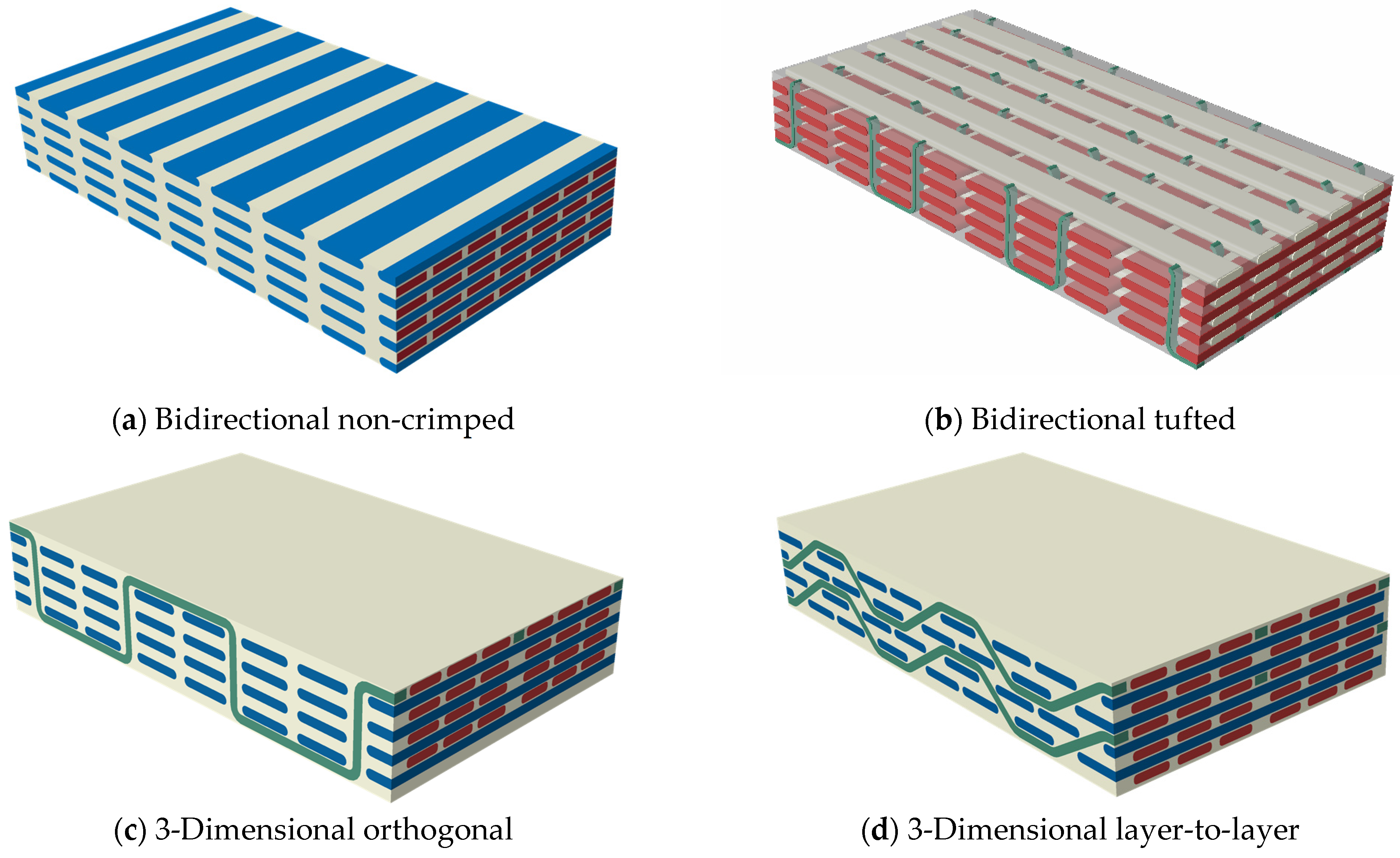
Figure 1 illustrates the four types of specimen target composites with the carbon fibre reinforcement structures; two bidirectional (BD) and two 3-dimensional (3D), which were designed and fabricated at the Engineering Composites Research Centre, School of Engineering, Ulster University [26].
The matrix/substrate material was an epoxy resin called LY564 with hardener HY 2954 (cycloaliphatic amine-based hardener). The fibre was the HexTow 12k continuous carbon fibre material, which was selected by the suitability for the composite fabrication. The composites were manufactured using the resin transfer moulding technique, and well-consolidated composite plaques were obtained. The composite sheets were subsequently cut into the right sizes (25 × 25 mm) for the erosion tests.
2.2. Centrifugal Erosion Tester
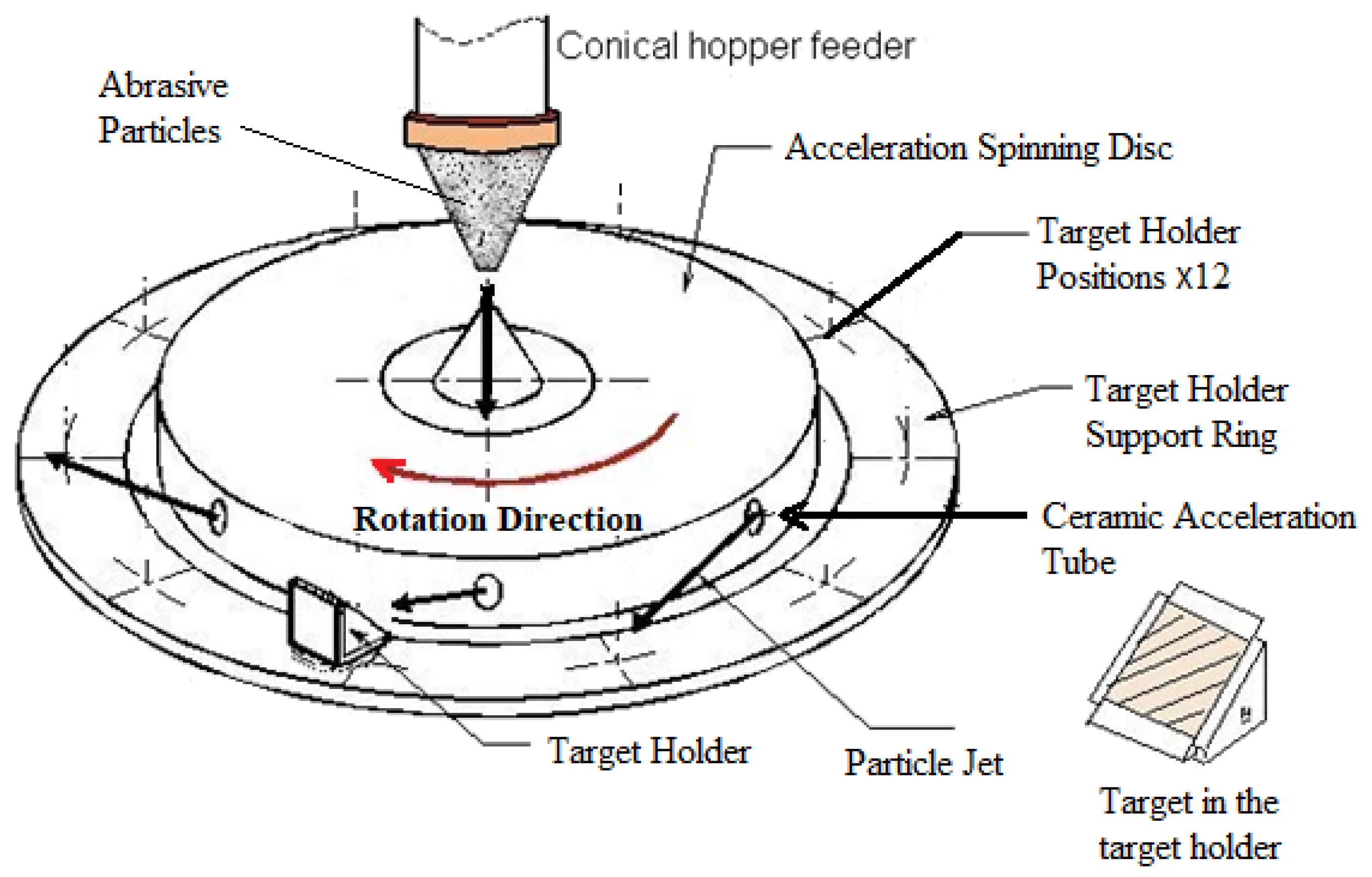
A centrifugal erosion tester was used in this study, which was developed at the Wolfson Centre, University of Greenwich, UK [27]. As shown in Figure 2, it consists of a feeder, a spinning disc with ceramic acceleration tubes inside, target holders which hold the test targets at desired angles and a control unit to drive the spinning disc at designed rotational speed so the particles can be accelerated to a designed impact velocity. Erodent particles are continuously fed into the spinning disc at the central feeding point of the disc and accelerated through the radical acceleration tubes by centrifugal force. The particle velocity is controlled by the rotational velocity of the disc. When the particles are ejected from the end of the tubes, the particles travel at the pre-set velocity and strike the target at a designed impact angle which is set by rotating the target holder. The detailed calibration of the impact velocity and impact angle can be found in the previous study [28].
The specimen targets are set around the disc on the holders, which face the direction of particle jet perpendicularly and are rotated at the designed impact angle [28]. Edge and back faces of the targets are protected from the particle jets to prevent unnecessary erosion at unwanted locations. Up to twelve target positions on the holder support ring are available in one test, which can generate erosion data of the targets at different impact angles.
2.3. Test Procedure
For the erosion tests, provisional calibrations have been undertaken, including the particle velocity (speed and exiting angle of particles) and the abrasive feeding rate [28].
Prior to the erosion test, the test targets were prepared to the same size (25 × 25 mm square and 5 mm thick) so they could be fitted into the target holder (see Figure 2). The target surface was kept at the original manufacturer’s finish conditions without any further polishing because surface polishing could damage the surface structures of the polymer composites. The test specimens were cleaned thoroughly in an ultrasonic cleaning bath for 15–20 min using isopropyl alcohol. After drying in a low-temperature heat oven at 80 °C for 15 min, the initial weight of the targets before testing was taken on an electronic balance, accurate to 0.1 mg. Two samples for each impact angle were tested simultaneously to ensure good repeatability. For each erosion test, 500 g of olivine sand was pre-weighed, dried and used for the erosion test. The erodent was fed to the tester at a feeding of 2.1 g/s using a small feeding hopper, which gave the particle concentration of approximately 0.5 kg/m3 at the impact points. Minimum of 8 repeated runs of erosion tests were performed to ensure a steady weight loss of the materials was achieved. After each test, the targets were collected and cleaned using the same cleaning procedure. Then, the weight of the targets was measured to find out the weight losses.
2.4. Test Conditions and Erosion Rate
Four different impingement angles (20°, 30°, 45° and 90°) were tested by rotating the angle of the targets horizontally. The targets were adjusted to face the particle jets perpendicularly according to the existing angle of the particle jets (see Figure 2). The rotational speed of the spinning disc was fixed to 2342 rpm (measured by a tachometer), which gave an impact velocity of particles at 40 m/s. The particle velocity was calibrated using the Ruff and Ives double-disc method [29]. In this work, the specific erosion rate (Er) of target materials is defined as the mass loss of target material per unit mass of erodent particles impinging as follows.
It is noted that in the centrifugal erosion tester the amount of erodent particles impinging on the target surface is not the same as the mass of the erodent materials fed into the tester, which is only a fraction of the total amount of the erodent particles fed, and therefore the specific erosion rate is calculated using the true mass of the particles striking on the target across the whole target width [28].
3. Results
3.1. Erosion of the Composites
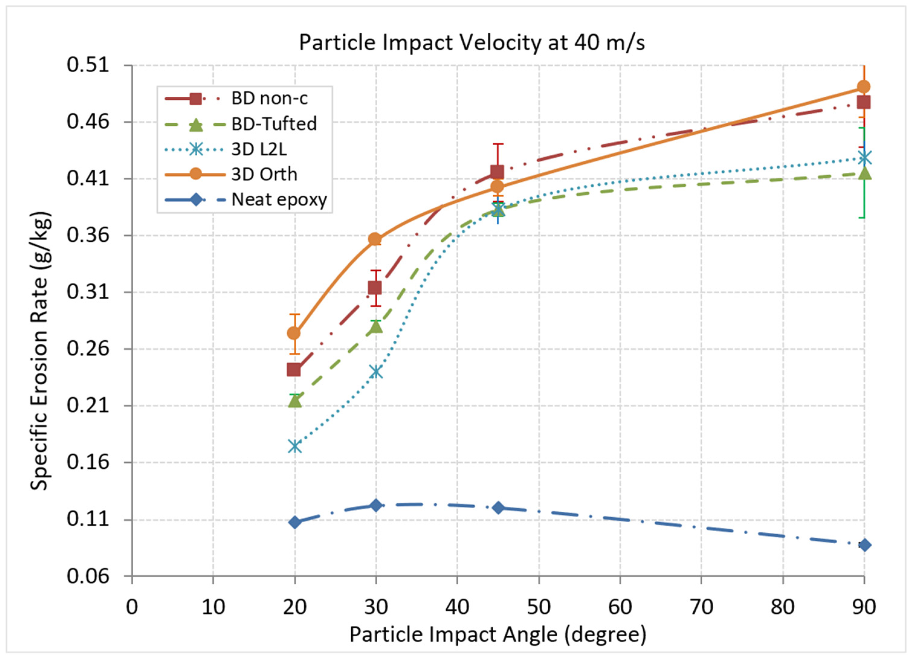
Erosion experiments were undertaken to evaluate the erosion of the CFRP textile composites. The specific erosion rates are shown in Figure 3 as a function of impact angles. The result of neat epoxy is also included for the same erosion conditions but with a smaller erodent particle size (D50 at 238 μm), which is taken from a previous study [25].
For the results shown in Figure 3, the textile composites tested clearly exhibited as brittle materials because the erosion rates raised with increased impact angles and the highest erosion rates were at the impact angle of 90°. Between the textile composite materials, erosive behaviours are broadly the same, but with a small difference in erosion rates. Compared to the neat epoxy material tested previously, the textile composites showed a change from ductile material erosion to brittle material erosion.
The test results show that the reinforcement fabric structures have little influence on the erosion behaviour of the composite. At the high-impact angles, the bidirectional (non-crimped) composite shows a relatively high erosion rate compared to the bidirectional tufted composite. Still, it has a similar erosion rate to the 3D orthogonal composite. The 3D layer-to-layer and the bidirectional tufted composites have a relatively low erosion rate. At the 20°-degree impact angle, the composites clearly show different erosion rates as influenced by the carbon fibre structures. The 3D orthogonal composite suffers from about 59% higher erosion than the 3D layer-to-layer composite. The bidirectional composites have an erosion rate in between the 3D orthogonal and the 3D layer-to-layer composite, but the bidirectional non-crimped composite generally has a higher erosion rate, which is about 12% higher than the bidirectional tufted composite but about 13% less than the 3D orthogonal composite. From the impact angle of 20° to 30°, the erosion rate has a similarly increased trend. Still, at the 45°-degree impact angle, all the composites have a closed erosion rate, which means the reinforcement structures have a similar effect.
In summary, the 3D layer-to-layer composite has a relatively good erosion resistance compared to the 3D orthogonal composite, which has a much higher erosion rate (about 60% higher). The bidirectional composites show an erosion rate in between the two 3D structured composites, but the bidirectional tufted composite shows the lowest erosion rate at the 90° impact angle. Therefore, it is believed that the structure of the carbon fibres in CFRP composites has some influence on the erosion resistance, but it will not change the type of material erosion.
3.2. Erosive Crater of the Damaged Surfaces
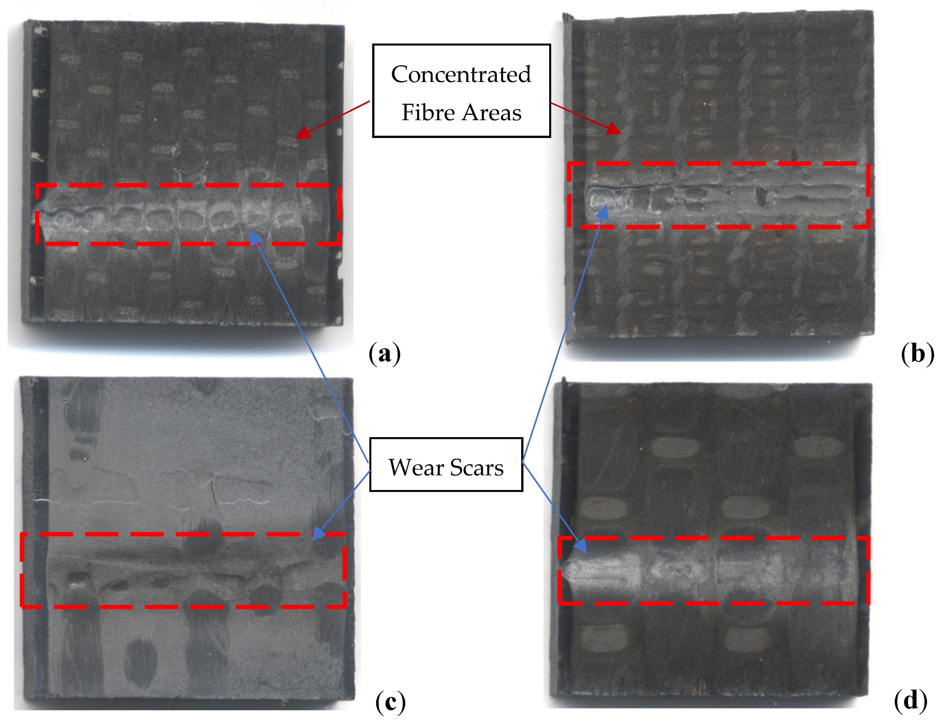
Because of the influence of the reinforcement structures on the erosion of the composite materials, the eroded surfaces of the tested materials have been examined and shown in Figure 4. The surface morphology of the tested carbon fibre/epoxy composite samples on a millimetre scale shows that a thin superficial strip of epoxy is more likely to be removed easily than the carbon fibre, although the resolution of the photos is low. It shows clearly that erosive crater patterns in macro-scale indicate that substrate material (epoxy) is lost more than the carbon fibres, as in the photos, the brighter area represents the carbon fibres, and the darker area is the epoxy resin. Obviously, the darker area has been worn more under sandblasting compared to the brighter area, and the edges (carbon fibre structures) have remained, but it does not mean the carbon fibre is more rigid.
For the bidirectional composites (Figure 4a,b), it shows that the substrate (epoxy resin) is separated by the carbon fibre structures and the losses are more likely patterned pockets rather than the 3D architectures which do not have a clear pattern on the surfaces due to a big structural interval. In the erosion results, the difference between the bidirectional and the 3D architecture composites is not clear; however, the tufted and the 3D structures have a smaller erosion rate than the non-crimped structure. The erosion craters also show that the carbon fibre is more rigid compared to the epoxy.
3.3. SEM Photos of the Eroded Composite Surfaces
From the damaged surfaces, it can be found that the erosion of textile composites can be very different due to the architectural structures at different impact angles. SEM photos of the eroded surfaces at high and low impact angles for the tested materials were taken, and the results are presented in Figure 5 for 90° and Figure 6 for 20° impact angle.
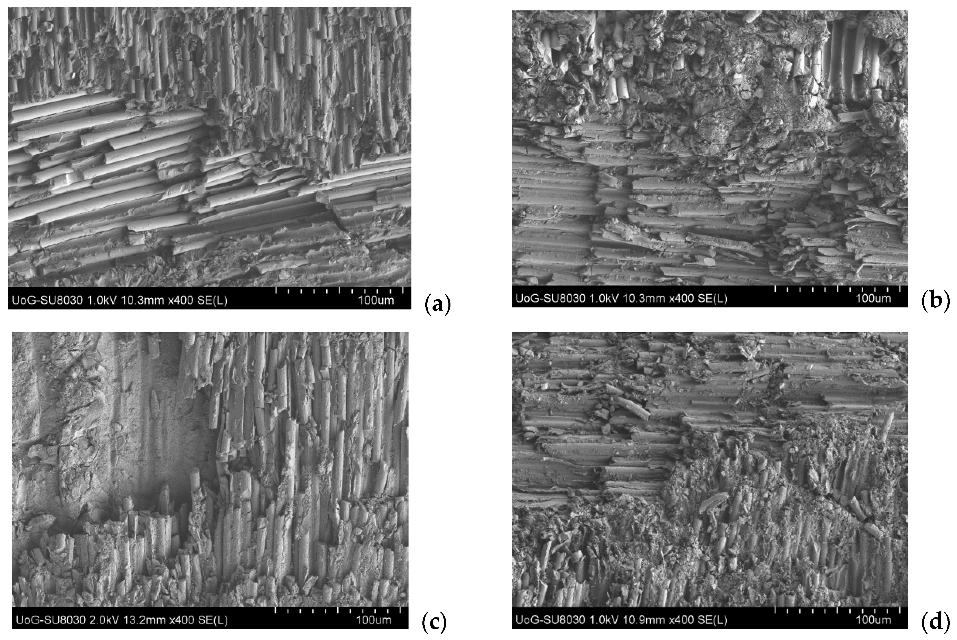
For the composites eroded at the 90° impacts as shown in Figure 5, it shows that the bidirectional composites had clearly broken fibre layers. As a comparison, the 3D structured composites also had broken fibre layers, but the broken layers are not as clear as the bidirectional composites. The results in Figure 3 show higher erosion rates for the 3D architectural materials, and they behave like brittle materials. The SEM photos clearly show the fracture of the fibres is the major erosion mechanism for the CFRP textile composites. The bidirectional tufted and 3D layer-to-layer composites have a better erosion resistance compared to the bidirectional (non-crimped) and the 3D orthogonal composites. This is thought to be due to tufted fibres and a higher density of the fibre structures [30].
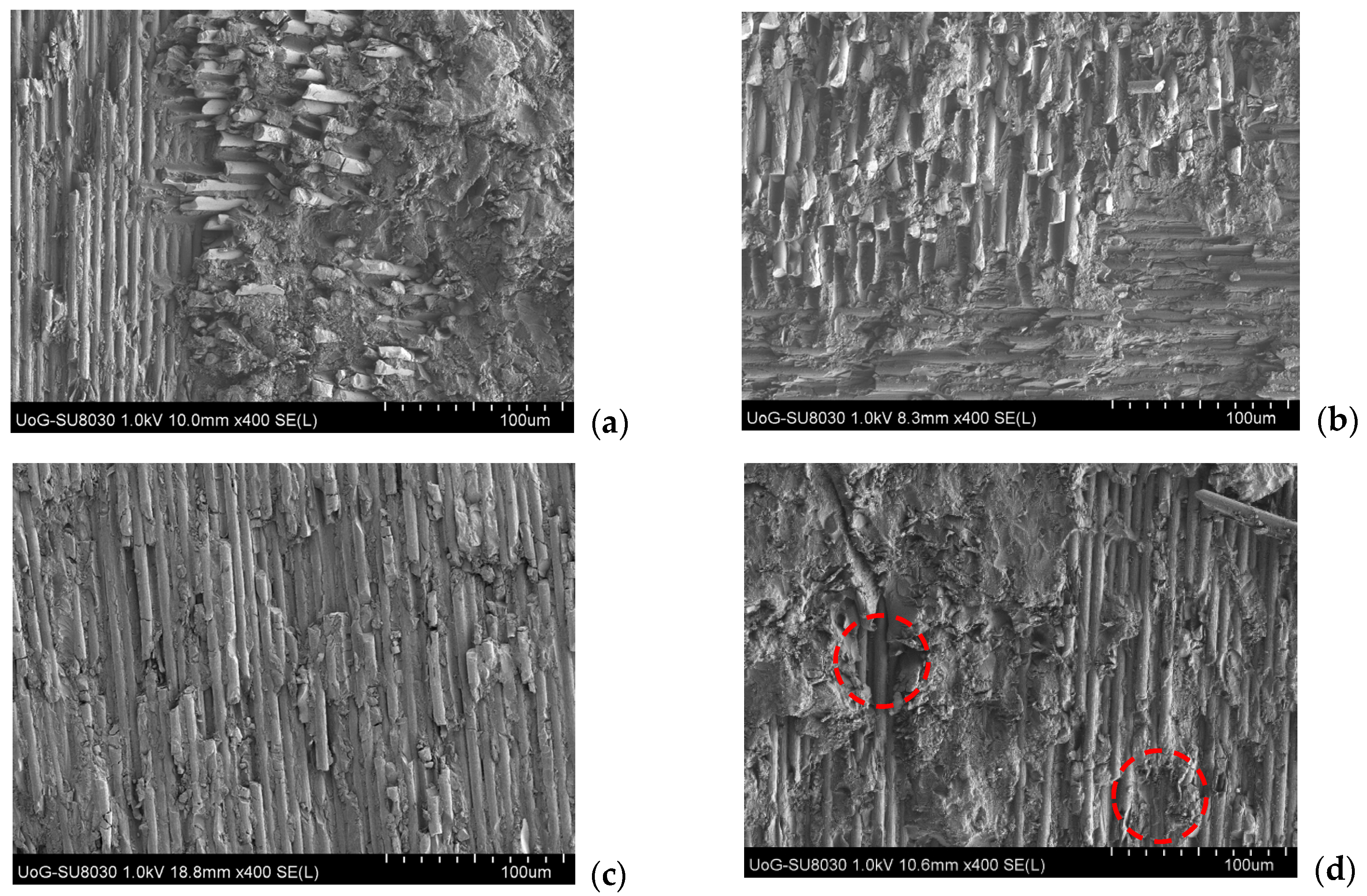
Because neat epoxy has a much better erosion resistance compared to carbon fibres, it was observed that the fibres experienced more material losses once they were broken. For the composites with denser carbon fibre architecture, epoxy contributed more wear resistance, as seen in Figure 5b,d. Therefore, the architectural topology of the textile composites predisposes the structure to more matrix-rich and matrix-pockets to have a better erosion resistance, as the fibres break down quickly. So, the broken fragment of the individual fibre bundles is the erosive mechanism for the textile composites studied. SEM photos of the eroded surfaces of the composites tested at the 20° impact angle are shown in Figure 6, which may give a different angle of the erosion mechanism. The SEM photos show little difference in the eroded surfaces in comparison with those profiles at the high impact angle. The composite materials all have a similar response across the two angles. Therefore, scratching and cutting can be the main wear mechanisms for erosive wear of these types of composite materials, as reported in the literature [14,23].
As shown in Figure 6d, deep cavities at specific localized regions (in the red circles) can be observed for the 3D layer-to-layer architecture (3D L2L), although erosion results show that the material has the lowest erosion rate compared to the other structured composites. The 3D orthogonal architecture composite has the highest erosion rate in the results. As 3D textile composites comprise of a highly heterogeneous arrangement of fibre bundles in an epoxy matrix, the erosion results are prone to be stochastic depending on how the regions of the architecture are damaged during the erosion process. If the structure of the fibre bundle is broken, there may be a significant material loss, while in the regions where fibre bundles are rigid with the epoxy, say around the binder material, there will be less material loss. Therefore, it will be important that the fibre structures are tightened with more binder materials filled in the pockets.
For the bidirectional architectures, the SEM photos show more consistent results at both high and low impingement angles, but at the high impingement angle, more aggressive loss of the fibres and deep cavities can be found compared to that at the low impact angle. It is noticed that the bidirectional tufted and the bidirectional non-crimped composites show a similar erosion rate at a low-impact angle but a large difference in the erosion rate at the high-impact angle. Hence, it suggests that the erosion mechanisms of the CFRP textile composites are mainly due to the breakdown of the fibres. The epoxy is filled in the matrix of the carbon fibres and contributes less to the erosion resistance of the composites. Therefore, the structures of the carbon fibre matrix will not have significant influences on the erosion performance of the composites, but the denser carbon fibre bundles and enhanced coverage of the epoxy give a slightly high erosion resistance of the composites. The difference in the erosion rates between the different structured composites can be up to 18%. Compared to the neat epoxy, the erosion of the CFRP textile composites is much higher, which is about 3~5 times higher than that for the neat epoxy.
3.4. SEM Photos of the Eroded Neat Epoxy Surfaces
As a comparison, SEM photos on the eroded surface of the neat epoxy polymer were taken and shown in Figure 7. The erosion results in Figure 3 indicate that the neat epoxy polymer has an erosion mechanism that is different from the CFRP composites, as the neat epoxy behaves like a ductile material. The photos in Figure 7a clearly show that the neat epoxy polymer is eroded by cutting and scratching. In the figure, it shows a long cutting crater along the material surface and almost no debris appeared in the image. With the zoomed-in photo (Figure 7b), the cutting mechanism is shown clearer. Compared to the images of CFRP composites, which show a lot of fibre debris, the eroded neat epoxy surface is clean. Thus, the SEM photos indicate the differences in erosion mechanisms between the two types of materials.
4. Discussion
The features observed in the results have been reported many times in other pieces of published work [10,16,31], such as erosion rate of carbon-fibre-reinforced materials is much higher than that of neat polymers [32], and carbon fibres are more brittle [33]. In terms of the structured CFRP composites, this discussion will focus on dependence of the carbon fibre structures and the mechanisms on the scale of the microstructural features of the two types of carbon-fibre-reinforced polymer composites, and how this affects erosive behaviours of the polymer composites.
4.1. Influences of Carbon Fibre Structures
As shown in the SEMs, the composites have a high volumetric concentration of the carbon fibres and therefore, the erosion of the carbon fibres will be the major influence on erosion of the CFRP composites. The form of carbon fibres is long and thin, and easily broken from the sides. So, the damage of carbon fibres is much higher than the damage of the substrate/matrix when the material is under impact by shaped edge solid particles. The photos in Figure 5 and Figure 6 show that the fibres are broken into small pieces and sharp cut-off edges of the broken fibres when the composite is impacted by angular particles.
The results in Figure 3 show the difference clearly at the high impact angle, in which the erosion rate of the CFRP composites is about five times more than that of the nest epoxy. The difference in the erosion rates between the bidirectional and 3D architectures is not so big, which is about 18% of the lowest value of the bidirectional tufted composite. 3D architectures show a similar erosive behaviour, in which the 3D layer-to-layer architecture shows good erosive resistance, but the 3D orthogonal architecture has a high erosion rate. The reason for this phenomenon is thought that the tightened carbon fibre bundles lead to enhanced out-of-plane properties [34], which consequently limits the erosion rate of the 3D layer-to-layer architecture composites, as shown in Figure 5 and Figure 6c,d.
It is hard to indicate the influences of carbon fibre and fibre structures on erosion behaviours of the composites directly from microstructures, as shown in the SEM photos. It still can be found that the difference between the non-crimped or orthogonal architecture and the tufted or layer-to-layer architecture. For the non-crimped or the orthogonal architecture, the carbon fibres may break in large pieces, but the tufted or the layer-to-layer architecture may provide extra space for epoxy with tightened fibre bundles. Therefore, the carbon fibres have better protection from the epoxy.
4.2. Erosive Mechanisms of the CFRP Composites
The results in Figure 3 also indicate the influence of carbon fibre structures on erosion mechanisms of the composites, although the influence is small. Generally, the CFRP composites have a similar behaviour to a brittle material due to the influence of carbon fibres. However, the types of structures may alter the erosion rate slightly because of how the fibre is broken or protected. The SEM photos show that the carbon fibres can be damaged and lost quickly once they are broken into small pieces. As the fibres are about 7–9 μm in diameter and the longitude dimension is hundreds of times bigger, it is likely the fibre is removed as a chunk once it is broken, although the fibres could be more rigid than the epoxy and its behaviour in matrix could be influenced by many other factors [35]. Unlike other brittle materials, the hardness of carbon fibre could be influenced by its orientations. Epoxy behaves differently, which is like ductile materials. At the high impact angle, the results show the difference between the fibres and epoxy polymer.
In Figure 6d, it shows the epoxy is scratched and ploughed, but the fibre is cut into large pieces and removed as whole. The SEM photo in Figure 7a shows that the epoxy is scratched and ploughed without any debris, although micro-cracking can be found in Figure 7b. For the CFRP composites, because a major part of the material is the carbon fibres, erosion of the composites will be subject to the carbon fibres and can be influenced by the fibre structures and how good the shielding is by the epoxy, but the influence of the structures will not be as big as the materials.
In terms of the carbon fibre structures, the influence will depend upon the density of the carbon fibre bundles. For the 3D architectures, the layer-to-layer architecture shows a better wear resistance than the orthogonal architecture as the layer-to-layer architecture has more protection from the tightened bundles as shown in Figure 1. For bidirectional architecture, tufted architecture does the same and is better than non-crimped architecture for the same reason. SEM photos show that the less tightened structures have less fibre density and more space to move; therefore, it could result in more material loss once the fibre is broken. Protection from the neat epoxy polymer can influence the erosion rate, although the bonding strength between the fibre and the resin can be a question [35]. The wear scars in Figure 4 show that the orientation of the carbon fibres has an influence on erosion, in which the particles with an oblique impact direction parallel to the fibres cause more damage. The SEM photos in Figure 6 show the broken fibres and the material loss because the fibre broke at a low-impact angle. The epoxy can be damaged more once the carbon fibres lose their strength due to the presence of the broken fibres.
5. Conclusions and Further Work
Erosive wear study of carbon-fibre-reinforced polymer composites was performed for a selection of plate specimens made of different structures of architectural topology, including bidirectional non-crimped, bidirectional tufted, 3-dimensional orthogonal, and 3-dimensional layer-to-layer architectures. The following conclusions were made:
- Compared to the neat epoxy, the CFRP composites showed a high erosion rate and a different erosion behaviour. The erosion of CFRP composites behaved like brittle materials, but the erosion of neat epoxy behaved like ductile materials.
- The difference in erosive behaviour between the CFRP and the neat epoxy is due to the different erosive mechanisms of the carbon fibres and the neat epoxy. The CFRP contains a high volumetric percentage of carbon fibres, but the neat epoxy does not.
- The carbon fibre structures have little influence on the erosion rate of the CFRP composites. The difference in the erosion rates between the different structured composites can be up to 18%. The tufted or layer-to-layer architecture provided better erosion resistance than the non-crimped or orthogonal architecture.
- The carbon fibre structures and the infiltration of the epoxy can influence the erosion of the composites. It is believed that better tightness of the carbon fibre bundles can provide better wear resistance, whereas the epoxy provides better protection.
- There is no significant advance for any specific structure between the different structures of the carbon fibres. However, the orientation of the carbon fibres can have an influence on the erosion, but this will need more work to prove.
This study particularly focused on the influences of carbon fibre architectures of the polymer composites on the erosive wear behaviours and mechanisms. However, a lot of unknowns and untested conditions remain in this study but can be carried out in future. Further study can be on the influences of loading ratios of the carbon fibres in the composites and the fibre orientations in the composites on wear, the information of which has been absent from this study. Application of hard fillers and the influence of bonding strength between the fibre and the resin in enhancing wear resistance performance of the woven CFRP composites can be interesting for further study.
Author Contributions
Conceptualization, T.D. and M.S.A.B.; methodology, T.D.; formal analysis, T.D.; investigation, T.D. and V.G.; data curation, T.D.; writing—original draft preparation, T.D.; writing—review and editing, T.D. and V.G.; funding acquisition, T.D. and M.S.A.B. All authors have read and agreed to the published version of the manuscript.
Funding
This research was partially funded by the Vice Chancellor’s PhD Scholarship Scheme (2012), the University of Greenwich, UK for sponsoring a PhD study programme.
Data Availability Statement
Data are contained within the article are available on request from the corresponding author due to privacy.
Acknowledgments
The authors would like to acknowledge Calvin Ralph and Alistair McIlhagger from the School of Engineering, Faculty of Computing, Eng. & Built Env., University of Ulster, who kindly provided test samples of the composite materials and knowledge of the composite manufacturing. Also, the authors would like to thank Lekshman Buji, a former student at the Wolfson Centre, for his work on SEM photography.
Conflicts of Interest
The authors declare no conflicts of interest. The funders had no role in the design of the study; in the collection, analyses, or interpretation of data; in the writing of the manuscript; or in the decision to publish the results.
References
- Tejyan, S. Effect of erosive parameters on solid particle erosion of cotton fiber–based nonwoven mat/wooden dust reinforced hybrid polymer composites. J. Ind. Text. 2022, 51 (Suppl. 2), 2514S–2532S. [Google Scholar] [CrossRef]
- Alagesan, P.K. Recent advances of hybrid fiber composites for various applications. In Hybrid Fiber Composites: Materials, Manufacturing, Process Engineering; John Wiley & Sons: Hoboken, NJ, USA, 2020; pp. 381–404. [Google Scholar]
- Tarodiya, R.; Levy, A. Surface erosion due to particle-surface interactions—A review. Powder Technol. 2021, 387, 527–559. [Google Scholar] [CrossRef]
- Akbarzadeh, E.; Elsaadawy, E.; Sherik, A.M.; Spelt, J.K.; Papini, M. The solid particle erosion of 12 metals using magnetite erodent. Wear 2012, 282, 40–51. [Google Scholar] [CrossRef]
- Finnie, I. Some reflections on the past and future of erosion. Wear 1995, 186, 1–10. [Google Scholar] [CrossRef]
- Karimi, A.; Martin, J.L. Cavitation erosion of materials. Int. Met. Rev. 1986, 31, 1–26. [Google Scholar] [CrossRef]
- Hakami, F.; Pramanik, A.; Basak, A.K. Tribology of Elastomers; Springer: Berlin/Heidelberg, Germany, 2022. [Google Scholar]
- Avcu, E.; Fidan, S.; Bora, M.Ö.; Çoban, O.; Taşkiran, İ.; Sinmazçelik, T. Solid particle erosive wear behavior of glass mat reinforced pps composites: Influence of erodent particle size, pressure, particle impingement angle, and velocity. Adv. Polym. Technol. 2013, 32, E386–E398. [Google Scholar] [CrossRef]
- Nisa, Z.U.; Chuan, L.K.; Guan, B.H.; Ayub, S.; Ahmad, F. Anti-Wear and Anti-Erosive Properties of Polymers and Their Hybrid Composites: A Critical Review of Findings and Needs. Nanomaterials 2022, 12, 2194. [Google Scholar] [CrossRef] [PubMed]
- Ozkan, D.; Gok, M.S.; Karaoglanli, A.C. Carbon fiber reinforced polymer (CFRP) composite materials, their characteristic properties, industrial application areas and their machinability. In Engineering Design Applications III: Structures, Materials and Processes; Springer: Cham, Switzerland, 2020; pp. 235–253. [Google Scholar]
- Antil, P.; Singh, S.; Kumar, S.; Manna, A.; Pruncu, C.I. Erosion analysis of fiber reinforced epoxy composites. Mater. Res. Express 2019, 6, 106520. [Google Scholar] [CrossRef]
- Boggarapu, V.; Gujjala, R.; Ojha, S. A critical review on erosion wear characteristics of polymer matrix composites. Mater. Res. Express 2020, 7, 022002. [Google Scholar] [CrossRef]
- Vigneshwaran, S.; Uthayakumar, M.; Arumugaprabu, V.; Deepak Joel Johnson, R. Influence of filler on erosion behavior of polymer composites: A comprehensive review. J. Reinf. Plast. Compos. 2018, 37, 1011–1019. [Google Scholar] [CrossRef]
- Miyazaki, N. Solid particle erosion of composite materials: A critical review. J. Compos. Mater. 2016, 50, 3175–3217. [Google Scholar] [CrossRef]
- Tejyan, S.; Patnaik, A. Erosive wear behavior and dynamic mechanical analysis of textile material reinforced polymer composites. Polym. Compos. 2017, 38, 2201–2211. [Google Scholar] [CrossRef]
- Potluri, P.; Hogg, P.; Arshad, M.; Jetavat, D.; Jamshidi, P. Influence of fibre architecture on impact damage tolerance in 3D woven composites. Appl. Compos. Mater. 2012, 19, 799–812. [Google Scholar] [CrossRef]
- Sundarakannan, R.; Balamurugan, K.; Jyothi, Y.; Arumugaprabu, V.; Sathish, T.; Mahmoud, Z.; Yousef, E.S.; Basheer, D.; Shaik, S. Importance of Fiber-/Nanofiller-Based Polymer Composites in Mechanical and Erosion Performance: A Review. J. Nanomater. 2023, 2023, 3528977. [Google Scholar] [CrossRef]
- Machado, M.; Fischlschweiger, M.; Major, Z. A rate-dependent non-orthogonal constitutive model for describing shear behaviour of woven reinforced thermoplastic composites. Compos. Part A Appl. Sci. Manuf. 2016, 80, 194–203. [Google Scholar] [CrossRef]
- Gerlach, R.; Siviour, C.R.; Wiegand, J.; Petrinic, N. In-plane and through-thickness properties, failure modes, damage and delamination in 3D woven carbon fibre composites subjected to impact loading. Compos. Sci. Technol. 2012, 72, 397–411. [Google Scholar] [CrossRef]
- Patnaik, A.; Satapathy, A.; Chand, N.; Barkoula, N.M.; Biswas, S. Solid particle erosion wear characteristics of fiber and particulate filled polymer composites: A review. Wear 2010, 268, 249–263. [Google Scholar] [CrossRef]
- Harsha, A.P.; Jha, S.K. Erosive wear studies of epoxy-based composites at normal incidence. Wear 2008, 265, 1129–1135. [Google Scholar] [CrossRef]
- Kim, A.; Kim, I. Solid particle erosion of CFRP composite with different laminate orientations. Wear 2009, 267, 1922–1926. [Google Scholar] [CrossRef]
- Barkoula, N.M.; Karger-Kocsis, J. Review processes and influencing parameters of the solid particle erosion of polymers and their composites. J. Mater. Sci. 2002, 37, 3807–3820. [Google Scholar] [CrossRef]
- Chen, J.; Trevarthen, J.A.; Deng, T.; Bradley, M.S.; Rahatekar, S.S.; Koziol, K.K. Aligned carbon nanotube reinforced high performance polymer composites with low erosive wear. Compos. Part A Appl. Sci. Manuf. 2014, 67, 86–95. [Google Scholar] [CrossRef]
- Chen, J.; Hutchings, I.M.; Deng, T.; Bradley, M.S.; Koziol, K.K. The effect of carbon nanotube orientation on erosive wear resistance of CNT-epoxy based composites. Carbon 2014, 73, 421–431. [Google Scholar] [CrossRef]
- Archer, E.; Mulligan, R.; Dixon, D.; Buchanan, S.; Stewart, G.; McIlhagger, A.T. An investigation into thermoplastic matrix 3D woven carbon fibre composites. J. Reinf. Plast. Compos. 2012, 31, 863–873. [Google Scholar] [CrossRef]
- Deng, T.; Bingley, M.S.; Bradley, M.S.A.; De Silva, S.R. A comparison of the gas-blast and centrifugal-accelerator erosion testers: The influence of particle dynamics. Wear 2008, 265, 945–955. [Google Scholar] [CrossRef]
- Deng, T.; Bingley, M.S.; Bradley, M.S.A. Influence of particle dynamics on erosion test conditions within the centrifugal accelerator type erosion tester. Wear 2001, 249, 1059–1069. [Google Scholar] [CrossRef]
- Ruff, A.W.; Ives, L.K. Measurement of solid particle velocity in erosive wear. Wear 1975, 35, 195–199. [Google Scholar] [CrossRef]
- Zaghloul, M.M.Y.; Steel, K.; Veidt, M.; Heitzmann, M.T. Wear behaviour of polymeric materials reinforced with man-made fibres: A comprehensive review about fibre volume fraction influence on wear performance. J. Reinf. Plast. Compos. 2022, 41, 215–241. [Google Scholar] [CrossRef]
- Mayana, P.; Raviprakash, A.V.; Ali, S.M.; Mohammed, R. Erosion wear behavior of polymer based hybrid composites—A review. Mater. Today Proc. 2023, 77, 424–429. [Google Scholar] [CrossRef]
- Kumar, S.; Singh, K.K. Tribological behaviour of fibre-reinforced thermoset polymer composites: A review. Proc. Inst. Mech. Eng. Part L J. Mater. Des. Appl. 2020, 234, 1439–1449. [Google Scholar] [CrossRef]
- Junaedi, H.; Albahkali, E.; Baig, M.; Dawood, A.; Almajid, A. Ductile to Brittle Transition of Short Carbon Fiber-Reinforced Polypropylene Composites. Adv. Polym. Technol. 2020, 2020, 6714097. [Google Scholar] [CrossRef]
- Aisyah, H.A.; Paridah, M.T.; Sapuan, S.M.; Ilyas, R.A.; Khalina, A.; Nurazzi, N.M.; Lee, S.H.; Lee, C.H. A comprehensive review on advanced sustainable woven natural fibre polymer composites. Polymers 2021, 13, 471. [Google Scholar] [CrossRef] [PubMed]
- Feng, P.; Ma, L.; Wu, G.; Li, X.; Zhao, M.; Shi, L.; Wang, M.; Wang, X.; Song, G. Establishment of multistage gradient modulus intermediate layer between fiber and matrix via designing double “rigid-flexible” structure to improve interfacial and mechanical properties of carbon fiber/resin composites. Compos. Sci. Technol. 2020, 200, 108336. [Google Scholar] [CrossRef]
Figure 1.
Schematic images of the CFRP composites tested and the structures of the architectural topology: (a) bidirectional non-crimped, (b) bidirectional tufted, (c) 3-dimensional orthogonal, and (d) 3-dimensional layer-to-layer architectures.
Figure 1.
Schematic images of the CFRP composites tested and the structures of the architectural topology: (a) bidirectional non-crimped, (b) bidirectional tufted, (c) 3-dimensional orthogonal, and (d) 3-dimensional layer-to-layer architectures.

Figure 2.
Schematic diagram of the centrifugal erosion tester and a target holder [27].
Figure 2.
Schematic diagram of the centrifugal erosion tester and a target holder [27].

Figure 3.
Specific erosion rates of bidirectional non-crimped, bidirectional tufted, 3D orthogonal, 3D layer-to-layer architecture carbon-fibre-reinforced epoxy composites and neat epoxy at four impact angles of 20°, 30°, 45° and 90°.
Figure 3.
Specific erosion rates of bidirectional non-crimped, bidirectional tufted, 3D orthogonal, 3D layer-to-layer architecture carbon-fibre-reinforced epoxy composites and neat epoxy at four impact angles of 20°, 30°, 45° and 90°.

Figure 4.
Eroded surfaces impacted at 90o-degree impact angle for: (a) bidirectional non-crimped, (b) bidirectional tufted, (c) 3D orthogonal, and (d) 3D layer-to-layer architectures. The depth of the craters is about 1 mm approximately in the middle, although it has not been shown in the diagram.
Figure 4.
Eroded surfaces impacted at 90o-degree impact angle for: (a) bidirectional non-crimped, (b) bidirectional tufted, (c) 3D orthogonal, and (d) 3D layer-to-layer architectures. The depth of the craters is about 1 mm approximately in the middle, although it has not been shown in the diagram.

Figure 5.
SEMs of the eroded surfaces: (a) bidirectional non-crimped, (b) bidirectional tufted, (c) 3-dimensional orthogonal, and (d) 3-dimensional layer-to-layer composites eroded by olivine sands at 40 m/s and 90° degree impact.
Figure 5.
SEMs of the eroded surfaces: (a) bidirectional non-crimped, (b) bidirectional tufted, (c) 3-dimensional orthogonal, and (d) 3-dimensional layer-to-layer composites eroded by olivine sands at 40 m/s and 90° degree impact.

Figure 6.
SEMs of the eroded surfaces: (a) bidirectional non-crimped, (b) bidirectional tufted, (c) 3-dimensional orthogonal, and (d) 3-dimensional layer-to-layer composites eroded by olivine sands at 40 m/s and 20° degree impact (where in red circle, more resin material was removed).
Figure 6.
SEMs of the eroded surfaces: (a) bidirectional non-crimped, (b) bidirectional tufted, (c) 3-dimensional orthogonal, and (d) 3-dimensional layer-to-layer composites eroded by olivine sands at 40 m/s and 20° degree impact (where in red circle, more resin material was removed).

Figure 7.
SEM photos of the eroded surfaces of neat epoxy polymer: (a) a large scale, (b) zoomed in, eroded by olivine sands at 40 m/s and 20° degree impact.
Figure 7.
SEM photos of the eroded surfaces of neat epoxy polymer: (a) a large scale, (b) zoomed in, eroded by olivine sands at 40 m/s and 20° degree impact.

Disclaimer/Publisher’s Note: The statements, opinions and data contained in all publications are solely those of the individual author(s) and contributor(s) and not of MDPI and/or the editor(s). MDPI and/or the editor(s) disclaim responsibility for any injury to people or property resulting from any ideas, methods, instructions or products referred to in the content. |
© 2024 by the authors. Licensee MDPI, Basel, Switzerland. This article is an open access article distributed under the terms and conditions of the Creative Commons Attribution (CC BY) license (https://creativecommons.org/licenses/by/4.0/).
Share and Cite
MDPI and ACS Style
Deng, T.; Garg, V.; Bradley, M.S.A. Erosive Wear of Structured Carbon-Fibre-Reinforced Textile Polymer Composites under Sands Blasting. Lubricants 2024, 12, 94. https://doi.org/10.3390/lubricants12030094
AMA Style
Deng T, Garg V, Bradley MSA. Erosive Wear of Structured Carbon-Fibre-Reinforced Textile Polymer Composites under Sands Blasting. Lubricants. 2024; 12(3):94. https://doi.org/10.3390/lubricants12030094
Chicago/Turabian StyleDeng, Tong, Vivek Garg, and Michael S.A. Bradley. 2024. "Erosive Wear of Structured Carbon-Fibre-Reinforced Textile Polymer Composites under Sands Blasting" Lubricants 12, no. 3: 94. https://doi.org/10.3390/lubricants12030094
Note that from the first issue of 2016, this journal uses article numbers instead of page numbers. See further details here.