Analysis of Dynamic Wear Characteristics of Joint Contact Friction Pair of Excavators Working Device
by
 ,
,
Xuehui Chen
1,2, 
Lei Zhang
1,2,
Wei Li
3,
Zijian Wang
4,
Zhengbin Zhang
1,
Ting Gao
1,2 and
Wei Liu
1,2,* 1
School of Mechanical and Electrical Engineering, Anhui Jianzhu University, Hefei 230601, China
2
Anhui Province Key Laboratory of Critical Friction Pair for Advanced Equipment, Hefei 230601, China
3
Hefei Bolin Advanced Materials Company Limited, Hefei 230601, China
4
School of Automotive and Transportation Engineering, Hefei University of Technology, Hefei 230009, China
*
Author to whom correspondence should be addressed.
Lubricants 2024, 12(4), 113; https://doi.org/10.3390/lubricants12040113
Submission received: 5 March 2024
/
Revised: 19 March 2024
/
Accepted: 26 March 2024
/
Published: 29 March 2024
Abstract
:The working device of an excavator in construction machinery is prone to damage and wear under ordinary working conditions. Based on a model of an excavator under typical working conditions, the dynamic load-bearing situation of the three main joint friction subsets of the working device is simulated by using the virtual prototype technology; the location of the functional device with high stress is identified based on finite element analysis, and the correctness of the simulation results is verified by designing strain gauges. Based on this, the dynamic contact stress variation law of the contact surface of the end-face friction subsets was explored, and the end-face wear depth was calculated by combining Archard wear theory and finite element wear simulation technology; the specimens were worn on the end-face wear tester, and the surface wear was observed under the scanning electron microscope to summarize the wear mechanism and analyze the element content changes of the worn surface. The results show that the three main joints of the working device produce large dynamic fluctuations and are prone to wear, and the destructive degree is more prominent; the wear process is accompanied by higher temperatures, fatigue wear, and abrasive wear on the wear surface, and the wear depth value of the right end face is significantly larger than that of the left end face. This method has a significant reference value for reliability analysis and optimization improvement when using construction machinery’s main joint friction pairs.
1. Introduction
Excavators are widely used in infrastructure construction, and due to the long-term harsh operating environment, impact vibration, and alternating load, the work device joints are prone to fatigue fracture, surface material loss, severe wear at the end friction sub-place, and other undesirable phenomena, which have a substantial impact on the regular operation and use of the mechanical machine system [1]. At the same time, the work device joint frictional sub-division of the operation process does irregular contact collision movement, resulting in higher temperatures that quickly lead to the failure of surface lubrication devices, thereby increasing the contact surface friction and reducing the service life.
Many scholars have investigated destructive work devices of joint friction pairs in recent years, mainly focusing on dynamics analysis and friction and wear. The main research contents of dynamics are analyzing positions with large force and easy deformation in the working device under certain operating conditions and proposing the corresponding solution. JY Park et al. [2] adopted rigid–flexible coupling technology to assess the dynamics of the excavator under working conditions and verified the correctness of the model through experiments. They proposed corresponding solutions for the position with high stress in the working device. T Smolnicki et al. [3] established the virtual prototype model of the excavator and combined it with FEM to obtain the load spectrum data of the hinge points at each joint. They found the reasons for dynamic fluctuations generated during the operation process. WangYun-chao et al. [4] utilized ADAMS to set up the virtual prototype model of the excavator. The load of seven positions of the boom cylinder within the working range was analyzed, and the actual maximum working force was obtained. They provided improved methods for the excavator structure by analyzing the change in the excavating power.
Regarding friction and wear of joint friction subsets, relevant research was conducted mainly on the friction mechanism on the radial surface of joints and how to reduce friction and wear. In contrast, relatively little research was conducted on the wear of joint end surfaces. Qiuhong Meng [5] discussed the wear loss process of different joint friction subsets at three excavator working devices and proposed other tribological optimization design solutions. Yang Hui [6] proposed measures to improve the pin wear by analyzing the problem of wear or fracture of the connecting shaft pin between the large and small arms of the excavator work unit and the bucket in use.
In summary, although the scholars have made some progress in the study of the frictional joint of the working device, they mainly highlighted how to optimize the design and did not analyze the specific operating conditions nor the characteristics of the wear process and the mechanism of wear action of the frictional joint of the end face, and thus, cannot fundamentally propose solutions. The joint friction of the working device is subjected to enormous forces and high temperatures, which cause damage and severe frictional wear in many places, mainly at the hinge of the bucket and bucket bar, the hinge of the bucket bar and the movable arm, and the root of the hinge of the movable arm and the rotary platform of the base [7].
Therefore, in this paper, taking a model of a small utility excavator as an example, the virtual prototype model of the physical prototype and its corresponding work device is used to select the ordinary typical bucket digging rotary unloading working conditions, and the dynamic load data at the main joints are obtained through virtual prototype dynamics simulation. Strength and stress analysis is carried out to further analyze the wear change process and the mechanism of wear action by taking the more obvious bucket joint end friction pair as an example to explore the leading causes of wear at the joint friction subsets and to provide theoretical guidance for engineering designers to improve the structure of joint friction subsets.
2. Dynamic Force Simulation Analysis of the Joint Friction Subsets of the Working Device
2.1. Virtual Prototype Model Establishment and Excavation Working Conditions Introduction
According to the physical prototype of a certain type of excavator, as shown in Figure 1a, a three-dimensional solid model of the excavator working device was established, and the virtual prototype model was obtained by importing it into ADAMS, as shown in Figure 1b, and the model was applied with motion pairs and driven loading [8,9].
During the operation, the working unit mainly relies on three sets of hydraulic cylinders to output power to perform a variety of complex excavation tasks. The specific working parameters of these three sets of hydraulic cylinders are detailed in Table 1.
In this paper, a typical bucket digging condition of an excavator is selected for study, and the digging operation process is set up according to the actual engineering experience, as shown in Table 2.
2.2. Work Device Virtual Prototype Dynamics Simulation Analysis
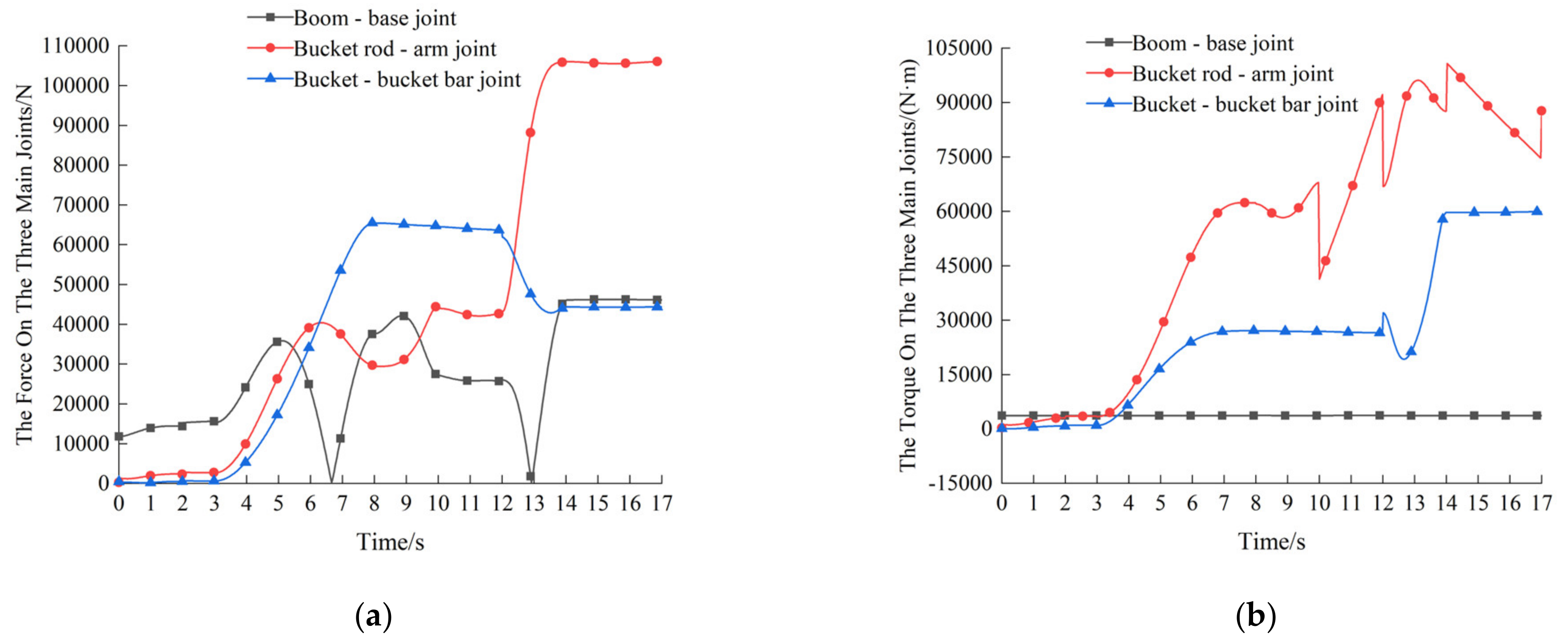
After the simulation, the dynamic load data at the three main joint friction subsets of the work unit were exported in ADAMS post-processing, as shown in Figure 2.
As can be seen from the Figure 2, 0–2 s for the preparation of digging stage, three joints friction force are small, mainly considering the impact of gravity of the working device itself; 3–8 s for the bucket digging stage, due to the tip of the teeth by the resistance to digging, the bucket joints force and torque increased dramatically, at this time, the friction of the joints end face collision effect is obvious; 8–10 s for the excavation of the full load of bucket rod lifting stage, the bucket rod joints force and moment In the obvious fluctuation, mainly considering the bucket full of material and the mechanical arm of its own gravity to bring the impact; 10–17 s for the base slewing and unloading stage, lifting to a certain height, the base slewing platform instantly start, due to the role of inertial force, will produce a large acceleration, at this time, the dynamic arm joints force changes are obvious, the bucket joints due to the bearing of gravity, the force is still increasing; with the completion of the unloading of buckets, the bucket with the completion of bucket unloading, the force on the bucket joint is decreasing, and only the effect brought by the weight of the robot arm itself is considered at this time.
3. Experimental Verification of the Dynamic Force of the Joint Friction Subsets of the Working Device
3.1. Experimental Principle and Equipment
In this experiment, the dynamic stress test was carried out at the specified position of the excavator working device by using a DH3818Y static strain tester (see Figure 3). The selected stress measurement sensor is a 120-3CA right-angle strain gauge rosette, the schematic diagram of which can be seen in Figure 4 [10], and the main instrument parameters of the experiment are shown in Table 3.
The experimental strain gauge measurement is based on the principle of the Wheatstone bridge, in which G is a tiny current meter. At the same time, there are four resistors, also called the four arms of the bridge, in which Rx resistors are connected to the strain gauge, as shown in Figure 5a. The resistance strain gauges are attached to the surface of the specimen, and the strain gauges are connected to the strain gauge in the 1/4 bridge way, as shown in Figure 5b. When no strain is generated, the Rx resistance does not change, the circuit bridge is balanced, and the current meter indicates 0. With the deformation of the strain gauge, the mechanical quantity is transformed into an electrical abundance by using the resistance effect, i.e., the resistance value of the wire changes after the deformation is generated by force along its axis direction, and the stress–strain can be measured by using this principle [11,12].
In this experiment, the working device was subjected to three major joint friction contact articulation areas: the bucket and bucket rod articulation friction, the bucket rod and moving arm articulation friction, and the moving arm and base rotation platform articulation friction. The three measurement areas were polished to a smooth metal surface to reduce the experimental error. After adjusting the experimental excavator to the working attitude, strain gauges were attached to the three main joint friction subassemblies. After the strain gauges were connected to the strain gauge and the program was adjusted, the experiment was started, as shown in Figure 6.
3.2. Comparison of Experimental Results and Simulation Results
The data measured from the three sets of strain gauges were averaged to reduce the experimental error. The corresponding equivalent force was calculated according to the fourth strength theory. In contrast, the dynamic load data from the dynamics simulation was imported into ABAQUS 2022 for analysis to obtain the equivalent force data corresponding to the dynamics simulation, as shown in Figure 7 [13].
As can be seen from Figure 7, through the software joint simulation and dynamic stress test experiments, the experimental value and simulation value are basically consistent; there is a small error range, and the main consideration of the actual excavation conditions is in the presence of machine operation errors, the occurrence of slight vibration, to verify the correctness of the idea of dynamic analysis. In order to further analyze the wear change process and wear mechanism of joint friction vice on the basis of dynamic load, this paper takes the three main joint friction vice of bucket joint end face friction vice, which is directly in contact with the excavated object as an example and analyzes the change of joint end face wear.
4. Analysis of Dynamic Wear Characteristics of the Endface Friction Pair
4.1. Bucket Joint Main Pin Model Establishment and Dynamic Wear Theory Analysis
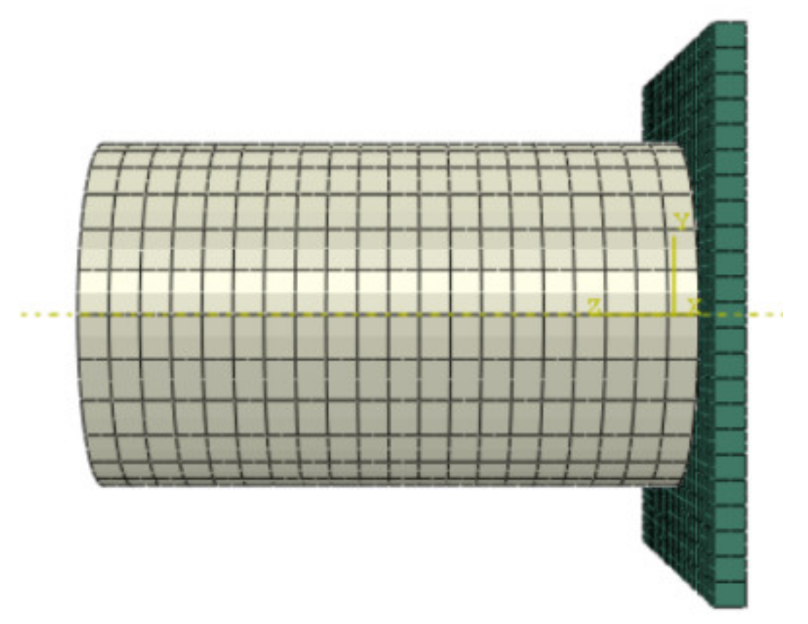
The mesh quality of the finite element model adopts hexahedral mesh, and the boundary condition is that the force of the friction pair of the bucket joint of the working device is consistent, and the overall structure of the excavator working device is relatively complex, so the friction pair of the bucket joint is intercepted in a ratio of 1:1 on the whole machine of the excavator working device, and the finite element model of the kingpin of the bucket joint is established, and the finite element software ABAQUS is imported into the finite element software ABAQUS for analysis after appropriate mold repair, as shown in Figure 8.
The central pin of the bucket joint is mainly composed of a sleeve, a hook, and left and right trunnions. The material properties of the simulation process are shown in Table 4, and face-to-face contact is set for the mutual communication of the model; a rotation constraint is charged at the center of the pin, which rotates together with the bucket as a whole.
Excavator work device operation process, bucket joint end friction sub-contract, contact collision instant momentum conservation, before and after the collision system kinetic energy is not conserved, the collision process by the average contact pressure and tangential friction, by the momentum theorem and the law of conservation of energy is obtained:
where are the mass of the sleeve and the ear plate. are velocity of the sleeve and ear plate before and after collision, respectively. is the normal contact force. is the relative sliding distance of contact surfaces.
The tangential friction converts into internal energy in emotional conflict, reflected in the material wear process and temperature change of the contact end-face. The tangential friction force is given by the following:
where is the tangential friction force.
Where , , , can be measured by relevant experimental data. The average contact pressure and tangential friction of the joint friction pair in the working device under active wear are obtained through the theoretical calculation of the momentum theorem and the law of conservation of energy, which provides the theoretical foundation for further analysis of contact wear in the joint friction pairs.
4.2. End-Face Friction Pair Dynamic Contact Stress Analysis
The dynamic load data at the bucket joint friction pair are imported as boundary conditions, and the dynamic contact stress peak cloud diagrams of the left and right end surfaces of the sleeve during excavation operation are obtained, as shown in Figure 9 and Figure 10.
A critical moment is taken for analysis in each of the three processes of the work device: the preparation digging stage, the digging material stage, and the unloading stage after the entire load. As can be seen from the cloud diagram, the work device starts to prepare for excavation from t = 6.8 s at rest; due to the influence of its gravity and the external environment, the operation process will produce a slight angle of tilt, resulting in the contact between the sleeve and the end face of the ear plate extrusion collision contact stress. At this time, the sleeve left and right end contact stress value is small. The working device is digging resistance to start the excavation process, and the bucket tooth tip and the excavated object are entirely in contact; at this time, the bucket on both sides of the load material gravity is not the same; the difference is more prominent. When t = 10.2 s, the base is in the uniform rotation stage, and the acceleration process has been completed; due to the instantaneous acceleration of the acceleration process to produce a significant acceleration brought about by the contact friction surface collision impact, the sleeve left and right end surfaces created the maximum contact stress value, the maximum contact stress on the left end surface of the sleeve is 37.35 MPa, and the maximum contact stress on the suitable end surface is 64.29 MPa. The contact stress values on both the left and right ends of the sleeve showed an increasing trend, and the area as a whole showed a circular distribution. When t = 14.45 s, the base decelerated to stop and finished discharging, the contact stress value on the left and right ends of the sleeve became smaller, and the overall contact stress value on the left and proper ends of the sleeve showed a trend of first increasing and then decreasing. The joint force curve corresponding to the top node of the contact stress value on the left and right ends of the collective bucket sleeve is derived, i.e., the standard contact pressure curve is shown in Figure 11.
Under this condition, the frictional contact of the bucket joint end face has significantly collided, and long-term exposure to this alternating load will lead to severe wear at one end face. In addition, the wear is not caused by a single operation but by high circumferential fatigue of the end face caused by long-term exposure to alternating loads. Therefore, the problem of end face wear needs to be further explored based on the dynamic standard contact stress–time curve combined with the relevant theory.
4.3. The Friction Pair Surface and Wear Simulation Analysis
The theoretical basis of the contact collision wear analysis of the excavator’s joints is based on the classical Archard wear model. The traditional Archard wear model considers that the material wear is related to the average load on the contact end-face, the relative slip, and the hardness of the material [14]. The Archard wear model is also being modified and improved with the continuous progress of research work.
The general expression of the Archard wear model is as follows:
where V is the wear volume. K is the wear coefficient of the material, W is the average load of the end-face, H is the hardness of the material.
Equation (6) divided by the contact area of Aa:
where Aa is the face-to-face contact area at the gap of the friction pair on the bucket joint end face, h is the value of wear depth, P is the contact pressure value for the method of two end faces.
The Archard wear model is used to discretize the time based on Equation (7), and the expression of the discretized wear depth is as follows:
Assume the total of m nodes on the end-face:
Finite element simulation of the contact wear of the bucket joint end face friction pair was carried out using the subroutine UMESHMOTION in the ABAQUS/Standard module, which is a subroutine for simulating the wear of a material using computer simulation techniques and predicts the wear of a material by simulating the interaction between the surfaces of the material and their mutual motions. The corresponding wear depth value [15,16] was solved through the ALE adaptive grid constraint subprogram UMESHMOTION, imported by the user-defined FORTRAN program. Wherein the ALE adaptive grid allows the independent movement of the grid when the material is severely deformed under stress and ensures the high quality of the grid at all times. Moreover, the ALE adaptive grid maintains the topological shape of the grid and ensures the quality of the grid.
The wear simulation requires high grid quality, especially in the complex model that needs the complex subprogram. Wear starts at the corner of the node unit, and ALE meshes need to be re-divided in a particular interval order by writing the FORTRAN program. Aiming at the characteristics of the main pin end face contact friction vice of the bucket joint of this model excavator, combined with the requirements of experimental analysis, the joint friction vice wear model with simplified mesh division is established as shown in Figure 12.
The quality of the mesh must meet high standards when performing wear simulations. In addition, as the complexity of the model increases, the writing of subroutines becomes more complex. Wear usually starts at the corners of nodes or cells, so when writing the program using the FORTRAN language, it is necessary to make sure that the cells and nodes in the ALE adaptive mesh redraw region are in order at certain intervals. By introducing the dynamic standard contact pressure curves of the left and right end faces in the above excavation conditions, the wear profile of the left and right end face lugs in one wear cycle is shown in Figure 13.
As seen from the Figure, in one wear cycle, the wear depth value of the right-end face trunnion is significantly larger than that of the left-end face. The wear area shows a more apparent ring-shaped area, and the wear depth value is more prominent in the room with a considerable contact stress value. The numerical simulation results show that the wear depth value of the right end face is significantly larger than that of the left front. With the increase in the wear cycle, the accumulation of the end face wear depth value will undoubtedly produce more severe wear. In addition, the end face wear is not caused by one operating condition. Still, it is caused by the long-term effect of the alternating load, so the increasing operation condition and operation time will undoubtedly lead to severe wear of the end face.
5. Friction Pair and Wear Experiments
Experimental verification of the wear change process of the left and right end surfaces at the friction subsets of the bucket joint end of the excavator work unit was carried out on an end face friction and wear tester. A square block specimen with a side length of 38 mm × 38 mm and material of 45 steel was machined by wire-cutting. The software that comes with the wear tester was used to derive the load change, relative sliding speed, friction coefficient, and temperature change during the wear process, and the experimental setup is shown in Figure 14. The upper specimen is 35 steel with Poisson’s ratio of 0.31 and modulus of elasticity of 212 GPa; the lower illustration is 45 steel with Poisson’s ratio of 0.3 and modulus of elasticity of 210 GPa; the experiments were carried out in a room temperature environment and under the condition of submerging the specimens in No. 46 hydraulic oil.
Before starting the experiment, the specimens were polished to prevent surface scratches and raised parts. The load of the wear tester was zeroed, and after installing the upper and lower representatives, the dynamic contact stress value curve at the left and right end surfaces of the bucket joint was set on the software that came with the wear tester and set to a loading load of 64.29 MPa. The wear time was 60 min, and the surface wear profile of the square block specimen was shown in Figure 15 after the end of wear.
It can be seen from Figure 15 that under normal contact pressure in 60 min, the end-face of the left and right ear plates wear seriously and present scratches, pits, and ripples. Additionally, the wear area presents annularly, and the wear depth of the right end-face is more significant than that of the left. It is found that the high wear depth is high contact stress located in the top area of the right end-face and the below site of the right end-face compared with the contact stress figure. The variation curve of friction coefficient during wear is derived as shown in Figure 16.
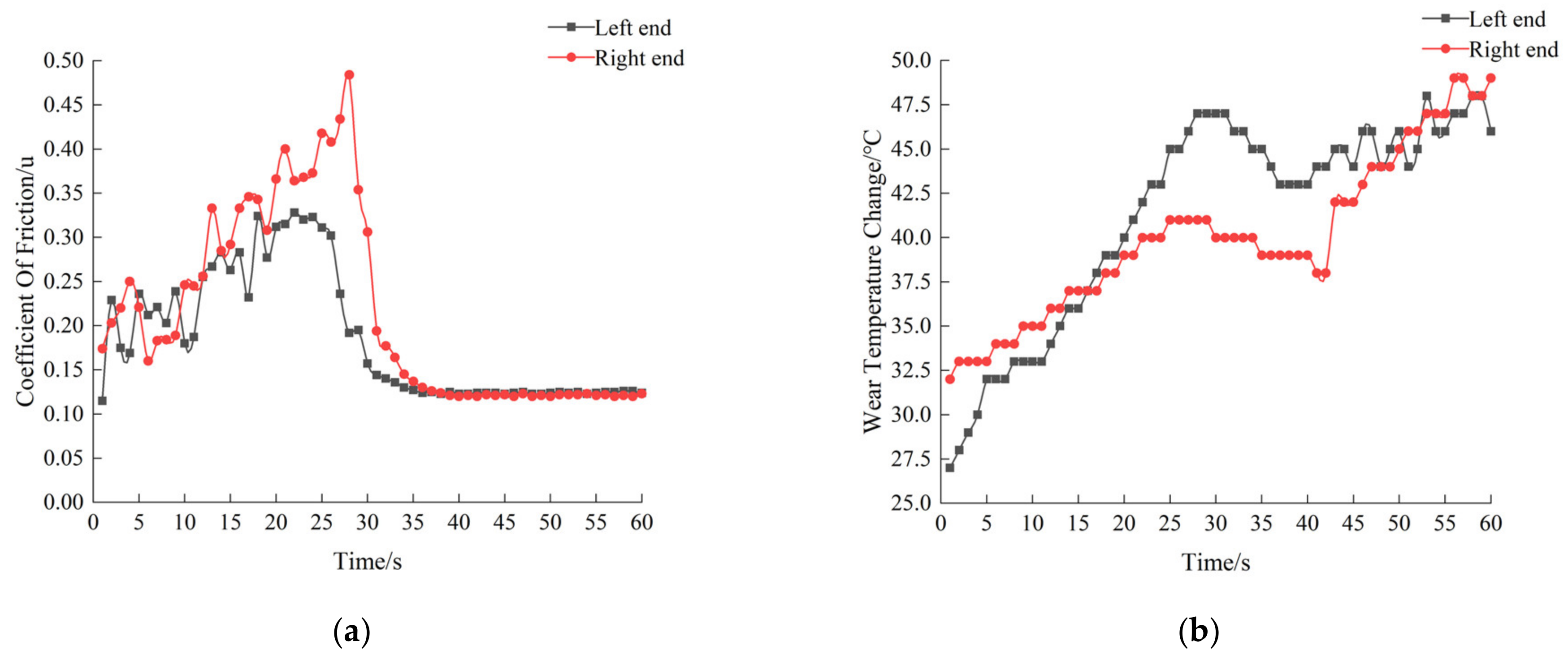
As can be seen from Figure 16, the friction coefficient of the left and right end surfaces at the beginning of the wear moment is a sharp increase in the phenomenon; the wear tester started from a standstill, by the surface roughness and the external environment, etc., at this time for the run-in wear stage; with the wear process continues, the friction coefficient gradually decreases, the wear becomes slow and progressively tends to stabilize 35 min later, and the wear rate is maintained in a stable range. In this process, the surface of the contacting friction pair produces a higher temperature during the wear process, and the temperature fluctuates wildly, which will accelerate the failure of the lubrication device on the surface of the specimen, making the wear faster and intensifying the degree of surface wear damage [17,18,19,20,21].
The left and right end face specimens were cut into circular specimens at the same position for the observation of wear morphology under the scanning electron microscope, and the surface morphology after the observation of wear under the scanning electron microscope is shown in Figure 17 and Figure 18.
The wear mechanism is mainly fatiguing wear under the action of dynamic contact pressure. As the wearing process continues, the surface scratches intensify. At the same time, due to the generation of a more significant number of granular particles, the wear mechanism is fatigue wear to abrasive wear. There are many deep plow grooves distributed parallel to the sliding direction on the wear surface, as well as tearing cracks caused by plastic deformation, and gradually abrasive wear is the main form of wear.
The metal material on the surface of area C of the right end face is also peeling off and generating large craters; at this time, the wear mechanism is manifested as fatigue wear under the action of stress cycles, the surface of the friction sub-produces tiny cracks and further expands in each cycle, eventually leading to fatigue fracture of the material; at the same time, as the wear continues, the surface of area D produces more obvious scratches and furrows. At this time, the wear mechanism is manifested as abrasive wear and constantly transformed from fatigue wear to the mechanism dominated by abrasive wear.
The metal material on the surface of area C of the right end face is also peeling off and generating large craters; at this time, the wear mechanism is manifested as fatigue wear under the action of stress cycles; the surface of the friction sub-produces tiny cracks and further expands in each process, eventually leading to fatigue fracture of the material; at the same time, as the wear continues, the surface of area D produces more obvious scratches and furrows, at this time the wear mechanism is manifested as abrasive wear, wear and constantly transformed from fatigue wear to the agency dominated by abrasive wear.
The material used at the friction side of the bucket joint end of the excavator work unit is 45 steel. EDS analysis was per formed on the elemental content changes generated on the wear surface of the specimen, and the essential distribution of the four wear surfaces in the areas of A, B, C, and D was analyzed by EDS Mapping. The central elemental distribution diagram is shown in Figure 19, and the main fundamental content is shown in Table 5.
After taking the specimens mentioned earlier for EDS elemental content analysis, it was found that the entire content of Fe decreased more compared with other areas, and the surface wear was more serious; the wear mechanism of area D was mainly abrasive wear. In area C, due to the production of large craters, the content of Fe and Mn elements decreased more during the transformation from fatigue wear to abrasive wear, and P elements gradually disappeared. In area A and area B, due to the surface material shedding less compared with other areas, the main elemental content of the worn specimens was relatively average.
In fact, the content of the C element in the specimens after wear is relatively high. C element can form the matrix organization and form a solid solution with Fe and Mn, etc., which increases the strength of the matrix and improves the wear resistance of alloying elements; Si element acts as a deoxidizer in the material and improves the wear resistance of alloying elements at the same time. Analysis of the effect of different element content in the specimen after wear on the friction wear effect of the material can provide a basis for the material composition in improving the design. Mainly, the addition of friction-reducing elements can refine the grain, make the material form a new hard phase inside, and make the friction surface generate a chemical reaction film to improve the friction reduction effect. At the same time, some friction-reducing alloy elements can penetrate into the mutual friction sub-surface and sub-surface, thus improving the grain boundary structure of the material surface, which has a good effect on surface friction reduction and wear resistance.
6. Conclusions
This paper takes a model of an excavator working device as an example, obtains dynamic load data at the three main joint friction subsets by selecting typical excavation working conditions, and verifies the rationality of kinetic analysis through strain gauge experiments. Then, it takes the typical bucket end contact friction subsets as an example, analyzes the wear changes on the left and right end surfaces under this working condition, and derives the mechanism of wear action and surface element content changes through experimental verification. The following conclusions are drawn:
- (1)
- Under this working condition, the three main joint friction contacts of the working device are subjected to more obvious dynamic fluctuations, resulting in obvious contact and collision; at the same time, the experimental test data of the strain gauges are basically consistent with the simulation results, proving the rationality of the dynamics analysis.
- (2)
- The left and right end surfaces of the bucket joint end friction pair are subjected to dynamic contact stresses of different sizes and scattered effects; the wear area on the surface of the trunnion plate shows a circular area as a whole, and the wear is greater in the area with large contact stress values, and the wear depth value on the right end surface is greater than that on the left end surface, and the experimental test results are consistent with the simulation results.
- (3)
- The microscopic morphology of the wear surface of the left and right end surfaces was observed under SEM, and combined with EDS analysis, the wear mechanism of the specimen surface after wear was mainly based on fatigue wear and abrasive wear, and the transition from fatigue wear to abrasive wear was carried out continuously, after which abrasive wear was the dominant form of wear.
- (4)
- This paper uses software simulation method and experimental test data comparison, and through the modified Archard wear model using discrete analysis thinking method to solve the contact surface wear depth value method, etc., can provide theoretical guidance for the analysis of other construction machinery joint friction vice wear process and how to optimize the design of joint friction vice in the wear process.
Author Contributions
L.Z. wrote the manuscript. X.C. and W.L. (Wei Li) designed the study. Z.W. and Z.Z. developed the methodology. W.L. (Wei Liu) and T.G. developed the methodology. All authors have read and agreed to the published version of the manuscript.
Funding
This work was supported by the National Natural Science Foundation of China (Grant No. 51875152), the Anhui Province College Excellent Young Talents Fund Project (Grant No. gxyq2020034), Anhui Province Key Research and Development Program Project (202004a05020066, 202104a05020049), Anhui Province University Outstanding Youth Research Project (Project Approval Number: 2022AH020025), and Key Research Project of Natural Science of Anhui Provincial Colleges and Universities (Project Approval Number: 2022AH050257).
Data Availability Statement
Data are contained within the article.
Acknowledgments
We thank all the authors for their joint efforts to complete the experiment.
Conflicts of Interest
Author Wei Li was employed by the company Hefei Bolin Advanced Materials Company Limited. The remaining authors declare that the research was conducted in the absence of any commercial or financial relationships that could be construed as a potential conflict of interest.
References
- Tekin, K.S. Design and Construction of Boundary Lubricated Bearing Test Rig and Wear Analysis in Earthmoving Machinery. Master’s Thesis, Middle East Technical University, Ankara, Turkey, 2010. [Google Scholar]
- Park, J.Y.; Yoo, W.S.; Park, H.W. Matching of flexible multibody dynamic simulation and experiment of a hydraulic excavator. Proc. ACMD 2004, 459–463. [Google Scholar]
- Smolnicki, T.; Derlukiewicz, D.; Stańco, M. Evaluation of load distribution in the superstructure rotation joint of single-bucket caterpillar excavators. Autom. Constr. 2008, 17, 218–223. [Google Scholar] [CrossRef]
- Wang, Y.C.; Pang, W.J.; Zhou, M. Research on Digging Performance of Backhoe Hydraulic Excavator. Adv. Mater. Res. 2013, 718, 1673–1676. [Google Scholar] [CrossRef]
- Meng, Q.-H. Typical Friction Pair Wear Excavator Control Technology Research and Application. Ph.D. Thesis, Huazhong University of Science and Technology, Wuhan, China, 2004. [Google Scholar]
- Yang, H. Large excavator forearm connection shaft pin abrasion reasons and improvement measure. Sci. Technol. Innov. Appl. 2014, 26, 104–105. [Google Scholar]
- Long, Y.; Zhao, J. ABAQUS contact analysis in applying pin shaft mining mobile arm fault disposal. Building 2012, 6, 82–83. [Google Scholar]
- Shi, H.S.; Wang, L.H.; Yang, Z.; Wang, P.C. Dynamics simulation analysis on hydraulic excavator working mechanism based on rigid-flexible coupled modeling. Adv. Mater. Res. 2014, 889, 459–462. [Google Scholar] [CrossRef]
- Xiao, C.; Zhang, G.; Deng, R. Based on ADAMS hydraulic excavator working equipment dynamic simulation analysis. Shao Yang Univ. J. (Nat. Sci. Ed.) 2016, 13, 89–94. [Google Scholar]
- Wang, Z. Analysis of End Face Contact Performance of Joint Friction Pair of Excavator Working Device Based on Rigid-Flexible Coupling Dynamic Analysis. Master’s Thesis, Anhui University of Architecture, Hefei, China, 2022. [Google Scholar]
- Wu, K. Strain gauge bridge arrangement and group method in engineering application. J. Hui Univ. Archit. 2019, 27, 1–6. [Google Scholar]
- Hang, J.; Tao, R.; Jiang, Z.; Zhu, F.; Lei, D. Choose different strain rosette on the result of principal stress test. J. Lab. Res. Explor. 2016, 35, 32–36. [Google Scholar]
- Giri, A.; Pandey, C.; Mahapatra, M.M.; Sharma, K.; Singh, P.K. On estimating error in measuring the residual stress by strain gauge rosette. Measurement 2015, 65, 41–49. [Google Scholar] [CrossRef]
- Gui, C. Archard’s wear design calculation model and its application. Lubr. Seal. 1990, 61, 12–21. [Google Scholar]
- Li, C.; He, J.; Du, Y.; Xiao, W.; Wang, Z. Based on Archard model of machine tool guideway wear model and finite element analysis. J. Mech. Eng. 2016, 52, 8. [Google Scholar]
- Xu, J. Extrusion Cylinder Wear Mechanism and Influence Factors of Research. Master’s Thesis, Chongqing University, Chongqing, China, 2019. [Google Scholar]
- Arjmandi, M.; Ramezani, M.; Giordano, M.; Schmid, S. Finite element modeling of sliding wear in three-dimensional woven textiles. Tribol. Int. 2017, 115, 452–460. [Google Scholar] [CrossRef]
- Prajapati, D.K.; Tiwari, M. 3D numerical wear model for determining the change in surface topography. Surf. Topogr. Metrol. Prop. 2018, 6, 045006. [Google Scholar] [CrossRef]
- Yu, H.; Zhang, L.; Fan, J.; Chen, Q.; Wen, D.; Zheng, W. Casing wear 3D surface topography restoration and mechanism analysis. J. Tribol. 2007, 27, 477–481. [Google Scholar]
- Wurth, S.; Mehlan, A.; Werner Theisen, S.S. Identification of micro wear mechanisms of a high-speed train friction pair employing a wear debris analysis. In Proceedings of the EuroBrake Conference, Dresden, Germany, 4–6 May 2015. [Google Scholar]
- Wang, X.; Liu, B.; Xiao, J.; Qu, J.; Ding, G.; Yang, Y. Before the slider friction and wear failure mechanism and morphology characteristics analysis. J. Surf. Technol. 2019, 48, 141–148. [Google Scholar]
Figure 1.
Excavator research model. (a) The prototype model of the excavator. (b) The working device of a virtual prototype model.
Figure 1.
Excavator research model. (a) The prototype model of the excavator. (b) The working device of a virtual prototype model.

Figure 2.
Three main joints under the dynamic load diagram. (a) By trying to three main joints. (b) Three central joint moment diagram.
Figure 2.
Three main joints under the dynamic load diagram. (a) By trying to three main joints. (b) Three central joint moment diagram.

Figure 3.
DH3181Y static strain tester. Non-English words in the image are Manufacturer Name: Jinan Jiuwang Instrument Co., Equipment purchasing, Jinan, China.
Figure 3.
DH3181Y static strain tester. Non-English words in the image are Manufacturer Name: Jinan Jiuwang Instrument Co., Equipment purchasing, Jinan, China.

Figure 4.
Selection of strain gauge rosette and arrangement. Non-English words in picture: Resistance Strain Gauge, Yiyang Qingshan District Electronics Co., Yiyang, China.
Figure 4.
Selection of strain gauge rosette and arrangement. Non-English words in picture: Resistance Strain Gauge, Yiyang Qingshan District Electronics Co., Yiyang, China.

Figure 5.
Measuring principle and connection mode. (a) Measurement circuit. (b) Quarter bridge circuit connection.
Figure 5.
Measuring principle and connection mode. (a) Measurement circuit. (b) Quarter bridge circuit connection.

Figure 6.
Experimental preparation process. (a) The strain gauge paste method. (b) The experiment preparation process.
Figure 6.
Experimental preparation process. (a) The strain gauge paste method. (b) The experiment preparation process.

Figure 7.
Three points experimental value and simulation value comparison results. (a) To measure strain gauge paste way. (b) The bucket rod and the movable arm hinged points. (c) Movable arm slewing platform and base hinged points.
Figure 7.
Three points experimental value and simulation value comparison results. (a) To measure strain gauge paste way. (b) The bucket rod and the movable arm hinged points. (c) Movable arm slewing platform and base hinged points.

Figure 8.
The bucket king pin joints and joint collision model of friction pair. 1—Hinge pin. 2—Sleeve end. 3—Ear plate.
Figure 8.
The bucket king pin joints and joint collision model of friction pair. 1—Hinge pin. 2—Sleeve end. 3—Ear plate.

Figure 9.
Cloud diagram of dynamic contact stress of left end-face sleeve. (Unit: MPa). (a) t = 6.8 s. (b) t = 10.2 s. (c) t = 14.45 s.
Figure 9.
Cloud diagram of dynamic contact stress of left end-face sleeve. (Unit: MPa). (a) t = 6.8 s. (b) t = 10.2 s. (c) t = 14.45 s.

Figure 10.
Cloud diagram of dynamic contact stress of right end-face sleeve. (Unit: MPa). (a) t = 6.8 s. (b) t = 10.2 s. (c) t = 14.45 s.
Figure 10.
Cloud diagram of dynamic contact stress of right end-face sleeve. (Unit: MPa). (a) t = 6.8 s. (b) t = 10.2 s. (c) t = 14.45 s.

Figure 11.
The resultant force curve generated by the maximum stress node. (a) Left end-face. (b) Right end-face.
Figure 11.
The resultant force curve generated by the maximum stress node. (a) Left end-face. (b) Right end-face.

Figure 12.
The wear model of bucket joint friction pair end-face.

Figure 13.
The depth values of the end-face in the ear plate time within a wear cycle. (Unit: mm). (a) The depth values of left end-face. (b) The depth values of right end-face.
Figure 13.
The depth values of the end-face in the ear plate time within a wear cycle. (Unit: mm). (a) The depth values of left end-face. (b) The depth values of right end-face.

Figure 14.
The HDM-20 end-face wear test machine.

Figure 15.
The square block sample of wear surface topography. (a) The left end-face. (b) The right end-face.
Figure 15.
The square block sample of wear surface topography. (a) The left end-face. (b) The right end-face.

Figure 16.
Coefficient of friction–time vs. temperature–time curves for wear processes. (a) The friction coefficient of the ear plate end face changes with time. (b) The temperature of the ear plate end face changes with time.
Figure 16.
Coefficient of friction–time vs. temperature–time curves for wear processes. (a) The friction coefficient of the ear plate end face changes with time. (b) The temperature of the ear plate end face changes with time.

Figure 17.
The wear surface morphology of left end-face. (a) Area A. (b) Area B.

Figure 18.
The wear surface morphology of the right end-face. (a) Area C. (b) Area D.

Figure 19.
The elements distribution of different regions. (a) Area A. (b) Area B. (c) Area C. (d) Area D.
Figure 19.
The elements distribution of different regions. (a) Area A. (b) Area B. (c) Area C. (d) Area D.


Table 1.
Working dimensions of three groups of hydraulic cylinders (unit: mm).
| Bucket Cylinder | Stick Cylinder | Boom Cylinder | |
|---|---|---|---|
| Model length | 1659 | 2784 | 1881 |
| Maximum elongation length | 2263 | 2875 | 2490 |
| Maximum shrinkage length | 1378 | 1700 | 1500 |
Table 2.
Settings of the excavating process.
| Time | Set Up the Excavating Process |
|---|---|
| 0–2 s | Work device of the bucket cylinder complete shrinkage, in its most prominent mining radius position, ready to start mining. |
| 3–8 s | Bucket rod oil cylinder and a movable arm oil cylinder lock, bucket cylinder power drive digging bucket process, after reaching full stop digging. |
| 8–10 s | The working device of the end of the bucket digging began to end up at a certain height. |
| 10–14 s | Base rotary platform by static start turning 90°, bucket digging bucket and discharge. |
| 14–17 s | Rotary bucket digging bucket after discharge, base platform according to the end of the original road return 90° mining process. |
Table 3.
Main instrument experiment.
| The Instrument | Project | The Numerical |
|---|---|---|
| The experiment machine | The quality of the machine/t | 1.2 |
| Movable arm length/m | 1.67 | |
| The bucket rod/m | 1.15 | |
| Bucket capacity/m3 | 0.045 | |
| Triaxial strain rosette 120-3CA | Resistance value/Ω | 120 |
| Base size/mm | 10.5 × 10.5 | |
| Wire grid size/mm | 3.0 × 2.0 | |
| The sensitivity | 2.0 | |
| DH3818Y Strain gauge | Sampling rate/Hz | 1/2/5 |
| PC Data collection terminal | / | / |
| The strain gauge connected to the dedicated line | Wire diameter/mm | 1.6 |
| Galvanized copper wire | 17 roots |
Table 4.
The material properties of bucket joint kingpin in simulation.
| Material | Modulus of Elasticity/MPa | Poisson Ratio | The Density of/(kg·m−3) | Yield Stress/MPa |
|---|---|---|---|---|
| 45 steel | 210,000 | 0.3 | 7850 | 345 |
Table 5.
After the area around the central abrasion and element weight percentage (unit: %).
| Fe | Mn | Cr | S | P | Si | C | |
|---|---|---|---|---|---|---|---|
| Area A | 88.17 | 0.48 | 0.12 | 0.10 | 0.10 | 0.29 | 10.74 |
| Area B | 87.11 | 0.55 | 0.17 | 0.17 | 0.03 | 0.24 | 11.72 |
| Area C | 84.44 | 0.27 | 0.21 | 0.32 | 0 | 0.22 | 14.54 |
| Area D | 73.81 | 0.38 | 0.11 | 0.15 | 0.32 | 0.19 | 25.05 |
Disclaimer/Publisher’s Note: The statements, opinions and data contained in all publications are solely those of the individual author(s) and contributor(s) and not of MDPI and/or the editor(s). MDPI and/or the editor(s) disclaim responsibility for any injury to people or property resulting from any ideas, methods, instructions or products referred to in the content. |
© 2024 by the authors. Licensee MDPI, Basel, Switzerland. This article is an open access article distributed under the terms and conditions of the Creative Commons Attribution (CC BY) license (https://creativecommons.org/licenses/by/4.0/).
Share and Cite
MDPI and ACS Style
Chen, X.; Zhang, L.; Li, W.; Wang, Z.; Zhang, Z.; Gao, T.; Liu, W. Analysis of Dynamic Wear Characteristics of Joint Contact Friction Pair of Excavators Working Device. Lubricants 2024, 12, 113. https://doi.org/10.3390/lubricants12040113
AMA Style
Chen X, Zhang L, Li W, Wang Z, Zhang Z, Gao T, Liu W. Analysis of Dynamic Wear Characteristics of Joint Contact Friction Pair of Excavators Working Device. Lubricants. 2024; 12(4):113. https://doi.org/10.3390/lubricants12040113
Chicago/Turabian StyleChen, Xuehui, Lei Zhang, Wei Li, Zijian Wang, Zhengbin Zhang, Ting Gao, and Wei Liu. 2024. "Analysis of Dynamic Wear Characteristics of Joint Contact Friction Pair of Excavators Working Device" Lubricants 12, no. 4: 113. https://doi.org/10.3390/lubricants12040113
Note that from the first issue of 2016, this journal uses article numbers instead of page numbers. See further details here.