Influence of Lubrication Status on Milling Performance of Bionic Micro-Textured Tools

School of Mechanical and Vehicle Engineering, Changchun University, Changchun 130022, China
*
Author to whom correspondence should be addressed.
Lubricants 2024, 12(4), 118; https://doi.org/10.3390/lubricants12040118
Submission received: 8 March 2024
/
Revised: 28 March 2024
/
Accepted: 1 April 2024
/
Published: 2 April 2024
(This article belongs to the Special Issue Friction and Wear of Alloys)
Abstract
:Titanium alloy material has physical properties such as low thermal conductivity, high hardness, and surface resilience, which are prone to problems such as large milling force, low machining efficiency, and poor surface quality in processed products during dry milling. This document details our process of isolating micro-textures from biological structures, applying them to cutting tool surfaces to create micro-texture milling cutters, and employing this micro-texture technique to reduce friction and prevent wear on these cutters. According to the milling dosage and the installation position between the tool and the workpiece, the effective working area of the cutting edge of the ball-end milling cutter is calculated. At the same time, a self-lubricating cutter was constructed by using a laser to process micro-textures and filling solid lubricant inside the micro-textures. An analysis was conducted to compare the milling efficiency of bionic microtextured cutters in both dry and micro-lubricated environments. It was found that the self-lubricating tool promoted a 3% to 5% decrease in milling force, a reduction in the coefficient of friction, a high surface finish of the machined workpiece, and an alleviation of chip sticking at the edge area.
1. Introduction
Titanium alloy materials with low density, high specific strength, good corrosion resistance, and fatigue resistance are widely used in the manufacturing industry, but these parts usually require high-precision machining [1,2,3]. Therefore, the production of titanium alloy parts faces challenges due to the characteristics of titanium alloy materials such as low thermal conductivity, chemical instability, etc. Milling chips gathered at the cutting edge are not easy to dissipate, resulting in a local temperature rise in the chip adhesion on the surface of the tool, which leads to tool wear and thus affects the machining quality of the product parts [4,5]. Therefore, the question of how to improve the machining efficiency of titanium alloys and develop efficient machining tools is a hot research issue nowadays. In recent times, with the deepening of tribology and bionics research, relevant scholars have found that, in order to adapt to the environment, organisms have evolved excellent friction and wear resistance, such as shark epidermis, dung beetle heads, and lotus leaf blades, etc. [6,7,8]. Relevant researchers and scholars have applied the above micro-textures extracted from biological epidermis to the surface of traditional machining tools, machined micro-textures in the working area of the tool, and utilized the micro-textures on the tool surface to change the friction state between the tool and the chips, thus enhancing the service life of the tool [9,10]. Therefore, the question of how to establish micro-texture on the surface of the tool in a reasonable manner is a study of practical significance.
S. Yang et al. designed a V-groove micro-texture structure on the tool surface based on the bionic principle and simulated the milling process of different V-groove micro-texture structure tools using simulation software. They also built a test platform to test the performance of the micro-texture structure milling cutter and found that the optimum milling performance of the tool is achieved when the V-groove micro-texture structure is opened at an angle of 79°. The slot spacing is 170 µm, the width is 30 µm, and the distance between the cutting edges is 90 µm. It was found that the milling performance of the cutter was optimized when the slot pitch was 170 µm, the width was 30 µm, and the edge distance was 90 µm [11]. J. Pan constructed linear flute and V-groove micro-texture structures on the tool surface and conducted milling tests. It was found that the V-groove micro-texture tool promoted the milling three-way force reduction by 9.27%, 21.98%, and 12.44%, respectively, and in addition, it was also found that the V-groove micro-texture tool improved the surface finish of the machined workpiece [12]. X. Tong calculated the theoretical tool–chip contact length during cutting based on the chip curl theory and combined it with the metal cutting theory and the mechanism of micro-texture action to obtain the theoretical tool–chip contact area, which provides a theoretical basis for the subsequent precise preparation of micro-texture on the tool surface [13]. Y. Zhang et al. proposed a method to reduce tool wear by designing micro-texture configurations on the tool surface. It was found that with the increase in the number of micro-texture configurations, the wear on the fore-aft face showed a tendency to decrease and then increase [14]. However, under dry-cutting conditions, due to the harsh machining conditions, the micro-textured tool can improve the friction state between the tool and chip during machining. However, machining without mechanical lubrication conditions is prone to tool wear. Cooling and lubrication are considered the main purposes of the extensive use of cutting fluids in machining because the ability to dissipate heat from the tool surface directly affects tool wear and service life. However, environmental awareness and production cost considerations have led to the choice to reduce the use of cutting fluids when machining component products [15,16]. Related studies have found that self-lubricating tools are constructed by filling solid lubricants into the micro-textured parts of the tool to improve the friction between the tool and the chip [17,18]. Z. Wu et al. fabricated a self-lubricating tool using surface weaving and comparatively analyzed the machining performance of the self-lubricating tool and the conventional tool in cutting titanium alloy materials. They found that the solid lubricant directly provides lubrication for the tool–chip contact surface during the cutting process, which promotes the dissipation of heat from the tool surface and prolongs the life of the tool [19]. Y. Xing et al. suggested the following. To address the problem of tool life shortening caused by dry-cutting conditions and intense friction on the tool surface, a self-lubricating coated tool was manufactured for cutting tests. It was found that the cutting force was reduced by 17.6% to 29.6%, and the coefficient of friction decreased by 8.8% to 11.7% compared to the conventional tool. MoS2 was observed to form a lubricating oil film on the tool surface, significantly reducing tool wear [20]. S. Wenlong et al. used a laser to create four pits of micro-texture on the front face of a carbide tool and filled them with solid lubricants of different materials for dry-cutting tests. The test results show that the cutting force and tool wear of self-lubricating tools are significantly reduced. At cutting speeds of less than 100 m/min, the MoS2 solid lubricant forms an oil film, promoting the most significant decrease in the coefficient of friction. This shows the practicality of self-lubricating tools and provides a cleaner machining process for cutting [21].
Subsequent to the aforementioned studies, it becomes evident that earlier research predominantly concentrates on enhancing tool efficiency through micro-textures, rarely addressing bionics, the origins of these micro-textures, and their mechanisms of action. This document presents a model of a biological body’s micro-texture, mirroring a tool’s surface micro-texture. The micro-texture’s structure is replicated on the tool’s surface, leading to the creation of a micro-texture milling cutter and the filling of the micro-texture with a solid lubricant in the micro-texture zone, aiming to explore how lubrication conditions and milling variables affect milling efficiency. Considering the quantity of milling and the micro-texture’s mechanism of action, we initially propose design principles for positioning the micro-texture on the ball end milling cutter, followed by computing its effective working area at the cutting edge. Next, the micro-texture undergoes laser processing on the tool’s surface, followed by the execution of the milling test to evaluate the micro-texture tool’s efficacy. Ultimately, the creation of a self-lubricating instrument involved infusing solid lubricant into the bionic micro-texture for the milling examination, followed by a comparative analysis of the tool’s milling efficiency in this lubricated condition, aiming to realize the development of a highly efficient cemented carbide ball end milling cutter.
2. Theoretical Analyses
As the tool surface is subjected to high temperature and high pressure for a long time, the friction between the contact surfaces continues to act on the cutting edge part of the tool, which can easily cause damage to the tool surface. In the milling process, the carbide tool is always in close contact with the cutting layer of the workpiece material. The cutting layer of the workpiece fractures due to external load, forming chips. The local temperature of the tool surface rises, and the chips formed easily adhere to the tool surface, leading to a reduction in the tool’s service life [22,23,24].
2.1. Analysis of Friction Reduction and Anti-Wear Mechanism of Micro-Texture
In the microscopic state, the contact of two objects is regarded as the contact between two point peaks. In the cutting process, the tool and the workpiece apply external load through the machine tool to produce relative motion, resulting in increasing contact points and contact area. The surface material undergoes plastic deformation in the contact area, while the internal material experiences elastic deformation. During processing, when the stress value on the contact surface reaches the material’s yield limit, the material exhibits a fracture phenomenon [25,26]. The contact diagram of the two objects in the microscopic state is shown in Figure 1.
Therefore, the actual contact area between the tool and the workpiece can be expressed as Equation (1):
where —load on the contact surface; —extruded yield pole of the contact material; and —actual contact area.
The friction generated during the metal-cutting process is shown in Equation (2):
where —friction and —shear strength.
Therefore, the coefficient of friction in the contact region of the surface of the friction pair can be expressed as Equation (3):
where —coefficient of friction.
Therefore, the calculated coefficient of friction between the contact surfaces of two objects can be expressed as Equation (4):
It can be seen from Equation (4) that the coefficient of friction in the peak contact area between the tool and the workpiece can be expressed as the ratio of the shear strength to the extruded yield limit of the material. This shows that this coefficient of friction is a constant. From Equations (1) and (2), it can be seen that by constructing micro-texture structures in the area of close contact between the tool and the workpiece, the direct contact area between the tool and the workpiece is reduced, thus changing the friction state.
The micro-textured tool–chip contact length is equal to the real contact length (LS) minus the total width of the micro-texture on the tool surface (n × M). Therefore, the micro-textured tool–chip real contact length can be expressed as Equation (5).
where L—true contact length of micro-texture tool; LS—actual cutting length; n—number of micro-textures; and M—micro-texture width.
So the actual contact area of the micro-texture tool with the workpiece is Equation (6):
where W—cutting width.
The actual friction is expressed as (7):
From Equation (7), it can be seen that the reasonable placement of micro-textures in the close contact area between the tool and the workpiece can effectively reduce the actual contact area between the tool and chip, change the friction state of the tool surface, and reduce the generation of cutting force. At the same time, the surface micro-texture structure shows good storage capacity, making it easy to capture the tiny chips retained on the surface of the cutter during milling, thus avoiding the abrasive wear of the tool surface. The contact between the micro-textured tool and the chip is shown in Figure 2.
2.2. Effective Position Distribution of Micro-Texture Structure of Carbide Ball End Milling Cutter
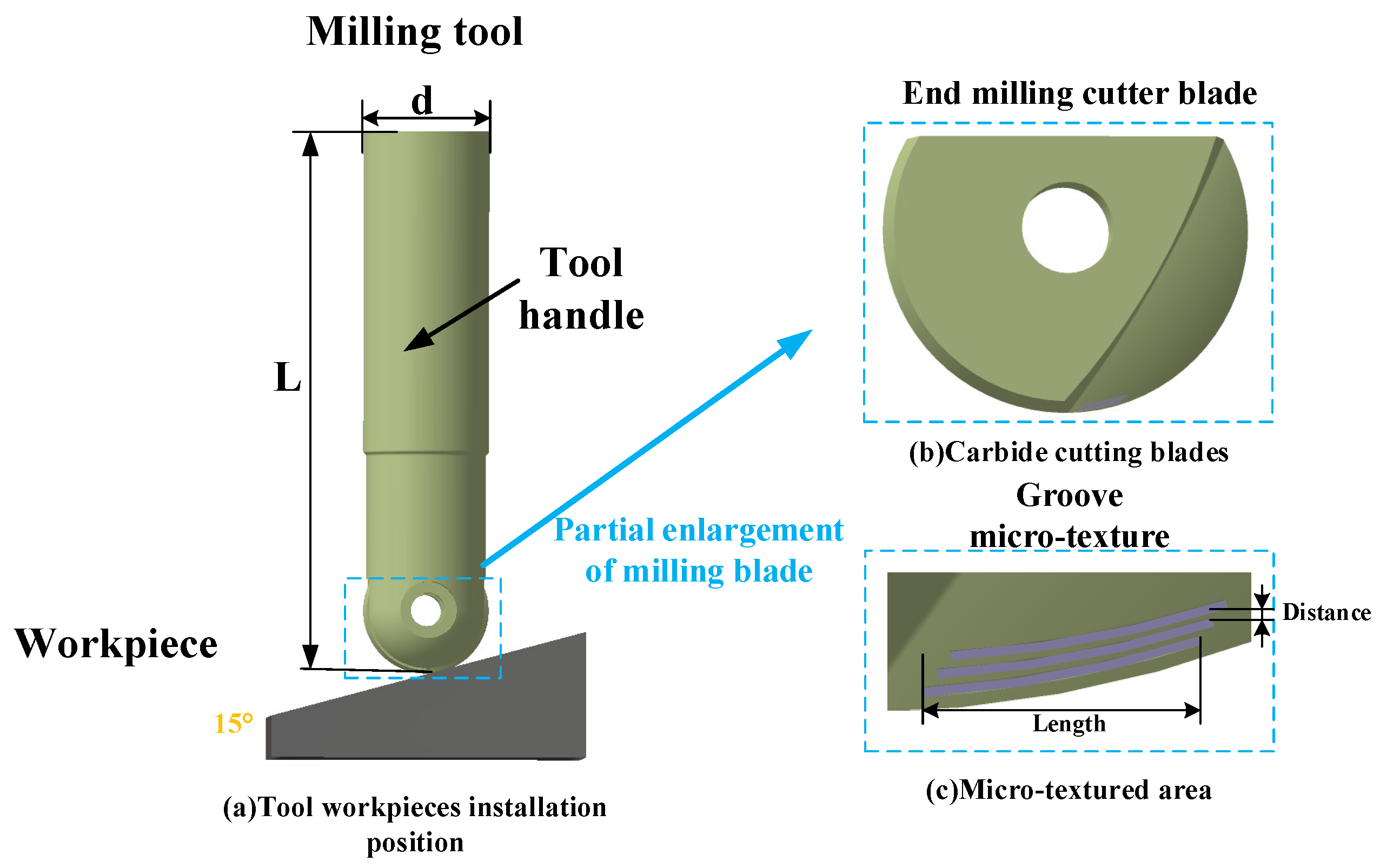
In general, a complete milling motion consists of a rotary motion of the tool, which is held on the spindle, and a linear motion of the workpiece, which is held in a fixture. When milling starts, the main working area of the tool is the front face of the cutter, so the friction is mainly concentrated on the milling cutter surface [27,28,29]. Therefore, to place the micro-texture structure on the front face of the milling cutter, the first step is to determine the effective working area of the tool. The carbide ball end milling cutter installation position is shown in Figure 3.
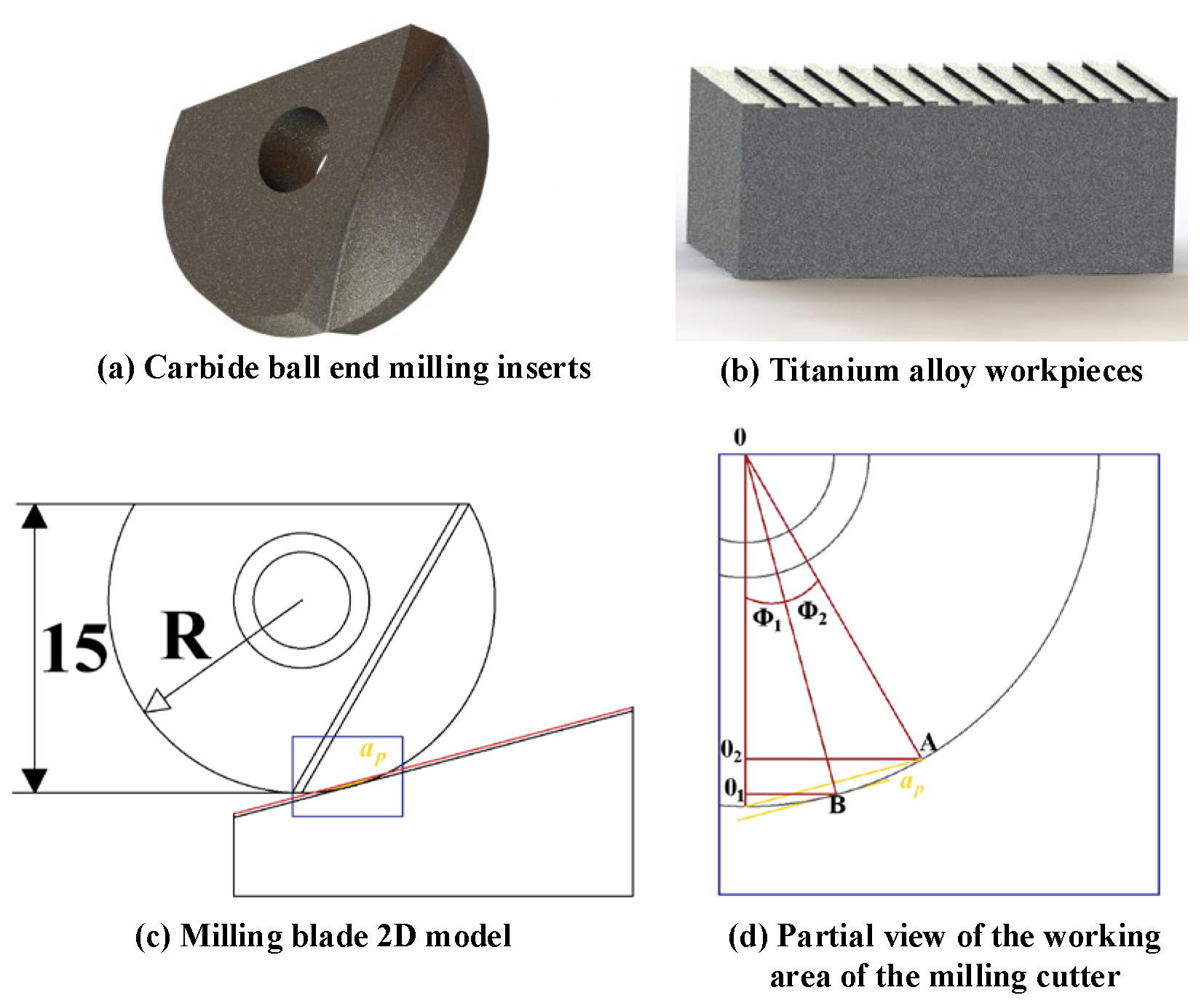
In the milling test, it was found that when the feed per tooth is far fz less than the cutting radius R of the tool, the milling area of the tool is related to the angle between the workpiece and the tool, the depth of milling, and the size of the milling blade radius. Figure 4 shows the tool and workpiece plane angle of 15°, ap for the milling depth, θ for the tilt angle, R for the milling blade radius, O2A for the maximum milling length, O1A for the minimum milling length, and milling area for O1O2AB.
The maximum milling length O2A, the milling depth ap, and the inclination angle between the tool and the workpiece can be calculated as the maximum milling area and the minimum milling area because the workpiece and the tool are perpendicular to each other, i.e., the angle O1OB is 15°, the Φ1, Φ2-angle can be known through the geometrical calculation:
So the maximum milling radius O2A of the ball end milling cutter is shown by Equation (10):
The minimum milling radius O1B is shown by Equation (11):
The radius of the milling cutter selected in this paper is 10 mm, and the initial milling depth is 0.5 mm. Therefore, the maximum milling lengths for O2A = 5.475 mm and O1B = 2.588 mm can be obtained by Equations (10) and (11). As a result, ABO1O2 represents the maximum micro-texture structure distribution area.
2.3. Self-Lubricating Tool Action Mechanism
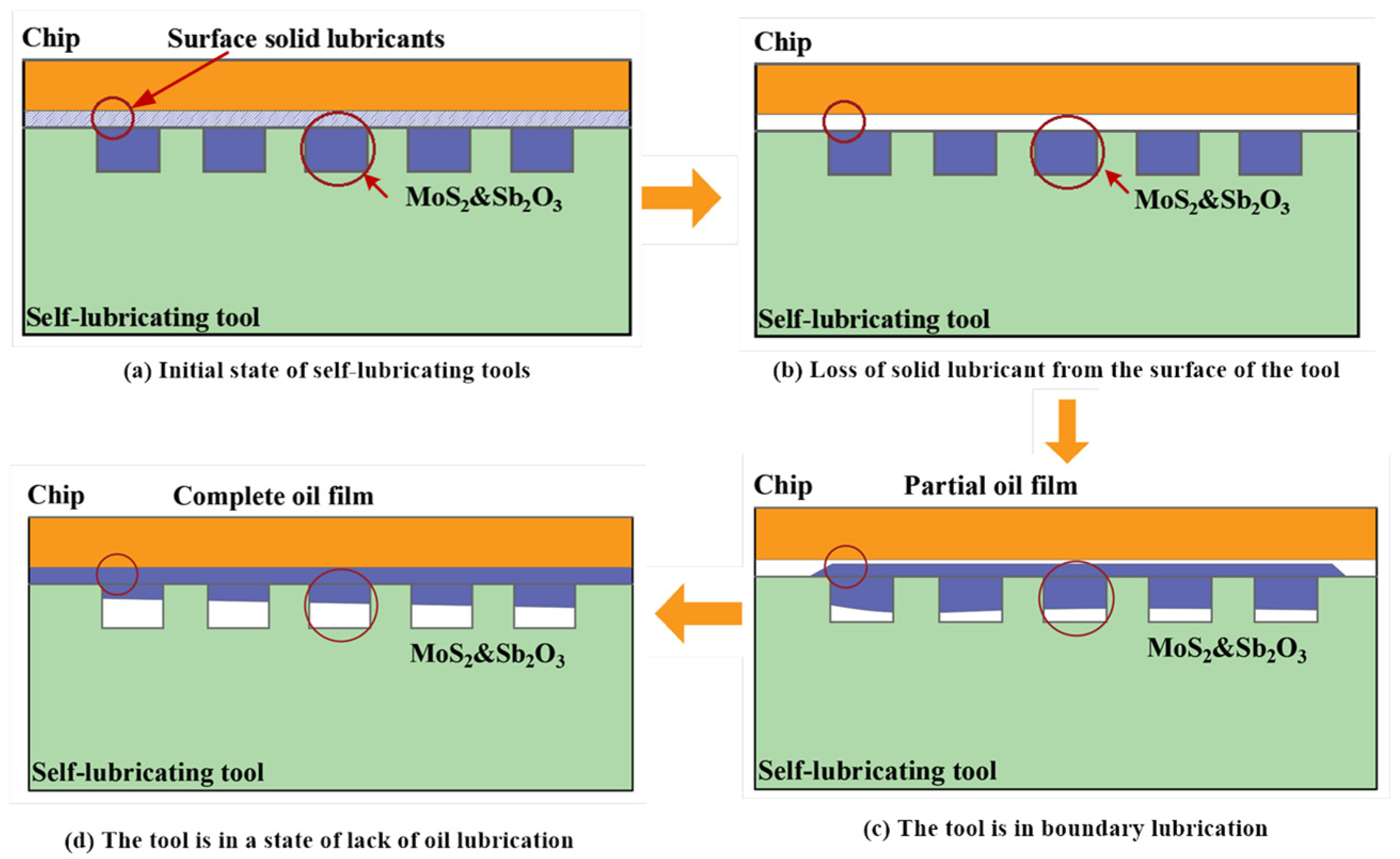
Self-lubricating tools refer to a new type of cutting tool that does not require additional lubricants to be added during the milling process and relies on the tool itself to lubricate and reduce friction [30,31,32]. At present, self-lubricating tools mainly achieve their self-lubricating behavior through the tool matrix and high-temperature-resistant solid lubricant. In this paper, a self-lubricating tool with solid lubricant added to the matrix is used. In the research conducted on micro-textured tools, it was found that the surface micro-texture showed good storage capacity on the tool surface, so solid lubricant was filled in the micro-textured part. During the milling process, the solid lubricant stored in the micro-textured part overflows to relieve friction on the tool surface and reduce milling force and temperature. Figure 5 shows the schematic diagram of the working process of the self-lubricating tool.
Before milling starts, the well-proportioned solid lubricant is filled inside the groove micro-texture, and due to the good bonding ability of the solid lubricant with the carbide cutter body, a layer of solid lubricant particles will be covered on the surface of the cutter, as shown in Figure 5a. At the beginning of cutting, the solid lubricant on the surface of the tool is in direct contact with the workpiece material. With the rapid rotation of the tool, the solid lubricant, which fails to form an oil film in time, is gradually lost as the cutting proceeds, as shown in Figure 5b. In the continuous cutting state, the tool surface is in a high-temperature and high-pressure state for a long time. The local temperature of the tool surface increases, resulting in extrusion and thermal expansion. The solid lubricant inside the micro-texture groove will be extruded, leading to a lack of oil lubrication for the tool, as shown in Figure 5c. As the chip continues to flow out along the tool surface, the tool and the workpiece’s close contact area form an oil film due to the chip’s drag dressing on the tool surface. At this time, the lubrication area on the tool surface increases, and the tool is in a state of boundary lubrication, as shown in Figure 5d. It can be seen that the solid lubricant can cover the tool surface well, and with cutting, the lubrication state shifts from dry friction to a lack of oil lubrication and eventually becomes a boundary lubrication state, improving the friction characteristics of the tool surface. In addition, the use of solid lubrication materials usually results in low shear strength. When the tool surface is covered by solid lubrication, the shear strength of the tool surface decreases. Although it is difficult to form a complete lubricant film during high-speed rotation in cutting compared to the dry friction state, under boundary lubrication conditions, friction can be reduced.
2.4. Trench Microweave Sources
Shells are the outer shells of mollusks living at the water’s edge, and their surface calcareous material has excellent properties such as toughness and strength. It is observed that the shell surface has prominent woven structures with two adjacent prominent weaves in an irregular convex ridge and groove structure, and the arrangement, size, and morphology of the weave structures affect the hardness and impact resistance of the surface calcareous material of the shell [33,34], as shown in Figure 6. The grooved micro-texture structure was extracted based on the surface morphology of the shells for the tool surface. Figure 6a shows a surface morphology of the shell, Figure 6b shows a localized enlarged view of the surface structure of the shell, and Figure 6c shows the measurement of the surface topography to obtain the height profile of the shell surface.
3. Micro-Texture Milling Test
3.1. Preparation of Bionic Groove Micro-Texture Ball End Milling Cutter
Currently, the commonly used methods for processing tool micro-textures are photolithography, EDM, and machining. Laser processing methods have the advantages of high energy density, good processing controllability, fast processing speed, and easy realization of precision processing. Laser processing is the use of high-energy density laser beams on the material for processing. Through the photothermal effect and other effects, the material surface produces high-temperature melting and impact, thus achieving the goal of processing. In this study, we chose the laser machining technique to create micro-textured gaps of 150 μm, 200 μm, and 250 μm on the tool’s surface and on the micro-textured ball end milling cutters, labeled W1, W2, and W3, as depicted in Figure 7. Table 1 displays the parameters for micro-textured dimensions.
After laser processing of the milling cutter’s surface, residual debris will be present on and surrounding it. The laser process produces significant heat, leading to debris accumulating and sticking to the tool’s surface, which impacts the precision of milling tests and experiments. Consequently, cleaning the micro-textured tools after processing, inserting the laser-processed blade into an ultrasonic machine, and letting ultrasonic waves travel through the solution is essential, leading to simultaneous vibrations in both the cleaning tank and the cleaning agent, which helps eliminate residues within the micro-texture. Post-cleaning, assess the milling cutter’s micro-texture depth as depicted in Figure 8.
3.2. Milling Test Materials and Equipment
The test was conducted using machined material for the domestic grade of TC4 titanium alloy (Ti6Al4V). The workpiece specifications were a 90 mm × 50 mm × 20 mm rectangular block, and the workpiece was mounted on the machine fixture. The tool is a carbide ball end milling cutter blade, with insert model BNM-200 and cutter shank model 20R10-200L. The cutter shank length is 200 mm. The test bench is shown in Figure 9. The milling test of the titanium alloy was carried out using the test method of controlling variables. The milling tests of the conventional milling cutter and micro-texturing milling cutter were carried out under dry and micro-lubricated conditions. The milling parameters used in the test are shown in Table 2.
3.3. Influence of Lubrication Conditions on Milling Performance of Bionic Micro-Texture Structure Ball End Milling Cutter
3.3.1. Effect of Lubrication Conditions on Milling Forces
Milling force is one of the criteria for evaluating the milling performance of micro-textile tools, which can intuitively respond to the intensity of the extrusion and friction between the tool and the chip in the milling process. Therefore, this paper integrates micro-texturing with solid lubricant to deeply investigate the influence of the lubrication state on the milling force. Figure 10 shows the effects of conventional tools and three kinds of micro-textured ball end milling cutters on the milling force under dry and micro-lubrication states. From Figure 10a, it can be seen that under the same milling speed, the milling force gradually decreases with the increase in micro-texture spacing. When the same milling cutter is used for machining, the milling force gradually increases with the increase in milling speed. When the W3 cutter was used for processing at a milling speed of 2500 r/min, compared with the conventional cutters W1 and W2, the W3 cutter promoted a decrease in milling force by 41.23%, 9.68%, and 3.27%. The change in milling speed is one of the reasons for the change in milling force. Due to the increase in milling speed, the workpiece material is subjected to increased shear force per unit of time, and the deformation of the workpiece material increases, leading to an increase in milling force. For the ball end milling cutter blade with different micro-texture spacing, as the micro-texture spacing increases, the number of effective micro-textures in the working area of the milling cutter blade increases, and the milling performance is enhanced.
A comparative analysis of Figure 10a,b shows that the three self-lubricating condition tools promote a 3–5% decrease in milling force. This is due to the fact that when milling with conventional tools, the tool surface is in a dry, non-lubricated state, resulting in difficulty dissipating heat and debris from the tool surface over time, leading to an increase in milling force. For a self-lubricating milling cutter, due to the groove structure of the micro-texture pattern on the tool surface, the chip and the tool surface cannot be in complete contact with each other, increasing the air exchange space on the tool surface, reducing the contact area between the tool and the chip, which contributes to the decline in milling force. At the same time, due to the presence of solid lubricant in the micro-texture, the phenomenon of tiny chips sticking to the surface of the tool is weakened, resulting in a decrease in the length of chip bonding on the tool surface. So, the self-lubricating tool is conducive to reducing milling force. Additionally, the chips stay on the tool surface, and under high-speed rotation, the solid lubricant in the micro-texturing parts is dragged onto the tool surface to form an oil film, further promoting the decrease in shear strength on the contact surface between the tool and chip. Through the extrusion of solid lubricant within the micro-texture structure, the tool surface transitions from a state of oil deficiency to one of boundary lubrication, thereby reducing friction on the tool surface and achieving self-lubrication of the micro-texture structure tool.
3.3.2. Effect of Lubrication Conditions on the Coefficient of Friction
During the process of cutting metal, significant friction exists between the chip and the tool, with the interaction between the cutter’s surface and the chip being particularly intricate. This complexity impacts the creation of the chip, the material deformation of the workpiece, and the magnitude of the milling force. Numerous types of micro-texture exist on the surface, and the varying extent of this micro-texture directly influences the friction properties of the milling cutter’s surface.
An equation can demonstrate the mean coefficient of friction µ for the surface of the tool [35]:
where —tool front angle; Fy—y direction milling force; and Fz—z direction milling force.
By taking the milling forces obtained from the above milling test into Formula (12), different surface friction coefficients of micro-textured milling cutters are calculated, as shown in Figure 11. From Figure 11a, it can be seen that with the increase in milling speed, the friction coefficient in dry and micro-lubricated conditions both show an increasing trend. Figure 11b shows that when the milling speed is the same, the lubrication state directly affects the friction coefficient on the milling cutter surface. Compared to dry milling, self-lubricating milling cutters W1, W2, and W3 respectively promote a decrease in surface friction coefficient by 2.78%, 8.12%, and 3.03%. This is because the lubricant filled in the micro-structured areas on the milling cutter surface with MoS2/Sb2O3 mixture exhibits a good synergistic effect between the components at high milling speeds, leading to a decrease in friction coefficient. Under experimental conditions, the friction between the hard alloy micro-structured tool and titanium alloy workpiece belongs to sliding friction, and the stress on the friction pair is very high. The contact surface is prone to tool wear under long-term high temperature and pressure cycles. As the milling progresses, solid lubrication is continuously squeezed out, forming good lubrication conditions on the tool surface, which helps reduce the friction coefficient.
3.3.3. Effect of Lubrication Conditions on Surface Roughness
This study employs the WYKO N9100 optical profiler to assess the surface texture of the machined components, as the roughness of these parts significantly influences their longevity. When assessing the workpiece’s surface roughness, Ra denotes the specific area’s surface, encompassing both the height value and the deviation’s reference height, with the Ra value of the smoother surface being smaller. This metric is typically employed to appraise the machined components’ surface quality in Ra processing. Upon finalizing the milling process, the workpiece surface undergoes data collection post-processing with identical cutter mark parameters and with a uniform cutter mark measurement of three, and its mean value is computed as the test data, including the count of micro-weave structures on the workpiece surface’s roughness, as depicted in the influence diagram in 12. Figure 12 shows the effect of micro-textured tools on the surface roughness of the workpiece under different lubrication states. In Figure 12a, it can be seen that the value of surface roughness increases with the increase in milling speed. The surface of the conventional tool does not add lubricant, unlike the micro-textured and self-lubricating tools. The conventional tool produces excessively high surface roughness at all milling speeds. In the case of micro-textured tools, the friction state changes due to the action of surface micro-textures, leading to a reduction in milling force and surface roughness. The performance of micro-textured tools is further improved with the increase in micro-texture spacing. Comparing (a) and (b) in Figure 12, it can be found that at a milling speed of 3500 r/min compared with the dry cutting condition, the W1, W2, and W3 self-lubricating tools promote the surface roughness reduction by 1.13%, 1.54%, and 1.18%, respectively; at a milling speed of 3000 r/min comparing with the dry cutting condition, the W1, W2, and W3 self-lubricating tools promote the surface W1, W2, and W3 self-lubricating tools promote the reduction of surface roughness by 2.463%, 4.24%, and 2.68% respectively at a milling speed of 2500 r/min compared to the dry cutting condition; W1, W2, and W3 self-lubricating tools promote the reduction of surface roughness by 2.48%, 3.45%, and 11.76% respectively at a milling speed of 2500 r/min compared to the dry cutting condition.
This is due to the dry-cutting tool not containing any lubricating elements. In a relatively low thermal conductivity and high strain state, it affects the formation of chips, forcing them to fracture in the shear region of the cutting layer of the workpiece. This results in discontinuous, irregular chips and increasing instability in milling processing, which leads to a decline in the surface roughness value of the workpiece material after processing. With the milling process, a large number of chips accumulate on the tool surface. The milling temperature rises, and the chip material adheres or welds to the tool surface. With the increase in processing time, the chips gradually accumulate on the milling edge, ultimately leading to contact between the chips and the processed surface. As a result, the surface roughness increases.
Figure 13 shows the surface morphology of the workpiece after machining with self-lubricating tools at different micro-texture spacings. The surface of the machined titanium alloy sample was observed using an optical profilometer microscope. From Figure 13a, it can be observed that the workpiece material produces defects, which are due to the short interaction time between the self-lubricating tool and the workpiece. Compared with the lower milling speed, only part of the solid lubricant is able to form a film of oil at higher milling speeds, which leads to an increase in the milling force, and the surface roughness of the workpiece rises after machining. Figure 13c shows the surface morphology of the workpiece after machining with a self-lubricating tool with 250 µm micro-texture spacing, which has very good surface quality compared to the workpiece surface machined by other tools. As milling proceeds for self-lubricating tools, the solid lubricant in the micro-texture structure is extruded to form an oil film. The tool surface has good lubrication, promoting the flow of chips along the tool surface to avoid chip accumulation. At the same time, it reduces the coefficient of friction on the tool surface, leading to a decrease in milling force. The surface roughness of the workpiece material decreases after machining.
3.3.4. Effect of Lubrication Conditions on Tool Wear
The study utilized an ultra-deep field microscope to examine the configuration of the milling cutter and chips post-machining. Figure 14 shows the tool wear of ball end milling cutters with different lubrication conditions under the same milling conditions. From the figure, it can be observed that the traditional tool surface exhibits a chip adhesion phenomenon, and tool wear is more serious. The W1 micro-texture structure tool, in the dry cutting state, alleviates the phenomenon of chip adhesion to the tool’s surface. However, a small amount of debris adheres to the edge of the milling cutter blade parts. The self-lubricating W1 micro-texture structure tool significantly improves the issue of chip adhesion to the tool’s surface.
For the carbide micro-texture structure ball end milling cutter, the surface wear process of the tool can be divided into three stages: At the beginning of the milling show for sliding friction and under the action of surface pressure, a small amount of debris by the micro-texture structure part of the capture, and storage in the micro-texture structure inside the cutter surface in the role of shear stress, produces a small amount of cracks. In the second stage, with the milling process, the chip accumulation inside the micro-texture, in the repeated cycle of contact stress under the action of the friction sub-surface cracks gradually to the internal expansion of the tool, when the value of the material’s shear stress reaches the maximum, at this time, the deformation of the tool surface, the role of the external load, the micro-textures near the material organization changes, at the same time, a large number of tiny debris was squeezed into the micro-texture inside the micro-texture, with the milling process, the groove micro-texture is gradually filled. As the milling process continues to advance, the micro-texture gradually fills up. In the third stage, the filled micro-texture parts undergo milling at high temperature and pressure for an extended period. Under the influence of high pressure, it is very easy to cause stress concentration phenomena on the surface of the tool. The tool surface micro-textures gradually expand, increasing tool wear. For self-lubricating tools, the micro-textured tool surface undergoes prolonged extrusion during continuous milling. The local temperature of the tool edge part rises, causing the solid lubricant to gradually extrude out of the micro-texture part due to thermal expansion. This forms an oil film in the close contact area between the tool and the chip, providing good lubrication to the tool surface. Simultaneously, it reduces friction on the tool surface, alleviating wear and prolonging tool service life.
Figure 15 shows the morphology of the chips of the self-lubricating W1 tool at different milling speeds. It can be seen that with the increase in milling speed when milling titanium alloy, the chips change from crumbling chips to curled chips. In milling, the workpiece material undergoes deformation, fracture, and chip formation. The chips flow out, taking away most of the milling heat. Only the smaller-sized chips are easily captured by the micro-texture structure of the tool and the chip contact area. When the milling speed is higher, the deformation of the cutting layer of the workpiece material per unit time increases, accelerating the chip-forming speed. The chips break and overflow after curling. Due to the small thermal conductivity and low elastic modulus of titanium alloy material, it easily accumulates on the tool surface, causing damage to the tool surface.
After the comparative analysis of the milling performance of micro-textured tools in dry and micro-lubricated conditions, it can be seen that the self-lubricating tools show better cutting performance in both high- and low-speed milling. This promotes the reduction in the milling force, coefficient of friction, and surface roughness of the workpiece after machining. It is also found that the milling performance is significantly enhanced with the increase in the area occupied by the micro-texture in the cutting edge part of the ball end milling cutter.
4. Conclusions
Aiming at the carbide ball end milling cutter, milling titanium alloy is prone to milling force, insert local temperature rise, chip adhesion in the cutting edge parts of the tool, resulting in the processing of the workpiece surface quality reduction, and other issues. This paper designs and uses laser processing to create a micro-texture structure ball end milling cutter in the dry and micro-lubrication state for the milling test. The study found the following:
- With the increase in micro-texture spacing, the micro-texture in the cutting-edge part of the tool occupies a larger area, significantly enhancing the milling performance of the milling cutter. At the same time, the surface micro-texture reduces friction on the tool surface, increases the space for heat exchange on the tool surface, and prolongs the service life of the tool.
- Experiments with self-lubricating tool milling reveal a stark difference from the micro-textured tool’s dry cutting condition, where the self-lubricating tool’s milling force was reduced by 3% to 5%. Post-machining, the workpiece’s surface precision dropped to 0.973 μm, and there was a notable decrease in the friction coefficient. Additionally, it was observed that applying a 250 μm pitch to the self-lubricating micro-textured ball milling cutter markedly mitigated the softening effect of the chip sticking cutter, preventing the chip from adhering to the cutter’s surface.
- In the process of using a self-lubricating milling cutter with a 250 μm pitch for machining, there was a gradual shift in chip shapes from chipped to curled as the milling speed accelerated.
Author Contributions
H.S. data collection, data analysis, literature retrieval; C.M. writing manuscripts, charting, data collection.; B.W. document retrieval, data collection, research design; Q.L. experimental design, data collection. All authors have read and agreed to the published version of the manuscript.
Funding
Here we need to thank the following organizations for their strong support “Natural Science Foundation of Jilin Province-General Project, Study on the Machinability of Milling Titanium Alloy with Micro-texture Milling Cutter” (20220101227JC).
Data Availability Statement
Data will be made available on request.
Acknowledgments
The authors would like to thank the members of the project team for their dedication and efforts, and the teachers and schools for their help.
Conflicts of Interest
The authors declare no conflicts of interest.
References
- Yip, W.S.; To, S.; Zhou, H. Current status, challenges and opportunities of sustainable ultra-precision manufacturing. J. Intell. Manuf. 2022, 33, 2193–2205. [Google Scholar] [CrossRef]
- Bergs, T.; Holst, C.; Gupta, P.; Augspurger, T. Digital image processing with deep learning for automated cutting tool wear detection. Procedia Manuf. 2020, 48, 947–958. [Google Scholar] [CrossRef]
- Schultheiss, F.; Zhou, J.; Gröntoft, E.; Ståhl, J.E. Sustainable machining through increasing the cutting tool utilization. J. Clean. Prod. 2013, 59, 298–307. [Google Scholar] [CrossRef]
- Veiga, C.; Davim, J.P.; Loureiro, A.J.R. Review on machinability of titanium alloys: The process perspective. Rev. Adv. Mater. Sci 2013, 34, 148–164. [Google Scholar]
- Duan, R.; Deng, J.; Lei, S.; Ge, D.; Liu, Y.; Li, X. Effect of derivative cutting on machining performance of micro textured tools. J. Manuf. Process. 2019, 45, 544–556. [Google Scholar] [CrossRef]
- Yan, S.; Li, B.; Hong, J. Bionic design and verification of high-precision machine tool structures. Int. J. Adv. Manuf. Technol. 2015, 81, 73–85. [Google Scholar] [CrossRef]
- Yu, H.; Han, Z.; Zhang, J.; Zhang, S. Bionic design of tools in cutting: Reducing adhesion, abrasion or friction. Wear 2021, 482, 203955. [Google Scholar] [CrossRef]
- Ma, J.; Zhang, M.; Liu, Q.; Liu, X.; Yue, C.; Yang, S. A review of the research progress of bionic cutting tools. J. Mech. Eng. 2022, 58, 261–281. [Google Scholar]
- Arulkirubakaran, D.; Senthilkumar, V.; Kumawat, V. Effect of micro-textured tools on machining of Ti–6Al–4V alloy: An experimental and numerical approach. Int. J. Refract. Met. Hard Mater. 2016, 54, 165–177. [Google Scholar] [CrossRef]
- Yang, S.; Wang, Z.; Zhang, Y.; Wang, Q.; Cui, X.; Xie, Y. Finite element simulation of machining titanium alloy by micro-weave configuration ball end milling cutter. J. Shenyang Univ. Technol. 2015, 37, 530–535. [Google Scholar]
- Yang, S.; Guo, C.; Ren, W. Research on optimization of milling performance of V-groove micro-texture ball-end milling cutter. J. Mech. Sci. Technol. 2022, 36, 2849–2860. [Google Scholar] [CrossRef]
- Pan, J.; Ni, J.; He, L.; Cui, Z.; Feng, K. Influence of micro-structured milling cutter on the milling load and surface roughness of 6061 aluminum alloy. Int. J. Adv. Manuf. Technol. 2020, 110, 3201–3208. [Google Scholar] [CrossRef]
- Tong, X.; Zhang, Y.; Shen, J.; Qu, Q.; Han, P. Design of surface micro texture in the cutter-chip contact area of a cemented carbide cutter. Proc. Inst. Mech. Eng. Part B J. Eng. Manuf. 2023, 237, 1497–1508. [Google Scholar] [CrossRef]
- Zhang, Y.; Ji, H. Wear optimization of titanium alloy cutter milled with microtextured ball-end milling cutter. Adv. Mech. Eng. 2020, 12, 1687814019892102. [Google Scholar] [CrossRef]
- Yan, P.; Rong, Y.; Wang, G. The effect of cutting fluids applied in metal cutting process. Proc. Inst. Mech. Eng. Part B J. Eng. Manuf. 2016, 230, 19–37. [Google Scholar] [CrossRef]
- Debnath, S.; Reddy, M.M.; Yi, Q.S. Environmental friendly cutting fluids and cooling techniques in machining: A review. J. Clean. Prod. 2014, 83, 33–47. [Google Scholar] [CrossRef]
- Akhtar, S.S. A critical review on self-lubricating ceramic-composite cutting tools. Ceram. Int. 2021, 47, 20745–20767. [Google Scholar] [CrossRef]
- Ze, W.; Jianxin, D.; Yang, C.; Youqiang, X.; Jun, Z. Performance of the self-lubricating textured tools in dry cutting of Ti-6Al-4V. Int. J. Adv. Manuf. Technol. 2012, 62, 943–951. [Google Scholar] [CrossRef]
- Wu, Z.; Deng, J.; Su, C.; Luo, C.; Xia, D. Performance of the micro-texture self-lubricating and pulsating heat pipe self-cooling tools in dry cutting process. Int. J. Refract. Met. Hard Mater. 2014, 45, 238–248. [Google Scholar] [CrossRef]
- Xing, Y.; Luo, C.; Zhu, M.; Zhao, Y.; Ehmann, K.; Wu, Z.; Liu, L. Assessment of self-lubricating coated cutting tools fabricated by laser additive manufacturing technology for friction-reduction. J. Mater. Process. Technol. 2023, 318, 118010. [Google Scholar] [CrossRef]
- Wenlong, S.; Jianxin, D.; Ze, W.; Hui, Z.; Pei, Y.; Jun, Z.; Xing, A. Cutting performance of cemented-carbides-based self-lubricated tool embedded with different solid lubricants. Int. J. Adv. Manuf. Technol. 2011, 52, 477–485. [Google Scholar] [CrossRef]
- Khani, S.; Razfar, M.R.; Haghighi, S.S.; Farahnakian, M. Optimization of microtextured tools parameters in thread turning process of aluminum 7075 aerospace alloy. Mater. Manuf. Process. 2020, 35, 1330–1338. [Google Scholar] [CrossRef]
- Patel, D.S.; Jain, V.K.; Shrivastava, A.; Ramkumar, J. Electrochemical micro texturing on flat and curved surfaces: Simulation and experiments. Int. J. Adv. Manuf. Technol. 2019, 100, 1269–1286. [Google Scholar] [CrossRef]
- Elias, J.V.; Venkatesh, N.P.; Lawrence, K.D.; Mathew, J. Tool texturing for micro-turning applications–an approach using mechanical micro indentation. Mater. Manuf. Process. 2021, 36, 84–93. [Google Scholar] [CrossRef]
- Xu, T.; Ma, C.; Shi, H.; Xiao, K.; Liu, J.; Li, Q. Effect of Composite Bionic Micro-Texture on Cutting Performance of Tools. Lubricants 2024, 12, 4. [Google Scholar] [CrossRef]
- Kümmel, J.; Braun, D.; Gibmeier, J.; Schneider, J.; Greiner, C.; Schulze, V.; Wanner, A. Study on micro texturing of uncoated cemented carbide cutting tools for wear improvement and built-up edge stabilisation. J. Mater. Process. Technol. 2015, 215, 62–70. [Google Scholar] [CrossRef]
- Wang, D.; Yin, H.; Feng, L. Study on the effect of micro-texture coating tool on the milling quality of wood surface. Lubr. Sci. 2024. [Google Scholar] [CrossRef]
- Sun, Y.; Jin, L.; Gong, Y.; Qi, Y.; Zhang, H.; Su, Z.; Sun, K. Experimental Investigation on Machinability of Aluminum Alloy during Dry Micro Cutting Process Using Helical Micro End Mills with Micro Textures. Materials 2020, 13, 4664. [Google Scholar] [CrossRef] [PubMed]
- Pratap, T.; Patra, K. Mechanical micro-texturing of Ti-6Al-4V surfaces for improved wettability and bio-tribological performances. Surf. Coat. Technol. 2018, 349, 71–81. [Google Scholar] [CrossRef]
- Xing, Y.; Deng, J.; Wu, Z.; Liu, L.; Huang, P.; Jiao, A. Analysis of tool-chip interface characteristics of self-lubricating tools with nanotextures and WS 2/Zr coatings in dry cutting. Int. J. Adv. Manuf. Technol. 2018, 97, 1637–1647. [Google Scholar] [CrossRef]
- Song, W.; Deng, J.; Zhang, H.; Yan, P.; Zhao, J.; Ai, X. Performance of a cemented carbide self-lubricating tool embedded with MoS2 solid lubricants in dry machining. J. Manuf. Process. 2011, 13, 8–15. [Google Scholar]
- Torres, H.; Podgornik, B.; Jovičević-Klug, M.; Ripoll, M.R. Compatibility of graphite, hBN and graphene with self-lubricating coatings and tool steel for high temperature aluminium forming. Wear 2022, 490, 204187. [Google Scholar] [CrossRef]
- Jia, H. Strong Woven Research on Three-Dimensional Graphene Oxide-Based Biomimetic Shell Pearl Layer Block Material. Master’s Thesis, Taiyuan University of Technology, Taiyuan, China, 2020. [Google Scholar]
- You, C.; Xie, C.; Chu, X.; Zhou, W.; Zhao, G.; Lian, Y. Cutting performance of bionic cutting tools based on surface microstructures of blood clam Tegillarca granosa in dry cutting of CFRP. Int. J. Adv. Manuf. Technol. 2022, 119, 2961–2969. [Google Scholar] [CrossRef]
- Long, Y. Preparation of MoS2 Based Composite Solid Lubricant Micro-Weave Self-Lubricating Tool and Its Cutting Performance. Master’s Thesis, Xiangtan University, Xiangtan, China, 2014. [Google Scholar]
Figure 1.
Contact diagram of two objects in microscopic state.

Figure 2.
Micro-texture structure tool–chip contact diagram.

Figure 3.
Carbide ball end milling cutter installation position.

Figure 4.
Geometry of the milling process.

Figure 5.
Self-lubricating tool working process.

Figure 6.
Shell surface morphology.

Figure 7.
3 Micro-textured spacing.

Figure 8.
Depth of micro-texture.

Figure 9.
Milling test bed.

Figure 10.
Effect of lubrication status on milling force. (a) Influence of micro-textured tools on milling forces under dry cutting conditions. (b) Influence of micro-textured tools on milling forces under micro-lubrication conditions. (c) Decrease in milling force of 3500 r/min microtextured milling cutter compared to conventional.

Figure 11.
The effect of lubrication state on surface friction milling. (a) Relationship between friction coefficient and milling speed. (b) 3500 r/min milling cutter surface friction coefficient.
Figure 11.
The effect of lubrication state on surface friction milling. (a) Relationship between friction coefficient and milling speed. (b) 3500 r/min milling cutter surface friction coefficient.

Figure 12.
Influence of lubrication state on surface roughness of workpiece after machining. (a) Effect of microtextured tools on surface roughness under dry cutting conditions. (b) Influence of microtextured tools on surface roughness under micro-lubrication.
Figure 12.
Influence of lubrication state on surface roughness of workpiece after machining. (a) Effect of microtextured tools on surface roughness under dry cutting conditions. (b) Influence of microtextured tools on surface roughness under micro-lubrication.

Figure 13.
Surface morphology of workpiece after self−lubricating tool machining.

Figure 14.
Tool wear.

Figure 15.
Chip morphology of self-lubricating W1 tool at different milling speeds.


Table 1.
Micro-texture size parameters.
| Dimensional Parameters | Numerical Value (μm) |
|---|---|
| Spacing | 150, 200, 250 |
| Length | 1200 |
| Widths | 60 |
| Depth | 60 |
Table 2.
Milling parameters for milling tests.
| Parameters | Numerical Value |
|---|---|
| n (r/min) | 2500, 3000, 3500 |
| f (mm/z) | 0.1 |
| ap (mm) | 0.5 |
Disclaimer/Publisher’s Note: The statements, opinions and data contained in all publications are solely those of the individual author(s) and contributor(s) and not of MDPI and/or the editor(s). MDPI and/or the editor(s) disclaim responsibility for any injury to people or property resulting from any ideas, methods, instructions or products referred to in the content. |
© 2024 by the authors. Licensee MDPI, Basel, Switzerland. This article is an open access article distributed under the terms and conditions of the Creative Commons Attribution (CC BY) license (https://creativecommons.org/licenses/by/4.0/).
Share and Cite
MDPI and ACS Style
Shi, H.; Ma, C.; Wang, B.; Li, Q. Influence of Lubrication Status on Milling Performance of Bionic Micro-Textured Tools. Lubricants 2024, 12, 118. https://doi.org/10.3390/lubricants12040118
AMA Style
Shi H, Ma C, Wang B, Li Q. Influence of Lubrication Status on Milling Performance of Bionic Micro-Textured Tools. Lubricants. 2024; 12(4):118. https://doi.org/10.3390/lubricants12040118
Chicago/Turabian StyleShi, Hu, Chunlu Ma, Baizhong Wang, and Qinghua Li. 2024. "Influence of Lubrication Status on Milling Performance of Bionic Micro-Textured Tools" Lubricants 12, no. 4: 118. https://doi.org/10.3390/lubricants12040118
Note that from the first issue of 2016, this journal uses article numbers instead of page numbers. See further details here.