Physics of the Sub-Monolayer Lubricant in the Head-Disk Interface

Emeritus Professor of Tokyo Institute of Technology, Tokyo 152-8550, Japan
Lubricants 2024, 12(4), 117; https://doi.org/10.3390/lubricants12040117
Submission received: 17 February 2024
/
Revised: 19 March 2024
/
Accepted: 29 March 2024
/
Published: 31 March 2024
Abstract
:This review presents a series of studies which have demonstrated that the diffusion characteristics of rarefied mobile lubricant films used in modern magnetic disks can be evaluated by a novel diffusion theory based on continuum mechanics, and that the meniscus force of the rarefied film is the major interaction force at the head-disk interface. The limitations of the conventional diffusion and disjoining pressure equations are first shown, and diffusion and disjoining pressure equations for rarefied liquid films are proposed, showing that the diffusion coefficient is in good agreement with the experiment. The experiment, in which glass spheres with radii of 1 and 2 mm collided with magnetic disks of different film thicknesses, showed that attraction similar to the pull-off forces of a static meniscus was measured only at the separation. Furthermore, mathematical analysis of the elastic meniscus contact between a sphere and a plane with a submonolayer liquid film showed that the maximum adhesion force is equal to the meniscus pull-off force and that the contact characteristics become similar to those of the JKR theory as the liquid film thickness decreases. A basic physical model of submonolayer liquid film is also proposed to justify the continuum mathematical equations.
1. Introduction
Figure 1 shows a schematic diagram of a head slider that is flying on the surface of a rotating magnetic disk medium with a gap as small as 1 nm using the hydrodynamic air bearing principle. There are two types of slider dimensions: the smallest femto-slider is in the form of a minute block with length, width and height of 0.85, 0.45 and 0.23 mm respectively. The so-called pemto-slider, on the other hand, inherits the length of the pico-slider used in the previous generation (length 1.25 mm, width 1.0 mm) with relatively high air film stiffness in the pitch mode. The bearing surface of the slider has a complex groove based on the step bearing principle, and a magnetic transducer for recording and reproducing is formed on the bearing surface at the rear end center of the slider surface, where the flying clearance is minimized, using thin film lamination technology. A resistive element is formed in the area indicated by the red circle in Figure 1. During recording and playback, the head element is heated by electrical power and the head surface is forced to protrude by thermal expansion, locally creating a minute gap of about 1 nm or less. This on-demand reduction in head clearance can achieve a high recording density with high reliability by suppressing surface forces between solid surfaces and through lubricants, which will be discussed later. This on-demand head clearance control technology is called thermal fly-height control (TFC) or dynamic fly-height control (DFC) [1]. In addition, since around 2011, a micro coil called an embedded contact sensor (ECS) has been fabricated between the TFC heater and the head surface to detect the temperature of the head surface. The ECS is capable of monitoring surface contact conditions on the disk media surface, such as the temperature rise due to air friction and contact heat between the head and disk surface as well as the temperature rise due to the TFC heater, and the temperature drop due to local defects in the media [2].
In order to increase the magnetic recording density, it is important to reduce the clearance between the head and the recording medium. Around the year 2000, the need arose to reduce the flying height from the conventional 10 nm to 5 nm or less. However, a problem arose in the conventional pico-slider, where the slider exhibited self-excited vibration in the pitch mode due to the frictional force caused by the lubricating film [3]. In the pico-slider with another air bearing design, the negative stiffness of the adhesive force due to the van der Waals force between the head slider and the disk was more dominant than the stiffness of the air bearing force, causing the slider to become unstable [4].
By significantly reducing the attractive forces between the head and the disk by reducing the proximity surface area, TFC technology has made it possible to achieve stable flying conditions up to approximately 1 nm fly height. Increasing the lubricant bonding ability ratio and minimizing the mobile layer contributed to reduce lubricant transfer to head surface [5] and to stabilize the lubricant induced self-excited vibration of the slider. TFC technology also made it possible to eliminate fly height variations caused by manufacturing and adjustment variations of each head slider. In other words, for each head slider, the head surface position could be set constant from the disk contact state by managing the amount of back-off power to the TFC heater. As a result, the recording density of the latest disks has a circumferential bit pitch of 10 nm and a track pitch of 50 nm, allowing 1.2 TB to be stored on one side of a 90 mm diameter disk.
In Figure 1, the natural frequency of the slider, which consists of the stiffness of the air bearing film and the mass and moment of inertia of the slider, must be high enough for the head slider to follow the waviness and vibration of the rotating disk surface and to maintain a constant 1 nm clearance with a variation of less than 10%. Nowadays, the natural frequency of the slider has been increased to more than 350 kHz by optimizing the air bearing structure of the slider, and the high-frequency component of the microscopic waviness has become extremely small due to improvements in the accuracy of the disk surface machining technology. As a result, flying height fluctuations due to resonance in the pitch, translation and roll modes of the slider bearings have become negligible. However, when the surface clearance is reduced to less than 1 nm, the effective natural frequency of the slider decreases due to the surface adhesion, even in TFC sliders, and low-frequency runout of disk surface induces the clearance fluctuations. To clarify this phenomenon, it is important to evaluate the surface force between the head and the disk. The surface force between the head and the disk surface is related to the asperities and roughness of the disk surface, the surface force characteristics of the perfluoro-poly-alkyl ether (PFPE) lubricant film and the asperity meniscus characteristics. Because the TFC head must contact the magnetic disk surface to calibrate the flying clearance, it is important to elucidate the relationship between the touchdown behaviors and the surface force due to lubricant film and surface morphology in sub-nanometer scale.
As basic knowledge, the surface morphology of the disk are briefly explained, as it relates to the surface forces between the head and disk and to the friction and wear characteristics during contact. The surface roughness of the aluminum alloy or glass platter substrate is extremely small, similar to that of a silicon wafer. The magnetic medium formed on it has a shape in which independent perpendicular magnetic particles with diameters of 8–10 nm are separated by a thin boundary wall of SiO2. A diamond-like carbon (DLC) protective film with a thickness of 2~3 nm is formed on top of this, and a monolayer of PFPE lubricant is coated on top. A typical example of PFPE lubricant is Z-tetraol, whose surface energy at a film thickness of 1 nm is γd = ~15 mJ/m2 for the dispersive component and γp = ~10 mJ/m2 for the polar component. Since the surface energy of the lubricant is lower than that of DLC (γDLC = ~55 mJ/m2) [6], a lubricant has the effect of preventing contaminants such as peripheral substances and H2O from adhering to the disk surface and reducing the surface attraction force. However, when the head approaches about 1 nm or less, the surface forces of the head surface tend to cause the lubricant film to become unstable and to transfer to the head surface, causing meniscus bridge [5,7,8]. To overcome this problem, PFPE lubricants such as Demnum-4OH (D-4OH) have been developed with a strong bond to the disk surface and higher backbone stiffness [5]. Today, about 85% of the film is a bonded layer and about 15% is a mobile layer that provides a fluid lubrication function when the head makes contact with the disk.
Figure 2 is an example of AFM images of a 500 MB/platter magnetic disk surface around 2015 before and after lubricant coating in an area of 250 nm × 250 nm. The shape of the DLC and lubricant coated surface is dominated by that of the magnetic particles. The asperity density is around 5000 μm−2 with roughness (standard deviation) Sa = 0.22 nm (0.021 nm), Sq = 0.28 nm (0.026 nm) and maximum peak height = 1.24 nm (0.10 nm). The average peak height of the asperities and the depth of the pits are approximately 0.5 nm (0.17 nm) [9]. As can be seen from Figure 2, with lubricant, the pit depth becomes shallower and the radius of curvature of the pits becomes larger as the lubricant molecules fill the valley bottom and the radius of curvature of the asperities also increases slightly. As the total lubricant thickness is about 1~1.8 nm, it is thicker to fill the valleys between the asperities and the thin lubricant molecular chains are assumed to cover the DLC surface on the asperity surfaces [6]. The equivalent radius of curvature of the asperities, which is related to the asperity contact and surface forces, is about 15 nm [9].
In Section 2, the author describes his experimental and theoretical studies to develop a novel diffusion flow theory for rarefied liquid films with an average thickness of less than a single molecular layer, in which he has been involved for the last 10 years. Section 3 describes experimental and theoretical studies on meniscus forces, which are the main factor in head-disk interfacial forces, are described. Although the review will also refer to the related work by other researchers, the selection and understanding may be biased from the author’s point of view.
2. Diffusion Characteristics of Sub-Nanometer Lubricant Film
When the flying clearance of the TFC slider is reduced to 1 nm or less, the probability of asperity contact with the disk surface increases, and the wear reliability of the head surface due to contact becomes a serious problem. For this reason, the replenishment characteristics of the depleted grooves caused by head contact have been one of the most important research topics since the 2010s. Nowadays, about 85% of the bonded component of the lubricant film has a stress-relieving effect during the asperity contact between the head and disk, and about 15% of the mobile component has a fluid lubrication effect to reduce the friction coefficient.
The one-dimensional x-directional diffusion equation of a lubricating film with an average thickness h for more than a monolayer can be expressed in terms of the pressure p in the film and the film thickness h by following basic equation for Poiseuille flow.
where μ is the viscosity of the liquid film. The pressure p is expressed by Equation (2) using the ambient pressure pa, the disjoining pressure Π and the Laplace pressure pL, where Π and pL are given by (3) and (4), respectively.
where A is the Hamaker constant and corresponds to the intermolecular attraction coefficient between DLC or a solidified lubricant film chemically bonded to DLC and a mobile liquid film, d0 is the van der Waals distance between the solid film molecules and the mobile lubricant molecules, and γ is the surface energy of the lubricant. When analyzing the replenishment characteristics of depleted groove caused by the contact of the head slider with the disk surface, pa = 0 and the Laplace pressure due to surface tension is generally negligible compared to the disjoining pressure. Substituting Equations (2) and (3) into Equation (1), the basic equation for diffusion flow becomes
Research on diffusion and dewetting phenomena in multilayer liquid films up to the mid-1990s is described in reviews by de Gennes [10] and Oron [11]. Research on diffusion in mobile layers below one or two molecular layers of magnetic disks began with Novotny’s work on the experimental and theoretical analysis of the diffusion characteristics of the step film boundary [12], followed by fundamental research on the disjoining pressure effect and Poiseuille flow-based diffusion equations [13,14] by Mate et al. The diffusion Equation (5) was first formulated by Marchon and Karis [15] and shown to be valid for liquid films with more than one molecular layer.
From Equation (3), the diffusion velocity is proportional to A/μ. Although there are some factors other than van der Waals forces that contribute to the Hamaker constant A and the surface energy, it has been shown that the van der Waals forces are dominant in the lubricant used for the magnetic disk surface [14]. Lubricants with polar groups such as Z-dol, Z-tetraol and D-4OH have a polar component for the surface energy in addition to the dispersive component. The disjoining pressure is generally given by the derivative of the surface energy with respect to film thickness. Below a monolayer thickness, the polar components have little effect on Equation (5) due to the small variation of the polar components with film thickness. Mate [16] measured the diffusion characteristics of microdroplets of PFPE lubricants in a circular diffusion pattern from the center to the periphery, where the film thickness was less than a monolayer, and found that the diffusion rate and shape of a thin film of 0.6–0.2 nm thickness could be quantitatively evaluated using the experimentally determined viscosity from the conventional diffusion Equation (5). In addition, when the Hamaker constant A was assumed to be 0.4 × 10⁻¹⁹ J, the effective viscosity of Fomblin Z without polar groups was as low as 1/20 of the bulk viscosity, while that of Z-dol with an OH polar group at each end of the main chain was about twice the bulk viscosity.
Meanwhile, the author conducted a theoretical study to quantitatively evaluate the replenishment characteristics of the circumferentially depleted lubricant scar on a magnetic disk caused by actual head slider contact [17]. Figure 3a shows the replenishment process of the depleted lube scar Δh = h − h0, where h0 is the initial thickness of the mobile layer on the bonded layer and h is the thickness of the mobile layer measured by an optical surface analyzer (OSA). Touchdown was not performed by the TFC heater protrusion of the head, but by reducing the ambient pressure and bringing the head slider into contact with the disk surface, which was repeated 20 times. The head surface was therefore approached to a distance of less than 2.5 σa from the average asperity height of the disk surface, and contact was made for several revolutions in a single touchdown. Δh0 is the shape of the first depleted lubricant film and the depleted trace width is ~80 μm at the top because the width of the rear end bearing pad was 80 μm. Δh2, Δh3, Δh24 and Δh96 are the shapes of the lubricant film after 2, 3, 24 and 96 h respectively. The bulk viscosity of this lubricant Z-tetraol is 2 Pa·s at 20 °C and 1 Pa·s at 30 °C.
Therefore, we solved the basic Equation (5), using the mobile film thickness h = 0.24 nm, an initial depleted scar Δh0, A = 0.5 × 10⁻¹⁹ J/m2, and d0 = 0.2 nm. The calculation results are shown in Figure 3b when the viscosity is μm = 60 Pa·s. In this case, Δh2 and Δh3 are almost in agreement with the experiment, but Δh24 and Δh96 show a faster replenishment than in reality. Although not shown here, if μm = 120 Pa·s was used, Δh24 was closer to the actual value, but Δh96 was still faster than the actual value, whereas Δh2 and Δh3 were slower.
Therefore, the diffusion theory based on continuum mechanics for rarefied liquid films below a monolayer was investigated [18]. First, we noticed that the thickness h of the lubricant film below the monolayer, as measured by an Optical Surface Analyzer (OSA), is calculated by multiplying the film thickness hm of the monolayer by the ratio of the density of lubricant molecules ρ at h to the bulk density of lubricants ρm. That is, the liquid film thickness h below the monolayer can be defined as
The Hamaker constant used in the disjoining pressure equation is proportional to the density of the film thickness, so if the monolayer thickness is denoted by hm and the conventional Hamaker constant for monolayer thickness is denoted by Am, the disjoining pressure for rarefied liquid films is written as
The subscript s1 indicates approximate theory 1 for submonolayer film. Scarpulla et al. [19] showed experimentally that the equivalent viscosity below the monolayer is different from the bulk viscosity. Therefore, the following equation was used, denoting the viscosity of the solid wall as μ0 and the bulk viscosity as μm, and assuming that the viscosity within the monolayer varies linearly with the thickness direction coordinate z of the film.
From the law of conservation of mass for liquid film flows with variable density, the following diffusion equation is finally obtained
Equation (8) cannot be solved when α = 0, but Equation (7) when αh ≪ 1 can be simplified as follows:
The diffusion Equations (9) and (11) are nonlinear with respect to h. However, the diffusion pattern x(h) of a step film boundary divided by the square root of time x(h)/ becomes a unique curve, as in the case of Equation (5). The diffusion characteristics in Equations (9) and (11) show that if the lubricant film thickness h is less than d0/2, the lubricant will not spread to the thinner film surface. This may seem strange, but it is thought to be due to the fact that when the liquid film thickness is less than d0/2, the molecules cannot interact with each other and the continuity of the substance is lost in terms of continuum mechanics.
Equation (9) was then used to simulate the replenishment behavior of the depleted scar shown in Figure 3a using the Hamaker constant A = 0.5 × 10⁻¹⁹ J/m2, the bulk viscosity of Z-tetraol μm = 1 Pa·s, and monolayer thicknesses hm = 1.7 nm and d0 = 0.2 nm. Figure 3c shows the calculated results when the viscosity ratio is rμ = 0.3. Similar results to Figure 3b were obtained using the actual viscosity. In this case, the wall surface viscosity μ0 is 3.3 times the bulk viscosity. Considering that Z-tetraol has two OH groups at each end of the main chain, this is compatible with Mate’s experimental results for Z-dol with one OH group at each end. However, the replenishment speed of Δh96 in Figure 3c is also higher than that of the experiment in Figure 3a. Therefore, the depleted scar in Figure 3a was considered to contain a worn bonded layer caused by repeated contact of the head. Figure 3d shows the calculated result when rμ = 0.3 and the worn bonded layer hbw was assumed to be Δh96/5. In addition, the results for rμ = 0.4 and hbw = Δh96/4 and Δh96/3 are shown in Figure 3e and Figure 3f, respectively. It can be seen that the theoretical replenishment characteristics at rμ = 0.4 and hbw = Δh96/3 in Figure 3f are in fairly good agreement with the experiment in Figure 3a.
The diffusion behaviors of thin liquid films are strongly governed by the disjoining pressure, and the conventional disjoining pressure Equation (3) developed for multimolecular layers has been used to analyze the replenishment behaviors of sub-monolayer films. However, the disjoining pressure Equation (3) increases as the film thickness h approaches zero, with a maximum value of П = A/6πd03 at h = 0, which seems unreasonable. In contrast, Equation (7) reaches its maximum value at h = 0.1 nm and then decreases to zero, which seems reasonable. Therefore, the disjoining pressure below the monolayer film was derived from the Lennard-Jones potential (LJP) equation between the solid wall and the liquid film [20]. From the condition that the disjoining pressure must be zero as h → ∞, it was shown that d0 = (1/15)1/6r0 = 0.637r0, where r0 is the distance at which the attraction and repulsion forces are equal in the LJP. Under this condition, Equation (7) becomes
The subscript s2 denotes the rigorous submonolayer solution 2 and c2 denotes the exact solution of the conventional disjoining pressure Equation (3) for multilayer film. The conventional disjoining pressure Equation (3) corresponds to the disjoining pressure in Equation (13), neglecting the second term in parenthesis. This term is 0.0156 at h = d0, so it is negligible in the disjoining pressure equation in the region h > hm, and the conventional approximate disjoining pressure equation is sufficient. On the other hand, the disjoining pressure Equation (12) in the region h < hm corresponds to the exact solution of Equation (5). Equation (5) is a solution where the second term in brackets in (13) is taken to be zero, but in both cases the disjoining pressure is zero when h = 0 and the second term is 0.087 when h = d0/2, so the difference is small. The diffusion equation when using Equation (12) is derived as
where I(h) is given by Equation (10), and J(h)s1 and J(h)s2 corresponding to Пs1 and Пs are respectively given by
The inside of the square bracket in the rigorous solution (16) is negative at h < 0.611d0. Therefore, there is no diffusion below the liquid film, which is slightly larger than in the approximate solution (15). In practice, however, liquid film molecules evaporating into the air may adhere to the solid surface near the film boundary and form a precursor film with a thickness of 0.611d0 or more, which may cause the liquid film to diffuse [12].
Conventionally, in the diffusion Equation (5), the diffusion speed of the liquid film boundary and the replenishment speed of the depleted scar have been evaluated by the magnitude of the coefficient of ∂h/∂x [12,21]. The diffusion coefficient in Equation (5) is given by
Substituting the strict disjoining pressure Equation (13) into Equation (1) to obtain the diffusion equation, the diffusion coefficient is
On the other hand, the diffusion coefficients in the submonolayer theory are obtained from Equations (14)–(16) as follows:
Waltman [22] measured the diffusion characteristics of the step boundaries of Z-tetraol at initial liquid film thicknesses of 1.29, 0.97, 0.74, 0.51 and 0.25 nm and calculated the diffusion coefficient at each film thickness. Figure 4 shows a comparison between the theoretical values according to the respective diffusion coefficient Equations (17)–(20) and Waltman’s experimental values. It can be seen that the theoretical values of Ds2 for the sub-monolayer when d0 = 0.3 nm are in fairly good agreement with the experimental values. Ds1 is a good approximation of Ds2. In contrast, the diffusion coefficient equations for liquid films larger than a monolayer deviate significantly from the experimental values, indicating that there is a qualitative deviation in the properties with respect to h. In this calculation rμ = μm/μ0 = 1. However, if the value of A/6πμm is chosen such that the diffusion coefficients agree at h = 1.29 nm, it was shown that the properties of the diffusion coefficient as a function of film thickness vary little [20], regardless of any values of rμ.
Because the above diffusion theory for rarefied fluid films below a single molecular layer is based on a continuum mechanics model, the validity of which is discussed in the last. It is estimated that Z-tetraol molecules with a molecular weight of 2000 g/mol on the actual magnetic disk surface have a main chain length of about 8 nm, a diameter of about 0.8 nm and a random coil shape with a diameter of 1.7~1.8 nm under steady state conditions [6]. Therefore, the number of lubricant molecules with 100% coverage is 10~20 in the area of 10 nm × 10 nm, and the number of mobile molecules is 1.5~3.0. In the unit area of 1 μm × 1 μm where the average property of molecules can be defined in the continuum mechanics, there are 1.5 × 10⁴~3.0 × 10⁴ mobile molecules, and the position of the center of mass of each mobile molecule is evenly distributed within the thickness of h. For example, considering the case of a lubricant film with an initial thickness of 0.24 nm in Figure 3, there are 2 × 10⁴ of mobile molecules per square micron at all locations, and their centers of mass are assumed to be uniformly distributed from the bonded surface position z = 0 to the film thickness z = 0.24 nm. When the film thickness is spatially varied by the head contact, the number of mobile molecules per square micron changes in proportion to the film thickness h, with more in the hill and less in the valley. The valley has a smaller number of molecules and thinner thickness, so the intermolecular attraction from the solid wall is stronger compared to the hill area. Therefore, the molecules in the hill flow into the valley due to the disjoining pressure difference. The molecules with their center of mass at z = h have the highest flow speed, while the molecules with their center of mass at z = 0 are always stationary without slip. The x-direction velocity of the moving molecule changes in the z-direction, so there exist a strain velocity and also a z-derivative of the strain velocity. Accordingly, the Poiseuille flow model and the fundamental Equation (1) can be justified [18,20]. However, for rarefied thin films, simpler methods for deriving the diffusion equation need to be comparatively investigated [12,23].
The above is the research on submonolayer lubricant film flow and diffusion in commercially available magnetic disks. However, since the 2010s, in order to increase the recording density of the magnetic disk, heat assisted magnetic recording (HAMR) technology has been investigated, in which the magnetic media is heated to the Curie point of about 500 °C by a near-field type laser spot, and the coercivity of the magnetic media is reduced to enable high-density recording. A major problem with HAMR is that contaminants, called smear, adhere to the head surface and reduce the reliability of HDI. For this reason, Dahl et al. [24] carried out a detailed parameter study of the effect of each factor on lubricant depletion groove caused by laser heating using the diffusion equation, which takes into account disjoining pressure, temperature characteristics of surface tension, heated evaporation, temperature and film thickness effects on viscosity, etc. On the other hand, Wu et al. [25] measured the replenishment process of the depleted groove produced by laser for Z-tetraol lubricant with thickness of 0.98 nm and bonded ratio of 0.6 and compared it with the calculated results using the conventional Equation (3) with d0 = 0, A = 10−21 J/m2, and μm = 1.5 Pa·s. The replenishment speed appears to be close to the experimental value, but this may be due to the fact that the lubricating film had a small bonded ratio and the extremely small Hamaker constant was used. Next, Sarabi et al. [26] compared and evaluated the depth of the depleted trough by laser spot size and the resulting recovery time for three different PFPE lubricants, Z-dol, Z-tetraol and ZTMD, and stated that the results are consistent with the those of [18]. In HAMR, a higher bonded ratio is desirable to prevent evaporation and decomposition of the lubricant due to laser heating. For this reason, Sarabi et al. [27] considered the lubricant film as a uniform viscoelastic film and employed the lubrication equation for viscoelastic lubrication films presented by Tichy [28] to analyze the evaporation caused by laser spots and the replenishment characteristics of their depleted marks. In addition, Sakhalkar et al. [29,30] analyzed the mechanism of transfer of lubricant evaporated from the disk surface to the head surface in HAMR recording using the viscoelastic film equation considering the temperature characteristics of tension and viscosity, and clarified the difference in transfer rate and transfer amount between Z-Tetraol and Z-dol, and the influences of various parameters. However, it is not clear whether these advanced analyses could be experimentally confirmed and the uniform viscoelastic property could maintain the wear reliability of the head. The behavior of the lubricant in HAMR is a phenomenon under very specific conditions, so this is only a brief introduction.
3. Experimental and Theoretical Studies of Meniscus Forces between Spherical Sliders and Magnetic Disk Surfaces
In the period before TFC slider technology, when the flying clearance of pico-sliders was 5 nm or more, Z-dol with a single OH polar group at both ends of the main chain was commonly used in monolayers or more, and the bonded ratio was about 40%. In order to achieve stable flying conditions with a clearance of 1–2 nm or less, research on the functions of the bonded and mobile layers of various lubricants, surface energy, adhesion and friction force characteristics in relation to lubricant thickness has been actively conducted since around 2000 [5,6,31,32,33,34]. Lubricants such as Z-tetraol and D-4OH with two OH polar groups at each end of the main chain, and ZTetraol MultiDentate (ZTMD) with multiple OH groups in the middle of the main chain have been developed to improve the bonding function of lubricants [35,36]. This also had the effect of reducing the thickness of a single molecule layer and decreasing the magnetic spacing between the head and the recording medium.
Ath the same time, around the year 2000, when the flying clearance of a practical pico-slider was reduced, the flying slider began to exhibit severe vibration in its pitch mode. The author’s group analytically obtained the attraction forces due to the asperity meniscus during asperity contact and used them to clarify that the violent vibrations of the pico-slider were self-excited vibrations caused by the meniscus attraction and friction due to the lubricant [3,37,38,39,40]. On the other hand, Bogy and his colleagues showed that the femto-slider becomes statically unstable when the flying clearance becomes less than a few nanometers and that this is caused by van der Waals forces between the slider and disk surface [4,41,42]. Tagawa et al. [43] showed experimentally and theoretically that the critical flying height at the threshold of static instability can be decreased by increasing the lubricant thickness due to the decrease in van der Waals attractive force. Polycarpou and his colleagues also evaluated the intermolecular adhesive force generated by van der Waals, electrostatic, and capillary/meniscus forces for both smooth and rough surfaces of parallel flats and sphere-flat interface models [44], and performed time domain simulations of slider motion under real microwaviness excitation [45]. This has led to a debate for some years as to whether van der Waals forces or meniscus forces are the main cause of the instability (both were later identified as factors causing different dynamic and static instability phenomena in the head slider).
The authors therefore carried out an experimental study of the interaction forces that arise when a smooth spherical slider and a magnetic disk are in static and dynamic contact through different mobile film thicknesses. It was found that the adhesive force is not generated by a noncontact van der Waals force, but by a lubricant meniscus force which was generated after a short contact time of only 17 to 35 μs. Therefore, Section 3.1 describes the experimental interaction forces when glass spheres dynamically collided with a magnetic disk surface. The relationship between the static pull-off forces and the dynamic contact forces is discussed [46,47].
As mentioned above, since the 2000s, many researchers have experimentally measured the adhesion and friction characteristics of different PFPE lubricant films to find the best bonded ratio and to clarify the relationship between adhesion, friction, and surface energy of a lubricant film below the monolayer [5,31,33,34,48,49]. In [5,48,49], the adhesive force was evaluated using the relationship derived from the JKR adhesive contact theory [50]. Therefore, we carried out the numerical analysis of the meniscus contact characteristics when a smooth spherical surface contacts an elastic disk surface with a thin mobile film of less than a monolayer. Section 3.2 describes the analytical results and shows that the contact characteristics become similar to those of the JKR model as the film thickness decreases. Section 3.3 also presents experimental studies on the adhesion, friction and lubrication behavior of PFPE lubricant films when a small flat pad or a sphere with a radius around 2 mm is in contact with a rotating magnetic disk surface, showing the important role of the meniscus force in the thin lubricant film.
3.1. Meniscus Forces Generated When Glass Spheres Collide with Magnetic Disk Surfaces
Figure 5 shows an experimental setup in which a glass hemisphere (BK7) of radii 1 and 2 mm, glued to the tip of a flexible cantilever, is impacted stepwise onto a magnetic disk surface by a piezo actuator. The velocity of the sphere is measured by a Laser Doppler Vibrometer (LDV) as it rebounds several times. The stroke of the piezo actuator is 10 μm and the sphere is positioned to make final contact with the disk surface. Table 1 shows the surface roughness of the tested disk surface.
Figure 6 shows an AFM image of a 1 μm × 1 μm area of the hemispherical tip region of the glass used in the experiment. The glass spheres with radii of 1.0 and 2.0 mm are referred to as R1 and R2 sliders respectively. Table 2 shows the surface roughness of the sliders. The surface roughness of the R1 slider is three to four times greater than that of the disk surface, while the surface roughness of the R2 slider is approximately half that of the disk surface. Table 3 shows the conditions for the thickness of the AM3001 lubricant film on the disk surface used. AM3001 is a PFPE lubricant with a pyperonyl polar group, which was used in practical HDDs at the time. The target values for the film thicknesses produced were 1, 2 and 3 nm, but as shown in Table 3, the actual total lubricant thicknesses (LT) obtained were LT = 1.10, 2.19 and 3.07 nm for w/o UV irradiation and LT = 1.08, 2.18 and 3.24 nm for w/UV. When the lubricant film is treated with UV irradiation, bonded layer becomes a solid like component. The thickness of the monolayer is about 1.5 nm, so that a total film thickness of 3 nm is equivalent to a double molecular layer.
First, the pull-off force was measured by statically bringing the slider into contact with the disk surface. The surface energy of AM3001 is expected to be γ = 22 mJ/m2, which gives a pull-off force due to the meniscus of the R1 slider of 4πR = 0.276 mN. As described in [46], the average pull-off force of the R1 slider was in good agreement with this value for w/o UV and LT = 2.19 nm. It was also a few percent higher for the lubricant with LT = 3.07 nm and a few percent lower for LT = 1.1 nm, with a variation from the average within a few percent. In the case of w/UV, LT = 3.24, 2.18 and 1.08 nm, the average values of pull-off force were approximately 3, 10 and 20% less than 4πR = 0.276 mN respectively. The pull-off force between the sphere and the disk was considered to be meniscus attraction.
On the other hand, the average value of the pull-off force for the R2 slider, whose surface roughness is smaller than that of the disk, was equal to the calculated value of the meniscus force 4πR = 0.552 mN for w/o UV and LT = 3.07 nm, while it was about 20 and 10% smaller for LT = 2.19 and 1.1 nm, respectively, and varied by about 15%. In the case of w/UV, the average pull-off forces for LT = 3.24, 2.18 and 1.08 nm were approximately 15, 10 and 30% less than the calculated values, respectively. The R1 slider tended to form a perfect meniscus more easily, while the R2 slider, which has a lower surface roughness than the disk, tended not to form a meniscus with good reproducibility, probably because the radius of the meniscus area was larger. This suggests that the micro-meniscus of the roughness asperities contributes to the formation of a macro-meniscus with a radius of the order of mm.
Figure 7 shows the measured bounce motion of slider 1 as it collided with a disk surface with a lubricant film of LT = 2.18 nm in w/ UV. Figure 7a shows the velocity waveform measured by LDV. In general, a glass sphere bounced 1–5 times after the first collision with a disk surface. Because the upper side of the velocity is positive, the minimum negative value corresponds to the point at which it contacts the disk surface and begins to penetrate, while the maximum positive value is the point at which it separates from the disk surface after receiving elastic deformation energy due to contact. The region indicated by the red line circle is therefore the period during which the spherical slider is in contact with the disk surface. When the time axis in this region is zoomed in and plotted on a time scale of μs, the velocity waveform becomes as shown in Figure 7b. If this velocity waveform is integrated with time, it becomes the displacement waveform in the top panel, and if differentiated with time, it becomes the acceleration waveform in the bottom panel. The exact identification of the contact initiation position is determined by a simulation of the collision phenomenon [46]. The figure shows that at time t = ~30 μs, the slider surface enters the disk surface with zero displacement at a negative velocity of −1.7 mm/s, and after about 8 μs it penetrates to a depth of −7 nm at zero velocity due to the elastic reaction force of the disk surface. The velocity then increases due to the elastic reaction force, and when the acceleration reaches zero at the maximum velocity (blue dashed line), the sphere is slightly embedded in the disk surface. It is assumed that the sum of the disk elastic reaction force and the meniscus attraction force is zero at this point. When the sphere is at the disk surface (red dashed line), the velocity decreases slightly due to the negative force, and it is expected that the meniscus attraction force is stronger than the elastic reaction force in this small region. When the sphere moves away from the disk surface, the negative acceleration due to meniscus attraction increases and the velocity decreases to a minimum value, and when the sphere moves 5.12 nm away from the disk surface, the meniscus breaks and the velocity becomes constant and the acceleration decreases to noise level. Under these experimental conditions, the thickness of the mobile layer is 0.98 nm, which means that about two thirds of monolayer film thickness of AM3001 lubricant is present and a meniscus is formed during an elastic contact time of about 17 μs. According to Hertz’s contact theory, when the indentation depth is 7 nm, the contact radius is 2.6 μm. The maximum negative acceleration is 60 m/s2, which, multiplied by the mass of the spherical slider of 5 mg, gives a dynamic attractive force of 0.3 mN, which is slightly greater than the static pull-off force.
Figure 8 shows the measured dynamic indentation characteristics of the R1 slider when colliding with various lubricant thicknesses. The contact force was calculated by multiplying the acceleration by the mass of the slider. The collision tests were performed starting with disks with a thinner mobile lubricant film, and 15 trials were performed for each test disk. The test results with the lowest vibration noise are shown here. When LT = 1.08 nm, MT = 0.43 nm and w/ UV, no particular surface forces were observed in the first collision test, even at the lowest collision velocity. Figure 8a shows the dynamic indentation characteristics when the collision velocity was reduced to v = 1.2 mm/s in the fourth loading test. The arrows indicate the penetration and separation processes. A small attractive force is observed during the separation, and it is possible that the lubricant on the disk surface adheres to the sphere surface after repeated collision tests, resulting in an easier meniscus formation. However, when LT = 1.1 nm, MT = 0.69 nm and w/o UV, an attractive force almost equal to 4πRγ = 0.27 mN was clearly generated during separation at any collision velocity from the first collision, as shown in Figure 8b. An equivalent attractive force was also generated during the separation process in the case of LT = 2.18 nm, MT = 0.98 nm, and w/o UV as shown in Figure 8c. For LT = 2.19 nm, MT = 1.48 nm and w/o UV, a larger attractive force of 0.4 mN was generated as shown in Figure 8d. Although not shown here, the indentation characteristics for LT = 2.24 nm, MT = 1.65 nm and w/ UV were also the same as in Figure 8d. Although the attraction waveform contains cantilever vibration noise, it can be said that the van der Waals force is below the level of the noise component, as no particular attraction is observed during penetration. Figure 8e shows the indentation characteristics and the time evolution of the contact force for LT = 3.07 nm, MT = 2.42 nm and w/o UV, where a large attractive force of −1.25 mN (4.5 times the pull-off force) is generated during the separation. In this case, it is considered that not only the meniscus attraction but also the fluid bearing force due to the squeezing effect is generated by the lubricating film corresponding to ~1.5 times molecule layer. As can be seen from Figure 7b and Figure 8e, the contact time of the R1 slider is about 17 μs and the action time of the meniscus attractive force is about 5 μs.
Next, the dynamic indentation characteristics of the R2 slider are shown in Figure 9. Figure 9a shows the characteristics when LT = 1.08 nm, MT = 0.43 nm and w/ UV at the minimum collision velocity v = 0.52 mm/s. The attraction force of approximately 0.37 mN was generated at separation, which was more pronounce than the R1 slider in Figure 8a. At higher collision velocities in the earlier bounces, no attractive force above the noise was observed. This fact suggests that no van der Waals force was detected in the contact between a magnetic disk surface with the roughness shown in Table 1 and the slider 2 with a much lower roughness shown in Table 2. It is also suggested that the rate of meniscus formation is influenced by the collision velocity, the thickness of the mobile layer, the surface roughness and the contact area. Figure 9b–f show the indentation characteristics on the disk surface as the mobile layer thickness is increased to 0.69, 0.98, 1.48, 1.65 and 2.42 nm respectively. In all cases, an attractive force of 0.37–0.55 mN was detected only at separation, which is 67–100% of the calculated meniscus force for the R2 slider, 4πRγ = 0.552 mN. For LT = 3.07 nm, MT = 2.42 nm and w/o UV, the R2 slider, unlike the R1 slider, exhibited three bounces and was still separated even at a collision velocity v = 0.6 mm/s. However, as the mobile film thickness increases, an increase in hysteresis is observed in the indentation characteristics. This is thought to be due to the spherical slider receiving not only the meniscus attraction forces but also the squeeze film forces during penetration and separation. In addition, the small attractive force can be observed at the beginning of penetration as MT increases to 1.65 and 2.42 nm (Figure 9e,f). However, it is not clear whether the attractive force is caused by van der Waals force or meniscus force. In the case of the R2 slider, the contact time with the disk was ~35 μs and the time during which the meniscus force was acting was ~17 μs for any lubricant thickness and penetration speed.
Now consider the relationship between meniscus formation and surface roughness in the sphere-disk contact. Comparing the R1 slider and the R2 slider, the R2 slider with the lower surface roughness seemed to tend to produce a meniscus closer to 4πRγ at MT = 0.43 nm, while the R1 slider tended to produce meniscus forces closer to 4πRγ than the R2 slider for MT = 0.69 nm and above. The static pull-off force also tended to be lower for the R2 slider than the R1 slider compared to the reference value of 4πRγ [46]. The reason for the low meniscus formation of the R1 slider at MT = 0.43 nm is speculated to be that the mobile film thickness is less than half of the RMS height of the asperities of 0.962 nm (Table 2), so that a macroscopic meniscus is unlikely to occur at a contact time of about 15 μs. Because the indentation of the spherical surface is δ = 10 nm from Figure 8, the contact radius due to the Hertz contact is 3.1 μm. The contact area is 31.4 μm2, which contains 1759 asperities. When the asperities contact a mobile lubricant with MT = 0.69 nm or greater, they form a microscopic meniscus, which attracts mobile lubricant from the periphery and is assumed to rapidly form a macroscopic meniscus on the spherical surface. Indeed, in a preliminary study [51] conducted prior to the present study, the roughness of a spherical slider made of Al2O3TiC material with a radius of 1 mm was Ra = 3.5 nm (1 μm range), twice as large as the Ra of the R1 slider. In this case, the static pull-off forces were 0.04, 17 and 51% of 4πRγ = 0.3 mN for lubricant film thicknesses of 1, 2 and 3 nm, respectively, with a bonded ratio of 40%. If the RMS height of the asperities is proportional to Ra, it is 1.97 nm and the mobile layer thickness is MT = 1.8 nm for a film thickness of 3 nm. Therefore, it can be speculated that the asperity meniscus promotes the formation of a macroscopic spherical meniscus when the mobile layer thickness is equal to or slightly greater than the RMS height of the asperities. On the other hand, in the case of the R2 slider with an RMS asperity height of 0.15 nm and a mean asperity height of 0.56 nm, it is assumed that the asperity meniscus will promotes macroscopic meniscus formation when MT = 0.43 nm and that meniscus forces will be generated more easily than in the case of the R1 slider. However, above MT = 0.69 nm, almost all the asperities are immersed in the mobile film, so there is no asperity meniscus effect to promote macroscopic meniscus. When the indentation depth is 10 nm, as shown in Figure 9, the contact radius is 4.5 μm and the contact area is 62.8 μm2. Therefore, the formation of the perfect meniscus may be difficult and is estimated to be less than 4πRγ.
The contact start/stop type tapered flat slider used from 1975 to the late 1990s faced a severe stiction problem because the disk surface roughness had to be reduced to a level comparable to the lubricant film thickness. This is because the toe-dipping type meniscus of the roughness asperities changes to a pillbox type and further to a flooded type [52], the mechanism of which was first clarified by Gui et al. [53]. A similar evolution mechanism seems to exist in the case of sphere-disk contact.
From the above results, it is concluded that a meniscus is formed within a contact time of about 15~35 μs for spheres of radius 1, 2 mm or less when there is a mobile lubricant of at least half to one molecular layer. An attractive force at the beginning of penetration could not be observed except for the cases of smooth R1 slider and disk with a thick mobile lubricant. The calculated attractive force due to the van der Waals force between the R2 slider and the disk shows that it is small, at most about 1/4 of the meniscus force [54]. It was also found that the squeeze lubrication effect appears as a continuous fluid when the lubricant film becomes two molecules thick.
3.2. Elastic Contact Characteristics Due to Meniscus Formation
Because the attraction during separation in high-speed collision experiments was found to be due to the meniscus formation of the thin lubricant film, the contact characteristics due to the meniscus were analyzed by considering the elastic contact between a sphere and a plane surface. In particular, Zhang et al. [33,34] measured the relationship between friction force and load for various lubricant film conditions using a spherical glass slider with a radius of 1.5 mm and showed that the friction force-load characteristic follows the JKR theory [53] as the bonded ratio increases and the mobile layer thickness decreases. Tani et al. [6,47,48] also measured the adhesion and friction forces for various lubricants by contacting a glass slider with a radius of 1.82 mm with and separating the slider from the disk using a disk surface runout rotating at 6 rpm. They showed that the relationship between friction force and adhesion force as a function of surface energy can be evaluated using the load/adhesion force relationship of the JKR theory. Because the attractive force of glass slider is not van der Waals force but meniscus force, it is interesting to make clear the relation between meniscus elastic contact and JKR contact theory.
An analytical study of two elastic spheres in contact with a liquid meniscus was given by Zheng et al. [54], but under the condition of a constant amount of liquid. It is known that when a sphere is in contact with a disk with a monolayer level PFPE lubricant film as in the case of HDI, the meniscus capillary pressure is equal to the disjoining pressure of the surrounding thin film [14]. This section describes meniscus elastic contact analysis when this condition is satisfied and calculated characteristics of meniscus elastic contact [55].
Figure 10 shows a model of a rigid sphere of radius R in contact with an equivalent elastic plane coated with a thin liquid film of thickness tL at radius rs, forming a meniscus of radius r. The line connecting the apex and the center of the sphere is the z-axis, the intersection of the z-axis and the plane before deformation is the origin, and the cylindrical coordinate system O-xφz (ξφz) is set on the plane. The red line indicates the meniscus surface, while the blue line indicates deformed elastic surface. If the meridian radius of the meniscus is rm, the indentation depth is Δ (>0) and the z-coordinate of the sphere surface is b, b(x) can be written as
Assuming that the elastic pressure pel acting on the contact surface of the sphere is analogous to the Hertz contact pressure and is multiplied by c due to the meniscus adhesion pressure, it is expressed by using the composite Young’s modulus of elasticity E* as
It is known that the Laplace pressure pL in the meniscus due to a thin liquid film is equal to the disjoining pressure of the liquid film [14]. Since the disjoining pressure is given by Equation (3), the conditional equation equal to the Laplace pressure can be expressed using the surface tension of the liquid film γ and the meridional radius rm as follows:
Owing to the small roughness between the sphere and disk surfaces, the Laplace pressure is assumed to penetrate and act on the gaps between the sphere and disk surfaces. Therefore, if the Green function (influence function) of the isotropic elastic plane is wG(x,φ), the deformation of the plane w(x) is given by
The integral with respect to the angle φ of wG in Equation (24) can be calculated using the built-in function for elliptic integrals of the first kind in MATLAB. If the contact angle of the liquid film with the sphere is θ and the angle of the sphere at the meniscus radius r is φ, then the clearance b(r)–w(r) at the meniscus radius position r is from Figure 10
The condition at the central contact position is given by
In addition, because w(rs) is equal to b(rs) at the full solid contact radius position rs, the following equation holds
In Equation (26), using unknowns are only rs, r and c. Therefore, they can be solved using Equations (26)–(28) by the Newton-Raphson (NR) method of successive approximation. Solve for the meniscus radius r using the NR method by successively decreasing the indentation δ from larger values. A solution such that rs ≤ 0 means that there is no solid contact, so Equation (24) with zero contact pressure is used to solve for the meniscus radius r using the NR method. Although φ should be taken into account when the sphere radius is small, the calculated results when φ = 0 have been described in [56]. Because the calculation error is small for R = 2 mm, the results of the meniscus contact solutions for the case R = 2 mm are used for a better understanding of the experiments.
Assuming that the Young’s modulus and Poisson’s ratio of the disk surface are E1 = 163 GPa, ν1 = 0.3 and those of the glass sphere are E2 = 83 GPa, ν2 = 0.21, the composite Young’s modulus is E* = 58.5 GPa. Then, E* = 50 GPa was then used in the calculations. The surface energy of the mobile lubricant film is γ = 30 mJ/m2 and the Hamaker constant for the disjoining pressure is A = 0.5 × 10⁻¹⁹ J/m2, d0 = 0.165 nm. Figure 11a shows the disk surface deformation w(x) for a sphere of R = 2 mm with a liquid film thickness MT = 0.4 nm, as the penetration δ was varied from 3 nm to −4 nm by successively decreasing it by 1 nm, and the corresponding pressure distribution is shown in Figure 11b. Figure 11c shows the variation of the meniscus attraction force Fme (>0), the elastic contact force Fel and the external force Fex = Fel − Fme with respect to the penetration δ. In Figure 11c it is worth noting that (1) at δ = ~3.2 nm, Fex = 0 and Fel = Fme. (2) Fex has a negative minimum at δ = −1.3 nm, which corresponds to the pull-off force 4πRγ = 0.756 mN. (3) The solid contact is eliminated at a larger separation at δ = −2.1 nm. (4) The meniscus breaks at δ = −4.6 nm, with Fex = 0. This analysis is a static meniscus, but note the correspondence with the dynamic indentation of the sphere with R = 1 mm shown in Figure 7. States (1), (2) and (4) in Figure 11c correspond to the maximum velocity position at zero acceleration, the minimum acceleration position and the displacement of 5.12 nm from the disk surface at zero acceleration in Figure 7, respectively. In Figure 7, the penetration difference from zero acceleration to the minimum value is Δδ = ~3.5 nm, while in Figure 11c it is Δδ = 4.5 nm. However, for R = 1 mm, the calculated value was ~3.5 nm. The position at which the meniscus breaks is not meaningful for comparison as the liquid film thickness is different, but in Figure 11c the distance from the minimum attractive force is Δδ = 3.3 nm and 4.6 nm from the disk surface, whereas in Figure 7 the corresponding distances Δδ are 2.63 nm and 5.12 nm, respectively.
It is worth noting that the maximum pull-off force 4πRγ occurs at Δ = −1.3 nm, where the meniscus force Fme is slightly greater than 4πRγ and is reduced by the elastic contact force Fel to Fex = 4πRγ. At Fex = 0, the meniscus force Fme is −1.5 mN, which is twice the pull-off force 4πRγ. This meniscus force causes the sphere to penetrate by δ = 3.2 nm, resulting in an elastic contact force of +1.5 mN, which is balanced by the meniscus force. In the region where Fex > 0, the meniscus force Fme increases with increasing penetration and the meniscus radius also increases, but the increase in the elastic contact force is greater.
Figure 12 shows (a) the characteristics of Fme, Fel and Fex as a function of penetration δ, (b) the relationship between Fel and Fex, and (c) the relationship between the solid contact radius rs and Fex as the liquid film thickness is varied as MT = 0.3, 0.4, 0.5, 0.6, 0.8 and 1.0 nm. Figure 12a shows that the broken meniscus lengths increase rapidly to 7, 11 and 22 nm for MT = 0.5, 0.6 and 0.8 nm respectively. It is well known that the static meniscus length increases rapidly with increasing liquid film thickness [57]. However, in the dynamic indentations in Figure 8 and Figure 9, the meniscus length does not increase particularly with increasing liquid film thickness. This is presumably because when the glass sphere separates from the disk surface, the disjoining pressure and tension of the liquid film are overcome by the inertial force of the liquid film, resulting in meniscus rupture. In the elastic contact region, Fme increases rapidly with δ as the liquid film thickness MT decreases, and the solid contact pressure also increases. Therefore, the penetration characteristics of Fex hardly change with the liquid film thickness. When Fex = 0, Fme and Fel have opposite signs and equal values, and increase rapidly as MT decreases. When MT is 1 nm, the variation of Fme with respect to δ becomes linear.
Looking at the relationship between Fex and Fel in Figure 12b, Fel = Fex + Fme becomes linear as the film thickness MT increases above 1 nm, because Fme becomes almost constant. In contrast, as the liquid film thickness MT decreases, Fme and Fel increase and the elastic deformation effect increases, showing characteristics similar to those of JKR theory. For comparison, assuming equivalent surface energies of γJKR = γDMT = 2γ, 2γ ± 5 mJ/m2 = 60, 65, 55 mJ/m2, the characteristic curves of the JKR theory [50] and the DMT model [58], are shown as red and blue lines, respectively. It can be seen that the characteristics at MT = 0.3 nm are very similar to the JKR theory curve, except for the value of the external force Fex in the vicinity of the separation. The characteristics above MT = 1 nm are asymptotically close to the DMT theory. The relationship between the solid contact radius rs and the external force Fex in Figure 12c also shows the JKR and DMT theory properties as red and blue lines respectively. For MT = 1 nm and above, the relationship between rs and Fex approaches that of DMT theory. In contrast, when MT is reduced, the characteristics are similar to those of the JKR theory and an unstable region is generated where drs/dFex < 0. However, the negative minimum of Fex is smaller for the elastic meniscus theory. In this calculation example, the rs of the JKR theory is larger than that of the meniscus contact theory with MT = 0.3 nm, but it varies with the equivalent Young’s modulus E* of the surface; when E* = 20 GP, the value of rs by JKR theory is close to the curve with MT = 0.4 nm. These characteristics are consistent with the friction force-load characteristics of Zhang et al. [33,34] using a 1.5 mm glass sphere and Tani et al. [6,48,49] using a 1.82 mm glass sphere. The results of this study suggest that the adhesion and friction characteristics of the sphere-on-disk experiment in the submonolayer lubricant thickness region can be approximately evaluated by using JKR model equation. However, detailed relationship between the JKR model theory and the elastic meniscus contact model need to be further investigated.
Although the results of this analysis will not have quantitative rigor for micromeniscus properties, we will finally use the results of this analysis to discuss a possible effect of the asperity menisci on the formation of a macroscopic meniscus in the order of mm. Figure 13a,b show the relationship of r and rs with penetration δ and that of Fel versus Fex when a sphere of radius R = 2 μm contacts a mobile layer of thickness MT = 0.8, 0.6, 0.5, 0.4, 0.3 nm on top of a DLC-bonded lubricant layer of equivalent Young’s modulus E* = 1 GPa. On the other hand, Figure 13c,d show the relationship of r and rs with δ and that of Fel versus Fex when an asperity of radius R = 20 nm contacts a mobile layer of thickness MT = 0.6, 0.5, 0.4, 0.3 nm over a bonded lubricant layer of equivalent Young’s modulus E* = 0.1 GPa. As can be seen from Figure 12b and Figure 13b,d, Fel and Fex decrease almost proportionally with decreasing spherical radii of 2 mm, 2 μm and 20 nm, respectively. When MT = 0.3 nm in Figure 13a,c, the meniscus radii r at δ = 0 nm are 140 and 14 nm respectively. This means that the meniscus radius is proportional to R/E*. As the equivalent Young’s modulus E* decreases and the liquid film thickness decreases, the properties of Fel versus Fex in a small meniscus change from those of the DMT model to properties similar to those of the JKR model.
As described for the disk surface profile in Figure 2, the average asperity height of a practical magnetic disk is 0.5 nm, the asperity peak radius is 15 nm and the asperity density is 5000 μm−2. The roughness of the head surface is one third of the disk surface and can be ignored. Assuming that the calculated results for R = 20 nm in Figure 13c are valid, the total area of asperity menisci per 1 μm2 can be calculated to be 3.0 μm2, using the meniscus radius r = 14 nm when contacting a mobile liquid film with MT = 0.3 nm at δ = 0. The contact surface is therefore filled with a liquid film due to the asperity menisci. The mobile film thickness of current magnetic disks is reduced to about 0.2 nm, but from Figure 13c the reduction in the meniscus radius at MT = 0.2 nm is at most 15%. The equivalent radius of curvature of the actual head surface is about 15 mm, and when this head surface contacts the magnetic disk surface, the asperity menisci on the disk surface can contribute to the formation of the macroscopic meniscus on the head surface.
3.3. Generation of Adhesion and Fluid Friction When a Small Pad or Sphere Contacts a Moving Disk Surface with a Submonolayer Mobile Film
When a slider with a small planar or spherical surface area slides in contact with a submonolayer mobile film, a fluid lubrication effect is expected to occur due to the accumulation of mobile molecules in the convergent inflow wedge of the slider. The following are typical examples of thin film lubricant behavior. Mate et al. [59] developed an air bearing slider with a 30 nm × 30 nm square planar contact pad at the trailing edge of the slider and also a special air bearing slider with the same size contact pad with a negative pitch angle at the leading edge of the slider. Friction on the slider surface was measured comparatively as a function of the load force (=contact force with the disk surface − adhesion force) when the same planar pad was in contact with the disk surface at positive and negative pitch angles ranging from 30 to 150 μrad. The lubricant was Z-tetraol and the film thickness is 1.2 nm with a bonded ratio of 50%. The rms surface roughness of the disk is 0.6 nm. The contact characteristics at a disk surface speed of 6.2 m/s showed that for a negative pitch angle pad, the friction increases in proportion to the load from a load of −0.35 mN at the contact initiation point. In contrast, for a positive pitch angle pad, the friction starts at a load of −1 mN and increases at the same rate, but always 3 mN higher than for the negative pitch pad, as the load increases. This is because at negative pitch angles there is little lubricant film formed in the divergent wedge region of the pad, whereas at positive pitch angles a lubricant film is formed in the convergent wedge of the pad. However, the meniscus adhesion is more dominant than the fluid lubrication pressure, and the friction is caused by the viscous friction of the convergent wedge film. This is because the meniscus radius of the fluid film gap at the leading edge of the pad is about 1 nm, so the negative Laplace pressure is considerably high. In fact, in the case of a positive pitch pad, a lubricant film removal trace corresponding to the pad width was observed. The friction due to the lubricant film was also large, and the rear end of the slider oscillated with an amplitude of several nm at the pitch mode frequency of the air bearing slider, which was observed as a self-excited vibration. The authors suggested that this was the same mechanism of self-excited vibration that occurred when the pico-slider was touched down [3,38,39,40]. When the positive-pitch pad touches and slides on the disk surface, the mobile molecules agglomerate into a convergent wedge and the negative pressure in the meniscus is much greater than the hydrodynamic lubrication pressure, resulting in an unexpected increase in the fluid friction and self-excited vibration.
In a pin-on-disk experiment using a glass sphere of the radius with a radius of 1.82 mm, Tani et al. [60] measured the friction when sliding at a low disk surface speed of 14 mm/s for the sub-monolayer thickness of ~1.0 nm of Z-tetraol and Z-03 lubricant. Friction was measured in the range from 23 °C to over 300 °C by laser heating, and it was shown that the friction can be evaluated as a function of viscosity, independent of lubricant type or temperature. According to the author’s speculation, because the surface energies of Z-tetraol and Z-03 do not differ much [6], the meniscus attraction force is almost the same for the same lubricant film thickness, and the friction is governed by the lubricant viscosity when the sliding speed is small. Therefore, under the same meniscus attraction condition, the coefficient of friction is considered to depend on the lubricant viscosity.
4. Conclusions
This paper described the new physics of the submonolayer lubricant in the head-disk interface of modern hard disk drives: The diffusion phenomena and the meniscus formation due to the disjoining pressure occurred predominantly in rarefied mobile lubricant films of less than one monolayer.
First, the limitations of the conventional continuum theory for diffusion and flow phenomena were presented, and a novel theory for rarefied thin liquid films was proposed, which takes into account the density variation of the thin lubricant film below the lubricant monolayer. The diffusion characteristics in the submonolayer lubricant film were shown to be in good agreement with the experimental data. The extension of the continuum mechanics analysis to the analysis of the submonolayer lubricant film was justified by the presentation of the physical model.
Secondly, the fact that the micro to macro meniscus of rarefied mobile lubricant films plays a more important role in the head-disk interfacial force than the van der Waals force was demonstrated by experiments in which glass spheres of radii 1 and 2 mm collided with magnetic disks of different film thicknesses. In the experiments where a hemisphere of 2 mm radius, which is smoother than the disk surface, collided with a mobile layer of 0.43 nm thickness, no particular van der Waals attraction was observed at the time of penetration, but after a contact time of ~35 μs, a distinct meniscus attraction close to the static pull-off force was observed at the time of separation. When the sphere of radius 1 mm whose surface roughness is three times rougher than that of the disk collided with the disk surface, meniscus attraction close to the static pull-off force appeared after 15 μs contact time for the mobile layer of thickness more than 0.69 nm, indicating an important role of the asperity meniscus in promoting the macroscopic meniscus of the sphere. When the sphere collided with a disk with a mobile layer thickness of 2.4 nm (~1.5 times the thickness of the monolayer), a strong attraction of 4.5 times the pull-off force was observed, indicating the occurrence of a squeezing reaction force as a continuous lubricant film.
Furthermore, the meniscus elastic contact characteristics between a sphere and a plane with a rarefied liquid film governed by the disjoining pressure were numerically analyzed and several features were clarified; the maximum adhesion is 4πRγ and the relationship between the penetration and the external force is independent of the liquid film thickness. It was also shown that the spherical meniscus contact characteristic approaches the DMT contact theory as the lubricant film thickness increases to 1 nm and above, while it approaches similar to the JKR contact theory as the lubricant film thickness and surface elasticity decrease and the sphere radius increases. Based on the experimental and calculated results, the possible influence of the micromenisci of surface asperities on the macroscopic meniscus formation between the sphere and plane surfaces was further discussed. In the numerical analysis of elastic meniscus contact, the conventional disjoining pressure equation was used. The detailed elastic meniscus contact analysis in micro to macro scales using submonolayer disjoining pressure is needed in the future study.
Funding
The study of diffusion equation for submonolayer lubricant film was supported by JSPS Grant-in Aid for Scientific Research (C) No. 24560154 from 2012 to 2014. The study of touchdown characteristics of head slider and adhesion mechanism of submonolayer lubricant film was supported by JSPS Grant-in-Aid for Scientific Research (C) No. 16K06039 from 2016 to 2019.
Data Availability Statement
This paper is a review of the research what I have done for the last 15 years. Detailed data are described in the references cited in this review.
Acknowledgments
Some of these studies were supported by the Storage Research Consortium and the JSPS Grant-in-Aid for Scientific Research in Japan. In addition, we received the cooperation of K. Takahashi and M. Ookawa of Toshiba Corporation for the study of surface roughness of available hard disks and replenishment analysis of submonolayer lubricant film. For the collision tests of glass sliders on various disk surfaces, the test disks were provided by T. Yamamoto of Fujitsu Ltd. The author would like to express his sincere gratitude for their cooperation.
Conflicts of Interest
The author declares no conflict of interest.
Nomenclature
| A | Hamaker constant [J/m2] |
| d0 | van der Waals distance [m] |
| E* | composite Young’s modulus of two contacting surfaces [Pa] |
| Fel | elastic contact force [N] |
| Fme | meniscus attractive force [N] |
| Fex | external force, load force [N] |
| h | lubricant film thickness [m] |
| hm | monolayer thickness of lubricant [m] |
| p | pressure in liquid film [Pa] |
| pa | ambient pressure [Pa] |
| pL | Laplace pressure [Pa] |
| pel | elastic contact pressure [Pa] |
| R | radius of sphere [m] |
| r | meniscus radius [m] |
| r0 | equilibrium distance of attraction and repulsion in Lennard-Jones potential |
| rm | meridian radius of meniscus [m] |
| rs | radius of elastic contact area in meniscus contact model [m] |
| rμ | = μm/μ0 |
| t | time [s] |
| tL | mobile lubricant film thickness for analysis of meniscus contact [m] |
| xz | two dimensional coordinates for diffusion analysis of lubricant film [m] |
| xφz (ξφz) | cylindrical coordinates for analysis of meniscus contact |
| δ | penetration depth of sphere in elastic meniscus contact [m] |
| γ | surface energy of lubricant |
| μ | viscosity of lubricant [Pa·s] |
| μ0 | viscosity of lubricant film at solid wall surface [Pa·s] |
| μm | viscosity of monolayer and multilayer of lubricant (Bulk viscosity) [Pa·s] |
| Π | disjoining pressure [Pa] |
| θ | contact angle of lubricant on sphere surface [rad] |
| ρ | density of submonolayer lubricant [kg/m3] |
| ρm | density of monolayer and multilayer lubricant (Bulk density) [kg/m3] |
| σ | standard deviation [m] |
| σa | standard deviation of asperity height [m] |
References
- Kurita, T.; Shiramatsu, K.; Miyake, A.; Kato, M.; Soga, H.; Tanaka, S.; Saegusa, S.; Suk, M. Active flying-height control slider using MEMS thermal actuator. Microsyst. Technol. 2006, 12, 369–375. [Google Scholar] [CrossRef]
- Xu, J.; Shimizu, Y.; Furukawa, M.; Li, J.; Sano, Y.; Shiramatsu, T.; Aoki, Y.; Matsumoto, H.; Kuroki, K.; Kohira, H. Contact/clearance sensor for HDI subnanometer regime. IEEE Trans. Magn. 2014, 50, 3300205. [Google Scholar] [CrossRef]
- Ono, K.; Yamane, M.; Yamaura, H. Experimental and analytical study of bouncing vibration of a flying head slider in a near contact regime. ASME J. Tribol. 2005, 127, 376–386. [Google Scholar] [CrossRef]
- Ambekar, R.; Gupta, V.; Bogy, D.B. Experimental and numerical investigation of dynamic instability in the head disk interface at proximity. ASME J. Tribol. 2005, 127, 530–536. [Google Scholar] [CrossRef]
- Marchon, B. Lubricant design attributes for subnanometer head-disk clearance. IEEE Trans. Magn. 2009, 45, 872–876. [Google Scholar] [CrossRef]
- Tani, H.; Mitsutome, T.; Tagawa, N. Adhesion and friction behavior of magnetic disks with ultrathin Perfluoropolyether lubricant films having different end-groups measured using pin–on–disk test. IEEE Trans. Magn. 2013, 49, 2638–2644. [Google Scholar] [CrossRef]
- Dai, Q.; Hendriks, F.; Marchon, B. Modeling the washboard effect at the head/disk interface. J. Appl. Phys. 2004, 96, 696–703. [Google Scholar] [CrossRef]
- Ambekar, R.P.; Bogy, D.B.; Dai, Q.; Marchon, B. Critical clearance and lubricant instability at the head-disk interface of a disk drive. Appl. Phys. Lett. 2008, 92, 033104. [Google Scholar] [CrossRef]
- Ono, K. Surface texture parameters of perpendicular recording magnetic disks. IEEE Trans. Magn. 2017, 53, 3300806. [Google Scholar]
- de Gennes, P.G. Wetting: Statics and dynamics. Rev. Mod. Phys. 1985, 57 Pt 1, 827–863. [Google Scholar] [CrossRef]
- Oron, A.; Davis, S.H.; Bankof, S.G. Long-scale evolution of thin liquid films. Rev. Mod. Phys. 1997, 69, 931–980. [Google Scholar] [CrossRef]
- Novotony, V.J. Migration of liquid polymers on solid surfaces. J. Chem. Phys. 1990, 92, 3189–3196. [Google Scholar] [CrossRef]
- Mate, C.M.; Novotny, V.J. Molecular conformation and disjoining pressure of polymeric liquid-films. J. Chem. Phys. 1991, 94, 8420–8427. [Google Scholar] [CrossRef]
- Mate, M. Application of disjoining and capillary pressure to liquid lubricant films in magnetic recording. J. Appl. Phys. 1992, 72, 3084–3090. [Google Scholar] [CrossRef]
- Marchon, B.; Karis, T. Poiseuille flow at a nanometer scale. Europhys. Lett. 2006, 74, 294–298. [Google Scholar] [CrossRef]
- Mate, C.M. Spreading kinematics of lubricant droplets on magnetic recording disks. Tribol. Lett. 2013, 51, 385–395. [Google Scholar] [CrossRef]
- Ono, K. Replenishment speed of depleted scar in submonolayer lubricant. Tribol. Lett. 2013, 52, 195–203. [Google Scholar] [CrossRef]
- Ono, K. Diffusion equation for spreading and replenishment in submonolayer lubricant film. Tribol. Lett. 2015, 57, 13. [Google Scholar] [CrossRef]
- Scarpulla, M.A.; Mate, C.M.; Carter, M.D. Air shear driven flow of thin perfluoropolyether polymer films. J. Chem. Phys. 2003, 118, 3368–3375. [Google Scholar] [CrossRef]
- Ono, K. Disjoining pressure derived from the Lennard–Jones potential, diffusion equation, and diffusion coefficient for submonolayer liquid film. Surfaces 2018, 1, 122–137. [Google Scholar] [CrossRef]
- Ma, X.; Gui, J.; Grannen, K.J.; Smoliar, L.A.; Marchon, B.; Jhon, M.S.; Bauer, C.L. Spreading of PFPE lubricants on carbon surfaces: Effect of hydrogen and nitrogen content. Tribol. Lett. 1999, 6, 9–14. [Google Scholar] [CrossRef]
- Waltman, R.J. Z-tetraol reflow in heat-assisted magnetic recording. Tribol. Online 2016, 11, 50–60. [Google Scholar] [CrossRef]
- Fukuzawa, K.; Itoh, S.; Suzuki, K.; Kawai, Y.; Zhang, H.; Mitsuya, Y. Conformation and motion of monolayer lubricant molecule on magnetic disks. IEEE Trans. Magn. 2005, 41, 3034–3036. [Google Scholar] [CrossRef]
- Dahl, J.B.; Bogy, D.B. Lubricant flow and evaporation model for heat assisted magnetic recording including functional end-group effects and thin film viscosity. Tribol. Lett. 2013, 52, 27–45. [Google Scholar] [CrossRef]
- Wu, H.; Mendez, A.R.; Xiong, S.; Bogy, D.B. Lubricant reflow after laser heating in heat assisted magnetic recording. J. Appl. Phys. 2015, 117, E310. [Google Scholar] [CrossRef]
- Sarabi, S.; Bogy, D.B. Effect of functional end-groups on lubricant reflow in heat assisted magnetic recording (HAMR). Tribol. Lett. 2017, 65, 15. [Google Scholar] [CrossRef]
- Sarabi, S.; Bogy, D.B. Effect of viscoelasticity on lubricant behavior under heat-assisted magnetic recording conditions. Tribol. Lett. 2018, 66, 33. [Google Scholar] [CrossRef]
- Tichy, J. Non-Newtonian lubrication with the convected maxwell model. J. Tribol. 1996, 118, 344–348. [Google Scholar] [CrossRef]
- Sakhalkar, S.V.; Bogy, D.B. Effect of rheology and slip on lubricant deformation and disk-to-head transfer during heat-assisted magnetic recording (HAMR). Tribol. Lett. 2018, 66, 145. [Google Scholar] [CrossRef]
- Sakhalkar, S.; Bogy, D.B. Viscoelastic lubricant deformation and disk-to-head transfer during heat-assisted magnetic recording (HAMR). IEEE Trans. Magn. 2019, 55, 3300506. [Google Scholar] [CrossRef]
- Waltman, R.J.; Khurshudov, A.G. The contribution of thin PFPE lubricants to slider-disk spacing. 2. Effect of film thickness and lubricant end groups. Tribol. Lett. 2002, 13, 197–202. [Google Scholar] [CrossRef]
- Tanaka, K.; Kawaguchi, M.; Kato, T.; Iwamoto, K. Effects of mobile and bonded molecules of molecularly thin lubricant film on the vibrational stability of a sliding ball. ASME Trans. Tribol. 2006, 128, 176–180. [Google Scholar] [CrossRef]
- Zhang, H.; Mitsuya, Y.; Fujikawa, Y.; Fuwa, A.; He, Y.; Fukuzawa, K. Changes in friction properties of monolayer lubricant films induced by development of molecules bonding. Tribol. Lett. 2007, 28, 163–170. [Google Scholar] [CrossRef]
- Zhang, H.; Mitsuya, Y.; Fuwa, A.; Fujikawa, Y.; Fukuzawa, K. Effect of thermal bonding on frictional properties of monolayer lubricant films coated on magnetic disk surfaces. IEEE Trans. Magn. 2008, 44, 3637–3640. [Google Scholar] [CrossRef]
- Waltman, R. The adsorbed film structure of end-functionalized Poly (perfluoro-n-propylene oxide). Tribol. Online 2014, 9, 113–120. [Google Scholar] [CrossRef]
- Guo, X.C.; Knigge, B.; Marchon, B.; Waltman, R.J.; Carter, M.; Burns, J. Multidentate functionalized lubricant for ultralow head/disk spacing in a disk drive. J. Appl. Phys. 2006, 100, 044306. [Google Scholar] [CrossRef]
- Iida, K.; Ono, K. Design consideration of contact/near-contact sliders based on a rough surface contact model. ASME J. Tribol. 2003, 125, 65–74. [Google Scholar] [CrossRef]
- Ono, K.; Yamane, M. Improved analysis of unstable bouncing vibration and stabilizing design of flying head slider in near-contact region. ASME J. Tribol. 2007, 129, 65–74, Erratum in ASME J. Tribol. 2009, 131, 037001. [Google Scholar] [CrossRef]
- Ono, K.; Yamane, M. Experimental and theoretical investigation of bouncing vibrations of a flying head slider in the near-contact region. ASME J. Tribol. 2007, 129, 246–255, Erratum in ASME J. Tribol. 2009, 131, 037002. [Google Scholar] [CrossRef]
- Ono, K.; Yamane, M. Analysis of contact characteristics of small rough surfaces taking bulk deformation and meniscus force into consideration. ASME J. Tribol. 2007, 129, 453–460. [Google Scholar] [CrossRef]
- Thornton, B.H.; Bogy, D.B. Head-disk interface instability due to intermolecular forces. IEEE Trans. Magn. 2003, 39, 2420–2422. [Google Scholar] [CrossRef]
- Gupta, V.; Bogy, D.B. Dynamics of sub-5-nm air-bearing sliders in the presence of electrostatic and intermolecular forces at the head-disk interface. IEEE Trans. Magn. 2005, 41, 610–615. [Google Scholar] [CrossRef]
- Tagawa, N.; Mori, A.; Senoue, K. Effects of molecularly thin liquid lubricant films on slider hysteresis behavior in hard disk drives. ASME J. Tribol. 2007, 129, 579–585. [Google Scholar] [CrossRef]
- Suh, A.; Polycarpou, A.A. Adhesive contact modeling for sub-5-nm ultralow flying magnetic storage head-disk interfaces including roughness effects. J. Appl. Phys. 2005, 97, 104328. [Google Scholar] [CrossRef]
- Lee, S.C.; Polycarpou, A.A. Microtribodynamics of pseudo-contacting head-disk interfaces intended for 1 Tbit/in2. IEEE Trans. Magn. 2005, 41, 812–818. [Google Scholar]
- Ono, K.; Nakagawa, K. Adhesion force of hemispherical sliders with stationary magnetic disks. JSME Int. J. 2006, 49, 1159–1170. [Google Scholar] [CrossRef]
- Ono, K.; Nakagawa, K. Dynamic adhesion characteristics of spherical sliders colliding with stationary magnetic disks with a thin lubricant layer. Tribol. Lett. 2008, 31, 77–89. [Google Scholar] [CrossRef]
- Tani, H.; Tagawa, N. Adhesion and friction properties of molecularly thin perfluoropolyether liquid films on solid surface. Langmuir 2012, 28, 3814–3820. [Google Scholar] [CrossRef] [PubMed]
- Tani, H.; Mitsutome, T.; Tsujiguchi, Y.; Kanda, M.; Tagawa, N. Adhesion and friction behaviors of probes approaching magnetic disk surfaces. IEEE Trans. Magn. 2012, 48, 4483–4486. [Google Scholar] [CrossRef]
- Ono, K.; Ohara, S. Experimental identification of elastic, damping and adhesion forces in collision of spherical sliders with stationary magnetic disks. ASME J. Tribol. 2005, 127, 365–375. [Google Scholar] [CrossRef]
- Mate, C.M. Tribology on the Small Scale; Oxford University Press: Oxford, UK, 2008; pp. 128–133. [Google Scholar]
- Gui, J.; Marchon, B. A stiction model for a head-disk interface of a rigid disk drives. J. Appl. Phys. 1995, 78, 4206–4427. [Google Scholar] [CrossRef]
- Ono, K. Numerical analysis of contact mechanics between a spherical slider and a flat disk with low roughness considering Lennard–Jones surface force. J. Adhes. Sci. Technol. 2010, 24, 2342–2362. [Google Scholar] [CrossRef]
- Johnson, K.L.; Kendall, K.; Robert, A.D. Surface energy and the contact of elastic solids. Proc. R. Soc. A 1971, 324, 301–313. [Google Scholar]
- Zheng, J.; Streator, J.L. A Generalized formulation for the contact between elastic spheres: Applicability to both wet and dry conditions. ASME J. Tribol. 2007, 129, 274–282. [Google Scholar] [CrossRef]
- Ono, K. Analysis of elastic contact due to meniscus adhesion force. Trans. JSME 2015, 81, 14-00673. (In Japanese) [Google Scholar] [CrossRef]
- Lu, R.; Zhang, H.; Itakura, M.; Fukuzawa, K.; Itoh, S. Adhesion properties of monolayer lubricant films coated on magnetic disk surfaces: Contributions of mobile and bonded molecules. IEEE Trans. Magn. 2012, 48, 4269–4272. [Google Scholar] [CrossRef]
- Derjaguin, B.V.; Muller, V.M.; Toporov, Y.P. Effect of contact deformations on adhesion of particles. J. Colloid Interface Sci. 1975, 53, 314–326. [Google Scholar] [CrossRef]
- Mate, C.M.; Payne, R.N.; Dai, Q.; Ono, K. Nanoscale origins of dynamic friction in an asymmetric contact geometry. Phys. Rev. Lett. 2006, 97, 216104. [Google Scholar] [CrossRef] [PubMed]
- Tani, H.; Koganezawa, S.; Tagawa, N. Thermal behavior of frictional properties on ultra-thin Perfluoropolyether lubricant film. Tribol. Online 2016, 11, 1–12. [Google Scholar] [CrossRef]
Figure 1.
Air lubricated head slider flying over the disk surface with PFPE monolayer lubricant and DLC layer coated over a magnetic thin film.
Figure 1.
Air lubricated head slider flying over the disk surface with PFPE monolayer lubricant and DLC layer coated over a magnetic thin film.

Figure 2.
AFM image of magnetic disk surface w/wo lubricant layer.

Figure 3.
Replenishment speed of submonolayer lubricant for depleted scar caused by head-disk contact. (a) Experimental depleted scar caused by accelerated head-disk contacts. (b) Conventional diffusion theory. (c) Novel submonolayer diffusion theory. (d–f) Novel submonolayer diffusion theory considering wear scar of bonded layer (Reproduction of figures 8 and 9 in [18]).

Figure 4.
Comparison of various theoretical diffusion coefficient functions Dc1(h), Dc2(h), Ds1(h), and Ds2(h) and experimental data by Waltman, 2016 [22] (Cited from [20]).

Figure 5.
Diagram of experimental setup for measurement of collision motion of hemispherical slider on magnetic disk surface (Reproduction of figure 1 in [46]).
Figure 5.
Diagram of experimental setup for measurement of collision motion of hemispherical slider on magnetic disk surface (Reproduction of figure 1 in [46]).

Figure 6.
AFM image of the slider surface (1 μm × 1 μm) (Reproduction of figure 2 in [47]).
Figure 6.
AFM image of the slider surface (1 μm × 1 μm) (Reproduction of figure 2 in [47]).

Figure 7.
LDV output and precise bounce motion of R1 slider (Reproduction from of figures 3 and 8 in [45]).
Figure 7.
LDV output and precise bounce motion of R1 slider (Reproduction from of figures 3 and 8 in [45]).

Figure 8.
Dynamic indentation characteristics of R1 slider on magnetic disks with various lubricant thicknesses (Reproduction from figures 5–7 in [46]).
Figure 8.
Dynamic indentation characteristics of R1 slider on magnetic disks with various lubricant thicknesses (Reproduction from figures 5–7 in [46]).

Figure 9.
Dynamic indentation characteristics of R2 slider on magnetic disks with various lubricant thicknesses (Reproduction of figures 10–13 in [47]).
Figure 9.
Dynamic indentation characteristics of R2 slider on magnetic disks with various lubricant thicknesses (Reproduction of figures 10–13 in [47]).

Figure 10.
Analytical model of elastic meniscus contact. (Reproduction of figure 1 in [55]).
Figure 10.
Analytical model of elastic meniscus contact. (Reproduction of figure 1 in [55]).

Figure 11.
Elastic meniscus contact for various penetration depths from δ = 3 nm to −4 nm when E* = 50 GPa, R = 2 mm, γ = 30 mJ/m2, A = 0.5 × 10⁻¹⁹ J/m2, θ = 10 deg, MT = 0.4 nm. (a) Disk surface deformation. (b) Sum of the meniscus and contact pressures distribution. (c) Meniscus attraction force Fme, elastic contact force Fel, and external force Fex (Reproduction of figure 3 in [55]).

Figure 12.
Elastic meniscus contact for MT = 0.4, 0.45, 0.5, 0.6, 0.8, and 1.0 nm when E* = 50 GPa, R = 2 mm, γ = 30 mJ/m2, A = 0.5 × 10⁻¹⁹ J/m2, θ = 10 deg. (a) Fme, Fel, and Fex and Fel vs. penetration δ. (b) Contact force Fel vs. external force Fex. (c) Contact radius rs vs. external force Fex (Reproduction of figure 5 in [56]).

Figure 13.
Contact radius rs and meniscus radius r vs. penetration δ and contact force Fel vs. external force Fex when sphere radius R = 2 μm and effective Young modulus E* = 1 GPa in (a,b), and when R = 20 nm and E* = 0.1 GPa in (c,d) (Reproduction of figure 12 in [56]).
Figure 13.
Contact radius rs and meniscus radius r vs. penetration δ and contact force Fel vs. external force Fex when sphere radius R = 2 μm and effective Young modulus E* = 1 GPa in (a,b), and when R = 20 nm and E* = 0.1 GPa in (c,d) (Reproduction of figure 12 in [56]).


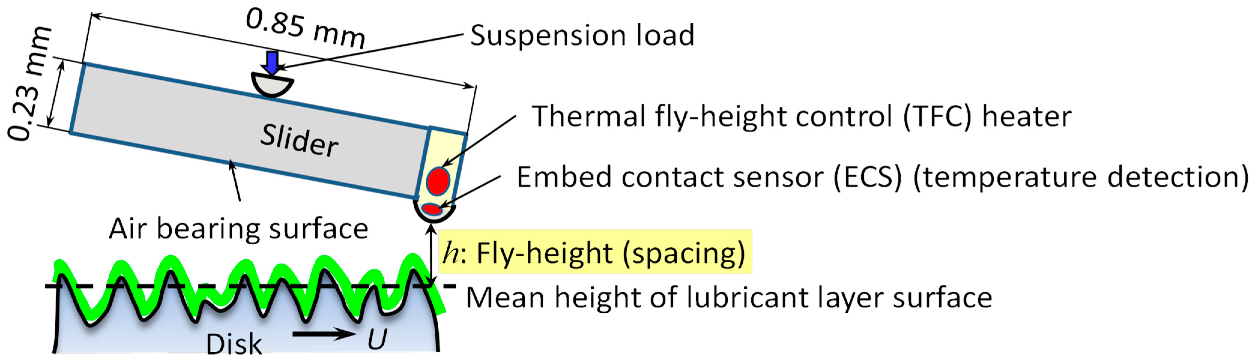
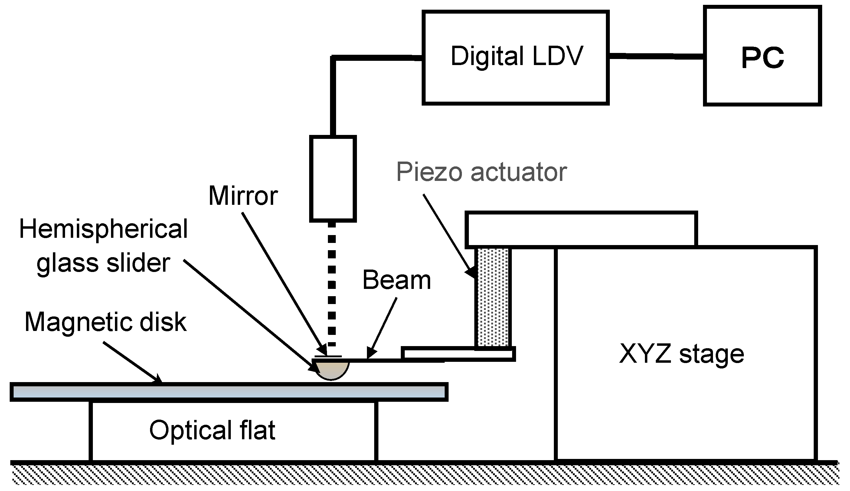
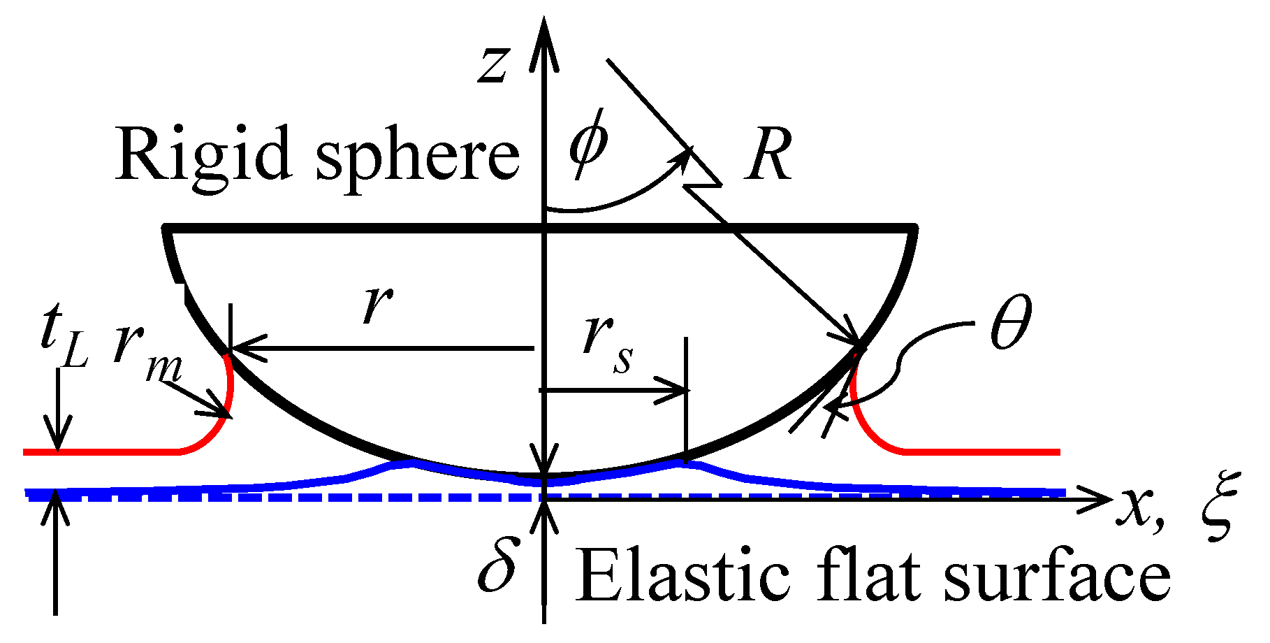
Table 1.
Surface roughness of magnetic disk tested (Citation from table 1 in [47]).
Table 1.
Surface roughness of magnetic disk tested (Citation from table 1 in [47]).
| Ra [nm] | Rq [nm] | Rp [nm] | Asperity RMS Height [nm] | Asperity Mean Height [nm] | Asperity Density [μm−2] |
|---|---|---|---|---|---|
| 0.52 | 0.67 | 5.6 | 0.309 | 0.524 | 31.28 |
Table 2.
Radius and surface roughness of hemispherical glass slider (scan area = 1.0 μm × 1.0 μm) (Citation from table 1 in [47]).
Table 2.
Radius and surface roughness of hemispherical glass slider (scan area = 1.0 μm × 1.0 μm) (Citation from table 1 in [47]).
| Radius [mm] | Ra [nm] | Rq [nm] | Rp [nm] | Asperity RMS Height [nm] | Asperity Mean Height [nm] | Asperity Density [μm−2] | Asperity Radius [μm] | |
|---|---|---|---|---|---|---|---|---|
| R1 slider | 1.00 | 1.71 | 2.13 | 5.80 | 0.962 | 3.48 | 56 | 0.66 |
| R2 slider | 2.00 | 0.34 | 0.33 | 1.62 | 0.151 | 0.56 | 179 | 1.36 |
Table 3.
Total and mobile lubricant thicknesses (Lubricant AM3001) (Citation from table 1 in [47]).
Table 3.
Total and mobile lubricant thicknesses (Lubricant AM3001) (Citation from table 1 in [47]).
| Target Lubricant Thickness | Without UV [nm] | With UV [nm] | ||||||
|---|---|---|---|---|---|---|---|---|
| Total Lube Thickness | σ | Mobile Lube Thickness | σ | Total Lube Thickness | σ | Mobile Lube Thickness | σ | |
| 1.0 nm | 1.20 | 0.02 | 0.69 | 0.02 | 1.08 | 0.04 | 0.43 | 0.01 |
| 2.0 nm | 2.19 | 0.02 | 1.48 | 0.02 | 2.18 | 0.02 | 0.98 | 0.04 |
| 3.0 nm | 3.07 | 0.05 | 2.42 | 0.02 | 3.24 | 0.07 | 1.65 | 0.04 |
Disclaimer/Publisher’s Note: The statements, opinions and data contained in all publications are solely those of the individual author(s) and contributor(s) and not of MDPI and/or the editor(s). MDPI and/or the editor(s) disclaim responsibility for any injury to people or property resulting from any ideas, methods, instructions or products referred to in the content. |
© 2024 by the author. Licensee MDPI, Basel, Switzerland. This article is an open access article distributed under the terms and conditions of the Creative Commons Attribution (CC BY) license (https://creativecommons.org/licenses/by/4.0/).
Share and Cite
MDPI and ACS Style
Ono, K. Physics of the Sub-Monolayer Lubricant in the Head-Disk Interface. Lubricants 2024, 12, 117. https://doi.org/10.3390/lubricants12040117
AMA Style
Ono K. Physics of the Sub-Monolayer Lubricant in the Head-Disk Interface. Lubricants. 2024; 12(4):117. https://doi.org/10.3390/lubricants12040117
Chicago/Turabian StyleOno, Kyosuke. 2024. "Physics of the Sub-Monolayer Lubricant in the Head-Disk Interface" Lubricants 12, no. 4: 117. https://doi.org/10.3390/lubricants12040117
Note that from the first issue of 2016, this journal uses article numbers instead of page numbers. See further details here.