Optimal Design of Boundary Angle for Gas Foil Thrust Bearing Thermal Performance
by
 ,
,
Bin Hu
1,2 ,
,
Anping Hou
1,2,*,
Rui Deng
1,
Xiaodong Yang
1,2,
Zhiyong Wu
3,
Qifeng Ni
4 and
Zhong Li
2 1
School of Energy and Power Engineering, Beihang University, Beijing 100191, China
2
Zhengzhou Aerotropolis Institute of Articial Intelligence, Zhengzhou 451162, China
3
The Key Laboratory of Solar Thermal Energy and Photovoltaic System, IEE-CAS, Beijing 100190, China
4
Ningbo Hudu Energy Technology Co., Ltd., Ningbo 315000, China
*
Author to whom correspondence should be addressed.
Lubricants 2024, 12(5), 143; https://doi.org/10.3390/lubricants12050143
Submission received: 10 March 2024
/
Revised: 13 April 2024
/
Accepted: 23 April 2024
/
Published: 24 April 2024
Abstract
:As the energy density and efficiency requirements of air compressors continue to increase, gas foil thrust bearings face a high risk of thermal failure due to their elevated speed and limited cooling space. This paper proposes a novel structure for gas foil thrust bearings with enhanced thermal characteristics. A thermo-elastic–hydrodynamic model is developed using a thermal-fluid–solid interaction approach to investigate aerodynamic and thermal performance. The load capacity and thermal characteristics of nine different boundary angles are analyzed. The model is validated, and the actual characteristics of gas foil bearings with various boundary angles are examined using a test rig. The results indicate that, compared to conventional gas foil thrust bearings with a boundary angle of 0°, the new structure with a boundary angle ranging from −10° to −5° not only maintains the load carrying capacity but also improves thermal characteristics. Furthermore, this improvement becomes more pronounced with higher rotational speeds. Therefore, the proposed optimization is advantageous in reducing the risk of thermal failure.
1. Introduction
With the global push towards carbon neutrality, the energy industry is demonstrating a trend towards decarbonization [1]. The Proton Exchange Membrane Fuel Cell (PEMFC) emerges as a competitive clean energy source with high efficiency, energy density, and zero emissions, garnering widespread attention and interest. The air compressor, responsible for pressurizing and transporting oxygen into the reactor, stands as one of the core components of PEMFC. Being an auxiliary equipment primarily consuming energy, it demands high efficiency. Additionally, to prevent contamination of the reactor catalyst due to lubricating oil, oil-free lubrication is imperative for the air compressor [2]. A gas foil bearing (GFB), characterized by oil-free operation and boasting high speed, efficiency, and long service life [3], aligns perfectly with the requirements of the air compressor, making it a prevalent choice in PEMFC air compressors [4,5,6]. However, with the continual increase in power density and rotational speed of the air compressor, coupled with the diminishing cooling space for the gas foil thrust bearing (GFTB), the susceptibility to thermal failure escalates. Hence, there is significant merit in developing GFTBs endowed with efficient heat dissipation characteristics.
GFBs are typically classified into gas foil journal bearings (GFJBs) and GFTBs, which handle radial and thrust loads, respectively. In the realm of GFB-rotor systems, the stability of the rotor system is primarily influenced by the GFJB, while the GFTB has a lesser impact on rotor stability but shares fundamental physics with the GFJB [7]. Consequently, GFTBs have not garnered significant attention from researchers in past decades, resulting in relatively scarce studies in this area. Initially, efforts were concentrated on enhancing the load capacity of GFTBs. Heshmat et al. [8] integrated a two-dimensional (2D) compressible Reynolds equation and a foil deformation equation to explore the load capacity of GFTBs. They simplified the foil structure to a linear elastic support structure with uniform stiffness distribution. Subsequent research by the same authors [9] delved into the impact of circumferential distribution of wave foil stiffness on thrust bearing capacity, revealing that higher stiffness at the fixed end led to increased bearing capacity. Iordanoff [10] introduced a foil structure model where stiffness linearly increased from the free end to the fixed end, considering stiffness variations between individual bumps due to Coulomb friction and constraints. Park et al. [11] utilized the finite element method to analyze foil structure deformation, accounting for bump interactions to enhance load capacity predictions. Lee et al. [12] experimentally examined the relationship between thrust force and foil deformation in a stationary state, determining foil structure stiffness characteristics through fitting methods. They modified the Reynolds equation to include rarefied gas slip flow. San Andrés et al. [13] employed a 2D flat shell for finite element analysis of top foil sagging, simplifying bump foils as distributed springs in each bump. Lehn et al. [14] utilized the Reissner–Mindlin type shell to model top and bump foils, investigating Coulomb friction effects, constraints, bump interactions, and top foil sagging comprehensively to enhance load capacity predictions. Xu et al. [15] considered the 2D frictional contact between foil structures based on Lehn et al.’s [14] model due to the curved shape of bump foils. Notably, none of the studies mentioned above addressed the impact of temperature on GFTB performance.
However, thermal failure is a critical issue that impacts the performance of gas foil thrust bearings (GFTBs) at high rotational speeds. Bruckner [16] conducted a study to analyze temperature variations during operation by coupling the 2D energy equation with the joint 2D Reynolds equation and foil deformation equation to investigate the load capacity and thermal characteristics of GFTBs. Building upon this work, Bruckner et al. [17] incorporated the Knudsen number effect into the Reynolds equation to enhance the accuracy of temperature distribution predictions. Lee et al. [18] explored the thermal characteristics of the bearings using 3D energy equations, treating each bump as a lumped thermal resistance. Their findings highlighted that thermal expansion of the thrust disk and thrust plate was the primary contributor to thermal failure in the bearings. To simplify the solution process for the Reynolds and energy equations, Mahner et al. [19] compared the results from five simplified methods, determining that the averaging method was well-suited for GFTBs due to the small temperature gradient in the air film thickness direction. In a study by Lehn et al. [20], the energy equation was solved considering viscosity and density variations with temperature, with each bump simplified as two thermal resistances of the haft bump arc. The research reaffirmed that high speeds and temperatures could result in thermal deformation of the thrust disk, a key factor in thermal failure. Kumar et al. [21] introduced first-order slip to modify the Reynolds equation, incorporating temperature-dependent viscosity and density in the energy equation to predict the aerodynamic and thermal performance of GFTBs. Their results indicated that neglecting first-order slip led to increased load capacity and reduced temperature in the predictions. However, the aforementioned studies employed the 2D Reynolds equation to model gas film flow and utilized equivalent thermal resistance to simplify the foil structure, potentially impacting the accuracy of bearing performance predictions.
Recently, Qin et al. [22] employed a three-dimensional (3D) thermal-fluid–solid interaction (TFSI) approach with high solution accuracy to predict the performance of GFTBs. This approach involved investigating air flow by solving the Navier–Stokes equation for the lubricating air film, and addressing structural and energy equations to analyze foil deformation and heat transfer, respectively. However, due to the disparity in time scales between equilibrating the temperature field and achieving convergence in fluid–solid coupling calculations, the authors opted for a weak coupling between the heat transfer and fluid solvers. In a study by Liu et al. [23], a more precise two-way TFSI approach was utilized to examine the impact of ambient pressure and rotational speed on the aerodynamic and thermal performance of GFTBs. Similarly, Gao et al. [24] applied the same approach to investigate the influence of top-foil wedge shape on the aerodynamic and thermal performance. Their findings indicated that employing the optimized top-foil wedge shape can significantly reduce the maximum temperature, but have little effect on the average temperature. Furthermore, Xiong et al. [25] developed a thermos-elastic-hydrodynamic (THED) model to explore the thermal failure mechanism of bearings and the effect of forced cooling air on the thermal characteristics of GFTBs. The results demonstrated that forced cooling air could effectively mitigate the risk of thermal failure. However, as the cooling space within GFTBs diminishes, the flow of forced cooling air decreases, rendering GFTBs more vulnerable to thermal failure at high speeds.
To further mitigate the risk of thermal failure, this paper introduces a novel structure for GFTBs with efficient heat dissipation properties. The study employs a TFSI approach to construct a detailed 3D thermo-elastohydrodynamic (TEHD) model of the GFTB, considering the actual deformations of the comprehensive foil structure and temperature distributions. The impact of boundary angles on the aerodynamic and thermal performance is investigated. To validate the numerical findings, various boundary angles are compared against experimental data obtained from a test rig. A detailed analysis of how the boundary angles affect load capacity and thermal characteristics is provided. Moreover, the enhanced thermal characteristics of the novel GFTBs are expected to drive advancements in the high-power-density rotating machinery industry.
2. Numerical Method
2.1. Description of the Novel GFTB
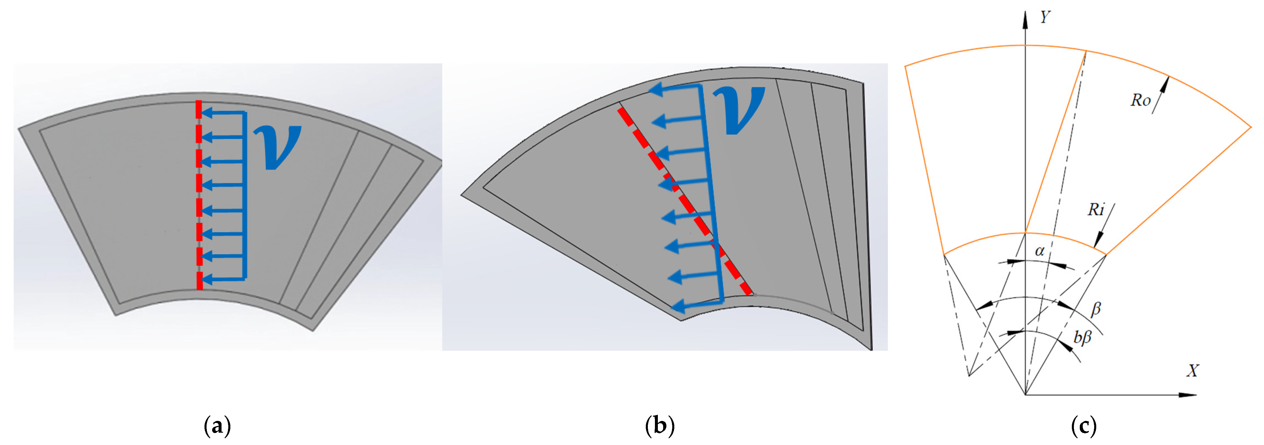
The novel GFTB with six pads, as depicted in Figure 1, consists of a top foil, a bump foil divided into three independent strips of equal width, and a spacer. The convergence area formed by the top foil and thrust disk establishes a high-pressure lubricating gas film, generating the thrust force. The top foil is segmented into the ramp area and the flat area based on their distinct functions, delineated by a boundary line marked with a red dashed line in both Figure 1 and Figure 2. Traditionally, the 2D compressible Reynolds equation of the gas film is solved in a cylindrical coordinate system for GFTBs. In this setup, the boundary line typically passes through the circle’s center, and the linear velocity of the thrust disk is perpendicular to the boundary line, as illustrated in Figure 2a. When the boundary angle deviates from 0°, altering the orientation of the linear thrust velocity with respect to the boundary line, adjustments in the gas film’s pressure distribution can be made to reduce heating duration in the high-pressure gas film region. This enhancement effectively improves the thermal characteristics of the novel GFTB, as depicted in Figure 2b. For increased load capacity, it is common practice to secure the bump foil at the trailing edge [15,26] and adopt an optimal ramp extent ratio of 0.5 [10,27].
In order to examine the influence of the boundary angle on GFTB performance, GFTBs with nine distinct boundary angles, featuring identical ramp extent ratios and ramp heights, are designed (refer to Figure 3). The boundary angles are spaced at intervals of 5°, labeled as bearings from −20° to +20°. All nine bearings share identical foil structure parameters, as outlined in Table 1 and visually represented in Figure 4.
2.2. Computational Domains and Governing Equations
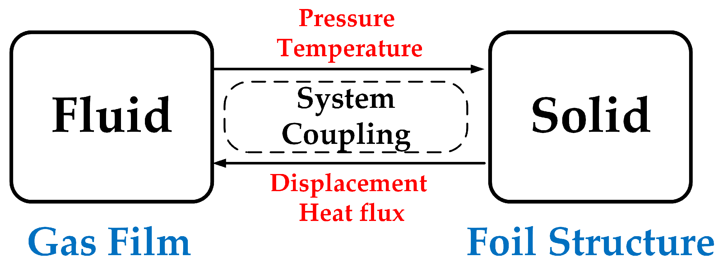
Based on the TFSI approach, the computational flow for the GFTBs is depicted in Figure 5. Initially, the fluid domain of the gas film undergoes solution by the Computational Fluid Dynamics (CFD) solver, wherein the pressure and temperature of the gas film at the fluid–solid interface are computed. Subsequently, these parameters on the fluid–solid interface are established as boundary conditions for the solid domain. The Finite Element Method (FEM) is then employed to solve the solid domain representing the foil structure, yielding displacement and heat flux data at the fluid–solid interface. Following this, the fluid domain is re-solved with the parameters from the fluid–solid interface serving as boundary conditions. Ultimately, through iterative solution cycles between the fluid and solid domains, the load capacity and thermal characteristics of the GFTBs can be determined.
The governing equations for all computational domains are presented below. The continuity equation in the fluid domain is expressed as:
where is the density of the gas, is the time, and is the velocity vector.
The momentum equation in the fluid domain is expressed as:
where , , and are the pressure, stress tensor, and external force, respectively.
The energy equation in the fluid domain is expressed as:
where is the specific heat capacity of the gas at constant pressure, is the absolute temperature, is the heat conduction flux of the gas, and is the total heat source.
And the energy equation in the solid domain is expressed as:
where is the specific heat capacity of the foil structure at constant pressure and is the heat conduction flux of the foil structure.
In this study, numerical simulations of the fluid domain are performed using the CFX commercial software in ANSYS. The SST k-ω turbulent model is selected for optimal accuracy [28]. The momentum and pressure terms employ the high-resolution discrete scheme, while the turbulence terms utilize the first-order discrete scheme. Additionally, the discrete time terms are addressed using the second-order explicit integration scheme. The semi-implicit solution of the pressure coupling equations (SIMPLE algorithm) is iteratively applied to solve the fluid domain, yielding distributions of pressure and temperature. In the solid domain, the mechanical commercial software in ANSYS is employed to analyze the transient thermoelastic dynamics of the foil structure. The thermal–structure element is utilized, and the governing equations are solved through the Newmark-β time integral method. Due to the inherent mismatch in mesh nodes between the fluid and solid domains at the fluid–solid interface, the workbench commercial software in ANSYS is utilized for parameter interpolation. This process facilitates the transfer of parameters between the fluid and solid domains, ensuring accurate representation and communication between the two computational domains.
2.3. Boundary Condition
For the TFSI calculation, the boundary conditions for the GFTBs are illustrated in Figure 6. Within the fluid domain, the end faces of the GFTB pad are assigned periodic boundary conditions. The inner and outer diameters of the bearing are set as opening boundaries with mass and momentum terms enrolled, while the ambient temperature and pressure are maintained at 25 °C and 1 atm, respectively. The surface of the thrust disk is designated as a moving no-slip wall, rotating counterclockwise. The top foil surface is specified as a stationary no-slip wall, serving as the fluid–solid interface. Given the thrust disk speed ranging from 10 krpm to 30 krpm, the thermal boundary condition for the thrust disk is modeled as forced convective heat transfer. Utilizing the forced heat transfer model calculation method [25,29], the convective heat transfer coefficient for the thrust disk at 30 krpm is determined to be 100 .
In the solid domain, the end faces of the GFTB pad are also subjected to periodic boundary conditions. The back plate and spacer are treated as fixed rigid bodies, while the fixed edges of the foil structure are set as fixed boundary conditions. Friction contact boundary conditions are applied at the contact surfaces between the foil structure and the back plate, employing 2D contact units with 174 contacting and 170 target units. The augmented Lagrange method is employed to calculate the contact state and friction, with a lower normal stiffness coefficient to expedite convergence. The friction coefficient between the foil structure and the back plate is set at 0.1 based on prior research [30,31]. The upper surface of the top foil is designated as the fluid–solid interface, while the remaining free zones of the foil structure and back plate are subjected to natural convection heat transfer conditions. The convective heat transfer coefficient is set at 12 using the natural convection heat transfer model calculation method [25], with the ambient temperature maintained at 25 °C.
2.4. Mesh
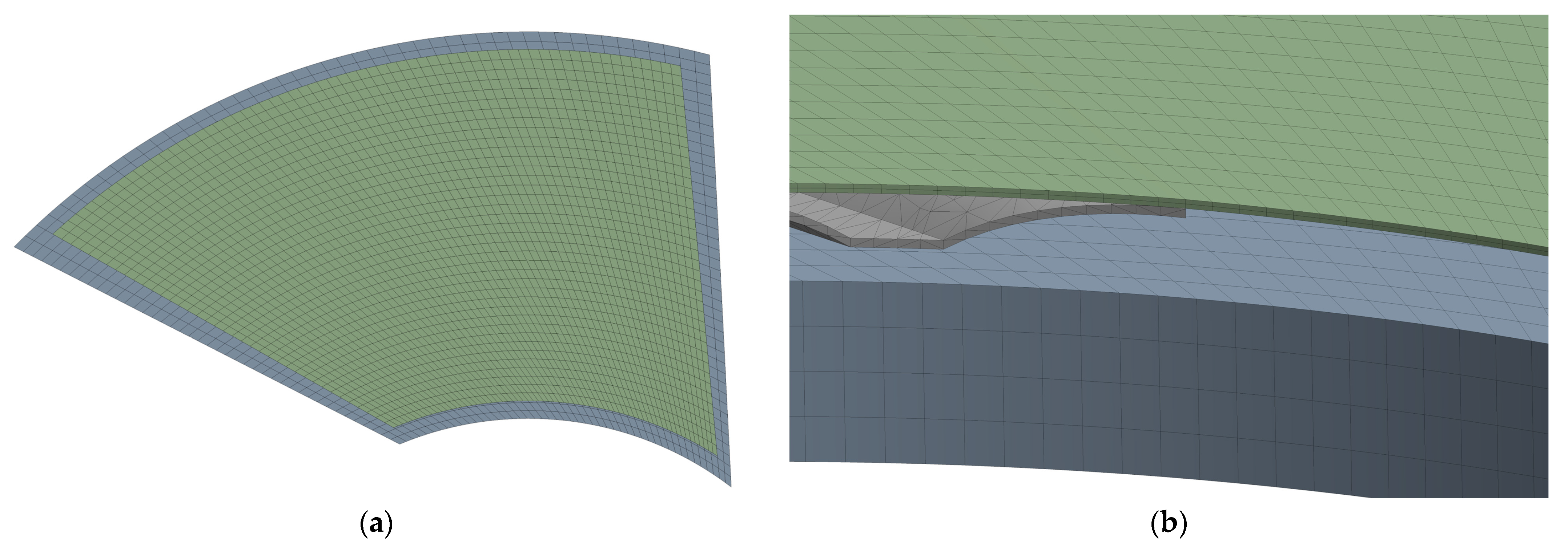
The mesh is generally divided into structured and unstructured types, with structured mesh offering higher calculation accuracy. Given the simplicity of the fluid domain in the GFTB, a structured mesh is employed, as depicted in Figure 7 for the fluid domain and Figure 8 for the solid domain. Structured hexahedral meshing is utilized for the top foil, spacer, and back plate, while the more complex geometric structure of the bump foil necessitates an unstructured tetrahedral mesh.
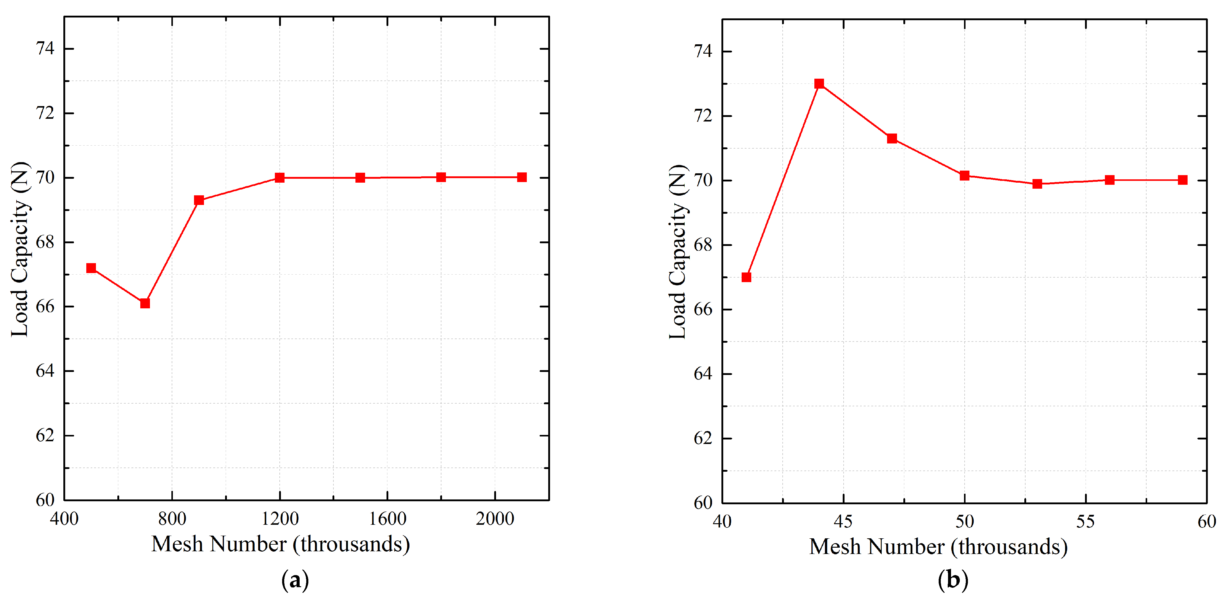
The mesh density significantly impacts numerical results. To prevent calculation errors due to insufficient mesh density or excessive resource consumption from overly dense meshes, it is crucial to assess mesh independence in both the fluid and solid domains to determine the optimal mesh density. Mesh refinement involves uniform refinement along the bearing circumference, radial direction, and gas film thickness direction to maintain mesh aspect ratio stability. Given the emphasis on load capacity in this study, load capacity serves as the metric for evaluating mesh independence. The variation in load capacity with mesh density is illustrated in Figure 9. As the mesh density in both the fluid and solid domains exceeds a certain threshold, the load capacity stabilizes. Consequently, for a balance between calculation accuracy and computational efficiency, mesh densities of 1.2 million and 53,000 are selected for the fluid and solid domains, respectively.
3. Experimental Methodology
To validate the effectiveness of the numerical method based on the TFSI approach and to comprehensively study the actual characteristics of GFTBs with varying boundary angles, an experimental rig for testing load capacity and thermal characteristics is established. The GTFB test rig, depicted in Figure 10, primarily comprises four components: the drive section responsible for rotating the thrust disk at high speed, the load section for applying thrust load, the data acquisition system for gathering friction torque, thrust load, and temperature data, and the test GFTBs.
3.1. Test Rig
Since the aim of this study is to investigate the load capacity and thermal characteristics of the GFTBs, the experimental setup requires stable operation at a fixed speed over a duration to measure thrust load, friction force, and temperature accurately. Therefore, the test rig must precisely control the speed without fluctuations, while the drive section should achieve the highest possible maximum speed. As per design specifications, the drive section’s structure is illustrated in Figure 11a. Three precision ceramic angular contact bearings are utilized, positioned at both ends of the shaft. Since the shaft experiences a unidirectional horizontal thrust force throughout the test, the front support incorporates two large-sized precision ceramic angular contact bearings arranged in series to balance their contact angle lines and evenly distribute the thrust load. The rear support features a small-sized precision ceramic angular contact bearing pre-loaded by a spring to enhance shaft stability at high speeds. Given the high-speed requirements of the drive section, a gas–liquid two-phase fluid cooling lubrication technology is employed for the bearings. High-pressure mixed oil-gas generated by the lubrication device is sprayed into the bearing at a specific angle through oil-gas nozzles. This method not only lubricates the bearing effectively but also dissipates heat and cools the bearing efficiently. The lubricated and cooled high-pressure mixture is circulated from the drive section’s base through three vacuum generators to prevent bearing overheating due to excess lubricating oil. Additionally, oil-gas sealing slots are placed at both ends of the drive section to prevent oil discharge and environmental pollution. Given the high-speed operation of the motor, characterized by a high energy density and a limited heat dissipation area, a liquid cooling scheme is exclusively employed to meet cooling requirements. Cooling water from the chiller flows through a spiral cooling channel to dissipate surrounding heat effectively, ensuring efficient cooling of the high-speed motor. To validate the drive section’s design, finite element analysis software SAMCEF is used to analyze the modal dynamics of the rotating shaft. Finite element modeling and modal analysis reveal that the critical speed of the first-order bending mode of the drive section’s shaft is 73.84 krpm, meeting the high-speed operation requirements of the thrust plate on the test bench.
And the structure of the load part is depicted in Figure 11b. The test GFTB is secured on the bearing housing using flat round head hexagon screws. A through hole is machined in the center of the bearing housing and the loading shaft, serving as an air exchange channel to maintain the inner diameter of the test GFTB at external atmospheric pressure. The loading shaft is supported by two hydrostatic gas bearings of varying sizes. These bearings achieve suspension by utilizing external high-pressure air supply, ensuring high rotation accuracy and minimal friction moment. This setup significantly enhances friction measurement accuracy. The thrust load in the loading section is generated by these two hydrostatic gas bearings of different sizes. Upon entry of high-pressure air into the hydrostatic gas bearing, it is expelled through the pneumatic nozzle. The high-pressure air flows through the air gap between the loading shaft and the hydrostatic gas bearing. A portion of the air is released into the external atmosphere, while the remainder enters the pressure chamber within the middle of the loading section. Due to the size disparity between the two hydrostatic gas bearings, a step surface is formed on the loading shaft, resembling a piston structure. This configuration results in the generation of unidirectional thrust load under the influence of high-pressure air in the pressure chamber. The formula for calculating the thrust load is as follows:
where represents the pressure in the high-pressure air chamber, is the diameter of the front hydrostatic gas bearing, and is the diameter of the rear hydrostatic gas bearing.
Since the pressure in the pressure chamber can be smoothly adjusted by a precision pressure regulator, the thrust load can also be adjusted incrementally. During testing, the maximum pressure in the high-pressure air chamber can reach 160 kPa. According to the calculation from Equation (5), the maximum thrust loading is 80 N. Since the thrust load is always perpendicular to the step surface, and the step surface is perpendicular to the axis of the loading shaft, the magnitude of the thrust load changes while its direction remains collinear with the axis of the loading shaft.
3.2. Test Measurement System
The test system of the test rig is utilized for measuring friction torque, thrust load, and temperature. The friction torque and thrust load play a crucial role in characterizing the operational state of the lubricating gas film. The friction force is gauged using an S-type tension sensor, dynamic signal analysis system, and an industrial computer, while the thrust load is monitored with a digital pressure gauge. Temperature data is pivotal for assessing thermal behavior, and temperature readings are captured using K-type thermocouples and a temperature recorder.
To ensure the feasibility of securing the K-type thermocouples, temperature readings are taken from the backside of the back plate and the top foil. The temperature measurement locations on the back plate are illustrated in Figure 12. Initially, four evenly spaced K-thermocouple mounting slots are created on the bearing housing using precision wire cutting equipment. Subsequently, the K-type thermocouples are affixed in these slots at radii of 22 mm and 38 mm using high thermal conductivity curable silica gel. In total, eight K-type thermocouples are strategically positioned on the bearing housing.
The temperature measuring points on the top foils are depicted in Figure 13. Due to the limited space resulting from the small bump foil height and pitch, the K-type thermocouples can only be placed in the ramp area. To ensure accurate temperature readings on the backside of the top foil, a 0.05 mm thick copper foil tape with high thermal conductivity is used to secure the K-type thermocouples.
3.3. Test GFTBs
Both the top foil and bump foil are made of 3J1 high-elastic alloy and the top foil surface is coated with Teflon for enhanced performance. To experimentally investigate the impact of boundary angles on bearing performance, five types of GFTBs with boundary angles of −20°/−10°/0°/+10°/+20° are manufactured. Figure 14 illustrates the top and bump foils of these bearings. To minimize potential errors introduced by the surface coating quality of the top foil, a preliminary series of 100 start–stop runs under a thrust load of 20 N is conducted before the formal testing of the GFTBs.
4. Results and Discussion
4.1. Load Capacity
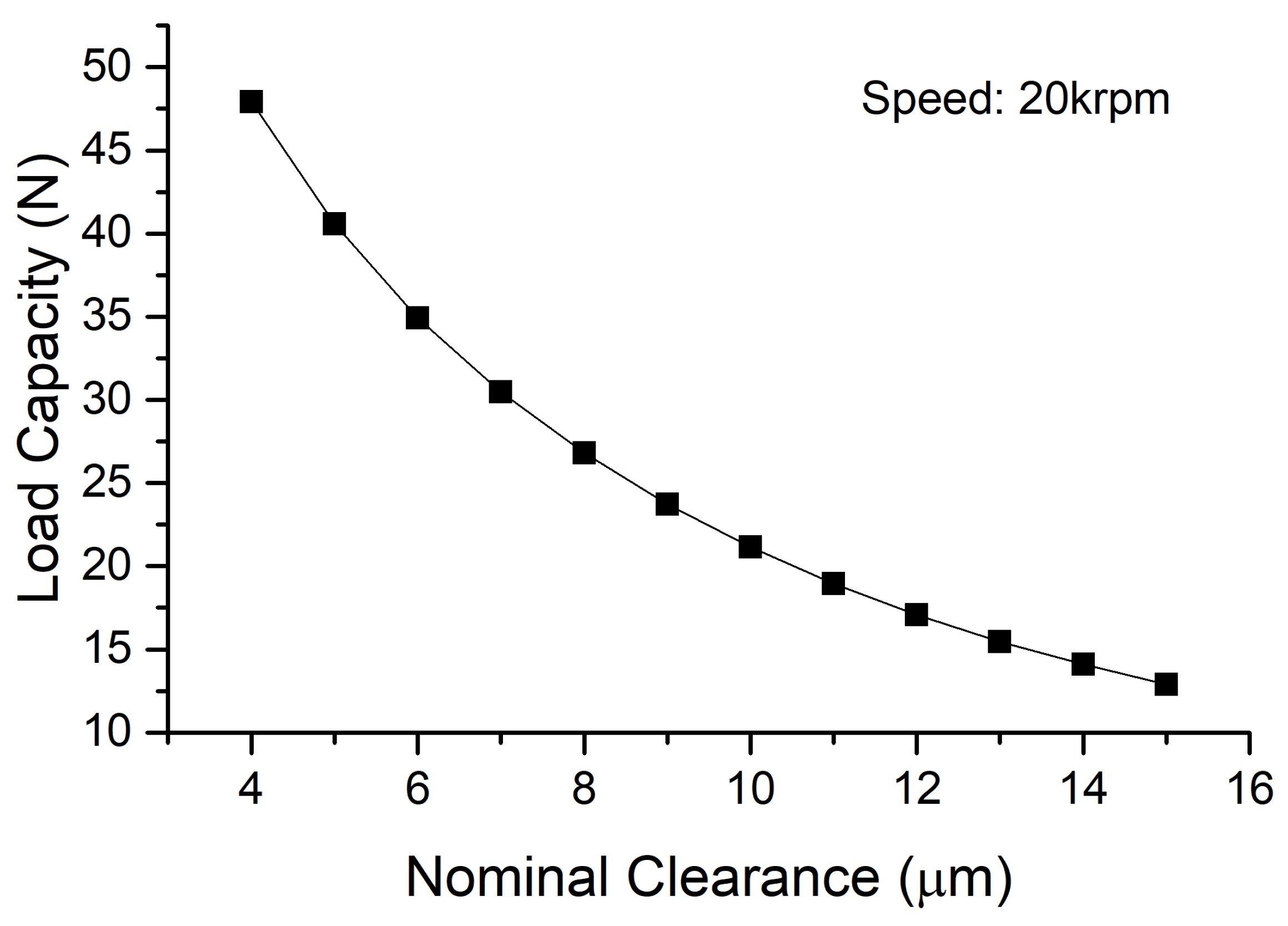
The comparison between the numerical results and the experimental results of the load capacity is illustrated in Figure 15. The boundary angle of the test GFTB is −10°, and the operating speed of the thrust disk remains stable at 20 krpm. As depicted in Figure 15, the friction torque increases gradually with the rise in thrust load. Under the same thrust load, the numerical results of the friction torque align closely with the experimental findings. However, when the thrust exceeds 50.9 N, there is a sudden surge in the experimental friction torque results. This abrupt increase is attributed to the disruption of the gas film and the resulting contact friction between the thrust disk and the top foil. Typically, the point at which this occurs is defined as the ultimate load capacity of GFTBs [10,13]. Analyzing the relationship between load capacity and nominal clearance, as shown in Figure 16, reveals that load capacity rises as nominal clearance decreases. The smaller the nominal clearance value, the greater the increase in load capacity. Considering the nominal clearance value indicated in Figure 15, the test GFTB with a boundary angle of −10° exhibits an ultimate load capacity at 20 krpm that closely matches the numerical results for a bearing with a nominal clearance of 4 μm. Generally, nominal clearances ranging from 3 μm to 5 μm are selected as the minimum values for numerical calculations to predict the ultimate load capacity of GFBs [32,33,34,35,36]. Hence, the minimum nominal clearance for the test GFTB in this study is set at 4 μm.
To investigate the impact of the boundary angle on the ultimate load capacity and validate the accuracy of predicting load capacity using the minimum nominal clearance of 4 μm, both experimental and numerical results of the ultimate load capacity with various boundary angles at three rotational speeds are presented in Figure 17. It is evident from the figure that, at identical rotational speeds, the ultimate load capacities of GFTBs with different boundary angles are relatively consistent, indicating that the boundary angle has minimal effect on load capacity when the holding ramp area ratio remains constant. Furthermore, the experimental and numerical results of the ultimate load capacity at each rotational speed and boundary angle exhibit a high degree of agreement, affirming the validity of setting the minimum nominal clearance at 4 μm for predicting GFTBs’ ultimate load capacity and confirming the accuracy of the numerical method based on the TFSI approach for load capacity prediction.
4.2. Thermal Characteristics
While the boundary angle has minimal effect on the load capacity, it significantly impacts the thermal characteristics of the GFTBs. The correlation between the numerical thermal characteristics and the boundary angle is depicted in Figure 18. Operating at a speed of 20 krpm, the thrust disk’s minimum nominal clearance is utilized for numerical calculations. In Figure 18a, it is evident that Bearing −10° exhibits the lowest average temperature on the top foil at 57.4 °C, whereas Bearing +5° displays a notably higher average temperature of 65.8 °C. The relationship between the total heat generation power and the boundary angles, as illustrated in Figure 18b, indicates a close similarity between the total heat generation power of Bearing −10° and Bearing +5°. The substantial disparity in the average temperatures of their top foils can be attributed to the significant difference in their heat dissipation power. The heat dissipation within the gas film primarily occurs through three mechanisms. Firstly, forced convection heat transfer on the thrust disk’s surface is a key method of heat dissipation. The convection heat transfer coefficient remains constant when the rotational speed is steady. The heat dissipation power of the thrust disk is directly proportional to the temperature differential between the thrust disk and the ambient air, as evident in the comparison between Figure 18a,c. Secondly, heat dissipation occurs through heat conduction and natural convection from the top foil to the foil structure and ambient air. Figure 18d illustrates the relationship between the heat dissipation power of the top foil and the boundary angle. Bearing −10° exhibits the highest heat dissipation power, significantly surpassing that of Bearing +5°. The final heat dissipation pathway involves air flowing through the inner and outer diameter regions of the GFTB, transferring heat from the gas film to the ambient air. However, due to the minimal air exchange within the gas film, the heat dissipation power through this pathway is negligible and is therefore disregarded in this analysis. Consequently, adhering to the principle of energy conservation, the heat balance of the foil thrust bearing can be expressed as:
where represents the total power of heat generation, is the heat dissipation power of top foil, and is the heat dissipation power of thrust disk.
The heat dissipation power of the thrust disk is expressed as:
where is the forced thermal convection coefficient, is the average temperature of the thrust disk, and is the temperature of the ambient air.
Substituting Equation (7) into Equation (6), the formula for the average temperature of the thrust disk is obtained:
As indicated in Equation (8), assuming a constant total heat generation power , the forced convection heat transfer coefficient of the thrust disk remains constant due to the steady speed of the thrust disk. When the heat dissipation power of the top foil is higher, less heat is transferred through the thrust disk, resulting in a lower average temperature for the thrust disk after the top foil has transferred more heat. Consequently, the top foil exhibits a lower average temperature.
To further elucidate this phenomenon, Figure 19 illustrates the pressure distribution of four bearings with varying boundary angles. The numerical calculations are conducted with a thrust disk operating speed of 20 krpm and utilizing the minimum nominal clearance. A comparison between Figure 19b,d reveals that while the maximum pressure values of Bearing −10° and Bearing +5° are similar, Bearing −10° exhibits a larger high-pressure distribution area and the maximum pressure zone is located above the bump. The presence of a high-pressure gas film leads to increased deformation of the top foil, expanding the contact area between the top foil and the bump foil, consequently enhancing the heat dissipation power of the top foil. Conversely, the maximum pressure zone of Bearing +5° is between two bumps, resulting in a reduction in the contact area. Further comparison among Figure 19a–c demonstrates that although their high-pressure distribution areas are relatively similar, Bearing −10° boasts the highest maximum pressure value, followed by Bearing −5°, with Bearing −20° registering the lowest. As pressure increases, the deformation of the top foil intensifies, resulting in a larger contact area between the top foil and the bump foil. Consequently, Bearing −10° exhibits the highest heat dissipation power.
The relationship between the maximum temperature of the top foil and the boundary angles is depicted in Figure 20. Notably, the maximum temperature of the top foil for Bearing −5° is the lowest among all angles considered, showcasing a significant deviation from the temperatures observed for other angles. To delve into this phenomenon further, Figure 21 illustrates the temperature distribution of the top foil and temperature values along the streamlines across the four bearings with varying boundary angles. The end points of the streamlines are set at the outer diameter region of the flat area. For Bearing −5°, the maximum temperature point is situated in proximity to the boundary lines and the outer diameter of the bearing. In contrast, for Bearing −10°, the maximum temperature point is slightly distanced from the boundary line. The maximum temperature position for Bearing +5° aligns near the trailing edge, while for Bearing −20°, it is positioned close to the intersection of the trailing edge and the bearing’s outer diameter. By combining insights from Figure 19 and Figure 21, a compelling narrative emerges. When the GFTB is Bearing −5°, the high-pressure distribution area is adjacent to the boundary lines and the outer diameter of the bearing. As the heated air swiftly exits this region into the ambient air, the top foil experiences lower temperatures due to the brief exposure to the high-pressure gas film, which is depicted in Figure 21(c2). Conversely, for Bearing −20°, the high-pressure distribution area is concentrated near the trailing edge and the center diameter of the bearing. As shown in Figure 21(a2), this configuration leads to a longer duration of air heating in the flat area, resulting in elevated temperatures. Furthermore, in the case of Bearing −10° and Bearing +5°, the high-pressure distribution area is close to the boundary line but near the center diameter of the bearing. Figure 21(b2,d2) illustrate their temperature values along the streamlines; part of the air leaves the flat area after a short heating duration, causing their moderate temperatures. Consequently, the top foil of Bearing −5° exhibits the lowest maximum temperature among the bearings studied.
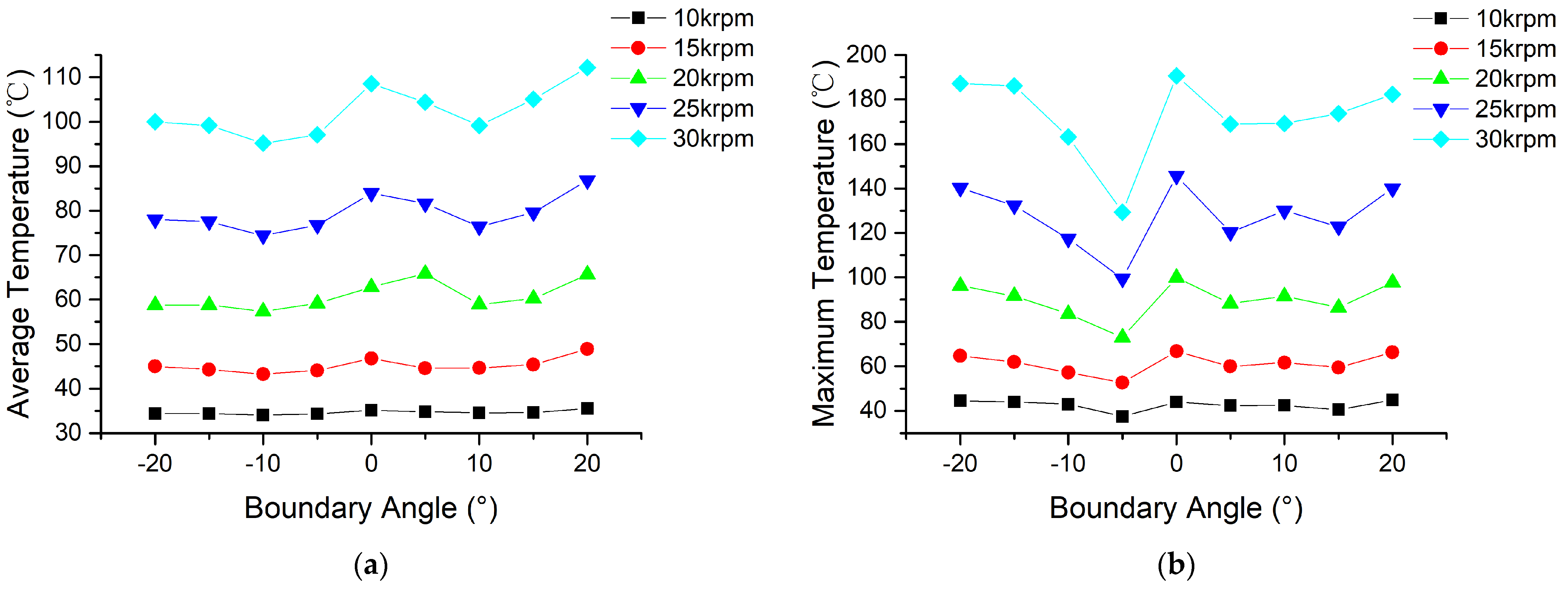
In order to delve deeper into the impact of boundary angles on thermal characteristics, an examination of how these angles influence the top foil temperature at varying rotational speeds was conducted. As depicted in Figure 22, both the average and maximum temperatures of the top foils exhibit an increase as the rotational speed escalates. Remarkably, Bearing −10° consistently displays the lowest average temperature, while Bearing −5° consistently records the lowest maximum temperature across all rotational speeds analyzed. These findings underscore the efficacy of boundary angles ranging from −10° to −5° in enhancing the thermal performance of GFTBs. Moreover, the magnitude of this enhancement becomes more pronounced with higher rotational speeds. In essence, the results advocate for the utilization of boundary angles within the −10° to −5° range as an effective strategy to bolster the thermal characteristics of GFTBs, with a notable amplification of this effect observed at elevated rotational speeds.
To validate the numerical findings regarding thermal characteristics, this study conducts measurements of the backside temperatures of both the top foil and the back plate. The temperature measurement points for the top foils encompass three points situated in the ramp area, while those for the back plate comprise four outer and four inner measuring points. Given the uniform distribution of temperature measurement points in the circumferential direction and the close proximity of temperatures at identical radial locations in the experiment, average temperature values are computed.
Due to the considerable time required to attain thermal equilibrium and challenges in maintaining a constant ambient temperature, the study opts to analyze temperature variation values, representing the temperature disparity between the measurement point temperature and the ambient temperature. Figure 23 illustrates the comparison of temperature variation across different boundary angles. Notably, in both numerical and experimental outcomes, Bearing −10° exhibits the least temperature rise at the top foil measurement point, as depicted in Figure 23a. Discrepancies between the temperature variation values in experimental and numerical results arise from the absence of the bump foil region in the fluid domain of the numerical simulations. The airflow within the bump foil region enhances the heat dissipation capability of the top foil, resulting in a reduced temperature rise at the thrust flat foil temperature measurement point in the experimental data compared to the numerical predictions. Regarding the temperature variation of the back plate illustrated in Figure 23b, the temperature variation values for both outer and inner measurement points remain consistent across varying boundary angles, aligning with the numerical results. However, the temperature variation values in the experimental data are lower than those in the numerical simulations, attributed to the continuous cooling airflow generated by the hydrostatic gas bearings within the bearing housing, as depicted in Figure 11b. In conclusion, the numerical approach based on the TFSI method proves effective in predicting thermal characteristics, despite discrepancies between experimental and numerical results stemming from factors such as the absence of the bump foil region in numerical simulations and the cooling airflow facilitated by the hydrostatic gas bearings.
5. Conclusions
In this study, we introduce a novel structure for GFTBs designed to enhance thermal characteristics. Employing the TFSI approach, we develop a detailed 3D TEHD model of the GFTB that considers the actual foil structure without significant simplifications. This model is utilized to analyze various boundary angles to understand temperature variation mechanisms and optimize angles for mitigating the risk of thermal failure in GFTBs. To validate the model and comprehensively explore the performance of GFTBs with different boundary angles, an experimental setup is established to test load capacity and thermal properties, with the model’s accuracy confirmed through experimental results. Key conclusions drawn from the study are as follows:
- The load capacity increases as the nominal clearance decreases, with a more substantial capacity boost observed at smaller nominal clearance values. For the GFTBs examined in this study with a minimum nominal clearance of 4 μm, boundary angles do not impact the ultimate load capacity at varying rotational speeds.
- Bearing −10° exhibits higher air film pressure and a larger high-pressure air film area, leading to increased top foil deformation and contact area between the top foil and bump foil. Consequently, it demonstrates superior heat dissipation capabilities, resulting in the lowest average temperature of its top foil.
- The high-pressure distribution area of Bearing −5° is situated near the boundary line and the bearing’s outer diameter region. As heated air from the high-pressure air film enters the top foil’s flat area, it flows from the bearing’s outer diameter to the ambient air after a brief heating period. This configuration contributes to the lowest maximum temperature of the top foil among the studied angles.
- Novel GFTBs with boundary angles ranging from −10° to −5°, as opposed to conventional GFTBs with a 0° boundary angle, not only maintain load capacity but also enhance thermal characteristics. This improvement is more pronounced at higher rotational speeds, highlighting the efficacy of the novel design.
Author Contributions
Conceptualization, B.H. and A.H.; methodology, B.H.; software, R.D.; validation, B.H. and X.Y.; formal analysis, B.H.; investigation, B.H.; data curation, B.H.; writing—original draft preparation, B.H.; writing—review and editing, B.H. and Z.W.; resources, Q.N. and Z.L.; visualization, B.H.; supervision, A.H.; funding acquisition, A.H. All authors have read and agreed to the published version of the manuscript.
Funding
This research was funded by the National Science and Technology Major Project of China, grant number J2019-V-0017-0112.
Data Availability Statement
The data presented in this study are available on reasonable request from the corresponding author.
Conflicts of Interest
Author Qifeng Ni was employed by the company Ningbo Hudu Energy Technology Co., Ltd. The remaining authors declare that the research was conducted in the absence of any commercial or financial relationships that could be construed as a potential conflict of interest.
References
- Lee, J.; Cho, H.; Kim, J. Techno-economic analysis of on-site blue hydrogen production based on vacuum pressure adsorption: Practical application to real-world hydrogen refueling stations. J. Environ. Chem. Eng. 2023, 11, 109549. [Google Scholar] [CrossRef]
- Chen, S.; Zuo, S.; Wu, Z. Aerodynamic Performance Modeling of the Centrifugal Compressor and Stability Analysis of the Compression System for Fuel Cell Vehicles. SAE Int. J. Adv. Curr. Pract. Mobil. 2021, 3, 2325–2336. [Google Scholar] [CrossRef]
- Zhang, G.; Huang, M.; Chen, G.; Li, J.; Liu, Y.; He, J.; Zheng, Y.; Tang, S.; Cui, H. Design and optimization of fluid lubricated bearings operated with extreme working performances—A comprehensive review. Int. J. Extrem. Manuf. 2024, 6, 022010. [Google Scholar] [CrossRef]
- Hou, Y.; Zhao, Q.; Guo, Y.; Ren, X.; Lai, T.; Chen, S. Application of Gas Foil Bearings in China. Appl. Sci. 2021, 11, 6210. [Google Scholar] [CrossRef]
- Ha, K.-K.; Lee, C.H.; Kim, C.M.; Kim, S.H.; Ahn, B.K. A Study on the Characteristics of an Oil-Free Centrifugal Compressor for Fuel Cell Vehicles. SAE Int. J. Alt. Power 2016, 5, 167–174. [Google Scholar] [CrossRef]
- Agrawal, G.L. Foil Air/Gas Bearing Technology—An Overview. In Proceedings of the ASME 1997 International Gas Turbine and Aeroengine Congress and Exhibition, Orlando, FL, USA, 2–5 June 1997. [Google Scholar]
- DellaCorte, C.; Bruckner, R.J. Remaining Technical Challenges and Future Plans for Oil-Free Turbomachinery. J. Eng. Gas Turbines Power 2011, 133, 042502. [Google Scholar] [CrossRef]
- Heshmat, H.; Walowit, J.A.; Pinkus, O. Analysis of Gas Lubricated Compliant Thrust Bearings. J. Lubr. Technol. 1983, 105, 638–646. [Google Scholar] [CrossRef]
- Heshmat, H. Analysis of compliant foil bearings with spatially variable stiffness. In Proceedings of the 27th Joint Propulsion Conference, Sacramento, CA, USA, 24–26 June 1991. [Google Scholar]
- Iordanoff, I. Analysis of an Aerodynamic Compliant Foil Thrust Bearing: Method for a Rapid Design. J. Tribol. 1999, 121, 816–822. [Google Scholar] [CrossRef]
- Park, D.-J.; Kim, C.-H.; Jang, G.-H.; Lee, Y.-B. Theoretical considerations of static and dynamic characteristics of air foil thrust bearing with tilt and slip flow. Tribol. Int. 2008, 41, 282–295. [Google Scholar] [CrossRef]
- Lee, Y.-B.; Kim, T.Y.; Kim, C.H.; Kim, T.H. Thrust Bump Air Foil Bearings with Variable Axial Load: Theoretical Predictions and Experiments. Tribol. Trans. 2011, 54, 902–910. [Google Scholar] [CrossRef]
- San Andrés, L.; Ryu, K.; Diemer, P. Prediction of Gas Thrust Foil Bearing Performance for Oil-Free Automotive Turbochargers. J. Eng. Gas Turbines Power 2015, 137, 032502. [Google Scholar] [CrossRef]
- Lehn, A.; Mahner, M.; Schweizer, B. Elasto-gasdynamic modeling of air foil thrust bearings with a two-dimensional shell model for top and bump foil. Tribol. Int. 2016, 100, 48–59. [Google Scholar] [CrossRef]
- Xu, Z.; Li, C.; Du, J.; Li, J.; Wang, Y. Load-carrying characteristics of bump-type gas foil thrust bearings. Int. J. Mech. Sci. 2023, 244, 108080. [Google Scholar] [CrossRef]
- Bruckner, R.J. Simulation and Modeling of the Hydrodynamic, Thermal, and Structural Behavior of Foil Thrust Bearings. Ph.D. Thesis, Case Western Reserve University, Cleveland, OH, USA, 2004. [Google Scholar]
- Bruckner, R.J.; Dellacorte, C.; Prahl, J.M. Analytic Modeling of the Hydrodynamic, Thermal, and Structural Behavior of Foil Thrust Bearings. In Proceedings of the 2005 Annual Meeting and Exhibition, 60th Society of Tribologists and Lubrication Engineers, Las Vegas, NV, USA, 15–19 May 2005. [Google Scholar]
- Lee, D.; Kim, D. Three-Dimensional Thermohydrodynamic Analyses of Rayleigh Step Air Foil Thrust Bearing with Radially Arranged Bump Foils. Tribol. Trans. 2011, 54, 432–448. [Google Scholar] [CrossRef]
- Mahner, M.; Lehn, A.; Schweizer, B. Thermogas- and thermohydrodynamic simulation of thrust and slider bearings: Convergence and efficiency of different reduction approaches. Tribol. Int. 2016, 93, 539–554. [Google Scholar] [CrossRef]
- Lehn, A.; Mahner, M.; Schweizer, B. A thermo-elasto-hydrodynamic model for air foil thrust bearings including self-induced convective cooling of the rotor disk and thermal runaway. Tribol. Int. 2018, 119, 281–298. [Google Scholar] [CrossRef]
- Kumar, J.; Khamari, D.S.; Behera, S.K.; Sahoo, R.K. Influence of slip-flow phenomenon on thermohydrodynamic behaviour of gas foil thrust bearings. Proc. Inst. Mech. Eng. Part J J. Eng. Tribol. 2022, 236, 15–30. [Google Scholar] [CrossRef]
- Qin, K.; Jacobs, P.A.; Keep, J.A.; Li, D.; Jahn, I.H. A fluid-structure-thermal model for bump-type foil thrust bearings. Tribol. Int. 2018, 121, 481–491. [Google Scholar] [CrossRef]
- Liu, X.; Li, C.; Du, J. The Fluid-Structure-Thermal Performance Analysis of Gas Foil Thrust Bearing by Using Computational Fluid Dynamics. Lubricants 2022, 10, 294. [Google Scholar] [CrossRef]
- Gao, Q.-h.; Sun, W.-j.; Zhang, J.-z. Optimal design of top-foil wedge shape for a specific multi-layer gas foil thrust bearing by considering aerodynamic and thermal performances. Therm. Sci. Eng. Prog. 2023, 44, 102060. [Google Scholar] [CrossRef]
- Xiong, C.; Xu, B.; Yu, H.; Huang, Z.; Chen, Z. A thermo-elastic-hydrodynamic model for air foil thrust bearings considering thermal seizure and failure analyses. Tribol. Int. 2023, 183, 108373. [Google Scholar] [CrossRef]
- Xiong, C.; Xu, B.; Yu, H.; Huang, Z.; Chen, Z. Static and dynamic characteristics of aerodynamic thrust bearings based on fluid-thermal-structural interaction approach. Therm. Sci. Eng. Prog. 2023, 42, 101901. [Google Scholar] [CrossRef]
- Kim, T.H.; Park, M.; Lee, T.W. Design Optimization of Gas Foil Thrust Bearings for Maximum Load Capacity1. J. Tribol. 2017, 139, 031705. [Google Scholar] [CrossRef]
- Qin, K.; Li, D.; Huang, C.; Luo, K. Comparative analysis of turbulence models for gas bearings flowfield simulations. Fluid Dyn. Res. 2019, 51, 045505. [Google Scholar] [CrossRef]
- Xiong, C.; Xu, B.; Yu, H.; Huang, Z.; Chen, Z. Thermal failure optimization of foil thrust bearings. Int. J. Mech. Sci. 2024, 267, 109026. [Google Scholar] [CrossRef]
- Hoffmann, R.; Liebich, R. Experimental and numerical analysis of the dynamic behaviour of a foil bearing structure affected by metal shims. Tribol. Int. 2017, 115, 378–388. [Google Scholar] [CrossRef]
- Zywica, G.; Baginski, P.; Bogulicz, M.; Martowicz, A.; Roemer, J.; Kantor, S. Numerical identification of the dynamic characteristics of a nonlinear foil bearing structure: Effect of the excitation force amplitude and the assembly preload. J. Sound Vib. 2022, 520, 116663. [Google Scholar] [CrossRef]
- Dykas, B. Factors Influencing the Performance of Foil Gas Thrust Bearings for Oil-Free Turbomachinery Applications. Ph.D. Thesis, Case Western Reserve University, Cleveland, OH, USA, 2006. [Google Scholar]
- Kim, T.H.; Lee, Y.-B.; Kim, T.Y.; Jeong, K.H. Rotordynamic Performance of an Oil-Free Turbo Blower Focusing on Load Capacity of Gas Foil Thrust Bearings. J. Eng. Gas Turbines Power 2011, 134, 022501. [Google Scholar] [CrossRef]
- Conboy, T.M. Real-Gas Effects in Foil Thrust Bearings Operating in the Turbulent Regime. J. Tribol. 2013, 135, 031703. [Google Scholar] [CrossRef]
- Gao, Q.; Sun, W.; Zhang, J. Thermo-elasto-hydrodynamic analysis of a specific multi-layer gas foil thrust bearing under thermal-fluid–solid coupling. Chin. J. Aeronaut. 2023, 36, 231–246. [Google Scholar] [CrossRef]
- Zhang, J.-Y.; Qiao, X.-Y.; Chen, W.-D.; Chen, B.-X.; Lyu, Y.-W.; Luo, X.-Y. Numerical investigation of Thermo-aerodynamic characteristics of gas foil thrust bearing. Therm. Sci. Eng. Prog. 2022, 31, 101296. [Google Scholar] [CrossRef]
Figure 1.
Schematic of the novel GFTB. (a) Photo; (b) 3D geometrical model.

Figure 2.
Schematic diagram of one GFTB pad. (a) Bearing 0°; (b) Bearing −20°; (c) variables description.
Figure 2.
Schematic diagram of one GFTB pad. (a) Bearing 0°; (b) Bearing −20°; (c) variables description.

Figure 3.
Nine different boundary angle of GFTBs.

Figure 4.
Variables description of GFTB; (a) gas film; (b) foil structure.

Figure 5.
Computational flow of TFSI.

Figure 6.
Computational domains. (a) Fluid domain; (b) structure domain.

Figure 7.
Fluid domain mesh. (a) Global; (b) local.

Figure 8.
Solid domain mesh. (a) Global; (b) local.

Figure 9.
Mesh independence test. (a) Fluid domain; (b) solid domain.

Figure 10.
Photo of test rig.

Figure 11.
Structure of test rig; (a) drive part; (b) load part.

Figure 12.
Temperature measurement points layout of the back plate.

Figure 13.
Temperature measurement points layout of the top foils.

Figure 14.
The photo of test GFTB; (a) top foil; (b) bump foil.

Figure 15.
Comparison of friction torque with different thrust loads.

Figure 16.
Load capacity with different nominal film thickness.

Figure 17.
Ultimate load capacity with different boundary angles.

Figure 18.
The relationship between boundary angles and numerical thermal characteristics; (a) average temperature of top foil; (b) total heat generation power; (c) heat dissipation power of thrust disk; (d) heat dissipation power of top foil.
Figure 18.
The relationship between boundary angles and numerical thermal characteristics; (a) average temperature of top foil; (b) total heat generation power; (c) heat dissipation power of thrust disk; (d) heat dissipation power of top foil.

Figure 19.
Pressure distribution with different boundary angles; (a) Bearing −20°; (b) Bearing −10°; (c) Bearing −5°; (d) Bearing +5°.
Figure 19.
Pressure distribution with different boundary angles; (a) Bearing −20°; (b) Bearing −10°; (c) Bearing −5°; (d) Bearing +5°.

Figure 20.
The relationship between maximum temperature of top foil and boundary angles.

Figure 21.
Temperature distribution and temperature values along the streamlines with different boundary angles; (a1,a2) Bearing −20°; (b1,b2) Bearing −10°; (c1,c2) Bearing −5°; (d1,d2) Bearing +5°.
Figure 21.
Temperature distribution and temperature values along the streamlines with different boundary angles; (a1,a2) Bearing −20°; (b1,b2) Bearing −10°; (c1,c2) Bearing −5°; (d1,d2) Bearing +5°.


Figure 22.
The relationship between boundary angles and temperature of top foil at different rotational speed; (a) average temperature; (b) maximum temperature.
Figure 22.
The relationship between boundary angles and temperature of top foil at different rotational speed; (a) average temperature; (b) maximum temperature.

Figure 23.
Comparison of temperature variation with different boundary angles; (a) top foil; (b) back plate.
Figure 23.
Comparison of temperature variation with different boundary angles; (a) top foil; (b) back plate.


Table 1.
GFTB parameter values.
| GFTB Parameters | Value |
|---|---|
| 40 mm | |
| 20 mm | |
| 0.51 mm | |
| 0.5 | |
| Boundary angle | |
| 0.10 mm | |
| 0.10 mm | |
| 1.25 mm | |
| 3.14 mm | |
| Foil Young’s modules | 186 GPa |
| Foil Poisson’s ratio | 0.29 |
Disclaimer/Publisher’s Note: The statements, opinions and data contained in all publications are solely those of the individual author(s) and contributor(s) and not of MDPI and/or the editor(s). MDPI and/or the editor(s) disclaim responsibility for any injury to people or property resulting from any ideas, methods, instructions or products referred to in the content. |
© 2024 by the authors. Licensee MDPI, Basel, Switzerland. This article is an open access article distributed under the terms and conditions of the Creative Commons Attribution (CC BY) license (https://creativecommons.org/licenses/by/4.0/).
Share and Cite
MDPI and ACS Style
Hu, B.; Hou, A.; Deng, R.; Yang, X.; Wu, Z.; Ni, Q.; Li, Z. Optimal Design of Boundary Angle for Gas Foil Thrust Bearing Thermal Performance. Lubricants 2024, 12, 143. https://doi.org/10.3390/lubricants12050143
AMA Style
Hu B, Hou A, Deng R, Yang X, Wu Z, Ni Q, Li Z. Optimal Design of Boundary Angle for Gas Foil Thrust Bearing Thermal Performance. Lubricants. 2024; 12(5):143. https://doi.org/10.3390/lubricants12050143
Chicago/Turabian StyleHu, Bin, Anping Hou, Rui Deng, Xiaodong Yang, Zhiyong Wu, Qifeng Ni, and Zhong Li. 2024. "Optimal Design of Boundary Angle for Gas Foil Thrust Bearing Thermal Performance" Lubricants 12, no. 5: 143. https://doi.org/10.3390/lubricants12050143
Note that from the first issue of 2016, this journal uses article numbers instead of page numbers. See further details here.