Vibration-Based Detection of Axlebox Bearing Considering Inner and Outer Ring Raceway Defects


1
School of Metallurgy and Energy, North China University of Science and Technology, Qinhuangdao 066008, China
2
School of Mechanical Engineering, Shijiazhuang Tiedao University, Shijiazhuang 050043, China
3
Huitong Construction Group Corporation Company Limited, Baoding 074099, China
*
Author to whom correspondence should be addressed.
Lubricants 2024, 12(5), 142; https://doi.org/10.3390/lubricants12050142
Submission received: 18 January 2024
/
Revised: 16 April 2024
/
Accepted: 17 April 2024
/
Published: 23 April 2024
(This article belongs to the Special Issue Condition Monitoring and Simulation Analysis of Bearings)
Abstract
:The occurrence of an axlebox bearing ring raceway defect is an inevitable and commonly observed phenomenon in railway wheels. It not only leads to surface damage but also poses the potential threat of further damage and degradation, thereby increasing the risks associated with running safety and maintenance costs. Hence, it becomes imperative to detect raceway defects at an early stage to mitigate safety hazards and reduce maintenance efforts. In this study, the focus lies in investigating the effectiveness of vibration-based detection techniques for identifying raceway defects in high-speed train axlebox bearing systems. To achieve this, a dynamic model that accurately represents the coupling dynamics between the vehicle and the track is developed. This model incorporates various dynamic factors, such as traction transmission, gear transmission, and track geometry irregularities. By using the comprehensive dynamic model, the dynamic responses of the axlebox can be accurately calculated. The proposed methodology primarily revolves around analysing the vertical vibrations of the axlebox caused by raceway defects in both the time and frequency domains. Additionally, an envelope analysis using a developed band-pass filter is also employed. The results obtained from this study clearly demonstrate the successful detection of raceway defects in a more realistic vehicle model, thereby providing an efficient approach for the detection of axlebox bearing raceway defects. Consequently, this research contributes significantly to the field of high-speed train systems and paves the way for enhanced safety and maintenance practices.
1. Introduction
Railway systems are the arteries of the national economy, and their status and role in economic and social development are crucial [1]. The axlebox bearings of high-speed trains shoulder the tasks of load bearing, transmitting forces in all directions and reducing the running resistance, and they play an important role in the running quality, running safety, and dynamic performance of high-speed trains [2]. Research about bearing faults in the railway industry has been a subject of great interest and scholarly pursuit for over a century, spanning a wide range of studies and inquiries. In the year 1900, one Robert Job, an esteemed member of the Philadelphia & Reading Railway Company, embarked on an ambitious quest to investigate the underlying causes of a phenomenon known as hot axleboxes in steam locomotives, as well as to devise effective preventive measures to combat this issue [3]. The significance of hot axleboxes started to gain prominence and capture the attention of researchers and professionals as the speed and weight of trains steadily increased over time. In his comprehensive report, Job conclusively asserted that the primary causes of hot axleboxes were predominantly attributed to the incorrect proportion of the metals present in the bearings’ material composition, as well as the detrimental effects of material crystallization brought about by excessively high temperatures, in addition to the pernicious influence of oxidation and the existence of copious amounts of gas within the metal structure itself. Thus, Job’s groundbreaking investigation laid the foundation for subsequent studies in this field. Furthermore, the field of bearing life prediction also witnessed a surge in interest during the early years of the 20th century, with notable contributions made by Palmgren, a distinguished figure associated with SKF, who formulated a pioneering theory for accurately predicting the lifespan of bearings. This innovation proved to be a milestone in the understanding and application of bearing-life prediction techniques [4,5]. Additionally, a noteworthy research report published by the esteemed Glen Research Centre at NASA delves into the comprehensive evolution, conceptual framework, and practical implementation of rolling-element bearing-life prediction throughout the entirety of the 20th century [6]. This seminal publication sheds light on the remarkable progress made in this field over the years and serves as a valuable resource for scholars and practitioners alike. It becomes evident that axle bearings in railways play an indispensable role in ensuring the smooth and efficient operation of trains. Consequently, the selection of a suitable bearing for each specific application is of paramount importance to guarantee fault-free performance. However, it is worth noting that the operating circumstances of these bearings may deviate from the calculated specifications due to a variety of factors. These factors can include the natural wear and tear that occurs over time, as well as changes in the overall dynamics of the vehicle, which can have a significant impact on the service life of the bearings. Thus, it becomes evident that a thorough understanding of these complex dynamics is essential in effectively managing and maintaining the longevity and reliability of railway axle bearings.
In recent years, with the continuous development of high-speed train technology, research about axlebox bearings has also made great progress.
In terms of the dynamic mechanism, the nature of the dynamic behavior of an axlebox bearing is revealed through the study of its vibration, noise, and tribological characteristics. The fault patterns commonly seen in the axlebox bearings of high-speed trains undergo analyses through numerical simulation methods like the finite element analysis and multi-body dynamics analysis. In recent years, many domestic researchers have analyzed and modelled the proposed dynamics/dynamics of bearings [7]. Stribeck [8] analyzed the statics of ball bearings based on the Hertz contact theory and deduced the relationship between the maximum load of the ball and the radial load of the bearings. Walters [9] proposed the complete dynamics model of rolling bearings. Tadina et al. [10] combined the Lagrange equation of motion with the finite element method (FEM) to study the vibration of rolling ball bearings during the startup period due to the defects on the raceway surface and the local deformation of the outer ring. Wang et al. [11] studied the contact characteristics inside axlebox bearings under the excitation of the side wind and found that the side wind will cause the bias loading of axlebox bearings; additionally, with the rise of the wind speed, the contact stress inside the bearings will increase significantly. Cha et al. [12] established a six-degree-of-freedom roller and cage axlebox bearing model and studied and analyzed the vibration and load characteristics of the bearings under the track excitation. Liao et al. [13] examined the dynamic characteristics of axlebox bearings affected by wheel-polygonal wear. Their research highlighted increased axlebox vibrations associated with higher-order wheel polygons, coupled with a proportional rise in the contact load between the roller and raceway concerning the amplitude of the wheel polygonal wear. Existing studies have mostly focused on the dynamic performance of axlebox bearings under different excitations when the vehicle is running in a straight line, as well as the wheel–rail action when the curve passes [14]. These numerical simulation and analytical methods can provide us with a deeper understanding of the dynamic behavior of axlebox bearings under different operating conditions and provide theoretical support for fault diagnosis and reliability studies. However, the current numerical simulation methods still have problems, such as model simplification and unreasonable boundary conditions, which need to be further improved.
In terms of fault diagnosis, researchers have studied some non-smooth and non-linear vibration signals, such as rolling bearing faults, and the commonly used methods include the empirical modal decomposition (EMD) method [15], wavelet transform method [16], etc. The EMD method has adaptive decomposition characteristics and a good performance in processing non-smooth and non-linear signals, and it has been widely used in bearing-fault diagnoses [17], but the modal mixing problem exists in the processing of some signals. However, the EMD method suffers from defects such as modal aliasing and large endpoint effects when dealing with certain signals [18]. The wavelet transform method is a frequently employed method for analyzing non-stationary signals and has found widespread use in bearing-fault diagnoses [19]. However, the selection of the wavelet basis often relies on manual expertise, limiting the effectiveness of non-stationary signal decomposition, especially in challenging working conditions. Recently, various fault diagnosis techniques integrating signal processing and machine learning have emerged as alternatives. Wan et al. [20] showed that Variational Mode Decomposition (VMD) can effectively extract the rolling bearing compound faults under the interference of strong noise sources, and the effect is better than other modal decomposition methods. Dong et al. [21] proposed a parameter adaptive VMD axlebox bearing fault diagnosis method. The results show that their research method can more effectively reduce the influence of noise and extract the fault characteristics in the vibration signals of axlebox bearings under complex coupled conditions. This method has a broad application prospect in the fault diagnosis of axlebox bearings of high-speed trains.
In terms of reliability research, researchers have improved the reliability and service life of bearings in rolling stock by studying the life prediction, fatigue strength, and wear resistance of bearings. For example, Zhang et al. [22,23] proposed a composite fault detection method for wheel-bearing systems based on the wavelet transform method. Extensive studies have been carried out by researchers in considering the effects of temperature, axial load, curve geometry parameters, and braking conditions on the dynamic characteristics of axlebox bearings. These factors have an important impact on the contact characteristics, tribological properties, and dynamic behavior of axlebox bearings, which in turn affects the operational safety and stability of the train. Palmgren et al. [24], based on a large number of experimental studies and analyses, proposed a formula for calculating frictional power consumption, which is simple and reliable, and can be used to calculate the frictional power consumption of the bearing as a whole. Harris [25] proposed a method to locally calculate the frictional power consumption of bearings based on the bearing dynamics theory and according to the force relationship between the bearing components. Pouly et al. [26] investigated the high-speed bearing power loss by using the thermal network method, finding that rolling friction and drag loss are the two most important sources of loss compared with other power losses. Wang et al. [27] used the finite element method to establish a temperature field simulation model of cylindrical roller bearings and analyze the influence law of different lubricants on bearing temperature. Zhou et al. [28] established a bearing temperature experimental bench using the fiber Bragg grating method and analyzed the influence of rotational speed and radial load on the temperature rise of the inner and outer rings of the bearings as well as the influence law. Wang et al. [29] established a vehicle containing bearings by using the SIMPACK dynamics model and studied the thermal characteristics of bearings under vehicle vibration caused by track unevenness conditions and the influence of key factors on the operating temperature of bearings. Gao et al. [30] established a transient heat transfer model for intermediate bearings and investigated the effects of ambient temperature, lubricant kinematic viscosity, and rotational speed on the frictional heat and temperature of the bearings. Mitrovic et al. [31] established a two-dimensional model of a ball bearing and analyzed the effects of temperature on the thermal expansion and stiffness. Xu et al. [32] established a two-dimensional thermal coupling model of bearings based on ANSYS and investigated the characteristics of the influence of rotational speed, lubricant temperature, and flow rate on the displacement of the inner and outer rings and raceway stress.
Some studies have been conducted in recent years to analyze the dynamics [33,34], fault diagnosis [35,36,37,38], and condition monitoring [39,40] of the double-row tapered roller bearings (TRBs). However, these studies have not considered complex working environments. The pioneers in the field of TRB research have developed the theoretical basis for the rolling-element bearing. Building upon this theoretical foundation, Yang et al. [41] have proposed a mathematical model that considers the angular misalignment of double-row TRBs and combined external loads to study their contact state and fatigue life. Andreason [42] has developed a TRB model that investigates the load distribution between the roller and the raceways by considering both radial and axial loads. However, this model neglects the centrifugal and gyroscopic moments. In the case of double-row TRBs, Becrea et al. [43,44] have investigated fatigue life and heat dissipation using an analytical model that considers bearing clearance, centrifugal forces, and pre-compression. In a study conducted by Kabus et al. [45], contact pressure distributions of TRBs have been investigated using a multi-degree of freedom model. Other works have also examined the effects of angular misalignment and geometric error on TRBs [46,47] and have evaluated the contact forces, contact stress, and stiffness characteristics of the roller–raceway interface. While prior studies primarily concentrate on single-row TRBs, they have not addressed the performance of axlebox bearings within high-speed trains under the random or measured excitations of track irregularities. Despite these gaps, the current study remains insufficient in thoroughly exploring the interaction among various factors and their comprehensive influence on the dynamic characteristics of axlebox bearings. Consequently, while the research and development of axlebox bearings for high-speed trains have yielded noteworthy results, numerous deficiencies and issues still necessitate further exploration. Future research ought to focus on a comprehensive examination of the dynamic mechanisms of axlebox bearings, innovative fault diagnosis technologies, assessments, and enhancements of reliability. Additionally, it should investigate the impact of multi-factor coupling on the dynamic characteristics of axlebox bearings. Such studies are imperative to furnish a more robust assurance for the safe and stable operation of high-speed trains.
The current state of the field demonstrates an extensive past in the study of vibration analysis for the purpose of identifying faults/defects in bearings. Notably, this area of research was spearheaded by Houser and Drosjack [48], who focus on the exploration of rotational frequencies, fault modes, and a range of analysis techniques. Nevertheless, it is important to recognize the influence of factors such as speed, mass, and alignment on vibration levels, as this underscores the need for a meticulous and accurate characterization of vibration patterns [49].
Gupta addressed the issue of vibration monitoring in cylindrical roller bearings and utilized classical differential equations of motion to solve the vibration response problem, analyzing the interactions between rollers and raceways as well as between rollers and the cage [50,51]. Lu et al. [52] conducted a unique investigation by developing a bearing vehicle coupled model. The developed model aimed to examine the impacts of different types of bearing defects on the vibration responses of the bearing. In another contribution to the field, McFadden and Smith [53,54] established a bearing model under a constant radial load focusing on describing single and multi-point defects on the inner raceway as impulse functions. Khanam et al. presented a multi-event excitation force model that enabled the analysis of vibration responses in bearings with inner raceway defects [55]. This model expressed the forcing function as a function of various factors, such as speed, load, defect edge, and size of the defect. While the vibration monitoring model predicts the frequency of the spectrum component in bearing responses with defects, it does not provide a clear understanding of the underlying cause of the vibration at a bearing defect location. Therefore, further research is needed to comprehensively reveal the mechanisms behind the vibration in such cases.
This paper introduces an innovative method that integrates signal processing techniques to enhance fault detection in high-speed train axlebox bearings, particularly in identifying inner and outer ring raceway defects. The proposed approach aims to improve diagnostic precision and efficiency, providing a notable advancement in fault characterization within the context of high-speed train operations. The purpose of this paper is to present an initial investigation into the utilization of an envelope analysis for the implementation of defect detection in the inner ring and outer ring raceways of bearings, specifically for high-speed trains. Within this section, a literature review of the techniques used for identifying faults or defects of bearings is provided. The remaining content of the paper is structured as follows: Firstly, the development of the interconnected vehicle–track system, encompassing both the track system and the traction–gear transmission system, is introduced. Furthermore, there is a brief description of the defects in the inner ring and outer ring raceways of bearings, as well as track irregularities. In Section 3, the conventional time domain and frequency domain, along with an envelope analysis, are applied to detect defects in the inner ring and outer ring raceways of bearings in the developed vehicle. The conclusions are presented in Section 4.
In this paper, a detailed breakdown of the research methodology employed throughout this study is shown as follows. The following text offers a step-by-step textual elucidation, presenting a comprehensive overview of the various stages and methodologies that are instrumental in conducting this research.
- Development of an Integrated Model: A highly advanced model was created that integrates vehicle and track dynamics. This comprehensive model accounts for both traction–gear transmission and track systems, ensuring accuracy.
- Focus on Inner/Outer Ring Raceway Defect Detection: The study primarily centers on detecting inner/outer ring raceway defects in high-speed trains. An initial analysis using conventional signal processing techniques, like time and frequency domain, was challenging in regard to precise defect characterization.
- Introduction of Envelope Analysis: To address limitations, an envelope analysis was proposed for detecting axlebox vibration signals caused by ring raceway defects. This method displayed high efficiency and reliability in detecting and identifying these defects.
- FFT Application for Identifying Frequencies: The application of the Fast Fourier Transform (FFT) method to the enveloped signal facilitated the clear identification of characteristic frequencies and their harmonics.
- Limitations and Further Refinement: Despite the effectiveness, there are limitations in handling signal complexities and differentiating raceway defects from other bearing faults. Future research aims at refining these methods for better adaptability and accuracy across various fault scenarios.
- Future Research Directions: The focus shifts to refining detection methods for inner/outer ring raceway defects using advanced signal processing techniques like the envelope analysis and FFT method. This includes improving fault detection precision, assessing the effectiveness of experimental measurements, and expanding fault detection capabilities to encompass various other bearing faults in high-speed trains.
2. Vehicle–Track Coupled Dynamics Model
Figure 1 and Figure 2 serve as illustrative representations of the intricately interconnected three-dimensional model, highlighting the synergy within the vehicle–track system. This study aims to present an advanced dynamic model that builds upon the conventional vehicle–track coupled dynamics model, placing particular emphasis on the complexities of the traction–gear system, a pivotal aspect in the evolution of integrated vehicle–track systems. The coupled vehicle–track dynamic model is conceptually divided into three fundamental components: the vehicle dynamic system, the track system, and an augmented traction–gear transmission system. The vehicle system includes critical elements such as the carbody, bogies, wheelsets, gearboxes, and traction motors. The construction of this system leverages advanced multibody system software. Noteworthy features include the support of the carbody on each side of the bogie frame by two secondary suspensions, while the wheelsets are linked to the bogie frame through primary suspensions. Significantly, the traction–gear transmission system model undergoes an exhaustive examination, with detailed considerations of the traction motor, gearbox housing, gearwheel, pinion, and four-type bearings, along with a helical gear pair. These elements are seamlessly integrated into the overall model, contributing to a holistic understanding of the dynamics inherent in the comprehensive vehicle–track system.
To identify defects in the inner and outer raceways of axlebox bearings, a comprehensive vehicle dynamic model was developed, aligning with the structural nuances and operational intricacies of high-speed trains. This comprehensive vehicle model encompasses crucial components such as the carbody, bogie frames, wheelsets, and axleboxes. Furthermore, within the motor car model, detailed considerations are given to the traction transmission systems responsible for propelling the vehicle forward. Within our current dynamics model, complex elements such as kinematic constraints and suspension systems, including the bump stop, spring stiffness, time-varying mesh stiffness, and gear pair friction, are incorporated using nonlinear components. The simulation of contact forces at the wheel–rail interface employs the FASTSIM algorithm within the SIMPACK environment [55]. Figure 1 illustrates the three-dimensional vehicle–track model based on the classical vehicle–track model.
To attain a more comprehensive understanding of the coupled vehicle–track system, an intricate model has been meticulously crafted involving 23 rigid bodies. This sophisticated system establishes a total of 102 degrees of freedom (DOF), meticulously considering components like the pinion, gearwheel, gearbox housing, and traction motor. Within the domain of traction–gear transmission systems, crucial components are modelled as rigid bodies, each endowed with six degrees of freedom (six DOFs). These freedoms encapsulate longitudinal (X), lateral (Y), vertical (Z), roll (), pitch () and yaw () motions [56]. The intricacies of the vehicle components and their mathematical expressions are intricately outlined in Figure 1 and key components are listed in Table 1, providing a detailed and insightful exploration into the dynamics of the coupled vehicle–track system.
2.1. Track Model
The present research investigates a typical slab track system that is composed of various elements including rails, rail pads, slabs, and subgrades. These components are visually depicted in Figure 1 and Figure 2, providing a clear representation of the system under examination. To comprehensively analyze the behavior of the rails within this system, a more intricate rail model is established, drawing upon the fundamental principles of the Euler–Bernoulli beams. This model considers three distinct types of motion, vertical, lateral, and torsional, allowing for a comprehensive exploration of rail irregularities. To provide adequate support for the rails, three-dimensional slabs are implemented and modelled as regular elastic rectangular plates resting on a viscoelastic foundation. It is worth noting that due to the remarkably high lateral bending stiffness of the slabs, their lateral vibration is assumed to be rigid. Furthermore, the modal superposition method is employed for the purpose of calculating the slab–track model, ensuring accurate and precise results. Finally, it is important to mention that there exists a valuable body of literature on this topic, as evidenced by reference [57]. However, the scope of this paper does not permit an in-depth discussion of the literature.
2.2. Traction–Gear Transmission System
In Figure 2, a nuanced model delving into the traction dynamics of a typical high-speed train unfolds. The intricate nature of traction drives can be explicated as follows: Primarily, the traction model serves as the conduit for transmitting the motor rotor’s traction torque to the wheel pair, propelling the vehicle forward. The interconnection between the traction motor and the bogie frame is facilitated by spring damper elements. Throughout the transmission process, the power originating from the traction motor and reaching the pinion is conveyed through a flexible coupling, meticulously represented as a torsion-spring-damping element. The structural attributes and operational mechanisms of the traction drive system are meticulously encapsulated in models that resonate with vibration-based systems. Subsequently, the power undergoes transmission through the torsional vibrations inherent in the gear transmission.
Within the gear dynamic model, pivotal components take center stage, including a gear bearing system and a gearbox housing. Figure 2 presents an intricate view of the gear–bearing model specific to high-speed trains, encompassing helical gear pairs and five bearings (bearing No. 1–5). Both the pinion and gearwheel are ingrained in the model as rigid disks, endowed with a central moment of inertia. To mirror a more realistic performance, translational and rotational degrees of freedom are applied to the disks. The wheelset axle is directly affixed through the gearwheel, and the gearbox finds its mount through two tapered roller bearings (No. 1 and 2). Notably, the inner ring of bearings No. 1 and 2 is affixed to the axle, while the outer ring is anchored to the gearbox housing. The pinion is intricately connected to the gearbox housing through three distinct bearings, as the cylindrical roller bearing (No. 4) is located to the left of pinion bearing No. 3 and 4, while the four-point contact bearing (No. 5) is positioned to the right of pinion bearing No. 3–5. Moreover, the outer ring of pinion bearing No. 3–5 establishes a connection with both the pinion shaft and the gearbox housing.
2.3. Bearing Inner and Outer Ring Raceways Defect and Track Irregularity
The study of high-speed train axlebox bearing inner and outer ring raceway defects holds paramount importance in railway engineering. These defects, stemming from factors such as manufacturing imperfections, wear during operation, or material fatigue, can significantly impact the safety, reliability, and efficiency of railway systems. This research focuses on simulated defects at different levels—ranging from a healthy state to defects measuring 0.4 mm, 0.6 mm, and 1 mm in depth—while considering a train operating at a speed of 300 km/h. The investigation revolves around comprehending the implications of these defects on the performance of axlebox bearings within high-speed trains. The consequences are multifaceted. Firstly, defects lead to increased friction and wear, accelerating the bearing’s degradation. This heightened wear and tear can compromise the efficiency of the bearing and contribute to energy losses. Secondly, defects induce vibrations and generate noise during train operation, potentially causing discomfort for passengers and further damage to surrounding components. Moreover, the structural integrity of the bearing can be compromised, posing safety risks to passengers and the operational reliability of the train. Severe defects have the potential to impact not only the bearing but also adjacent components, making the study crucial for ensuring the overall safety and reliability of high-speed train operations.
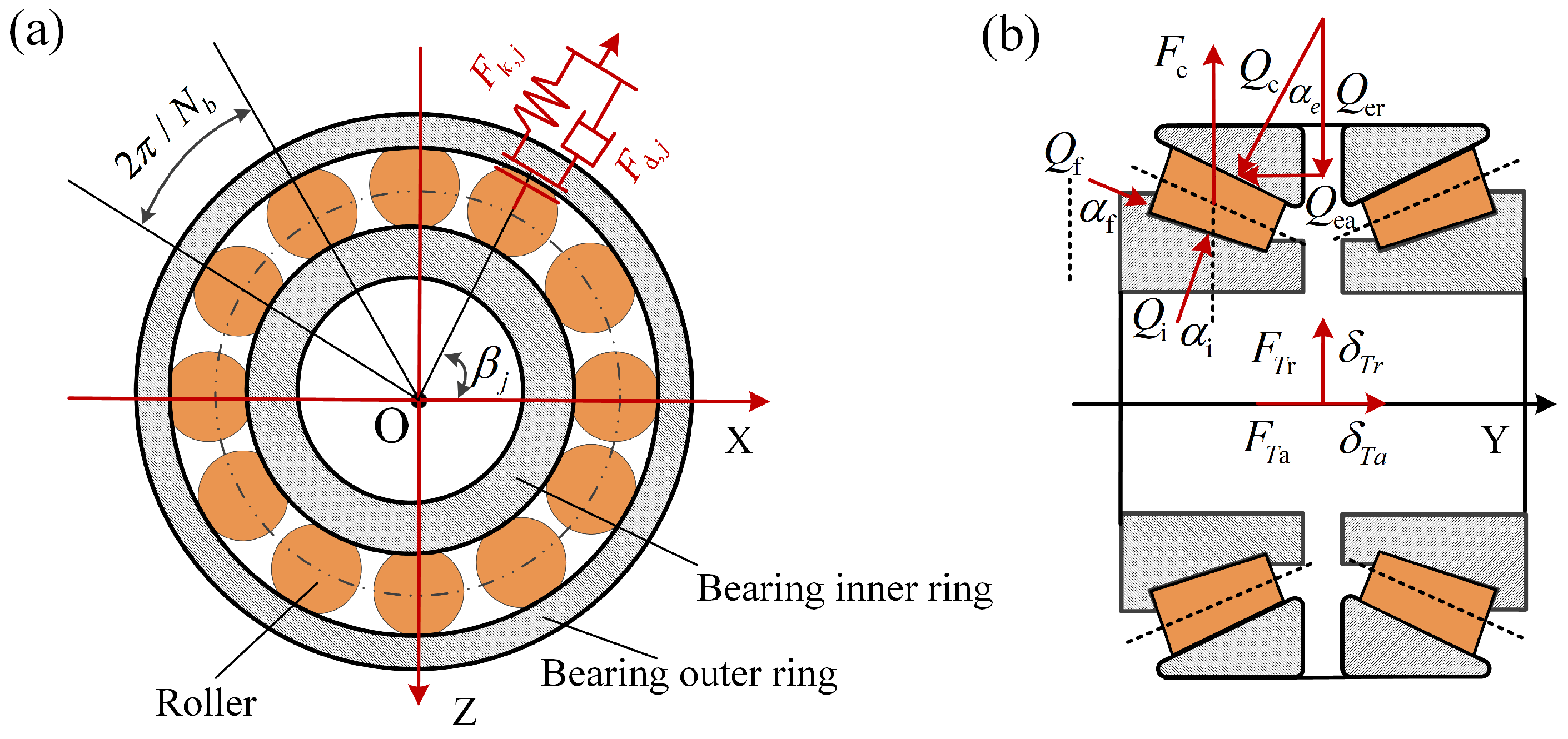
Figure 3 illustrates the axlebox bearing model, where the intricate dynamic interplay between the roller and the raceways is meticulously conceptualized, drawing inspiration from the Hertzian contact theory. In this representation, the rollers and inner raceways amalgamate into a cohesive whole-body entity. The dynamic forces governing the interaction between the rollers and the outer raceway find quantification through the following expression [58]:
where m is the row number, represents the effective contact length of the rollers, and is the compression, m and j represent the index for each row of rollers and the index for each individual rolling element within a row.
The force between the roller and the inner raceway:
where , , and are the contact angles of the roller–inner raceway, roller–outer raceway, and roller–guiding flange, respectively (Figure 3); is the pitch diameter of the tapper roller bearing; and is the orbital angular speed of the rollers obtained by
where is the angular speed of the wheelset and is the mean diameter of the rollers.
The compression of the roller at the azimuthal location can be calculated by
where and are the relative radial and axial displacements between the inner and outer raceways, respectively, which are obtained by
where and are the longitudinal displacements of axlebox and wheelset, respectively; and are the roll and yaw motions of the wheelset, respectively; and are the lateral displacements of the axlebox and wheelset, respectively.
The resultant forces of each axlebox bearing in the radial () and axial () directions can be calculated as follows:
where is the bearing damping.
2.4. Track Irregularity
As mentioned, the track geometry irregularity has a significant impact on axlebox vibration responses on a typical high-speed train. Concerning the irregularities, it is worth mentioning that, in the numerical simulation, there are two distinct types of rail irregularities that have been adopted. The first type consists of the realistic irregularities that have been obtained from the measured high-speed line. On the other hand, the second type is derived from the six different levels of the empirical spectrum of rail irregularities, as documented in reference [58]. It is important that the track irregularity serves as a critical source of track-induced vibration for a railway vehicle. It is not sufficient to simply use a predefined track with a sinusoidal irregularity and a given frequency to investigate the performance of a suspension system or a damper system. Therefore, within the context of this study, a more realistic track model is utilized that closely resembles the level of the measured track irregularities. The method utilized to represent track irregularities in this study is grounded in the power spectrum density (PSD) method developed by the Federal Railway Administration (FRA) of America. This method is grounded on a significant amount of measurement data. With respect to the track irregularity, the power spectrum density (PSD) has been analyzed using even rational functions that include cut-off frequencies and irregularity constants. The wavelengths of these irregularities range from 1.524 to 304.8 m. In general, it should be noted that, apart from the rail irregularities, the wheel–rail interaction differs on each track due to the various combinations of the curve radius, cant deficiency, and transition length. It is important to emphasize that the track design between the high and low rails, specifically the left and right curves, is assumed to be identical throughout the entire simulation process.
In the following simulation, the measured vertical and lateral rail-related irregularities are applied on the left and right rails in this study, as shown in Figure 4.
3. Simulation, Analysis and Discussion
3.1. Conventional Time Domain and Frequency Domain Analysis
In the specified inner and outer ring raceway defect analysis, various defect scenarios are considered, each characterized by specific dimensions and the operational speed of the vehicle. The conditions under investigation include a healthy bearing state, as well as defects with widths of 0.4 mm, 0.6 mm, and 1 mm. In fact, when the early defect of rolling bearing occurs, its area is generally small; therefore, this paper only studies the case where the defect width is smaller than the roller diameter. The simulations are conducted at a constant operating speed of 300 km/h to assess the impact of raceway defects on the performance of the axlebox bearings and overall vehicle dynamics. The vertical vibration of the axlebox (leading bogie, leading wheelset) has been recorded to detect the influences of the targeted inner and outer ring raceway defect for all cases.
In Figure 5a–d, the time domain simulation results offer valuable insights into the dynamic behavior of the coupled vehicle–track system. The time domain results clearly depict the escalating impact of raceway defects as the vehicle accelerates, showing the system’s sensitivity to this fault. A comparative analysis was conducted on the vibration spectrum amplitude RMS values corresponding to inner ring raceway defects of varying sizes, including 0 mm (healthy), 0.4 mm, 0.6 mm, and 1 mm. The results exhibited an increasing trend in RMS values commensurate with the enlargement of the defect size. Specifically, the recorded RMS values were 23.34, 24.9, 25.08, and 26.37 for the respective defect sizes. However, relying on a conventional time domain analysis proves challenging when dealing with intricate faults like inner ring raceway defects. The varying amplitudes of the vibration, influenced by changing external conditions, add complexity to the fault detection process.
Moving beyond a conventional analysis, Figure 6 introduces the axlebox vibration response spectrum at a different inner ring raceway defect at the speed of 300 km/h. The ring raceway defect induces a significant response in the axlebox frequency, particularly at high running speeds. A simplistic spectrum analysis reveals the limitations of insufficient resolution, vibration sensitivity, and a lack of diagnostic information in its fault detection capability. To overcome the above-mentioned limitations and enhance diagnostic accuracy, a more advanced analytical approach is imperative. Advanced signal processing techniques and sophisticated algorithms can be employed to decipher complex fault features and provide a more comprehensive understanding of the system’s health. This multi-faceted approach ensures a thorough exploration of the coupled vehicle–track dynamics, paving the way for improved fault detection and diagnostic capabilities in high-speed train systems.
As shown in Figure 7, with a focus on a 1 mm inner and outer ring raceway defect, it becomes evident that both signals exhibit significantly augmented impulsiveness and substantially surpass the kurtosis levels observed in the healthy signal (defect: 0 mm). The heightened kurtosis values in the signals emanating from the inner and outer ring raceway defects serve as indicative markers of anomalies. This analytical approach not only facilitates a comprehensive comprehension of the observed phenomena but also enhances the precision in identifying specific track irregularities within the vehicle–track model.
3.2. Envelope Analysis
In enhancing the vibration-based detection methodology for high-speed trains afflicted with inner and outer ring raceway defects, we introduce and employ an envelope analysis. This technique is deployed to extract the modulated signal embedded within an amplitude-modulated signal, thereby refining our ability to discern intricate patterns and subtle variations in the system dynamics. The application of an envelope analysis serves as a pivotal advancement in refining the sensitivity and precision of our detection capabilities, thereby contributing to a more robust and effective diagnostic approach for identifying and characterizing faults in the inner and outer ring raceways.
The envelope analysis involves a three-stage process, demonstrating a systematic approach to signal enhancement. Firstly, the application of a band-pass filter is employed for signal filtering. Subsequently, the Hilbert transform method is utilized for the extraction of the signal envelope from the filtered data. The Hilbert transform method serves a pivotal function in simplifying the convolution of the input signal, x(t), employing the generalized impulse function 1/πt. The Hilbert transform method, which is used to extract the filtered vibration signal, can be expressed as follows:
In the third stage, the enveloped signal undergoes a frequency spectrum extraction, achieved through the implementation of the Fast Fourier Transform (FFT) method.
The integration of distinct stages in this approach presents a novel and holistic methodology. This fusion incorporates signal filtering, envelope extraction, and frequency spectrum analysis, synergizing to significantly elevate the accuracy and effectiveness of the envelope analysis. Through this integrated process, a deeper comprehension of the intricate modulations within vibration signals is achieved, showcasing a significant leap forward in diagnostic capabilities. Specifically, it plays a pivotal role in discerning and characterizing faults within high-speed train axlebox bearings, particularly those exhibiting inner and outer ring raceway defects. This method avoids redundancy by not reiterating previous assessments, but rather delving into the method’s adaptability across varying fault complexities and the potential for real-time monitoring in practical scenarios.
The axlebox sensor captures a sequence of vibration responses primarily reflecting the influence of inner and outer raceway defects. In the subsequent analysis, an envelope analysis is employed to discern recurring impacts at characteristic frequencies from these vibration responses.
The application of an envelope analysis to scrutinize the vibration signal results in the presentation of the corresponding normalized envelope spectrum, as illustrated in Figure 8a–e and Figure 9a–e. A comparative examination with the findings from the time domain and frequency domain analysis in Section 3.1 reveals the effectiveness of the envelope analysis in detecting the characteristic frequencies and harmonic features associated with high-speed trains experiencing inner/outer ring raceway defects. Furthermore, the characteristic frequencies corresponding to defect sizes are detailed at the bottom of Figure 8e and Figure 9e. This multi-faceted approach, incorporating the Hilbert transform method and an envelope analysis, showcases an advanced methodology for characterizing and identifying specific vibration patterns associated with the impacts of ring raceway defects on high-speed trains. The integration of these techniques contributes to a comprehensive understanding of the dynamic response of the axlebox sensor and enhances the diagnostic capabilities for potential faults in the axlebox bearings.
4. Conclusions
A highly advanced model that integrates the dynamics of a coupled vehicle and track system has been developed. This model considers the influence of both the traction–gear transmission system and the track system, making it highly comprehensive and accurate. The primary focus of this study is centered around the detection of inner/outer ring raceway defects in high-speed trains using vibration-based techniques. Initially, conventional signal processing techniques, such as time domain and frequency domain techniques, had been employed to analyze the vertical vibration signal of the axlebox; however, it was found to be challenging to accurately characterize ring raceway defects using these techniques alone. As a result, further analyses were conducted, leading to the proposal of utilizing a developed envelope analysis for fault detection in the axlebox vibration signal caused by ring raceway defects. The obtained results indicate that the envelope analysis exhibits a high level of efficiency and reliability in detecting and identifying ring raceway defects. By applying the Fast Fourier Transform (FFT) method to the enveloped signal, the characteristic frequencies and their harmonics can be clearly identified. However, limitations exist within this analysis. While the envelope analysis and FFT method exhibit effectiveness in detecting these faults, their robustness may vary in regard to signal complexities and fault severity levels. Additionally, challenges may arise in differentiating these raceway defects from other bearing-fault types, warranting further research and refinement to augment the method’s adaptability and effectiveness across diverse fault scenarios in bearing analysis.
The outlined future research direction focuses on refining detection methods for inner/outer ring raceway defects in high-speed trains using advanced signal processing techniques like the envelope analysis and Fast Fourier Transform (FFT) method to bolster accuracy and reliability in identifying axlebox vibration signals. Additionally, by improving fault-detection precision, this study serves as a roadmap for further investigations. Future research aims to assess the effectiveness of experimental measurements and expand fault detection capabilities to encompass various other bearing faults, further enhancing the understanding and applicability of fault detection methodologies in the domain of axlebox fault detection in high-speed trains.
Author Contributions
C.L.: Conceptualization, Methodology, Modelling, Analysis, and Writing. X.Z., Q.G. and J.L.: Reviewing and Editing. R.W. and X.Z.: Revising and Editing. All authors have read and agreed to the published version of the manuscript.
Funding
This research was funded by Natural Science Foundation of Hebei Province (A2023210026).
Institutional Review Board Statement
Ethical review and approval were waived for this study, due to Ethics Committee approval was obtained from the Institutional Ethics Committee of Shijiazhuang Tiedao University to the commencement of the study.
Informed Consent Statement
Informed consent was obtained from all subjects involved in the study.
Data Availability Statement
The data presented in this study are available on request.
Acknowledgments
Shijiazhuang Tiedao University is licensed by Dassault Systems Deutschland GmbH to use the SIMPACK 2021. The authors gratefully acknowledge the Shijiazhuang Tiedao University thanks the support of North China University of Science and Technology and Huitong Construction Group Co., Ltd. (China).
Conflicts of Interest
Xinwen Zhang was employed by the company Huitong Construction Group Co., Ltd. The remaining authors declare that the research was conducted in the absence of any commercial or financial relationships that could be construed as a potential conflict of interest.
References
- Yang, S.P.; Gu, X.H.; Liu, Y.Q.; Deng, F.; Liu, Z.; Liu, W.; Wang, B. A Review of Dynamic Mechanism and Fault Diagnosis for Key Rotating Components of Bogies. J. Mech. Eng. 2023, 59, 225–243. [Google Scholar]
- Zhou, J.; Fang, C.C.; Zhang, J.; Zhou, W.; Guan, Y.; Zhang, G. Numerical analysis for typical fault characteristics of high speed train axle box bearing. J. Cent. South Univ. (Nat. Sci. Ed.) 2023, 54, 365–377. [Google Scholar]
- Job, R. Railway bearings: An investigation of causes of hot boxes in railway service, and methods for their prevention. J. Frankl. Inst. 1900, 149, 439–450. [Google Scholar] [CrossRef]
- SKF Group. Bearing investigation. In Railway Technical Handbook; SKF: Gothenburg, Sweden, 2012; pp. 122–135. [Google Scholar]
- SKF Group. Bearing Damage and Failure Analysis; SKF Explorer: Gothenburg, Sweden, 2014. [Google Scholar]
- Zrestsky, E.V. Rolling Bearing Life Prediction, Theory, and Application; Glen Research Centre—NASA: Cleveland, OH, USA, 2013. [Google Scholar]
- Yao, T.Q.; Wang, L.H.; Liu, X.B.; Huang, Y. Multibody dynamics simulation of thin-walled four-point contact ball bearing with interactions of balls, ring raceways and crown-type cage. Multibody Syst. Dyn. 2020, 48, 337–372. [Google Scholar] [CrossRef]
- Stribeckr. Ball bearings for various loads. Trans. ASME 1907, 29, 420–463. [Google Scholar]
- Waltersc, T. The dynamics of ball bearings. J. Lubr. Technol. 1971, 93, 1–10. [Google Scholar] [CrossRef]
- Tadina, M.; Boltežar, M. Improved model of a ball bearing for the simulation of vibration signals due to faults during Run-up. J. Sound Vib. 2011, 330, 4287–4301. [Google Scholar] [CrossRef]
- Wang, Z.W.; Song, Y.; Yin, Z.H.; Wang, R.; Zhang, W. Random response analysis of axle-box bearing of high-speed train excited by crosswinds and track irregularities. IEEE Trans. Veh. Technol. 2019, 68, 10607–10617. [Google Scholar] [CrossRef]
- Cha, H.; Ren, Z.S.; Xu, N. Load Characteristics of Axle Box Bearing Raceway of High-speed EMU. J. Mech. Eng. 2020, 56, 135–142. [Google Scholar]
- Liao, X.; Yi, C.; Zhang, Y.; Chen, Z.; Ou, F.; Lin, J. A simulation investigation on the effect of wheel-polygonal wear on dynamic vibration characteristics of the axle-box system. Eng. Fail. Anal. 2022, 139, 106–513. [Google Scholar] [CrossRef]
- Wang, Z.; Zhang, W.; Yin, Z.; Cheng, Y.; Huang, G.; Zou, H. Effect of vehicle vibration environment of high-speed train on dynamic performance of axle box bearing. Veh. Syst. Dyn. 2019, 57, 543–563. [Google Scholar] [CrossRef]
- Huang, N.E.; Shen, Z.; Long, S.R.; Wu, M.C.; Shih, H.H.; Zheng, Q.; Yen, N.C.; Tung, C.C.; Liu, H.H. The empirical mode decomposition and the Hilbert spectrum for nonlinear and non-stationary time series analysis. Proc. R. Soc. Lond. Ser. A Math. Phys. Eng. Sci. 1998, 454, 903–995. [Google Scholar] [CrossRef]
- Morlet, J.; Arens, G.; Fourgeau, E.; Giard, D. Wave propagation and sampling theory—Part II: Sampling theory and complex waves. Geophysics 1982, 47, 222–236. [Google Scholar] [CrossRef]
- Sun, Y.J.; Li, S.H.; Wang, X.H. Bearing fault diagnosis based on EMD and improved Chebyshev distance in SDP image. Measurement 2021, 176, 109100. [Google Scholar] [CrossRef]
- Zheng, J.D.; Pan, H.Y. Mean-optimized mode decomposition: An improved EMD approach for nonstationary signal processing. ISA Trans. 2020, 106, 392–401. [Google Scholar] [CrossRef] [PubMed]
- Hu, M.; Wang, G.; Ma, K.; Cao, K.; Yang, S. Bearing performance degradation assessment based on optimized EWT and CNN. Measurement 2021, 172, 108868. [Google Scholar] [CrossRef]
- Wan, S.T.; Zhang, X.; Du, L.J. Separation of composite rolling bearings fault features with strong noise interference. J. Cent. South Univ. (Nat. Sci. Ed.) 2018, 49, 1950–1959. [Google Scholar]
- Dong, J.X.; Song, D.L.; Li, L.; Liu, Y.; Deng, C.; Chen, Z. Application of parameter adaptive VMD in fault diagnosis of axle box bearing of high-speed train. J. Cent. South Univ. (Nat. Sci. Ed.) 2023, 54, 1344–1357. [Google Scholar]
- Zhang, Q.S.; Ding, J.M.; Zhao, W.T. An adaptive boundary determination method for empirical wavelet transform and its application in wheelset-bearing fault detection in high-speed trains. Measurement 2021, 171, 108746. [Google Scholar] [CrossRef]
- Ding, J.M. A double impulsiveness measurement indices-bilaterally driven empirical wavelet transform and its application to wheelset-bearing-system compound fault detection. Measurement 2021, 175, 109135. [Google Scholar] [CrossRef]
- Palmgren, A. Ball and Roller Bearing Engineering; S.H. Burbank: Philadelphia, PA, USA, 1959. [Google Scholar]
- Harris, T.A.; Mindel, M.H. Rolling element bearing dynamics. Wear 1973, 23, 311–337. [Google Scholar] [CrossRef]
- Pouly, F.; Changenet, C.; Ville, F. Investigations on the power losses and thermal behaviour of rolling element bearings. Proc. Inst. Mech. Eng. Part J J. Eng. Tribol. 2010, 224, 925–933. [Google Scholar] [CrossRef]
- Wang, L.; Chen, G.; Gu, L. The operation temperature study of the high speed cylindrical rolling bearing. J. Aerosp. Power 2008, 23, 179–183. [Google Scholar]
- Zhou, X.; Zhang, H.; Hao, X.; Liao, X.; Han, Q. Investigation on thermal behavior and temperature distribution of bearing inner and outer rings. Tribol. Int. 2019, 130, 289–298. [Google Scholar] [CrossRef]
- Wang, T.; Wang, Z.; Song, D.; Zhang, W.; Li, J.; Chen, D. Effect of track irregularities of high-speed railways on the thermal characteristics of the traction motor bearing. Proc. Inst. Mech. Eng. Part F J. Rail Rapid Transit 2021, 235, 22–34. [Google Scholar] [CrossRef]
- Gao, P.; Hou, L.; Chen, Y.Z. Dynamic Load of the Inter-Shaft Bearing and Its Influence on Bearing’s Temperature. J. Mech. Eng. 2022, 58, 87–97. [Google Scholar]
- Mitrović, R.M.; Atanasovska, I.D.; Soldat, N.D.; Soldat, N.D. Effects of operation temperature on thermal expansion and main parameters of radial ball bearings. Therm. Sci. 2015, 19, 1835–1844. [Google Scholar] [CrossRef]
- Hao, X.; Li, N.; Yu, C.X.; Zhai, J. Characterisation of displacement and raceway stresses in cylindrical roller bearings with inner and outer rings considering thermal effects. J. Mech. Eng. 2022, 58, 151–160. [Google Scholar]
- Immovilli, F.; Bianchini, C.; Cocconcelli, M.; Bellini, A.; Rubini, R. Bearing Fault Model for Induction Motor with Externally Induced Vibration. IEEE Trans. Ind. Electron. 2012, 60, 3408–3418. [Google Scholar] [CrossRef]
- Kim, T.-J.; Hwang, S.-M.; Kim, K.-T.; Jung, W.-B.; Kim, C.-U. Comparison of dynamic responses for IPM and SPM motors by considering mechanical and magnetic coupling. IEEE Trans. Magn. 2001, 37, 2818–2820. [Google Scholar]
- Bai, X.; Zhang, Z.; Shi, H.; Luo, Z.; Li, T. Identification of Subsurface Mesoscale Crack in Full Ceramic Ball Bearings Based on Strain Energy Theory. Appl. Sci. 2023, 13, 7783. [Google Scholar] [CrossRef]
- Saucedo-Dorantes, J.J.; Arellano-Espitia, F.; Delgado-Prieto, M.; Osornio-Rios, R.A. Diagnosis Methodology Based on Deep Feature Learning for Fault Identification in Metallic, Hybrid and Ceramic Bearings. Sensors 2021, 21, 5832. [Google Scholar] [CrossRef]
- Shi, H.; Hou, M.; Wu, Y.; Li, B. Incipient Fault Detection of Full Ceramic Ball Bearing Based on Modified Observer. Int. J. Control Autom. Syst. 2022, 20, 727–740. [Google Scholar] [CrossRef]
- Li, B.; Chow, M.-Y.; Tipsuwan, Y.; Hung, J. Neural-network-based motor rolling bearing fault diagnosis. IEEE Trans. Ind. Electron. 2000, 47, 1060–1069. [Google Scholar] [CrossRef]
- Kang, M.; Kim, J.; Wills, L.M.; Kim, J.-M. Time-Varying and Multiresolution Envelope Analysis and Discriminative Feature Analysis for Bearing Fault Diagnosis. IEEE Trans. Ind. Electron. 2015, 62, 7749–7761. [Google Scholar] [CrossRef]
- Mbo’o, C.P.; Hameyer, K. Fault diagnosis of bearing damage by means of the linear discriminant analysis of stator current features from the frequency selection. IEEE Trans. Ind. Appl. 2016, 52, 3861–3868. [Google Scholar] [CrossRef]
- Yang, L.; Xu, T.; Xu, H.; Wu, Y. Mechanical behavior of double-row tapered roller bearing under combined external loads and angular misalignment. Int. J. Mech. Sci. 2018, 142–143, 561–574. [Google Scholar] [CrossRef]
- Andréason, S. Load distribution in a taper roller bearing arrangement considering misalignment. Tribology 1973, 6, 84–92. [Google Scholar] [CrossRef]
- Bercea, I.; Cretu, S.; Nélias, D. Analysis of double-row tapered roller bearings, Part I-Model. Tribol. Trans. 2003, 46, 228–239. [Google Scholar] [CrossRef]
- Nelias, D.; Bercea, I.; Mitu, N. Analysis of double-row tapered roller bearings, Part II–results: Prediction of fatigue life and heat dissipation. Tribol. Trans. 2003, 46, 240–247. [Google Scholar] [CrossRef]
- Kabus, S.; Hansen, M.R.; Mouritsen, O. A new quasi-static multidegree of freedom tapered roller bearing model to accurately consider non-Hertzian contact pressures in time-domain simulations. Proc. Inst. Mech. Eng. Part K J. Multi-Body Dyn. 2014, 228, 111–125. [Google Scholar]
- Tong, V.-C.; Hong, S.-W. The effect of angular misalignment on the running torques of tapered roller bearings. Tribol. Int. 2016, 95, 76–85. [Google Scholar] [CrossRef]
- Tong, V.-C.; Hong, S.-W. Characteristics of tapered roller bearing with geometric error. Int. J. Precis. Eng. Manuf. 2015, 16, 2709–2716. [Google Scholar] [CrossRef]
- Houser, D.R.; Drosjack, M.J. Vibration Signal Analysis Techniques; National Technical Information Service, US Department of Commerce: Columbus, OH, USA, 1973. [Google Scholar]
- Butler, D. The Shock-pulse method for the detection of damaged rolling bearings. Non-Destr. Test. 1973, 6, 92–95. [Google Scholar] [CrossRef]
- Gupta, P.K. Dynamics of Rolling-Element Bearings—Part I: Cylindrical Roller Bearing Analysis. J. Lubr. Technol. 1979, 101, 293–302. [Google Scholar] [CrossRef]
- Gupta, P.K. Dynamics of rolling-element bearings—Part II: Cylindrical roller bearing analysis. J. Lubr. Technol. 1979, 101, 305–311. [Google Scholar] [CrossRef]
- Lu, Z.; Wang, X.; Yue, K.; Wei, J.; Yang, Z. Coupling model and vibration simulations of railway vehicles and running gear bearings with multitype defects. Mech. Mach. Theory 2020, 157, 104215. [Google Scholar] [CrossRef]
- McFadden, P.; Smith, J. Model for the vibration produced by a single point defect in a rolling element bearing. J. Sound Vib. 1984, 96, 69–82. [Google Scholar] [CrossRef]
- McFadden, P.; Smith, J. The vibration produced by multiple point defects in a rolling element bearing. J. Sound Vib. 1985, 98, 263–273. [Google Scholar] [CrossRef]
- GmbH. Multi-Body Simulation. SIMPACK MBS Software. Available online: http://www.simpack.com/ (accessed on 1 August 2023).
- Wang, Z.; Mei, G.; Xiong, Q.; Yin, Z.; Zhang, W. Motor car–track spatial coupled dynamics model of a high-speed train with traction transmission systems. Mech. Mach. Theory 2019, 137, 386–403. [Google Scholar] [CrossRef]
- Zhai, W.; Wang, K.; Cai, C. Fundamentals of vehicle–track coupled dynamics. Veh. Syst. Dyn. 2009, 47, 1349–1376. [Google Scholar] [CrossRef]
- Zhai, W. Vehicle—Track Coupled Dynamics; Springer: Singapore, 2020; ISBN 978-981-329-283-3. [Google Scholar]
Figure 1.
Vehicle–track coupled dynamics model in elevation views.

Figure 2.
Top view of vehicle–track coupled dynamic model.

Figure 3.
A simplified view of axlebox bearings of a high-speed train: (a) side view and (b) cutout view.
Figure 3.
A simplified view of axlebox bearings of a high-speed train: (a) side view and (b) cutout view.

Figure 4.
The track irregularities used to railway line in the later al and vertical directions.

Figure 5.
Time domain of vertical axlebox vibration signals at the speed of 300 km/h.

Figure 6.
Frequency spectrum of vibration signals at the speed of 300 km/h.

Figure 7.
Acceleration and kurtosis of inner and outer ring raceway defect at 1 mm and healthy conditions.
Figure 7.
Acceleration and kurtosis of inner and outer ring raceway defect at 1 mm and healthy conditions.

Figure 8.
Filtered envelope analysis at different inner ring raceway defect.

Figure 9.
Filtered envelope analysis at different outer ring raceway defect.


Table 1.
Key components and motions of the vehicle model.
| Key Components | Longitudinal | Lateral | Vertical | Roll | Yaw | Pitch |
|---|---|---|---|---|---|---|
| Carbody (Only one) | ||||||
| bogie (i = 1, 2) | ||||||
| Traction motor (i = 1–4) | — | — | ||||
| Gearbox (i = 1–4) | — | — | ||||
| Pinion (i = 1–4) | — | |||||
| Wheelset (i = 1–4) |
Disclaimer/Publisher’s Note: The statements, opinions and data contained in all publications are solely those of the individual author(s) and contributor(s) and not of MDPI and/or the editor(s). MDPI and/or the editor(s) disclaim responsibility for any injury to people or property resulting from any ideas, methods, instructions or products referred to in the content. |
© 2024 by the authors. Licensee MDPI, Basel, Switzerland. This article is an open access article distributed under the terms and conditions of the Creative Commons Attribution (CC BY) license (https://creativecommons.org/licenses/by/4.0/).
Share and Cite
MDPI and ACS Style
Liu, C.; Zhang, X.; Wang, R.; Guo, Q.; Li, J. Vibration-Based Detection of Axlebox Bearing Considering Inner and Outer Ring Raceway Defects. Lubricants 2024, 12, 142. https://doi.org/10.3390/lubricants12050142
AMA Style
Liu C, Zhang X, Wang R, Guo Q, Li J. Vibration-Based Detection of Axlebox Bearing Considering Inner and Outer Ring Raceway Defects. Lubricants. 2024; 12(5):142. https://doi.org/10.3390/lubricants12050142
Chicago/Turabian StyleLiu, Chuang, Xinwen Zhang, Ruichen Wang, Qiang Guo, and Junguo Li. 2024. "Vibration-Based Detection of Axlebox Bearing Considering Inner and Outer Ring Raceway Defects" Lubricants 12, no. 5: 142. https://doi.org/10.3390/lubricants12050142
Note that from the first issue of 2016, this journal uses article numbers instead of page numbers. See further details here.