
The Friction Reducing Effect of Square-Shaped Surface Textures under Lubricated Line-Contacts—An Experimental Study


Abstract
:
1. Introduction
2. Experimental Details
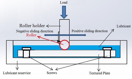
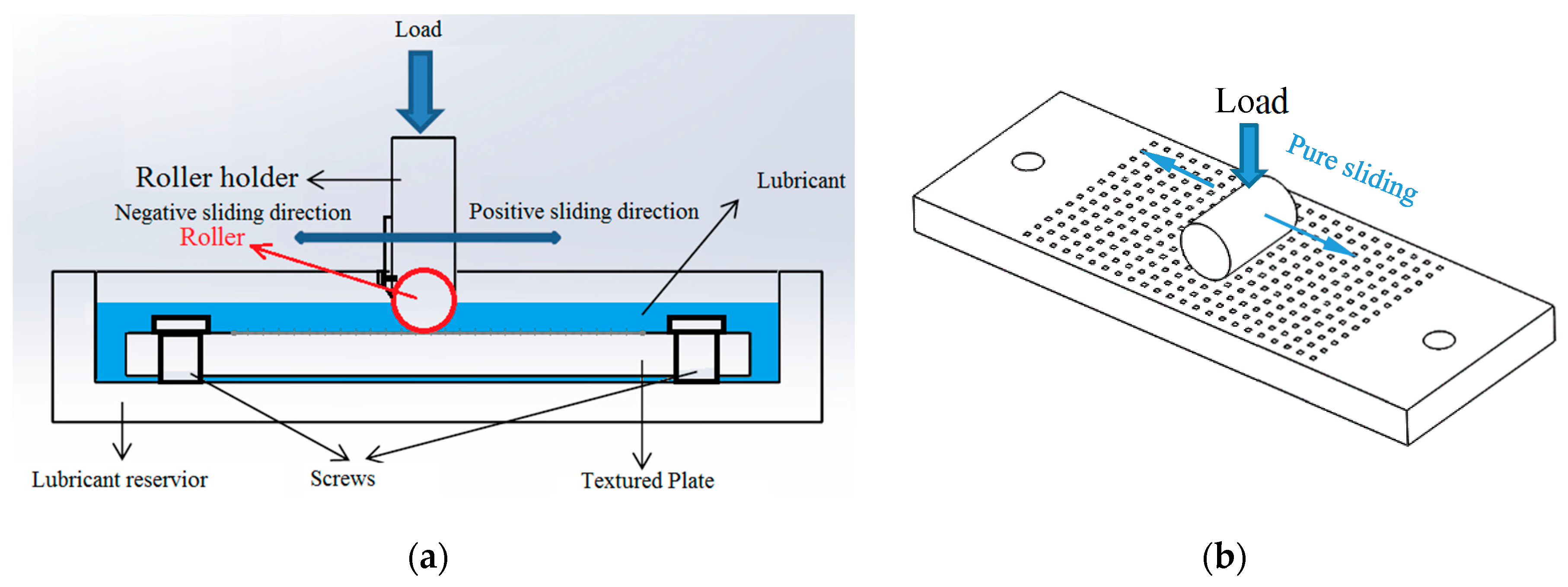
2.1. The Test Rig
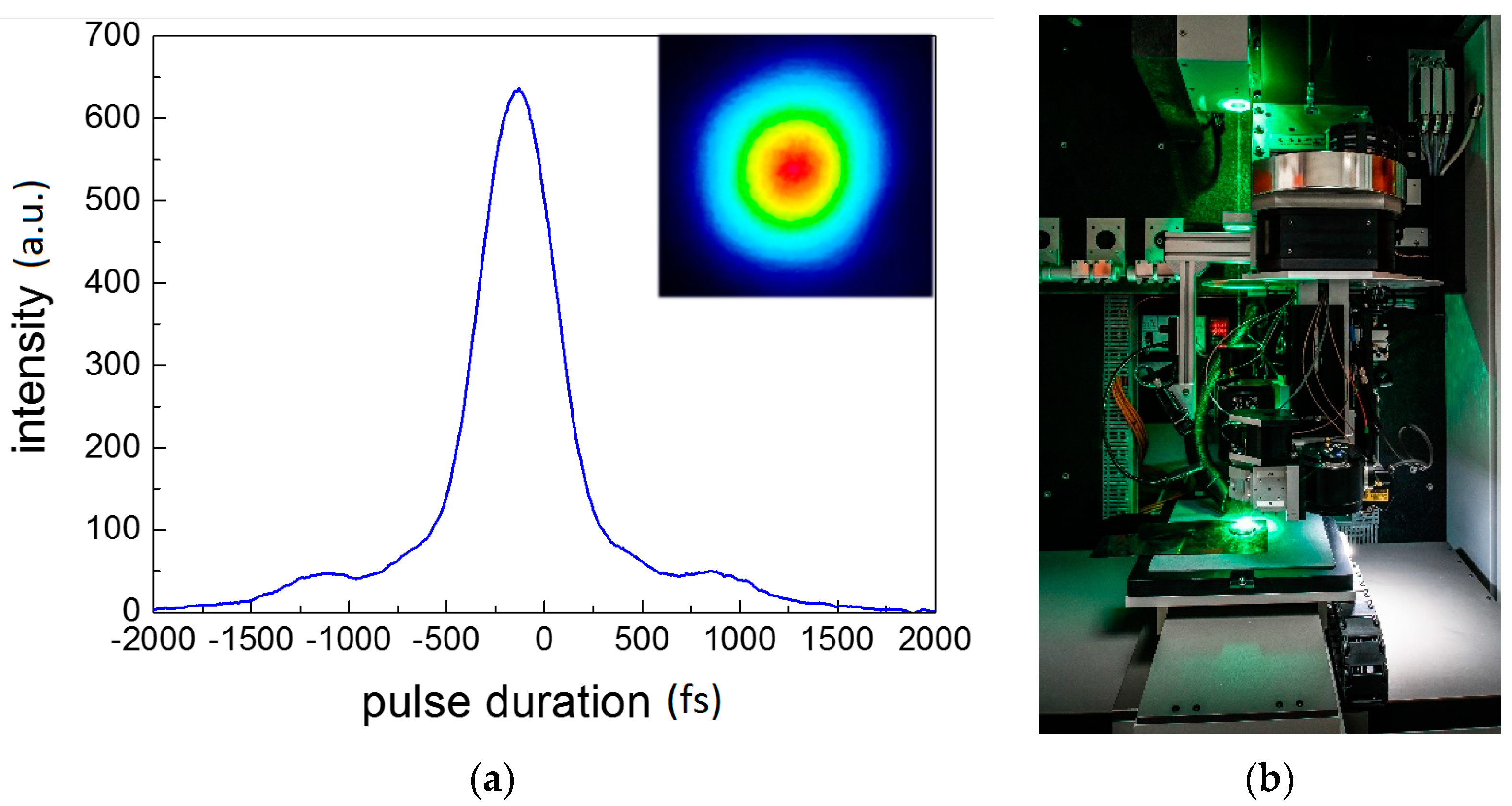
2.2. Materials and Test Sample Preparation
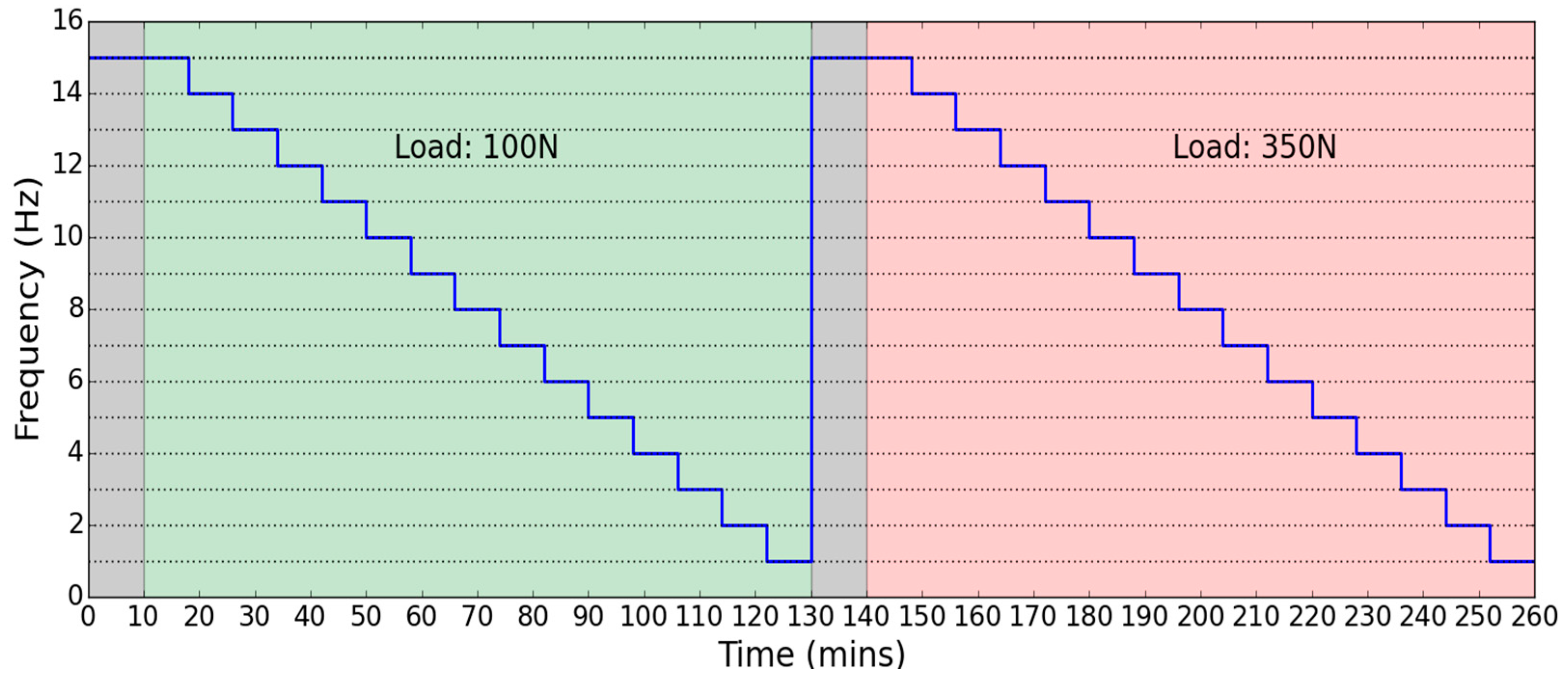
2.3. Experimental Procedures
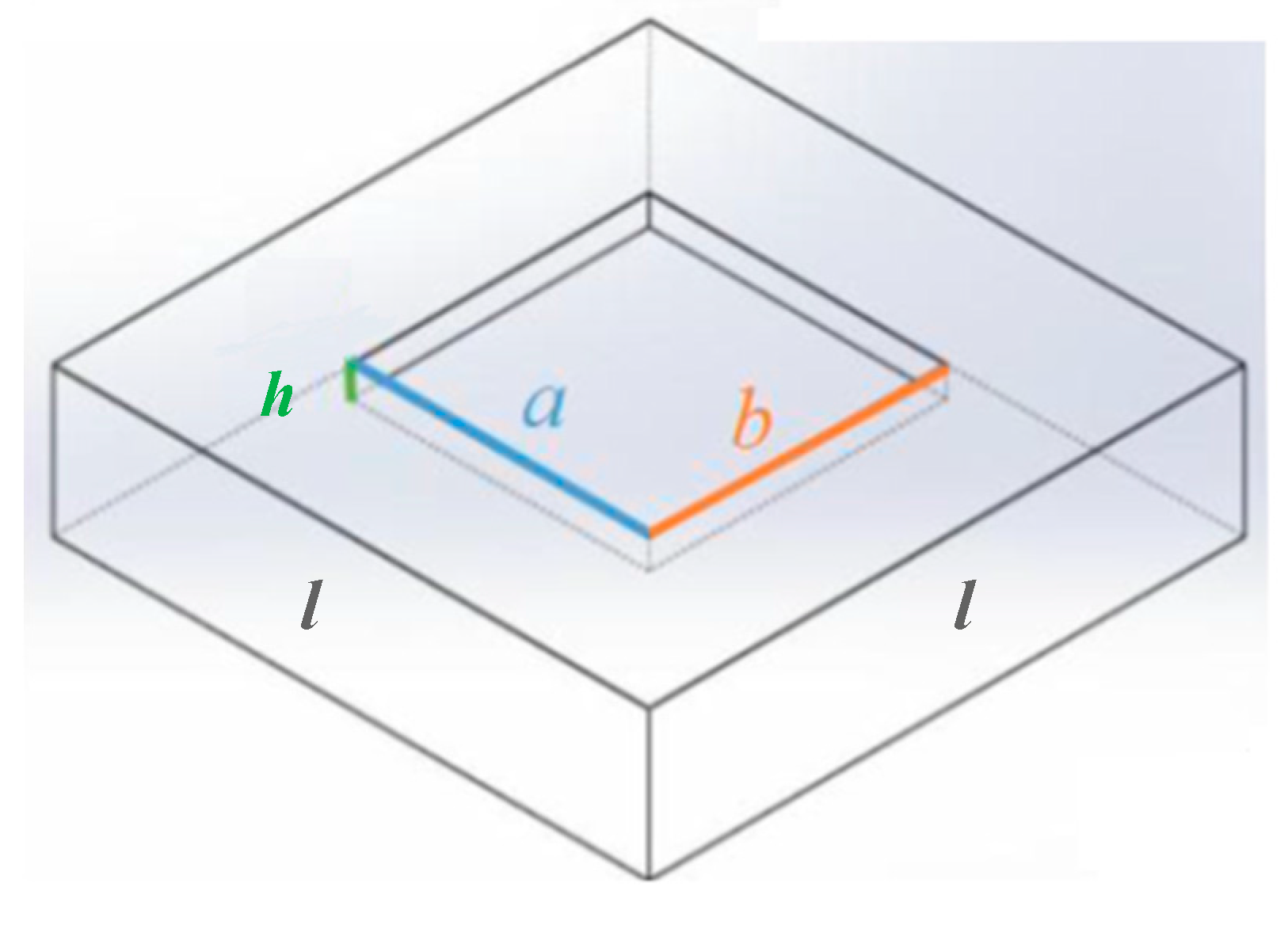
2.4. Sample Parameter
3. Results and Discussion
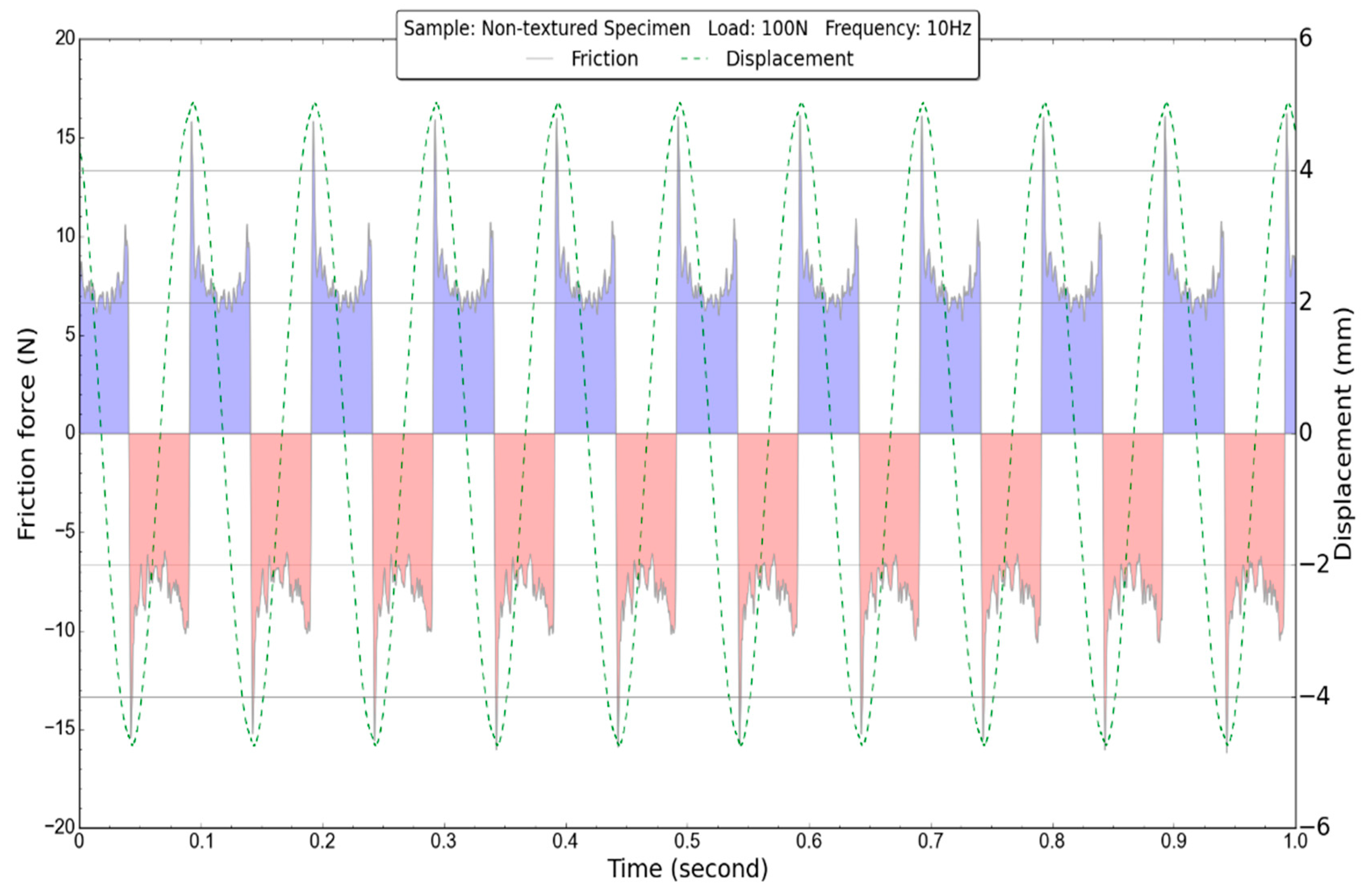
3.1. Friction Force Stability versus Time
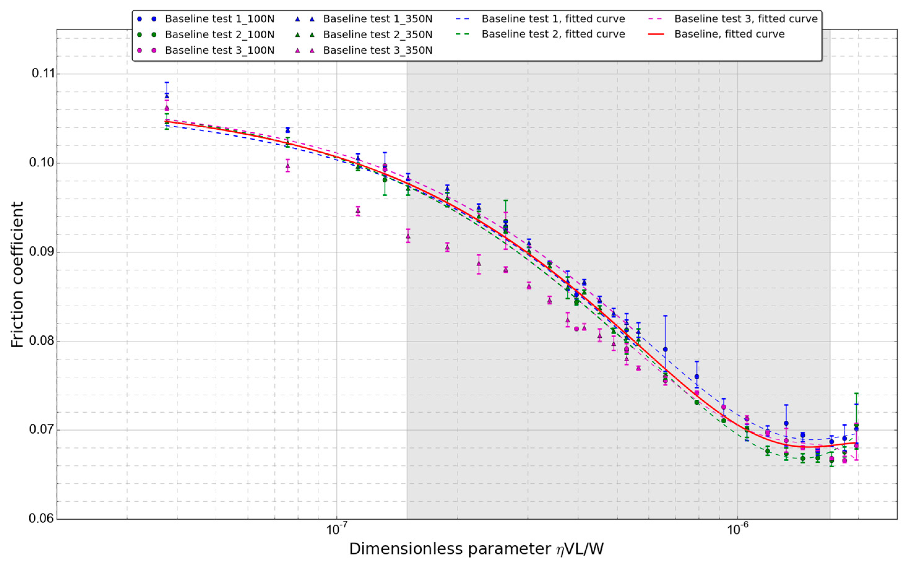
3.2. Baseline Results
3.3. Textured Surfaces Results
4. Conclusions
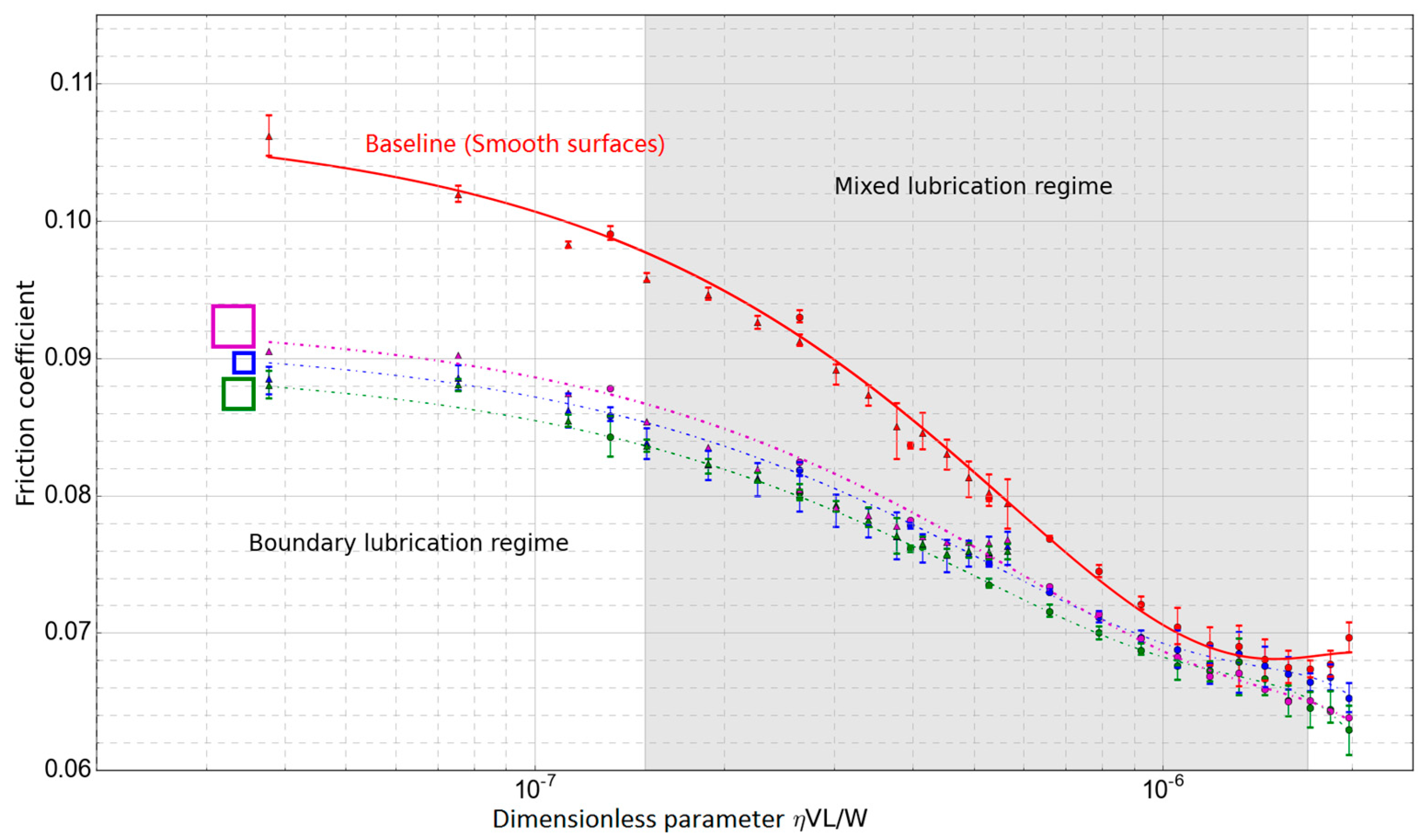
- From the Stribeck curve analysis, all the textured samples have a lower friction coefficient compared to the non-textured samples in the boundary lubrication regime. This effect is attributed to the dimples working as lubricant reservoirs. The lubricant will be squeezed out of the dimple when the roller pressing the dimpled surface, which was called secondary lubrication. This phenomenon happened when solid surfaces were partly in contact.
- Among all the flat bottom dimple tests, no obvious differences were found between dimples with different sizes, which maybe because the contact width is much smaller than the dimple size, and dimples were not fully covered by the Hertzian contact area. Therefore, the size influence is not obvious under the current test conditions.
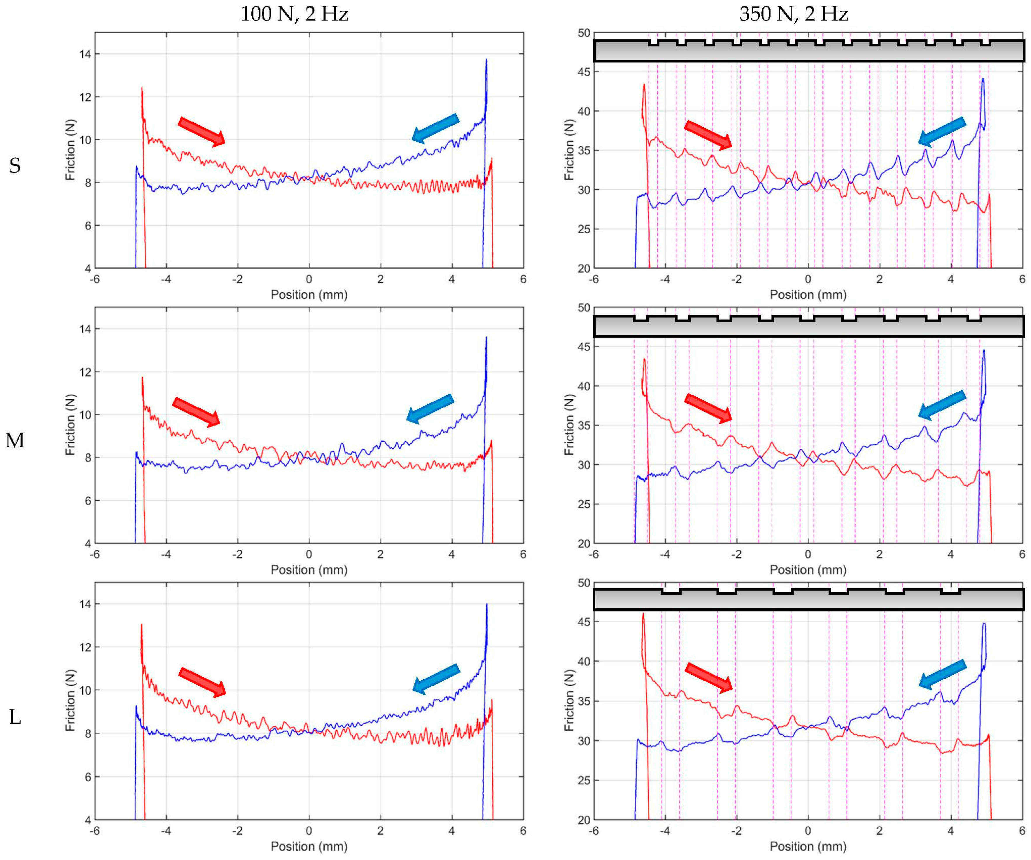
- From the low load single stroke analysis, it is observed the friction may decrease when the reversal point locates on the dimples, and it can be deducted that the textures at reversal point can help building the oil film to reduce the starting friction.
- From the single stroke analysis under high load test conditions, the friction decrease in the leading edge indicates that, dimples on the surface work as lubricant reservoirs under high load test conditions. While the friction increasing in the ending edge indicates that, the micro-hydrodynamic lift from the ending edge may not exist when the dimple size is much larger than the contact width. On the contrary, a specific fluid flow may be affected by ending edges, and the film thickness in the ending edge is thinner than that above the dimpled area.
Acknowledgments
Author Contributions
Conflicts of Interest
References
- Blatter, A.; Maillat, M.; Pimenov, S.M.; Shafeev, G.A.; Simakin, A.V.; Loubnin, E.N. Lubricated sliding performance of laser-patterned sapphire. Wear 1999, 232, 226–230. [Google Scholar] [CrossRef]
- Wang, X.; Kato, K.; Adachi, K.; Aizawa, K. The effect of laser texturing of sic surface on the critical load for the transition of water lubrication mode from hydrodynamic to mixed. Tribol. Int. 2001, 34, 703–711. [Google Scholar] [CrossRef]
- Brizmer, V.; Kligerman, Y.; Etsion, I. A laser surface textured parallel thrust bearing. Tribol. Trans. 2003, 46, 397–403. [Google Scholar] [CrossRef]
- Lu, X.; Khonsari, M.M. An experimental investigation of dimple effect on the stribeck curve of journal bearings. Tribol. Lett. 2007, 27, 169–176. [Google Scholar] [CrossRef]
- Ogihara, H.; Kido, T.; Yamada, H.; Murata, M.; Kobayashi, S. Technology for reducing engine rubbing resistance by means of surface improvement. Honda R&D Tech. Rev. 2000, 12, 93–98. [Google Scholar]
- Bogdan, A. Mechanical seals with sliding surface texture – model fluid flow and some aspects of the laser forming of the texture. Proc. Eng. 2012, 39, 51–62. [Google Scholar]
- Kurella, A.; Dahoptre, N.B. Review paper: Surface modification for bioimplants: The role of laser surface engineering. J. Biomater. Appl. 2005, 20, 5–50. [Google Scholar] [CrossRef] [PubMed]
- Hamilton, D.B.; Walowit, J.A.; Allen, C.M. A theory of lubrication by micro-irregularities. J. Basic Eng. 1966, 88, 177–185. [Google Scholar] [CrossRef]
- Etsion, I.; Halperin, G.; Becker, E. The effect of various surface treatments on piston pin scuffing resistance. Wear 2006, 261, 785–791. [Google Scholar] [CrossRef]
- Wang, X.; Kato, K.; Adachi, K.; Aizawa, K. Loads carrying capacity map for the surface texture design of sic thrust bearing sliding in water. Tribol. Int. 2003, 36, 189–197. [Google Scholar] [CrossRef]
- Qiu, Y.; Khonsari, M.M. Experimental investigation of tribological performance of laser textured stainless steelrings. Tribol. Int. 2011, 44, 635–644. [Google Scholar] [CrossRef]
- Yu, H.; Deng, H.; Huang, W.; Wang, X. The effect of dimple shapes on friction of parallel surfaces. Proc. Inst. Mech. Eng. J J. Eng. Tribol. 2011, 225, 693–703. [Google Scholar] [CrossRef]
- Wang, W.; Huang, Z.; Shen, D.; Kong, L.; Li, S. The effect of triangle-shaped surface textures on the performance of the lubricated point-contacts. J. Tribol. 2013, 135, 1–11. [Google Scholar] [CrossRef]
- Costa, H.L.; Hutchings, I.M. Hydrodynamic lubrication of textured steel surfaces under reciprocating sliding conditions. Tribol. Int. 2007, 40, 1227–1238. [Google Scholar] [CrossRef]
- Vladescu, S.-C.; Olver, A.V.; G.Pegg, I.; Reddyhoff, T. The effects of surface texture in reciprocating contacts - an experimental study. Tribol. Int. 2015, 82, 28–42. [Google Scholar] [CrossRef]
- Shen, C.; Khonsari, M.M. Texture shape optimization for seal-like parallel surfaces: Theory and experiment. Tribol. Trans. 2016. [Google Scholar] [CrossRef]
- Hsu, S.M.; Jing, Y.; Hua, D.; Zhang, H. Friction reduction using discrete surface textures: Principle and design. J. Phys.D Appl. Phys. 2014, 47, 335307. [Google Scholar] [CrossRef]
- Yan, D.; Qu, N.; Li, H.; Wang, X. Significance of dimple parameters on the friction of sliding surfaces investigated by orthogonal experiments. Tribol. Trans. 2010, 53, 703–712. [Google Scholar] [CrossRef]
- Mangang, M.; Seifert, H.J.; Pfleging, W. Influence of laser pulse duration on the electrochemical performance of laser structured lifepo4 composite electrodes. J. Power Sources 2016, 304, 24–32. [Google Scholar] [CrossRef]
- Dowson, D.; Higginson, G.R. Elasto-Hydrodynamic Lubrication: The Fundamentals of Roller and Gear Lubrication; Pergamon Press: Oxford, UK, 1966. [Google Scholar]
- Stachowiak, G.; Batchelor, A.W. Engineering Tribology, 4th ed.; Butterworth-Heinemann: Oxford, UK, 2013. [Google Scholar]
- Johnason, K.L. Contact Mechanics; Cambridge University Press: Cambridge, UK, 1985. [Google Scholar]
- Pettersson, U. Surfaces designed for high and low friction. In Digital Comprehensive Summaries of Uppsala Dissertations from the Faculty of Science and Technology 63; Acta Universitatis Upsaliensis Uppsala, Uppsala Universitet: Uppsala, Sweden, 2005. [Google Scholar]
- Wakuda, M.; Yamauchi, Y.; Kanzaki, S.; Yasuda, Y. Effect of surface texturing on friction reduction between ceramic and steel materials under lubricated sliding contact. Wear 2003, 254, 356–363. [Google Scholar] [CrossRef]
- Vlădescu, S.-C.; Medina, S.; Olver, A.V.; Pegg, I.G.; Reddyhoff, T. The transient friction response of a laser-textured, reciprocating contact to the entrainment of individual pockets. Tribol. Lett. 2016, 62, 12. [Google Scholar] [CrossRef]


| Grade | Density | Elastic Modulus | Hardness | Poisson Ratio |
|---|---|---|---|---|
| Kg/m3 | GPa | Vickers hardness (HV) | ||
| Smooth surface material: AISI 52100 | 7810 | 200 | 848 | 0.28 |
| Textured surface material: ASP 2023 | 8000 | 230 | 800 | 0.29 |
| Density | Kinematic Viscosity | Kinematic Viscosity | Pressure-Viscosity Coefficient |
|---|---|---|---|
| at 15 °C (ρ) | at 40 °C (υ0) | at 100 °C (υ1) | (α) |
| 868 kg/m3 | 32 mm2/s | 5.4 mm2/s | 12.8 × 10⁻⁹ m2/s |
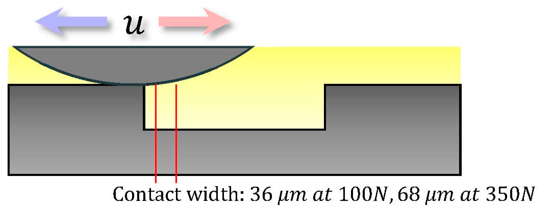
| Load (N) | Contact Width (µm) | Mean Contact Pressure (GPa) | Maximum Contact Pressure (GPa) |
|---|---|---|---|
| 100 N | 36 | 0.28 | 0.35 |
| 350 N | 68 | 0.52 | 0.66 |
| Sample | Side Length | Side Length | Maximum Dimple Depth | Interval Length | Area Density |
|---|---|---|---|---|---|
| No. | (a/µm) | (b/µm) | (hD/µm) | (l/µm) | (cr/%) |
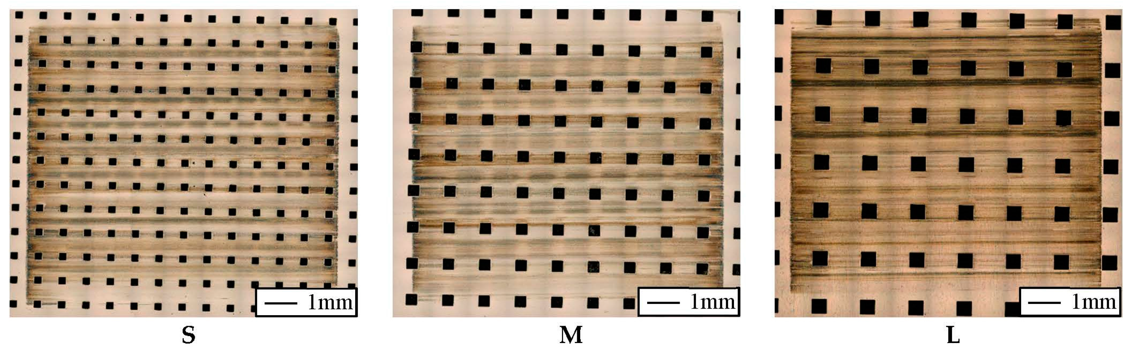
| S | 250 | 250 | 15 | 790 | 10 |
| M | 375 | 375 | 15 | 1185 | 10 |
| L | 500 | 500 | 15 | 1580 | 10 |
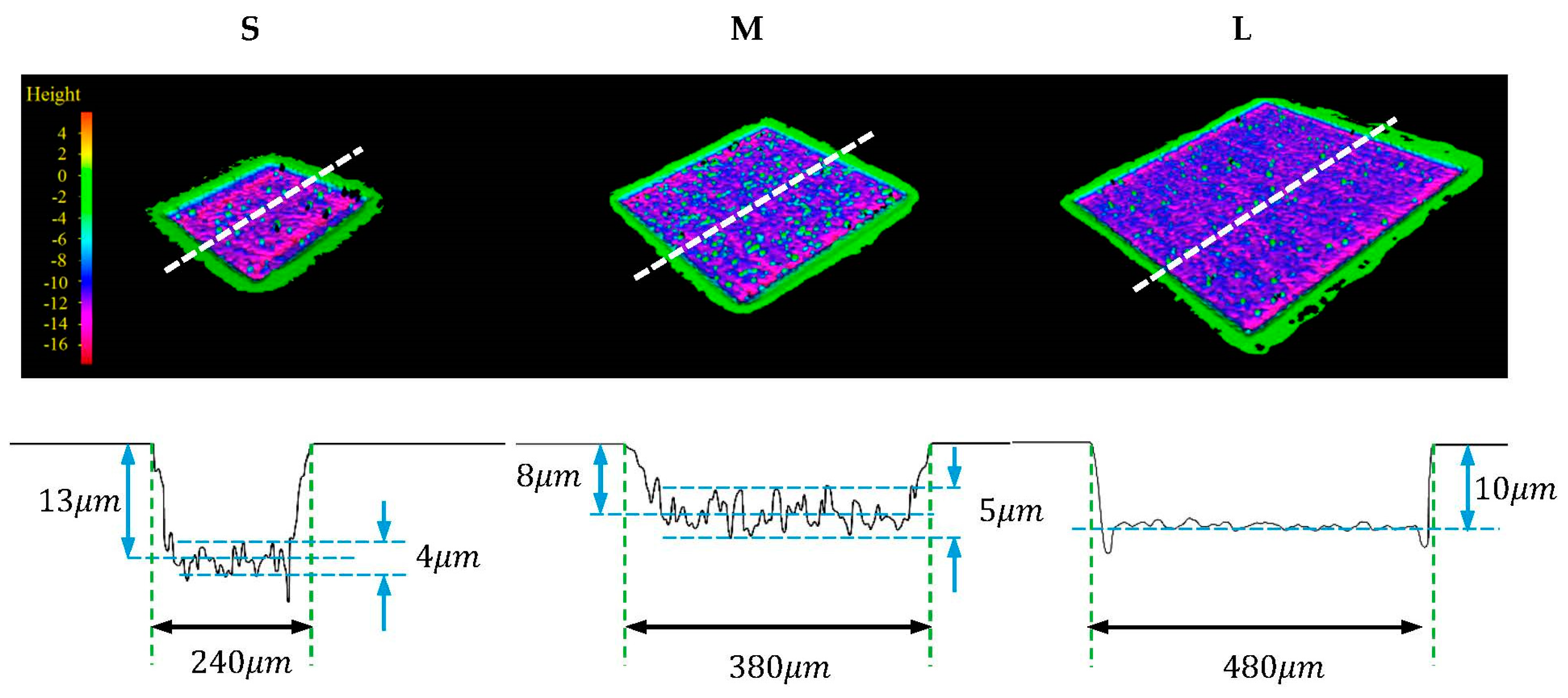
| Sample | Side Length | Side Length | Maximum Dimple Depth | Interval Length | Area Density |
|---|---|---|---|---|---|
| No. | (a/µm) | (b/µm) | (hD/µm) | (l/µm) | (%) |
| S | 240 ± 5 | 240 ± 5 | 13 ± 2 | 790 ± 5 | 9.1 |
| M | 375 ± 5 | 375 ± 5 | 8 ± 3 | 1185 ± 5 | 10.0 |
| L | 480 ± 5 | 480 ± 5 | 10 ± 1 | 1580 ± 5 | 9.2 |
| Sample | Dimple Numbers | First Dimple Position (left) (Left Edge) | Wear Scar Length (Horizontal Direction) | Wear Scar Width (Vertical Direction) |
|---|---|---|---|---|
| No. | (mm) | (µm) | (µm) | |
| S | 13 | −4.460 | 10,194 | 9300 |
| M | 9 | −4.875 | 10,178 | 9055 |
| L | 6 | −4.100 | 10,184 | 9145 |
© 2016 by the authors; licensee MDPI, Basel, Switzerland. This article is an open access article distributed under the terms and conditions of the Creative Commons Attribution (CC-BY) license (http://creativecommons.org/licenses/by/4.0/).
Share and Cite
Lu, P.; Wood, R.J.K.; Gee, M.G.; Wang, L.; Pfleging, W. The Friction Reducing Effect of Square-Shaped Surface Textures under Lubricated Line-Contacts—An Experimental Study. Lubricants 2016, 4, 26. https://doi.org/10.3390/lubricants4030026
Lu P, Wood RJK, Gee MG, Wang L, Pfleging W. The Friction Reducing Effect of Square-Shaped Surface Textures under Lubricated Line-Contacts—An Experimental Study. Lubricants. 2016; 4(3):26. https://doi.org/10.3390/lubricants4030026
Chicago/Turabian StyleLu, Ping, Robert J. K. Wood, Mark G. Gee, Ling Wang, and Wilhelm Pfleging. 2016. "The Friction Reducing Effect of Square-Shaped Surface Textures under Lubricated Line-Contacts—An Experimental Study" Lubricants 4, no. 3: 26. https://doi.org/10.3390/lubricants4030026