Parametric and Optimization Study of Rectangular-Rounded, Hydraulic, Elastomeric, Reciprocating Seals at Temperatures between −54 and +135 °C


KADMOS Engineering Ltd., 3 Princes Mews, Hounslow TW3 3RF, UK
Lubricants 2018, 6(3), 77; https://doi.org/10.3390/lubricants6030077
Submission received: 12 July 2018
/
Revised: 17 August 2018
/
Accepted: 28 August 2018
/
Published: 1 September 2018
(This article belongs to the Special Issue Fluid-Film Lubrication)
Abstract
:Hydraulic, reciprocating, polymeric seals are met in many engineering applications and are critical components for mechanism and machine reliability in industries including the automotive, marine, and aerospace industries. A parametric and optimization study of rectangular-rounded, hydraulic, reciprocating, elastomeric rod seals at −54, +23, and +135 °C is presented, which is particularly relevant to hydraulic actuators in aircraft landing gear. Parametric optimization not only improves performance, but also helps avoid sealing failures. The calculations were based on a physically based, deterministic mathematical model of such seals, experimentally validated at the aforementioned temperatures and recently published by the author. The parameters varied were the seal axial width and corner radius, seal elastic modulus, sealed pressure, stroking velocity, operating temperature, rod surface roughness, seal radial interference, and seal swelling by fluid uptake. Their influence was established based on the following performance variables: leakage rate, frictional force, coefficient of friction, temperature rise in the sealing contact, lambda ratio (proportional to the average film thickness in the contact), and ratio of the asperity friction force to the total friction force. The parametric study greatly facilitates the selection of optimal values of the analyzed parameters to minimize leakage, friction, and wear, either concurrently as a set or individually, depending on application priorities.
1. Introduction
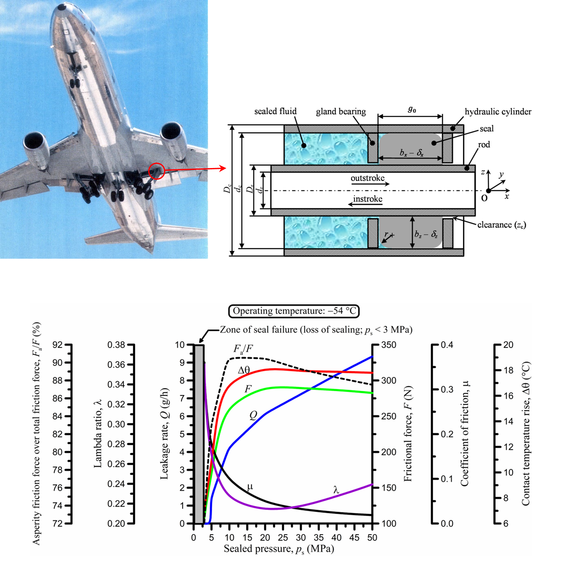
Rectangular-rounded, elastomeric, hydraulic seals (Figure 1) for reciprocating motion are used in a variety of applications such as in the automotive, aerospace, and marine industries. They constitute the simplest design of reciprocating seals together with the typical toroidal seal (O-ring). The materials they are made of (elastomers) obey nonlinear stress–strain laws of hyperelasticity or thermoviscoelasticity [1,2,3]. Their behavior strongly depends on temperature, strain, strain rate, and the history of loading, particularly at low temperatures, and especially, near or past the so-called glass transition temperature where elastomers exhibit a major stiffening. They are susceptible to ozone attack and oxidation causing aging and embrittlement, which is significantly accelerated at higher temperatures. They may also be chemically incompatible with various fluids, which not only cause elastomer degradation (such as solvents), but also swelling due to fluid uptake, exceeding 50% in severe cases [4]. The latter can increase the stress of installed seals in conjunction with changing their elastic modulus, thus altering their performance and leading to premature deterioration. Repeated loading may also cause depletion of seal plasticizers, effectively causing seal shrinkage that may reach 15% [4] and changes to the effective elastic modulus with consequences in the stress state of the seal during operation. The abovementioned issues restrict elastomeric reciprocating seals to operating in temperatures between −65 and +250 °C, sealed pressures of less than 80 MPa, and sliding velocities of less than 15 m/s, conditions which, of course, depend on the materials used. Nonetheless, these are very broad operating conditions. Moreover, elastomeric seals are deformable solids. Their performance in terms of leakage, friction, and abrasive wear is strongly linked to the pressure distribution in the inlet zone of the sealing contact [1,5,6], which essentially dictates the thickness of the fluid film in the contact. The inlet pressure distribution, in turn, depends on the local seal geometry. The latter is mainly set once a seal is installed in its housing or groove, but can also be dynamically varied by fluctuations in the sealed pressure, as well as during sliding motion, because of the inevitable friction in the sealing contact.
The picture painted thus far for the behavior of elastomeric hydraulic seals in reciprocating motion reveals a collage of different physical phenomena with complex interactions. It is characteristic that, even when great care is taken to study sealing performance under controlled conditions and in compliance with international standards and test protocols, some performance variations are unavoidable [7,8]. Consequently, numerical models developed to analyze such seals recently reached a high level of complexity, as in References [6,9,10,11,12,13,14,15,16,17,18,19,20], yet there is still space for improvement in terms of adding missing modeling details. Given the strong nonlinearity of the sealing problem, it is also very important to validate numerical codes against reliable experimental data, preferably covering a broad range of operating conditions including sealed pressures, stroking velocities, and temperatures.
Despite the volume of research on hydraulic, reciprocating, rubber-like seals published in the last 50 years or so, systematic, theoretical parametric studies are almost non-existent. There are three main reasons for this deficiency. Firstly, the topic is still under fundamental research, with ever more complex numerical models under development and verification, which takes time and effort. Secondly, most of the high-quality numerical models utilize commercial software of finite element analysis or even computational fluid dynamics, both of which require lengthy preparation and running times, making them unsuitable for extensive parametric analyses. Thirdly, there is lack of reliable experimental data for the plethora of existing seal designs, except for the most basic, that is, the rectangular-rounded and toroidal seals. Thus, even though sophisticated numerical models are being developed, validating them and executing the related computational codes tens or hundreds of times for a detailed parametric analysis is difficult and time-consuming.
In lack of systematic, theoretical parametric studies, there are a handful of reviews, as well as several studies, which present various results in terms of leakage and friction. A historical review of those studies since the dawn of scientific sealing research in the 1930s and up to the year 2008 was presented by Nikas [1,2] with extensive bibliography. Earlier reviews were also presented by Field and Nau [21] on experimental work up to the early 1970s, Nau [22,23] on research work up to the 1990s, Kanters [24] and Visscher and Kanters [25], also on experimental work up to the 1990s, and a few other brief reviews by Flitney [26] and Ramsdell [27] in the 1980s, and, more recently, by Bisztray-Balku [28,29] in 1999 and 2004. Interestingly, or rather, surprisingly, one of the most thorough studies to date remains the pioneering experimental and theoretical study conducted by White and Denny in the 1940s [30,31], despite the engineering limitations at that time in comparison to modern facilities.
The present study is based on a recently published numerical model of the author [6] and in-house developed software ROSEAL, which analyzes rectangular-rounded, elastomeric, hydraulic rod seals in reciprocating motion. The model is almost entirely analytical and mostly based on explicit algebraic equations to deal with the solid mechanics, contact mechanics of rough surfaces, and thermoelastohydrodynamics of a rod–seal tribopair. It incorporates a large number of design parameters and variables, and it is numerically optimized to compute sealing performance in terms of leakage, friction force, and a multitude of other parameters in infinitesimal time (on the order of 0.05 s) with a modern personal computer. The model was extensively validated against leakage and friction experimental results for a broad range of operating conditions [8], including a broad range of temperatures between −54 and +135 °C, conditions which are of vital importance in the aviation industry. In fact, the research work originated from the author’s collaboration with a major seal manufacturer to develop a computational tool for the analysis of polymeric reciprocating seals for linear hydraulic actuators used in aircraft landing gear (Figure 2) [32] and rotary vane actuators for the control of wing flaps [33,34]. The model is, thus, suitable for an extensive parametric analysis, which is lacking in the literature. Thus, it is employed here to present leakage, friction, and other performance results under the influence of seal geometry (seal width and corner radius), seal material (elastic modulus), operating conditions (sealed pressure and stroking velocity), design parameters (rod surface roughness and seal radial interference), and chemical compatibility of the seal material and the sealed fluid expressed by the amount of seal swelling in operation. Crucially, the effects of all aforementioned variables were analyzed and presented at three temperatures: −54, +23, and +135 °C. The input data are for real seals and hydraulic fluid used in linear hydraulic actuators for aircraft landing gear [6,8,32]. The results show that sealing performance is a complex, multivariable, nonlinear problem involving solid and contact mechanics, materials science, and lubrication, and it requires attention to detail to master. Nevertheless, inspecting these results on the simplest of seal geometries reveals sealing principles that can be adopted to geometries other than rectangular-rounded and toroidal.
2. Mathematical Model
The mathematical model at the core of this study was presented in every detail and experimentally validated at operating temperatures of −54, +23, and +135 °C in Reference [6]. The model consists of solid mechanics, contact mechanics of rough surfaces, thermoelastohydrodynamics, and performance analysis of rectangular-rounded, elastomeric, hydraulic rod seals for reciprocating motion. It is physically based, in that it relies on physical laws and classic equations of solid mechanics, contact mechanics, and fluid mechanics to reach its target, which is the evaluation of sealing performance in terms of leakage, friction, and possible seal extrusion. It is also deterministic, that is, the results are always the same for given input data. Given its length and complexity with more than 80 detailed equations [6], it is unsuitable to repeat here. Instead, a descriptive summary is provided below and more formally presented in the flowchart of the numerical algorithm in Figure 3.
The solid-mechanics part of the model deals with the static analysis of a rectangular-rounded seal, using the Hookean equations of thermoelasticity. Selective averaging in certain directions is applied to those classic linear equations to iron out stress variations from the rounded corners of the seal. All components of the system, namely the seal, housing (groove or hydraulic cylinder), and the piston rod, are allowed to change dimensions according to the operating temperature. Restrictions are imposed on the seal during a thermal expansion, in accordance with the dynamic physical dimensions of its housing. The elastomeric seal is allowed to swell due to fluid uptake or shrink due to plasticizer depletion in a proportion that is set at the beginning of the analysis. Thus, the dynamic stress and strain state of the seal is completely determined, taking into account all dimensional and thermophysical constraints of the system. This allows calculating the pressure distribution in the sealing contact, which is subsequently used to solve the elastohydrodynamic lubrication problem.
The lubrication problem of the ideally smooth sealing contact in reciprocating motion is solved on the basis of the one-dimensional Reynolds equation for steady-state conditions with allowance for pressure- and temperature-dependent mass density and dynamic viscosity of the sealed fluid. This approach is suitable when the stroke length is at least twice the sealing contact width, allowing a film to be theoretically developed along the whole width of the contact. The Reynolds equation is modified and numerically solved for the pre-calculated contact pressure as an ordinary, first-order differential equation for the unknown film thickness. To accomplish this, it is necessary to know the value of the film thickness at one point in the ideally smooth contact to use in the boundary condition for the differential equation. The procedure to establish the boundary condition is detailed by Nikas [6], and requires a spatial approximation of the contact pressure at the rounded edges of the seal by a cubic polynomial. In this devised process, it is straightforward to set the level of fluid starvation by declaring the length of the inlet zone of the elastohydrodynamic contact in one of the equations of the model [6]. Thus, accounting for fluid starvation during, for example, an instroke (piston rod retraction), is a simple task. Moreover, in the solution process, heat generated by friction in the sealing contact is calculated and iteratively used in altering the fluid mass density and dynamic viscosity, with consequential effect on the computed film thickness, and, of course, on sealing performance.
Given that the sealing contact is between two rough surfaces, namely the surface of the rod and the (usually) much rougher surface of the seal, the contact-mechanics analysis is based on the statistical contact model by Greenwood and Tripp [35]. The elastohydrodynamic problem earlier described is solved for perfectly smooth surfaces to establish the average film thickness in the contact. The latter is then used as input to the statistical contact-mechanics model to calculate the expected number of contacts among counteracting roughness asperities. Correspondingly, the level of asperity interaction is computed in the form of average asperity pressures and the total area of asperity contact. Asperity interactions are assumed to take place in a boundary lubrication regime. Thus, the shear stress at the interface of engaged asperities is restricted by the pressure-dependent, limiting shear stress of the sealed fluid, as well as by the temperature-dependent shear strength of the softer material, which, in this case, is the elastomeric seal [6]. Furthermore, for two asperities in close proximity or nominal contact, a van der Waals stress is incorporated with the author’s model, which additionally, accounts for retardation or dispersion effects for asperity separations up to about 100 nm. Naturally, the properties of the nanometric film separating engaged asperities are also accounted for in calculating the van der Waals stress, which is accomplished by computing an equivalent Hamaker constant [6]. The van der Waals stress, which may be tensile or compressive depending on the nonretarded Hamaker constants of the rod, seal, and sealed fluid, is then superimposed on the average asperity pressure to compute the total asperity load.
Subsequently, the asperity load and the load solely supported hydrodynamically in the rest of the contact must balance the total contact load obtained by the solid-mechanics analysis. A numerical algorithm is then devised to ascertain that both the average film thickness and the temperature rise in the sealing contact converge within predetermined narrow limits as indicated in the flowchart of Figure 3. After that step, sealing performance is easily evaluated in terms of mass leakage rate of the sealed fluid, total friction force, and potential extrusion of the seal in the (normally narrow) clearance between the rod and the gland bearing in absence of a back-up ring. The total friction force comprises three terms as follows [6]:
- (a)
- the hydrodynamic friction force, which relates to the viscous friction of sealed fluid in areas of the sealing contact other than asperity micro-contacts;
- (b)
- the asperity friction force, which is calculated by the statistical contact mechanics sub-model and in effect of van der Waals stresses, with various nanofilm and material strength constraints as previously explained;
- (c)
- the deformation force, which emanates from the ploughing of rod roughness asperities through the softer asperities of the seal. This component is calculated by the author [6] on the basis of Gohar and Rahnejat’s analysis [36], but proved infinitesimal in all cases in Reference [6] and in the present study.
3. Parametric Study
The mathematical model and computer algorithm (Figure 3) detailed in Reference [6] was used to produce results on the effect of various critical parameters of the sealing system. The input data for the computations are given in Table 1, where the notation used by Nikas [6] is maintained for direct correspondence. Table 1 provides the reference values used in the computer program, some of which are varied as detailed later in the figures. The analysis is related to the experimental work of Nikas et al. [8], concerning rectangular-rounded, elastomeric seals for reciprocating motion in a linear hydraulic actuator. All data concern real working conditions and design parameters related to seals for aerospace applications (aircraft landing gear—Figure 2) as provided by a major seal manufacturer working in collaboration with aircraft manufacturers [6,8,32].
The following eight parameters were studied: the sealed pressure, the stroking velocity, the corner radius of the seal, the width of the seal, the radial interference of the seal, the root-mean-square (RMS) surface roughness of the rod, the elastic modulus of the seal, and the percentage of seal swelling by fluid uptake. Three graphs were prepared for each parameter, corresponding to three operating temperatures: +23, +135, and −54 °C. The extreme operating temperatures of +135 and −54 °C are crucial in aviation applications because they relate to the maximum operating temperatures encountered in hot climates on the ground and close to running aircraft engines (+135 °C), and minimum temperatures during flight (−54 °C) [32]. In fact, these are the exact operational limits of the hydraulic fluid used in those applications, which is specified as MIL-H-5606.
All results were averaged for one stroking cycle, consisting of one outstroke (rod extension), followed by one instroke (rod retraction). Sealing performance was evaluated in reference to six variables, which are defined below.
- Mass leakage rate (Q): the rate at which sealed fluid leaks to the air side of the system in one stroking cycle.
- Frictional force (F): the average, total frictional force in one stroking cycle, comprising hydrodynamic, asperity (including van der Waals interactions), and deformation (ploughing) components. It is important to reiterate at this point that, according to the results, the ploughing component of friction is infinitesimal. The van der Waals contribution also turned out to be negligible. Nevertheless, all the aforementioned friction-force components were included in the computations.
- Coefficient of friction (μ): the ratio of the total frictional force to the contact load.
- Contact temperature rise (Δθ): the average temperature rise from frictional heating in the contact.
- Lambda ratio (λ): the ratio of the average film thickness of the ideally smooth contact to the composite RMS roughness of the rod–seal tribopair. Given that the surface roughness is constant in this computation, the lambda ratio is proportional to the average film thickness in the contact.
- Ratio of asperity friction force to total friction force (Fa/F).
The variation in parameters was generally done in unequal steps, with more steps in regions of greater variation to capture important details. It is now timely to proceed with the results.
3.1. Sealed Pressure
Sealed pressure (ps) was varied between 0.1 and 50 MPa, as shown in Figure 4. Some elastomeric reciprocating seals can operate at sealed pressures up to 80 MPa [1,4], but applications where the pressure exceeds 35 MPa are rare. Given that typical elastomeric seals are nearly incompressible (Poisson’s ratio is very close to 0.5—Table 1), the sealed pressure is readily transferred to the contact zone and is added to the normal stress from the various interferences of the seal.
At 23 °C (Figure 4a), both the leakage rate and the frictional force are diminished when the sealed pressure tends to zero. For diminishing sealed pressure, lubrication conditions at the elastohydrodynamic inlet zone during the outstroke approach those of the elastohydrodynamic inlet zone during the instroke, which explains the lowering leakage per cycle. By increasing the sealed pressure, leakage per cycle is exponentially increased for ps < 10 MPa, and almost linearly increased for ps > 10 MPa. The frictional force (Figure 4a) is minimized at low sealed pressure, yet there is residual friction even at zero sealed pressure because the seal is installed with radial interference, meaning that it is pre-loaded. Following the increase in sealed (and thus, contact) pressure, the frictional force smoothly increases and maximizes before starting to drop at ps ≈ 25 MPa. This behavior is associated with the change in corner geometry as a result of seal compression by the increasing sealed pressure and the increase in lambda ratio for ps > 10 MPa. Figure 4a also reveals that the Fa/F ratio drops monotonically from its maximum value of about 91% at the lowest sealed pressure of 0.1 MPa to about 84% at the maximum sealed pressure of 50 MPa. Both the lambda ratio values of less than about 0.04 and the Fa/F ratio with values exceeding 84% in the whole range of ps prove that the seal operates in a boundary lubrication regime. The coefficient of friction exhibits a diminishing trend as it is strongly influenced by the asperity component of the friction force [6] and drops monotonically from about 0.102 at ps = 0.1 MPa to about 0.007 at ps = 50 MPa, values which are typical of boundary and elastohydrodynamic lubrication, respectively, according to the Stribeck curve [37]. However, as stated earlier, the lambda and Fa/F ratios clearly show that the seal operates in the boundary lubrication regime (λ < 1) in the whole interval of sealed pressure. The hint of elastohydrodynamic lubrication implied by the low value of the coefficient of friction for high sealed pressure is, in fact, misleading in this case, and the Stribeck curve should only be interpreted in its proper context, that is, in reference to the lambda ratio. Finally, the contact temperature rise (Δθ) exhibits a smooth drop with increasing sealed pressure, given that it is strongly influenced by the asperity friction force; yet, it remains without significant change in magnitude close to about 5 °C.
The trend of the results at 135 °C is similar (Figure 4b). Naturally, at such a high temperature, the dynamic viscosity of the sealed fluid is extremely low (about 0.004 Pa·s), resulting in a very thin lubricating film as indicated by the magnitude of the lambda ratio. Accordingly, leakage per cycle is significantly reduced. However, the frictional force is significantly lower than that at 23 °C. This is mainly caused by the lower viscosity of the sealed fluid at 135 °C, resulting in lower hydrodynamic friction. The latter is also reflected upon the lower coefficient of friction.
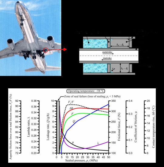
At the other end of the temperature scale, that is, at −54 °C (Figure 4c), there are some remarkable changes. Firstly, owing to the significant thermal contraction of the seal, contact pressure is lost if the sealed pressure drops below 3 MPa. To avoid sealing failure for ps < 3 MPa, it is necessary to increase at least one of the interferences of the seal (δx, δy, and δz in Table 1). Secondly, the lambda ratio is significantly greater as a result of the substantially increased dynamic viscosity of the sealed fluid, which facilitates the development of a full lubricating film in the contact. The increased viscosity also causes much higher viscous losses due to increased hydrodynamic friction. Moreover, there is major stiffening of the seal as it operates close to its glass transition temperature, causing a major rise in asperity contact pressures, and thus, asperity friction. These changes are reflected upon the dramatically increased friction force, which reaches a maximum value of 289 N, whilst it does not exceed 111 N at 23 °C and 72 N at 135 °C. Accordingly, the friction coefficient also substantially increases, particularly at low sealed pressure. There is also a much higher temperature rise of up to 18 °C, which almost ceases for ps > 15 MPa following the trend of the lambda ratio curve. Such a high temperature rise has a significant effect on the dynamic viscosity of the sealed fluid and the inlet conditions of the sealing contact, which dictate the average film thickness according to the inverse hydrodynamic theory [6].
In summary, to minimize both the mass leakage rate and the frictional force, it is necessary to keep the sealed pressure as low as possible to maintain sealing even at the minimum expected operating temperature. Naturally, a safety margin should also be allowed to account for seal abrasive wear (loss of surface material) and potential seal shrinkage from depletion of any elastomer plasticizers, as explained later.
3.2. Stroking Velocity
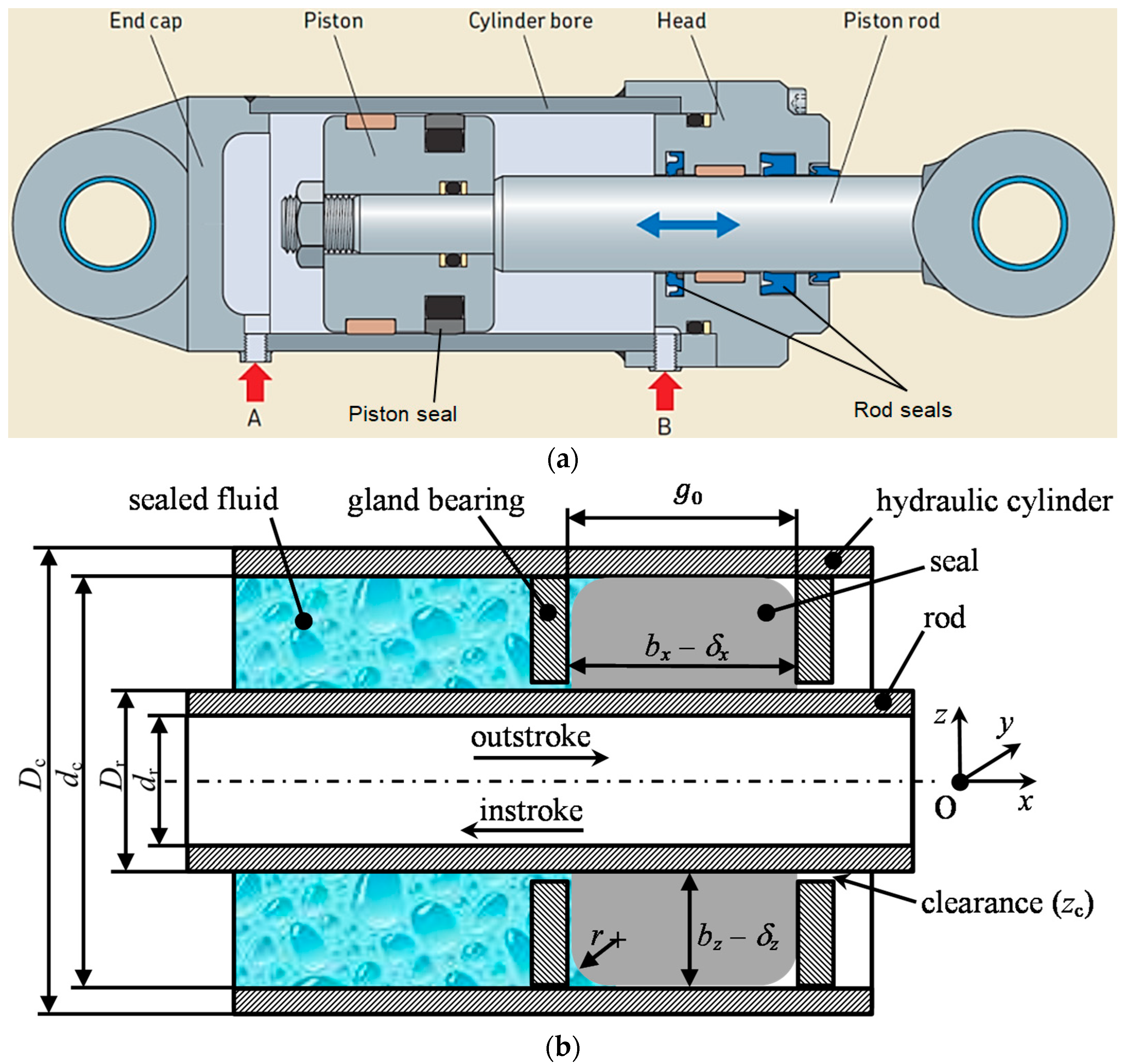
Stroking velocity (V) was varied between 0.01 and 15 m/s, as shown in Figure 5. The upper limit of 15 m/s is normally the maximum met in polymeric reciprocating seals [1,4], because, at such a high sliding speed, wear and frictional heating are intolerable to most polymers.
At 23 °C (Figure 5a), the leakage rate shows an exponential rise with the velocity, following the rapid increase in lambda ratio, and thus, the average film thickness. The frictional force, essentially being the sum of hydrodynamic and asperity friction components, has two trends: it rises for increasing velocity up to 3 m/s as a result of increasing viscous losses, and it drops if the velocity is further increased, as a result of film thickening and a corresponding reduction in asperity friction; the latter is clearly seen in the variation in Fa/F ratio. The exact same behavior is exhibited by the coefficient of friction. The temperature rise in the contact is substantial for higher velocities, and exceeds 60 °C at V = 15 m/s, which is an admittedly very high velocity for elastomeric seals. Inevitably, such a high temperature rise affects fluid mass density and dynamic viscosity in the inlet zone, directly influencing the average film thickness in the contact. Thus, there are interactions at play which are difficult to predict quantitatively without the full numerical solution, as in this case [6].
At 135 °C (Figure 5b), the trend of some results changes. The leakage rate exhibits the same exponential rise with velocity, though, in absolute terms, leakage is significantly reduced following the reduced lambda ratio. What is evidently different at 135 °C in comparison with the results at 23 °C is the trend of the frictional force and the coefficient of friction, which both keep rising with increasing velocity, albeit at a reduced rate after the initial rapid ascent. The shear strength of the seal at 135 °C is lower than the limiting shear stress of the sealed fluid for the given sealed pressure, and it is the prevailing limiting stress factor in the contact. The thermally induced softness of the seal at 135 °C is coupled with a significant temperature rise in the contact, which reaches 42 °C at V = 15 m/s, resulting in a contact temperature of 135 + 42 = 177 °C, and creating interfacial conditions favorable for severe wear, including a high risk of thermal and vaporization damage to the seal [4]. Figure 5b clearly shows that it is crucial to keep the sliding velocity as low as possible for minimizing leakage, friction, and wear.
At −54 °C (Figure 5c), the trend of the friction results changes again. Given the high dynamic viscosity of the sealed fluid at that temperature, viscous drag is strong. However, asperity pressures are very high and strongly influence friction at low lambda ratios (equivalent to thin fluid films) at low velocity. This effect rapidly decays for thickening film at higher velocity with the strong reduction in Fa/F ratio. Additionally, thermal effects are strong: the average temperature rise in the contact at V = 6 m/s reaches 40 °C during the outstroke and 120 °C during the instroke, giving a mean value of 80 °C for the stroking cycle. Obviously, frictional heating in this case dramatically alters the contact conditions by reducing fluid viscosity, including the elastohydrodynamic inlet zone, conditions which are far from what would have been envisioned had frictional heating been ignored and the false impression of the extremely low operating temperature (−54 °C) been kept in mind. This is also reflected on the zero leakage per cycle shown in the figure. In fact, the particular leakage result comes from the relatively low sealed pressure of 3.4 MPa. For greater sealed pressures, e.g., 10 MPa, leakage rate is nonzero. Nevertheless, the great reduction in friction force and minimization for velocity greater than about 3 m/s for the given problem clearly point to an optimal velocity range, e.g., 2 to 3 m/s, taking into consideration the temperature rises from frictional heating as well. When the velocity exceeds 8 m/s, the average lambda ratio exceeds the critical value of 3, and asperity friction ceases as is indicated by the nullification of the Fa/F ratio. Without asperity friction, frictional heating is abruptly reduced, resulting in higher dynamic viscosity of the fluid and an abrupt increase in hydrodynamic friction. Operating with velocity greater than 8 m/s is obviously very costly in terms of frictional losses.
In summary, to minimize both the mass leakage rate and the frictional force, it is necessary to keep the stroking velocity as low as possible, except at low sub-zero temperatures where there may exist an optimal velocity range of appreciable magnitude, e.g., 2 to 3 m/s. However, maintaining a very low velocity comes at the expense of abrasive wear, because the seal operates with lower lambda ratio, and the latter is critically important at low, sub-zero temperatures where the seal is substantially more stiff and brittle.
3.3. Corner Radius of the Seal
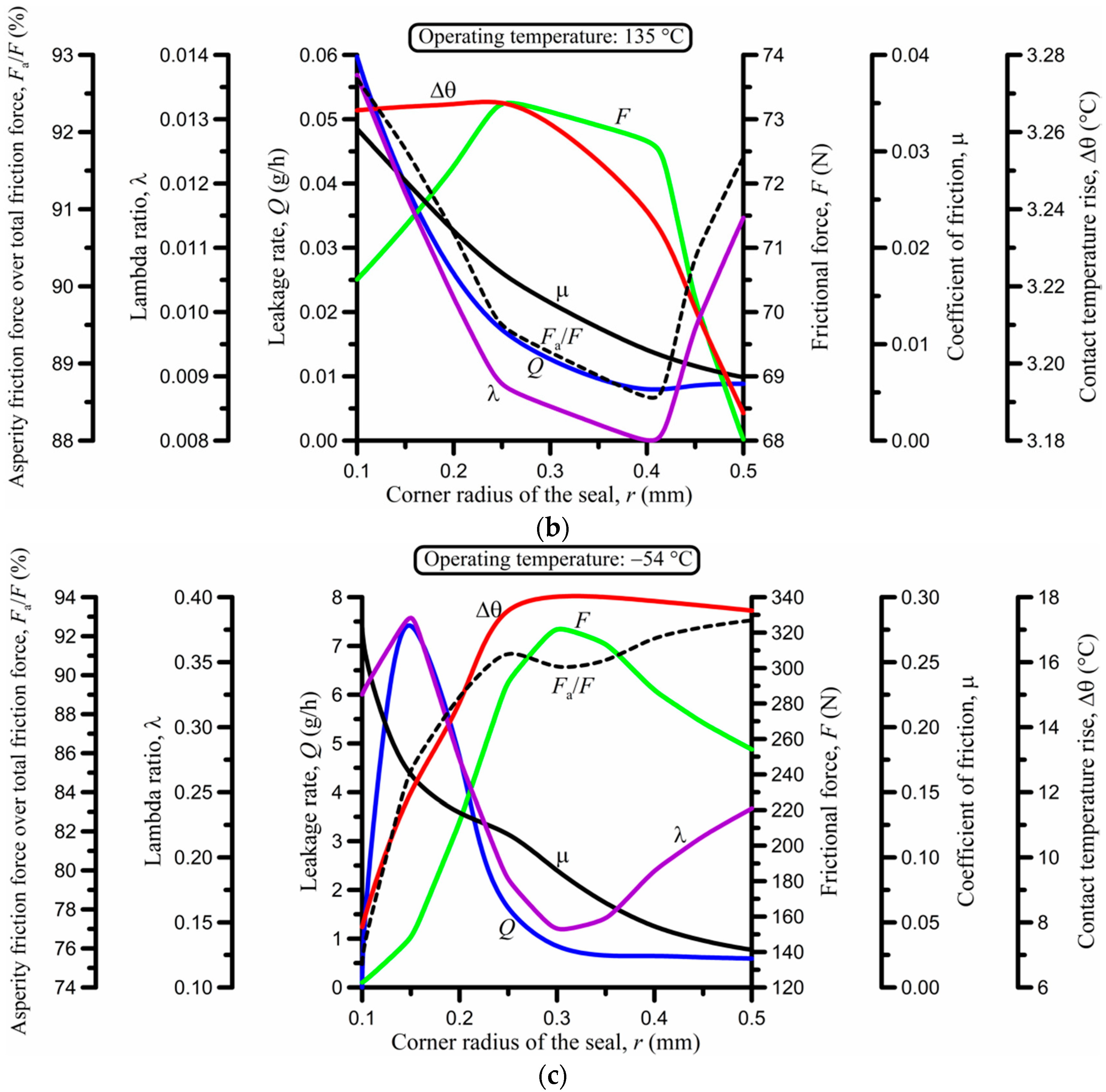
The corner radius r (or edge radius of curvature) of the seal was varied between 0.1 mm for sharp corners and 0.5 mm for more rounded corners, as shown in Figure 6. This is a typical range for rectangular-rounded dynamic seals [1,2,5,6,8,9,10,11,12,13,32]. Figure 6 reveals that the corner radius has a strong, nonlinear effect on all studied performance variables. More rounded seal corners facilitate the development of a hydrodynamic film in the contact, but also reduce the contact width, causing the opposite effect for a given contact load. Thermal effects are generally weak with an average rise in temperature of up to 5 °C, except at low, sub-zero operating temperature where Δθ can reach 18 °C (Figure 6c). Therefore, most of the effect of changing r comes from the changes in the lambda ratio and the size of the contact in conjunction with effectively changing the elastohydrodynamic-contact inlet-zone length, whose upper limit is equal to r [6].
According to Figure 6, the leakage rate is minimized and the frictional force is maximized in a critical interval of r, which depends on the operating temperature. However, there are intervals of r where both the leakage rate and the frictional force are close to their minimum values, in addition to having a relatively high lambda ratio to reduce wear. The optimal value of r at 23 °C and also at 135 °C is 0.5 mm (Figure 6a,b), that is, the maximum value of r used in the simulation. In contrast, at −54 °C, the optimal value of r is at the other end of the scale, that is, r = 0.1 mm.
3.4. Seal Width
The width of the seal was varied between 1.00 and 3.75 mm, as shown in Figure 7. A wider seal facilitates the development of a thicker fluid film in the contact, because it results in a lower contact-pressure peak as long as the increased width does not cause added stress. The effect on all performance variables in Figure 7 is, thus, clear. At both 23 and 135 °C, all performance variables increase with seal width up to the point where the dynamic width (including interferences and thermal displacements) is equal to the dynamic groove width (also including thermal displacements); the latter is equal to 3.76 mm at 23 °C (Table 1). Indeed, the critical value of the original seal width is approximately 3.1 mm as realized by the abrupt change in trend of the curves in Figure 7a,b. Increasing the seal width past 3.1 mm causes added stress from the arising seal’s axial overlap, which, given the incompressibility of the seal’s material, is transferred to a large extent to the sealing contact, increasing the contact pressure. The latter causes a sharp reduction in lambda ratio, and accordingly, in leakage rate, whilst the frictional force continues rising, albeit at a much lower rate. A stark increase in contact load with a weak increase in frictional force past the critical seal width is also responsible for the abrupt drop in the coefficient of friction in Figure 7a,b. The average temperature rise is weak in these cases and does not exceed 5 °C.
The results are a little more complicated at −54 °C (Figure 7c). There are two important differences in comparison with the results at higher temperatures. Firstly, at the critical width of the seal (about 3.2 mm), the frictional force rises abruptly and reaches high values for a small further increase in seal width. This is owed to the stiffness of the seal at −54 °C, for its elastic modulus is 47 times greater than at 23 °C and 62 times greater than at 135 °C (Table 1), meaning that any additional axial stress from its spatial confinement causes a high, additional contact pressure. For that reason, the average temperature rise in the contact also abruptly increases past the critical seal width, as does the Fa/F ratio. Secondly, the average leakage rate is initially reduced, in contrast to what happens at positive operating temperatures, and is eventually nullified before locally peaking around the critical seal width. The leakage trend follows the trend of the lambda ratio in Figure 7c.
Overall, at 23 and 135 °C, the leakage per cycle and the average friction force per cycle are minimized for a narrow seal; the optimal width in these cases is 1 mm, which is the smallest width used in the simulation (Figure 7a,b). However, in absence of back-up rings, a narrow seal is more susceptible to roll deformation with consequential sealing failure. At −54 °C, the trend changes, and the optimal seal width for leakage and friction minimization is close to 2 mm for the conditions studied, which coincides with a local maximum of the Fa/F ratio (Figure 7c). These results presuppose that the dynamic width of the seal does not exceed the width of the seal groove during operation so that there is no added stress.
3.5. Seal Radial Interference
Radial interference (δz) of the seal was varied between 0 and 500 μm, as shown in Figure 8. This is a typical range for elastomeric reciprocating seals [1,2,5,6,8,9,10,11,12,13,32,33], including rotary vane seals [13,33]. Naturally, increasing the radial interference increases the contact pressure and reduces the average film thickness, thus reducing the lambda ratio as shown in Figure 8. Subsequently, Δθ also increases with δz, but the analysis shows that this change is negligible, regardless of the operating temperature. As expected, the leakage per cycle decreases and the average frictional force per cycle increases with δz, very strongly, in fact, for low δz. The crucial issue observed here is that there are intervals (or zones) of δz where contact pressure is low or even lost, signifying high probability or even certainty of loss of sealing. Although sealing is theoretically maintained when operating with δz in a zone of uncertainty for steady-state conditions, when vibrations of the sealing system or unplanned pressure fluctuations are considered, it is understood that sealing operation may be temporarily compromised. This is particularly true when considering seal abrasive wear and loss of material in time. At 23 °C, such a zone of uncertainty exists for δz < 15 μm (Figure 8a). At 135 °C, a wider zone of uncertainty exists for δz < 30 μm (Figure 8b). At −54 °C, thermal contraction of the seal results in an even wider zone of uncertainty, 110 μm < δz < 300 μm, in addition to a zone of certain loss of sealing for δz < 110 μm. It is obviously of major importance to accurately predict the existence and extent of such critical zones and to avoid system failure by prescribing interferences with sufficient safety margin, albeit not too large so as to avoid unnecessarily high frictional losses.
Therefore, selecting an optimal radial interference is an act of compromise among leakage, friction, and abrasive wear. Depending on the operating temperature, an optimal r could range between 100 and 500 μm. A precise analysis, such as that in Reference [6] and Figure 8, can narrow down the recommended r-interval for optimized operation, depending on application priorities such as, for example, minimum frictional losses.
3.6. Rod RMS Roughness
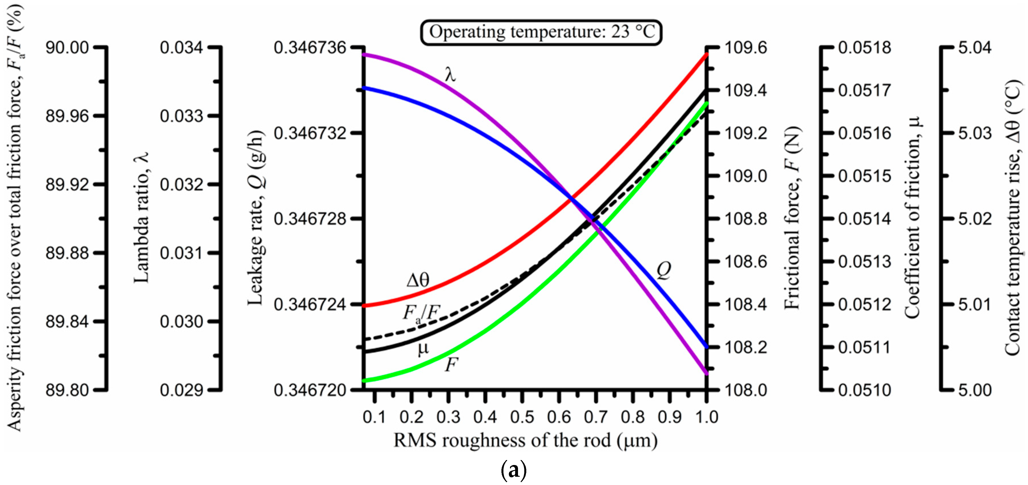
Assuming a Gaussian distribution of roughness asperities, the RMS roughness of the rod was varied between 0.07 and 1.00 μm, as shown in Figure 9. A value as low as 0.07 μm was achieved by polishing to produce a superfinished rod surface normally required in aerospace applications [8]. Generally, the RMS roughness of the rod was kept below 0.50 μm [8,32] to avoid excessive abrasive wear of the seal.
The number of decimal digits used for each variable and diagram in Figure 9 was chosen as necessary to make clear how strong or weak a variation was, which explains why there are a few decimal digits for some variables and many for others. Overall, Figure 9 reveals that the quantitative effect of the RMS roughness of the rod on all performance variables is very weak, particularly at 23 and 135 °C. The reason behind this result is that the RMS roughness of the seal is σs = 1.70 μm (Table 1), which is 1.7 to 24.3 times greater than the RMS roughness of the rod (σr) in the roughness scale of Figure 9. Thus, roughness effects in the form of the composite RMS roughness, , which is used in the contact-mechanics analysis [6], are dominated by the roughness of the seal. It should also be emphasized that, whilst the rod roughness is changed (and thus, the composite roughness is accordingly changed), product Π = saraσc (surface density of asperities × curvature radius of asperity tips × composite RMS roughness) in Table 1 is kept constant at 0.12. Thus, sara is varied at the rate of Π/σc = 0.12/σc with variable σc. It is shown in the experimental validation of the model by Nikas [6] that product Π has a strong influence on the friction-force results. However, the surface density of asperities (sa) and the curvature radius of asperity tips (ra) are very difficult to measure, and they also change during operation of the seal, although it can be argued that product Π could be taken as being constant in a first approximation [6,38,39,40].
As expected, the trend of some variables in Figure 9 is clear at all temperatures. Specifically, the lambda ratio decreases and the frictional force, coefficient of friction, and Fa/F ratio increase for increasing RMS roughness, which is logical to expect. The leakage rate and the temperature rise, on the other hand, are more complicated, yet only at first glance.
At 23 °C (Figure 9a), the leakage rate (per cycle) decreases smoothly with the roughness value. This result complies with the reduction in lambda ratio and greater proportion of the contact load being supported by roughness asperities (Fa/F ratio), as expected. At −54 °C (Figure 9c), this trend is maintained, and results in the nullification of the leakage per cycle. At 135 °C (Figure 9b), the lambda ratio is so small that nonlinearities of the system come to surface, which is reflected on the nonlinear variation of the leakage rate (Q). However, the exposed variation in Q in Figure 9b appears deceptive until it is realized that the range of Q is just 0.1 ng/h for the wide range of RMS roughness in the figure. A similar trend is seen for the average temperature rise in the contact: the variation is very weak at 23 and −54 °C, and totally negligible at 135 °C.
In summary, there is benefit in having a smooth rod surface to minimize leakage, friction, and wear, despite the benefit being quantifiably very small. This means that the performance benefit offered by superfinishing should be contemplated in the cost of the process. This conclusion was emphasized in earlier numerical and experimental studies of the author [8,32,33], together with the experimentally obtained fact that rod roughness must be considered in conjunction with the seal radial interference for optimal performance, and not independently [8]. Moreover, it should also be remembered that a rougher rod surface will accelerate seal abrasive wear. This could be in the form of wear particles, as well as in the form of a polymeric film deposited on the rod [41,42,43]. In either case, friction and leakage will be affected by particle overrolling, creation of leak channels, particle blockage of the elastohydrodynamic inlet zone, alteration of the effective surface roughness of the rod by deposited films, etc. Therefore, rod roughness should be kept low anyway, but without necessarily opting for a superfinished effect.
3.7. Seal Swelling
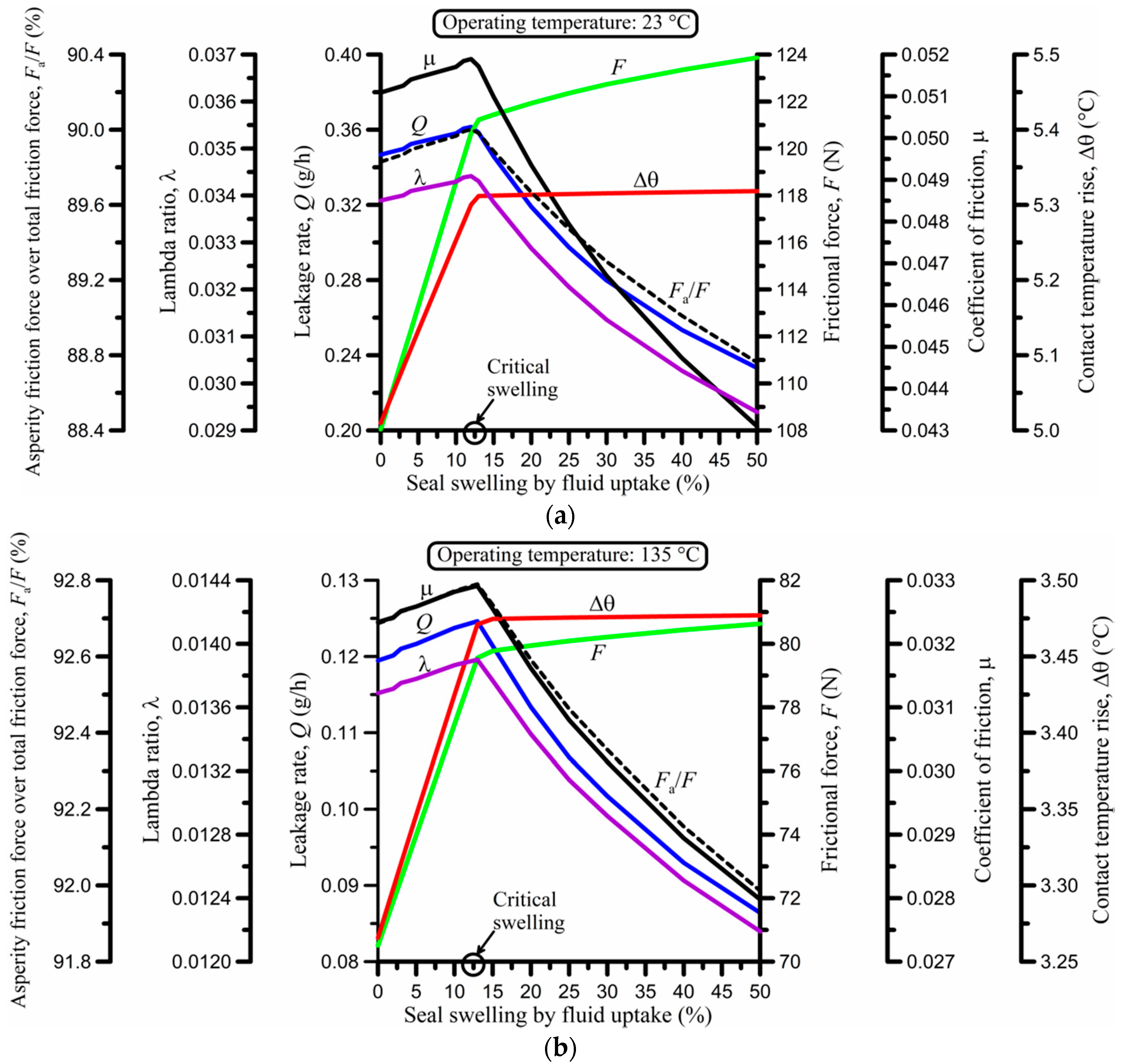
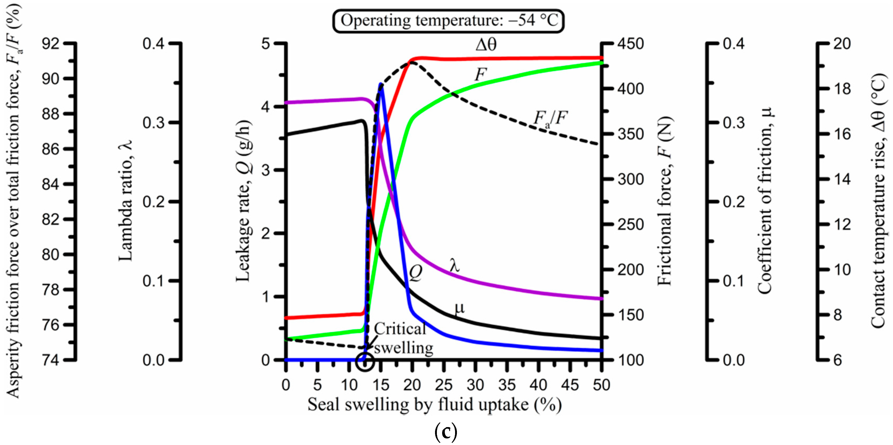
Fluid uptake by elastomeric seals typically results in seal swelling (volume increase) by up to 15%, unless there is chemical incompatibility between the seal and the offensive fluid, that is, similarity in their chemical structures. In this case, swelling of more than 30% can occur, particularly at higher temperature, e.g., at over 100 °C [4,44]. Seal swelling was, thus, realistically varied between 0 and 50%, as shown in Figure 10. As the seal swells, it tends to fill any available space. The result is similar to that observed when the width of the seal is increased. Therefore, it is expected to observe behavior similar to that seen earlier in Figure 7. Indeed, this is obvious upon comparing Figure 7 and Figure 10. Figure 10 shows that, at some critical swelling of about 13% for the data used in the analysis (Table 1), the seal is axially extended to the point where its width matches that of the groove during operation. Reaching the critical swelling fuels drastic changes in all performance variables. The explanations for those changes are similar to those given in Section 3.4 for the effect of the seal width. Seal swelling causes increased frictional force and related losses according to Figure 10, regardless of the operating temperature. It should be noted that the rise in frictional force at −54 °C in particular is abrupt because of the stiffness of the seal at such a low temperature: a 235% increase in force from 156 to 366 N takes place when swelling changes from 13% to 20%. Nevertheless, swelling can be beneficial in terms of leakage past the critical swelling point because of the added contact pressure, except for low, sub-zero temperature. Indeed, at −54 °C (Figure 10c), the leakage rate is zero below the critical swelling value and positive above the critical value. To justify this behavior, it must be recalled that, once the seal expands to the point where it starts to be axially compressed in its groove, its rounded edges are also compressed with the effect of changing the local geometry and the elastohydrodynamic inlet zone conditions that govern the formation of a fluid film; the reader is referred to the dynamic seal interferences, cx and cz, given by Equations (46) and (47) by Nikas [6].
Overall, and given the substantial increase in frictional loss and abrasive wear as indicated in Figure 10 (not to mention the risk of extrusion damage in absence of back-up rings), it is strongly recommended to avoid contact of chemically incompatible fluids with the seal in order to eliminate the risk of seal swelling. However, it should be noted that seal shrinkage from the depletion of plasticizers (if used) during repeated pressurization is also a possibility, with shrinkage values of up to 15% [4,44]. Therefore, it may be beneficial to have some minor swelling in some cases just to cancel shrinkage, though that is difficult to estimate and control. Both swelling and shrinkage change the effective elastic modulus or stiffness of the seal, causing additional issues that should be considered as in the model of Nikas [6] for a precise analysis of such effects. The effect of the elastic modulus of the seal is, in fact, examined next in Section 3.8.
3.8. Elastic Modulus of the Seal
The elastic modulus of the seal was varied between 1 and 200 MPa, as shown in Figure 11. This range covers typical elastomeric seals at temperatures between low sub-zero values where elastomeric seals are stiff to values in excess of 150 °C where seals are soft [1,2,3,4]. Thus, there is no need for a parametric study in terms of temperature in this case—temperature effects are effectively included in the wide range of elastic moduli used in Figure 11.
The effect of increasing the elastic modulus of the seal is plain to see in Figure 11. A small increase in the elastic modulus causes a significant increase in contact pressure, given that the seal is nearly incompressible. The added seal stiffness for increasing modulus has a strong influence on the deformed geometry of the rounded edges of the seal, with a corresponding effect on the elastohydrodynamic conditions in the inlet zone. Essentially, the average gradient of the pressure distribution at the edges of the seal is greater if the seal is stiffer. In this way, there is a sharp drop in the lambda ratio, the leakage per cycle, and the coefficient of friction, particularly for a modulus in the interval of 1 to 20 MPa. A nearly linear increase in frictional force is also clear for moduli up to 100 MPa, followed by another linear increase with a lower slope for moduli greater than 100 MPa. The average rise in contact temperature is modest with a maximum recorded value of about 9 °C, and does not change for moduli in excess of 100 MPa. Selecting optimal values in this case with the aid of Figure 11 is obviously a matter of compromising among leakage, friction, and wear. Nevertheless, it is clear that an elastic modulus of about 5 to 20 MPa gives low frictional force and low (though not zero) leakage rate. This is, in fact, a typical value range for elastomeric rod seals used in aircraft hydraulic actuators as in the present case [5,8,9,10,11,12,32], which gives reason to believe that this selection by the industry is purposeful and well established in practice.
4. Conclusions
The performance of hydraulic, elastomeric seals for reciprocating motion is affected by many parameters, some of them critical. Proper selection of these parameters is required not only for optimized performance, but often to avoid sealing failure. This theoretical study analyzed the effects of important parameters for rectangular-rounded seals operating at −54, +23, and +135 °C, covering a wide range of applications and even extreme conditions met in the aerospace industry. The results are based on a physically based, deterministic mathematical model of the author [6], which was validated against experimental data obtained at the three aforementioned temperatures by a major seal manufacturer [8]. There are interactions among many sealing parameters, which perplex the analysis; these were discussed in Section 3. A summary of the important conclusions pertaining to optimization is given below.
- (a)
- The sealed pressure (Figure 4) should be kept as low as possible to minimize both the leakage per cycle and the average frictional force per cycle, provided sealing is maintained even at the minimum expected operating temperature. Seal shrinkage caused by depletion of plasticizers (if any are used) and seal abrasive wear leading to loss of seal material should be considered in designing a safety margin and avoiding sealing failure when operating at low temperature and low sealed pressure.
- (b)
- The stroking velocity (Figure 5) should be kept as low as possible to minimize leakage per cycle and the average frictional force per cycle, except at low sub-zero temperatures where an optimal velocity range of appreciable magnitude (for example, 2 to 3 m/s) may exist. However, the reduction in stroking velocity should be contemplated in view of reduced film thickness, and thus, increased seal abrasive wear, which is critical at low sub-zero temperatures given the corresponding stiffness and brittleness of the seal.
- (c)
- The corner radius of the seal (Figure 6) has a strong effect on sealing performance. At positive temperatures, the optimal radius for the minimization of leakage and frictional force is at the high end of the radius scale (e.g., 0.5 mm for the data in the present analysis), whereas at low, sub-zero temperatures, the optimal radius is at the other end of the scale (0.1 mm for the data in the present analysis). Moreover, there is an intermediate interval, the position and extent of which depends on the operating temperature, where leakage is minimized and frictional force is maximized.
- (d)
- The width of the seal (Figure 7) is also strongly influential to sealing performance. At positive temperatures, the leakage per cycle and the average frictional force per cycle are minimized for a narrow seal. However, a narrow seal is more sensitive to extrusion damage and roll deformation that leads to sealing failure. At low, sub-zero temperatures, the optimal seal width for leakage and friction minimization is somewhere in the region of 2 mm for the conditions studied. These results are valid as long as the dynamic width of the seal does not exceed the width of the seal groove during operation so that there is no additional stress.
- (e)
- The radial interference of the seal (Figure 8) is usually in the range of 100 to 500 μm and strongly depends on the operating temperature. A globally optimal radial interference does not exist. Instead, a locally optimal interference based on some criteria is possible. The criteria must accept a compromise among leakage, friction, and wear. Particular attention should be paid to the critical minimum interference to avoid sealing failure from total loss of contact pressure at low operating temperatures (Figure 8c). To this effect, the reader is reminded of the tragic loss of the National Aeronautics and Space Administration (NASA) space shuttle Challenger in 1986 [1,45], which was forensically blamed on the freezing of a static O-ring the night before launch.
- (f)
- The RMS roughness of the rod (Figure 9) has a weak effect on sealing performance because interfacial phenomena at the sealing contact are dominated by the typically much rougher seal. Nevertheless, to avoid excessive seal wear, a relatively smooth rod is always recommended (RMS roughness of no more than 0.5 μm). However, going to extremes with superfinishing and having RMS values of less than 0.1 μm should be balanced against the cost of the process and the risk of being sometimes detrimental to friction and wear, with higher friction and frictional heating at higher stroking velocities because of boundary lubrication effects [4]. It can be hypothesized that sealed fluid stored in roughness valleys of the rod help avoid fluid starvation during instrokes.
- (g)
- Seal swelling due to fluid uptake (Figure 10) causes higher stress and can increase friction and leakage per cycle. At a critical level of swelling, which depends on the operating temperature and the particular dimensions of the sealing system, a swollen seal may fill all available space in its groove. Operation past that critical level results in very high stresses and a substantial increase in frictional force. Thus, seals must be chemically compatible with sealed fluids and avoid contact with chemically incompatible contaminants that could cause swelling. In some cases, a minor swelling (e.g., 5%) may be beneficial if seal shrinkage from depletion of plasticizers also takes place, such that swelling cancels shrinkage [4].
- (h)
- The elastic modulus of the seal (Figure 11) has a strong effect on leakage and friction. Increasing the elastic modulus causes a sharp decrease in leakage per cycle and substantial increase in frictional force. These effects are much more pronounced for elastic moduli in the region of 1 to 10 MPa. An optimal elastic modulus of about 5 to 20 MPa at room temperature is recommended to achieve leakage per cycle and average frictional force per cycle close to their minimum values.
5. Discussion
It should be emphasized that the performance of hydraulic polymeric seals is, in reality, often influenced by unforeseen factors. For example, seal deterioration due to improper storage conditions prior to seal installation, degradation due to radiation and atmospheric ozone prior to or during service, contamination of the sealed liquid by solids (e.g., sand) or liquids (e.g., solvents), and, in fact, a multitude of normal or abnormal wear modes as detailed by Nikas [4]. A deterministic model [6] and parametric analysis such as the present one can only go as far as the precision of the given input data, and it assumes invariable operating conditions to complete the evaluation. This means that the reliability of the quantified predictions, which was experimentally verified in Reference [6] for a given (broad) range of input data, is linked to the given input data and their intervals of variation as, for example, in Figure 4, Figure 5, Figure 6, Figure 7, Figure 8, Figure 9, Figure 10 and Figure 11. Interpolation of the parametric results within the given ranges, e.g., any stroking velocity between nearly zero and 15 m/s in Figure 5, is of course allowed, but extrapolation to values that significantly deviate from the limits used in the figures, e.g., stroking velocity of, say, 20 m/s, is, generally, not recommended and should not be applied without scrutiny. For the latter scenario, that is, operation outside the ranges shown in Figure 4, Figure 5, Figure 6, Figure 7, Figure 8, Figure 9, Figure 10 and Figure 11, only a numerical model such as that of Reference [6] could provide quantifiable predictions that could be relied upon.
6. Outlook for Future Research
A complete parametric and optimization study such as the present one is normally the last step in a lengthy process of computational modeling (of course always accompanied by the necessary experimental validation). The author has been involved in fundamental research on rectangular-rounded hydraulic reciprocating seals for nearly 20 years, and has numerically modeled almost all plausible performance aspects of this type of seal. That includes solid mechanics with linear and nonlinear (finite) thermoelasticity (e.g., [10]), rough-surface contact mechanics with frictional heating [6], transient thermoelastohydrodynamics (e.g., [9]), van der Waals intermolecular forces as pertaining to friction [6], fluid starvation and seal swelling or shrinkage during operation [6], and related specialized topics such as anti-extrusion rings [11], tandem seals [12], rotary vane seals for alternating motion [13], and composite seals [46]. Following the experimental research project [8] and subsequent numerical model [6] built upon and validated against it, the present parametric and optimization study is seemingly the final step, at least for single, simple (non-composite) rectangular-rounded, hydraulic elastomeric seals with no back-up rings. Nevertheless, future research could potentially expand to parametrically cover areas such as those listed below.
- Sealing performance in reference to fluid starvation.
- Seal abrasive wear. It is most likely that this will be based on empirical equations.
- Sealing performance at temperatures lower than the glass transition temperature, which is a very specialized, yet crucially important topic as space shuttle Challenger’s destruction dramatically proved [45].
- Seal life prediction. Again, this is a highly specialized topic and influenced by many variables such as shelf life prior to first use, changes to environmental conditions during a seal’s life, effects of atmospheric ozone, radiation, temperature, and humidity variations, and several others. Unfortunately, such is the broadness and uncertainty of operating conditions of most typical seals that making quantifiable, reliable predictions of their life expectancy is rather an academic exercise with little value in practice.
Funding
This research received no external funding.
Conflicts of Interest
The author declares no conflict of interest.
References
- Nikas, G.K. Eighty years of research on hydraulic reciprocating seals: Review of tribological studies and related topics since the 1930s. Proc. Inst. Mech. Eng. Part J J. Eng. Tribol. 2010, 224, 1–23. [Google Scholar] [CrossRef]
- Nikas, G.K. Research on the tribology of hydraulic reciprocating seals. In Tribology Research Trends; Hasegawa, T., Ed.; Nova Science Publishers: New York, NY, USA, 2008; pp. 11–56. ISBN 978-1-60456-912-4. [Google Scholar]
- Flitney, R. Seals and Sealing Handbook, 6th ed.; Butterworth-Heinemann: Oxford, UK, 2014; pp. 289–368. ISBN 978-0-08-099416-1. [Google Scholar]
- Nikas, G.K. Friction and wear of seals. In ASM Handbook Friction, Lubrication, and Wear Technology; Totten, G., Ed.; ASM International: Geauga County, OH, USA, 2017; Volume 18, pp. 957–968. ISBN 978-1-62708-141-2. [Google Scholar]
- Nikas, G.K.; Sayles, R.S. Study of leakage and friction of flexible seals for steady motion via a numerical approximation method. Tribol. Int. 2006, 39, 921–936. [Google Scholar] [CrossRef]
- Nikas, G.K. Fast performance-analysis of rectangular-rounded hydraulic reciprocating seals: Mathematical model and experimental validation at temperatures between –54 and +135 °C. Tribol. Int. 2018, 128, 34–51. [Google Scholar] [CrossRef]
- Flitney, R.K.; Nau, B.S. Performance variation in reciprocating rubber seals for fluid power applications. STLE Lubr. Eng. 1988, 44, 993–1000. [Google Scholar]
- Nikas, G.K.; Almond, R.V.; Burridge, G. Experimental study of leakage and friction of rectangular, elastomeric hydraulic seals for reciprocating motion from –54 to +135 °C and pressures from 3.4 to 34.5 MPa. Tribol. Trans. 2014, 57, 846–865. [Google Scholar] [CrossRef]
- Nikas, G.K. Transient elastohydrodynamic lubrication of rectangular elastomeric seals for linear hydraulic actuators. Proc. Inst. Mech. Eng. Part J J. Eng. Tribol. 2003, 217, 461–473. [Google Scholar] [CrossRef]
- Nikas, G.K.; Sayles, R.S. Nonlinear elasticity of rectangular elastomeric seals and its effect on elastohydrodynamic numerical analysis. Tribol. Int. 2004, 37, 651–660. [Google Scholar] [CrossRef]
- Nikas, G.K. Theoretical study of solid back-up rings for elastomeric seals in hydraulic actuators. Tribol. Int. 2004, 37, 689–699. [Google Scholar] [CrossRef]
- Nikas, G.K.; Sayles, R.S. Computational model of tandem rectangular elastomeric seals for reciprocating motion. Tribol. Int. 2006, 39, 622–634. [Google Scholar] [CrossRef]
- Nikas, G.K.; Burridge, G.; Sayles, R.S. Modelling and optimization of rotary vane seals. Proc. Inst. Mech. Eng. Part J J. Eng. Tribol. 2007, 221, 699–715. [Google Scholar] [CrossRef]
- Öngün, Y.; André, M.; Bartel, D.; Deters, L. An axisymmetric hydrodynamic interface element for finite-element computations of mixed lubrication in rubber seals. Proc. Inst. Mech. Eng. Part J J. Eng. Tribol. 2008, 222, 471–481. [Google Scholar] [CrossRef]
- Stupkiewicz, S.; Marciniszyn, A. Elastohydrodynamic lubrication and finite configuration changes in reciprocating seals. Tribol. Int. 2009, 42, 615–627. [Google Scholar] [CrossRef]
- Thatte, A.; Salant, R.F. Visco-elastohydrodynamic model of a hydraulic rod seal during transient operation. ASME J. Tribol. 2010, 132, 041501. [Google Scholar] [CrossRef]
- Thatte, A. Multi-Scale Multi-Physics Model and Hybrid Computational Framework for Predicting Dynamics of Hydraulic Rod Seals. Ph.D. Thesis, Georgia Institute of Technology, School of Mechanical Engineering, Atlanta, GA, USA, 2010. [Google Scholar]
- S31t, T.; André, M.; Poll, G. A transient 2D-finite-element approach for the simulation of mixed lubrication effects of reciprocating hydraulic seals. Tribol. Int. 2010, 43, 1774–1785. [Google Scholar] [CrossRef]
- Thatte, A.; Salant, R.F. Effects of multi-scale viscoelasticity of polymers on high-pressure, high frequency sealing dynamics. Tribol. Int. 2012, 52, 75–86. [Google Scholar] [CrossRef]
- Liao, C.; Huang, W.; Wang, Y.; Suo, S.; Liu, Y. Fluid-solid interaction model for hydraulic reciprocating O-ring seals. Chin. J. Mech. Eng. 2013, 26, 85–94. [Google Scholar] [CrossRef]
- Field, G.J.; Nau, B.S. Film thickness and friction measurements during reciprocation of a rectangular section rubber seal ring. In Proceedings of the 6th International Conference on Fluid Sealing, Munich, Germany, 27 February–2 March 1973; pp. 45–56. [Google Scholar]
- Nau, B.S. The state of the art of rubber-seal technology. Rubber Chem. Technol. 1987, 60, 381–416. [Google Scholar] [CrossRef]
- Nau, B.S. An historical review of studies of polymeric seals in reciprocating hydraulic systems. Proc. Inst. Mech. Eng. Part J J. Eng. Tribol. 1999, 213, 215–226. [Google Scholar] [CrossRef]
- Kanters, A.F.C. On the Calculation of Leakage and Friction of Reciprocating Elastomeric Seals. Ph.D. Thesis, Eindhoven University of Technology, Eindhoven, The Netherlands, 1990. [Google Scholar]
- Visscher, M.; Kanters, A.F.C. Literature review and discussion on measurements of leakage, lubricant film thickness and friction of reciprocating elastomeric seals. STLE Lubr. Eng. 1990, 46, 785–791. [Google Scholar]
- Flitney, R.K. Reciprocating seals. Tribol. Int. 1982, 15, 219–226. [Google Scholar] [CrossRef]
- Ramsdell, R.G. A primer on fluid power sealing. Fundamentals of reciprocating seals. Hydraul. Pneum. 1986, 39, 63–65. [Google Scholar]
- Bisztray-Balku, S. Tribology of elastomeric and composite and reciprocating hydraulic seals. Periodica Polytech. Ser. Mech. Eng. 1999, 43, 63–80. [Google Scholar]
- Bisztray-Balku, S. Design development and tribology of reciprocating hydraulic seals. Periodica Polytech. Ser. Mech. Eng. 2004, 47, 163–178. [Google Scholar]
- White, C.M.; Denny, D.F. The Sealing Mechanism of Flexible Packings; MAP Scientific and Technical Memorandum No. 4/45 (Interim Report); H.M. Stationery Office: London, UK, 1945. [Google Scholar]
- White, C.M.; Denny, D.F. The Sealing Mechanism of Flexible Packings; Scientific and Technical Memorandum No. 3/47; UK Ministry of Supply; H.M. Stationery Office: London, UK, 1947. [Google Scholar]
- Nikas, G.K. Determination of Polymeric Sealing Principles for End User High Reliability. Technical Report DOW-08/01. Department of Mechanical Engineering, Tribology Group, Imperial College London: London, UK, 2001. Available online: www.tribology.me.uk/project5.htm (accessed on 31 August 2018).
- Nikas, G.K. Research of Fundamental Sealing Mechanisms Needed for Zero-Leakage High-Reliability Rotary Vane Actuators. Technical Report SMI-10/04. Department of Mechanical Engineering, Tribology Group, Imperial College London: London, UK, 2004. Available online: www.tribology.me.uk/project7.htm (accessed on 31 August 2018).
- Flitney, R.A. New seals improve the performance of rotary vane actuators. Seal. Technol. 2005, 2005, 3. [Google Scholar] [CrossRef]
- Greenwood, J.A.; Tripp, J.H. The contact of two nominally flat rough surfaces. Proc. IMechE 1970, 185, 625–633. [Google Scholar] [CrossRef]
- Gohar, R.; Rahnejat, H. Fundamentals of Tribology, 2nd ed.; Imperial College Press: London, UK, 2012; ISBN 978-1-84816-860-2. [Google Scholar]
- Hamrock, B.J.; Schmid, S.R.; Jacobson, B.O. Fundamentals of Fluid Film Lubrication, 2nd ed.; Marcel Dekker, Inc.: New York, NY, USA, 2004; ISBN 0-8247-5371-2. [Google Scholar]
- Greenwood, J.A.; Williamson, J.B.P. Contact of nominally flat rough surfaces. Proc. R. Soc. Lond. A 1966, 295, 300–319. [Google Scholar] [CrossRef]
- Fuller, K.N.G.; Tabor, D. The effect of surface roughness on the adhesion of elastic solids. Proc. R. Soc. A 1975, 345, 327–342. [Google Scholar] [CrossRef]
- Grimble, D.; Theodossiades, S.; Rahnejat, H.; Wilby, M. Tribology of rough ultra-film contacts in drug delivery devices. Proc. Inst. Mech. Eng. Part J J. Eng. Tribol. 2008, 222, 2209–2216. [Google Scholar] [CrossRef] [Green Version]
- Kim, A.T.; Seok, J.; Tichy, J.A.; Cale, T.S. Soft elastohydrodynamic lubrication with roughness. ASME J. Tribol. 2003, 125, 448–451. [Google Scholar] [CrossRef]
- Eiss, N.S., Jr.; Wood, K.C.; Herold, J.A.; Smyth, K.A. Model for the transfer of polymer to rough, hard surfaces. ASME J. Lubr. Technol. 1979, 101, 212–219. [Google Scholar] [CrossRef]
- Eiss, N.S., Jr.; Smyth, K.A. The wear of polymers sliding on polymeric films deposited on rough surfaces. ASME J. Lubr. Technol. 1981, 103, 266–273. [Google Scholar] [CrossRef]
- NewDealSeals. O-Ring Technical Handbook; NewDealSeals BV: Warmenhuizen, The Netherlands, 2015; Available online: www.newdealseals.com (accessed on 12 July 2018).
- Flitney, R.K. Redesigning the space shuttle’s solid rocket motor seals. Seal. Technol. 1996, 1996, 10–12. [Google Scholar] [CrossRef]
- Nikas, G.K.; Sayles, R.S. Modelling and optimisation of composite rectangular reciprocating seals. Proc. Inst. Mech. Eng. Part J J. Eng. Tribol. 2006, 220, 395–412. [Google Scholar] [CrossRef]
Figure 1.
(a) Linear hydraulic actuator with piston and rod seals (reproduced from the SKF Hydraulic Seals catalog SE/P1 12393/2 EN); (b) simplified model (not to scale) of the rectangular-rounded seal, and notation used to produce the results of this study in accordance with Reference [6] (with permission from Elsevier, 2018) (Note: all eight corners of the seal have the same curvature radius r).

Figure 2.
Aircraft landing gear with incorporated linear hydraulic actuator containing elastomeric rod seals: (a) gear being deployed; (b) gear being hydraulically retracted during takeoff.
Figure 2.
Aircraft landing gear with incorporated linear hydraulic actuator containing elastomeric rod seals: (a) gear being deployed; (b) gear being hydraulically retracted during takeoff.

Figure 3.
Flowchart of the numerical algorithm [6] (with permission from Elsevier, 2018).
Figure 3.
Flowchart of the numerical algorithm [6] (with permission from Elsevier, 2018).

Figure 4.
Effect of the sealed pressure at (a) 23 °C; (b) 135 °C; and (c) −54 °C.

Figure 5.
Effect of the stroking velocity at (a) 23 °C; (b) 135 °C; and (c) −54 °C.

Figure 6.
Effect of the corner radius of the seal at (a) 23 °C; (b) 135 °C; and (c) −54 °C.


Figure 7.
Effect of the seal width at (a) 23 °C, (b) 135 °C, and (c) −54 °C.


Figure 8.
Effect of the radial interference of the seal at (a) 23 °C; (b) 135 °C; and (c) −54 °C.

Figure 9.
Effect of the root-mean-square (RMS) roughness of the rod at (a) 23 °C; (b) 135 °C; and (c) −54 °C.
Figure 9.
Effect of the root-mean-square (RMS) roughness of the rod at (a) 23 °C; (b) 135 °C; and (c) −54 °C.


Figure 10.
Effect of seal swelling at (a) 23 °C, (b) 135 °C, and (c) −54 °C.


Figure 11.
Effect of the elastic modulus of the seal at 23 °C.


Table 1.
Input data for the numerical model of Nikas [6] in accordance with the experimental study of Nikas et al. [8]. The notation used by Nikas [6] is maintained.
| Input Data for the Numerical Model | Reference Values 1 |
|---|---|
| Average radius of curvature of asperity tips: ra (μm) | 1.5 |
| Boundary film thickness at asperity junctions: Da (nm) | 2 |
| Seal dimensions: bx (width); by (centerline circumference); bz (radial thickness) (mm) | 2.78; 107.63; 2.56 |
| Elastic modulus: Ec (cylinder); Er (rod) (GPa) | 118; 200 |
| Outer diameters of the rod and cylinder: Dr (rod); Dc (cylinder) | 31.7; 41.8 |
| Dynamic viscosity of the sealed fluid at atmospheric pressure: η0 (Pa·s) | where a = 23.73321954, b = 0.8002564166, and c = 0.00710539632; θ in °C 2 |
| Edge radius of curvature of the seal: r (mm) | 0.1 |
| Elastic modulus of the seal: Es at −54; 23; 135 °C (MPa) | 327.3; 6.9; 5.3 |
| Glass transition temperature of the seal (°C) | −56 to −60 |
| Initial groove width: (mm) | 3.76 |
| Interferences of the seal during installation: δx; δy; δz (μm) | 0; 0; 533 |
| Sealed-fluid limiting shear stress at atmospheric pressure: τ0 (MPa) | 4 |
| Mass density of the rod (kg/m3) | 7860 |
| Mass density of the sealed fluid at atmospheric pressure: ρ0 (kg/m3) | 858.5714286 − 0.7116402116θ (°C) 2 |
| Nonretarded Hamaker constants: cr (rod); cs (seal); cf (fluid) (J) | 4.0 × 10⁻¹⁹; 8.6 × 10⁻²⁰; 5.0 × 10⁻²⁰ |
| Operating temperature: θ (°C) | −54, 23, 135 |
| Percentage of seal swelling: S (%) | 0 |
| Poisson’s ratio: υc (cylinder); υr (rod); υs (seal) | 0.33; 0.30; 0.499 |
| Product Π = saraσc (surface density of asperities × curvature radius of asperity tips × composite root-mean-square (RMS) roughness) | 0.12 |
| Proportion of kinetic energy consumed in asperity deformation: β | 0.8 |
| Radial clearance of rod and gland bearing: zc (μm) | 20 |
| RMS roughness: σr (rod); σs (seal) (μm) | 0.07; 1.70 |
| Roughness maximum peak-to-valley height for the rod (μm) | 0.2 |
| Roughness maximum peak-to-valley height for the seal (μm) | 6 |
| Sealed pressure: ps (MPa) | 3.4 |
| Shear strength of the seal: (Pa) | = −0.009072938251, = 16.0829302 |
| Stroke length (mm) | 102 |
| Stroking velocity: V (mm/s) | 102 |
| Temperature of seal installation: θ0 (°C) | 23 |
| Thermal conductivity of the rod at temperature θ0: kr (W/(m·K)) | 42.3 |
| Thermal conductivity of the seal at temperature θ0 (W/(m·K)) | 0.24 |
| Thermal diffusivity of the rod at temperature θ0: κr (m2/s) | 12.2 × 10⁻⁶ |
| Thermal expansion coefficient: αc (cylinder); αr (rod); αs (seal) (10−6/°C) | 18; 12; 200 |
| Wall thickness: tr (rod); tc (cylinder) (mm) | 3; 3 |
© 2018 by the author. Licensee MDPI, Basel, Switzerland. This article is an open access article distributed under the terms and conditions of the Creative Commons Attribution (CC BY) license (http://creativecommons.org/licenses/by/4.0/).
Share and Cite
MDPI and ACS Style
Nikas, G.K. Parametric and Optimization Study of Rectangular-Rounded, Hydraulic, Elastomeric, Reciprocating Seals at Temperatures between −54 and +135 °C. Lubricants 2018, 6, 77. https://doi.org/10.3390/lubricants6030077
AMA Style
Nikas GK. Parametric and Optimization Study of Rectangular-Rounded, Hydraulic, Elastomeric, Reciprocating Seals at Temperatures between −54 and +135 °C. Lubricants. 2018; 6(3):77. https://doi.org/10.3390/lubricants6030077
Chicago/Turabian StyleNikas, George K. 2018. "Parametric and Optimization Study of Rectangular-Rounded, Hydraulic, Elastomeric, Reciprocating Seals at Temperatures between −54 and +135 °C" Lubricants 6, no. 3: 77. https://doi.org/10.3390/lubricants6030077
Note that from the first issue of 2016, this journal uses article numbers instead of page numbers. See further details here.