Improved Tribocorrosion Resistance of a CoCrMo Implant Material by Carburising
by
 ,
,
Josianne Cassar
1, 
Bertram Mallia
1,*,
Antonino Mazzonello
1,
Andreas Karl
2 and
Joseph Buhagiar
1
1
Department of Metallurgy and Materials Engineering, University of Malta, Msida MSD 2080, Malta
2
Bodycote Hardiff GmbH, 86899 Landsberg, Germany
*
Author to whom correspondence should be addressed.
Lubricants 2018, 6(3), 76; https://doi.org/10.3390/lubricants6030076
Submission received: 31 July 2018
/
Revised: 16 August 2018
/
Accepted: 17 August 2018
/
Published: 28 August 2018
(This article belongs to the Special Issue Tribocorrosion of Surface Engineered Materials)
Abstract
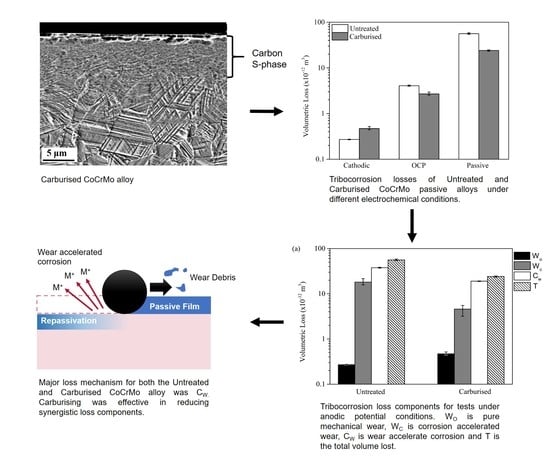
:Tribocorrosion damage is a cause for the premature failure of hip implants made of cobalt-based alloys. Low-temperature carburising can be a plausible solution towards mitigating the tribocorrosion damage of articulating components. This diffusion treatment introduces a supersaturated carbon solid solution, termed S-phase, which hardens the CoCrMo alloy without detriment to the corrosion resistance. This work investigates and compares the tribocorrosion behaviour of untreated and carburised ASTM F1537 CoCrMo alloys tested in Ringer’s solution using a reciprocating sliding configuration against a polycrystalline alumina counterface under different electrochemical conditions. The research shows that whereas the carburised alloy suffered a slightly higher wear loss under a cathodic potential, it was able to reduce the material losses considerably when tested under both open circuit and anodic potential conditions. Under anodic conditions material losses by corrosion due to wear dominated. The better tribocorrosion resistance of the carburised layer was attributed to the better qualities of the passive film for the carburised sample coupled with an increased load support.
1. Introduction
Cobalt-based alloys are widely used for metal-on-metal and polymer-on-metal orthopaedic implants for their good corrosion and wear resistance. However, several investigations report that such alloys still suffer from detrimental corrosion and tribocorrosion damage during their service life within the human body. This leads to several undesired consequences such as toxicity, neurological impairment, and aseptic loosening [1,2,3].
Mischler and Igual Muñoz [4] published an appraisal on the tribocorrosion of CoCrMo alloys in simulated body fluids. The authors conclude that wear induced corrosion from depassivated areas of the scar gravely impacts the overall contact degradation. A wear induced corrosion mechanism which results in a gradual loss of material by the subsequent damage and regeneration of the passive film was termed as Type I corrosion-wear by Dearnley et al. [5]. Despite being generally a mild material loss mechanism, it has been reported as the main source of damage of passive metallic biomaterials when made to slide against inert alumina counterface materials in saline solution [6]. The published literature point towards the synergism constituent of wear induced corrosion as a major contributor to material loss under tribocorrosion scenarios and the importance of the mechanical integrity of the passive layer to limit such damage [4].
The two research teams of Igual Muñoz et al. [7,8,9] and Yan et al. [10,11,12,13,14] conducted numerous investigations on the tribocorrosion of CoCrMo. Igual Muñoz et al. studied the effect of electrochemical potential [7], microstructure [8], and electrolytes [9] on high and low carbon CoCrMo alloy during tribocorrosion against an alumina (Al2O3) counter-face in simulated body fluids at 37 °C. It has been shown that the applied potential and solution chemistry affect the electrochemical properties of the metal-electrolyte interface and the tribocorrosion rate of CoCrMo alloys.
Yan et al. [10,11,13,14] reported that, compared with the low carbon CoCrMo alloy (0.05 wt % C), the high carbon (0.19 wt % C) CoCrMo alloy is less influenced by proteins in terms of the corrosion rate and material degradation. The high carbon CoCrMo alloy performed the best in terms of corrosion-wear loss when testing with proteins against a silicon nitride ball counter-face at 37 °C in two different solutions: Dulbecco’s Modified Eagle’s Medium (DMEM) and 0.36% NaCl solution.
Low-temperature carburising treatment is known to increase the hardness of CoCrMo alloys without any detriment in both static corrosion resistance and biocompatibility [15]. This treatment creates a precipitate-free metastable solid solution of carbon termed S-phase or expanded austenite [16,17]. This layer could potentially augment the corrosion-wear resistance of CoCrMo alloys by enhancing the mechanical integrity of the passive film.
The work conducted by Igual Muñoz et al. and Yan et al. [7,8,9,10,11,12,13,14] focuses on non-surface engineered CoCrMo alloys while very few studies [18] focus on low-temperature carburised CoCrMo alloy in a tribo-corrosion scenario. To this end, corrosion–wear studies of an untreated and carburised CoCrMo alloy sliding against an alumina counterface in Ringer’s solution was studied. This study investigates whether low-temperature carburising is able to mitigate the tribocorrosion damage observed in metal-on-metal CoCrMo implants [1,2,3].
2. Materials and Methods
2.1. Materials and Low-Temperature Carburising Treatment
A wrought low carbon CoCrMo implant metal alloy (ASTM F1537 Standard Specification for Wrought Cobalt-28Chromium-6Molybdenum Alloys for Surgical Implants), with the chemical composition given in Table 1, was used in this work. CoCrMo disc samples were prepared from a 25.4 mm diameter, unannealed ground bar supplied by L. Klein (Biel, Switzerland).
Disc samples with a 6.8 mm thickness were cut from the bar using an electrical-discharge-wire cutting machine. The samples were subsequently ground to obtain flat and parallel disc surfaces. This was followed by sequential manual wet grinding using silicon carbide emery papers, starting with a grit size of 120 up to 1200. The samples were then polished using 6 μm followed by 3 μm diamond pastes (MetPrep, Coventry, UK). A final polishing step, using 0.6 μm colloidal silica suspension (MetPrep, Coventry, UK), was used to achieve the final finish. All samples were ultrasonically cleaned in isopropyl alcohol between the polishing steps. The resultant surface roughness Ra obtained was 0.01 μm, measured by means of an Ambios Xp-200 Stylus Profilometer (Santa Clara, CA, USA).
The polished samples were subjected to a low-temperature carburising diffusion-based surface treatment by Bodycote Hardiff GmbH (Landsberg, Germany). During this diffusion surface treatment, the samples were subjected to temperatures below 500 °C and high carbon potentials for several days to obtain an S-phase layer [15,19]. Following carburising, the surface roughness Ra increased to 0.03 μm. The increase in surface roughness is typically observed following low-temperature carburising [19] during which the microstructure is transformed to an expanded FCC phase and the relaxation of internal stresses generated from the supersaturated solid solution of carbon in austenite occurs. The S-phase layer has been characterised as having extensive microtwins, slip lines and an expansion in the lattice parameter using TEM and XRD [17].
2.2. Electrolyte
The electrolyte used in this research was Ringer’s solution, supplied by Lab M (UK) in tablet form. Eight tablets were dissolved in 1 L of de-ionised water to obtain the Ringer’s solution (9 g L−1 NaCl, 0.42 g L−1 KCl, 0.48 g L−1 CaCl2 and 0.2 g L−1 NaHCO3). Ringer’s solution with a pH of 7.4 and kept at a temperature of 37 °C (±1 °C) provides a good representation of bodily fluids.
2.3. Characterisation of Carburised Layer
Composition depth profiling on the carburised surfaces was performed to establish how the carbon interstitial concentration varied with the distance from the surface using a GDS-750 QDP glow discharge optical emission spectroscopy, GDOES (LECO Corporation, Saint Joseph, MI, USA). The morphology of the carburised layer was characterised using a Zeiss Merlin Gemini II column Field Emission Gun Scanning Electron Microscope, FEG-SEM, (Carl Zeiss AG, Jena, Germany) coupled with an Apollo X Ametek Energy Dispersive Spectroscope, EDS, (Ametek, Berwyn, PA, USA) capability and an optical microscope equipped with a Leica DFC290 digital camera (Leica Microsystems, Wetzlar, Germany). The crystal structure of the carburised layer was determined using a Rigaku Ultima IV X-ray Diffractometer, XRD, (Rigaku, Tokyo, Japan) operated in a Glancing Incidence Angle Asymmetric Bragg (GIAB) configuration. A Mitutoyo MVK-H2 (Mitutoyo, Kawasaki, Japan) equipped with a Vickers hardness indenter (Mitutoyo, Kawasaki, Japan) was used to measure the surface micro-hardness.
2.4. Potentiodynamic Tests
The corrosion behaviour of the untreated and carburised samples was investigated using a Gamry Reference 600™ potentiostat (Gamry, Warminster, PA, USA) that is connected to a three-electrode setup. Further details on the setup can be found in reference [19]. Prior to each test, the samples were ultrasonic cleaned in isopropyl alcohol for 15 min. The sample discs were then tightened against a rubber O-ring which was attached to a flat PTFE holder. The holder provided an exposed area of 177 mm2. Ringer’s solution, maintained at 37 °C (±1 °C), was then added to the cell. The scanning procedure involved 1 h monitoring of the open circuit potential (OCP) followed by a potentiodynamic sweep at a scan rate of 0.176 mV/s between −100 mV vs. OCP and 1000 mV vs. Saturated Calomel Electrode (SCE).
2.5. Tribocorrosion Tests
Tribocorrosion experiments were carried out using a reciprocating sliding tribometer. Details of the tribometer are in reference [19]. A polycrystalline alumina ball (Spheric Trafalgar Ltd., Pulborough, UK) with a diameter of 12.7 mm was made to rub against the moving test sample surface at a set stroke length of 6.5 mm and a frequency of 2 Hz. The alumina ball has a hardness of 1700 HV and is inert in the test environment and therefore, electrochemical measurements during the test reflect the reactions taking place only on the surface of the test sample.
The normal load applied during the tribocorrosion experiments was 8 N. This load results in a maximum shear stress of ~291 MPa which is below the shear yield strength of the untreated CoCrMo alloy (979–986 MPa) and avoids gross plastic deformation of the contact region. The glass container was filled with 300 mL of test solution which was maintained at 37 °C (±1 °C). The electrochemical procedure and parameters were programmed using the Gamry Reference 600™ potentiostat (Gamry, Warminster, PA, USA). An SP22 load transducer (Amber Instruments Ltd., Aldermaston, UK) was calibrated and connected to a computer running a dedicated Labview program to determine the dynamic friction coefficient between the contacting surfaces.
A tribocorrosion investigation was carried out under three different electrochemical conditions. Samples were tested under cathodic, open circuit and passive potential conditions. The metal-electrolyte interface changes with the test potential as follows:
- Cathodic (−700 mV vs. SCE): This potential suppresses metal dissolution and the formation of the passive film and it enables the measurement of material loss via mechanical wear in the absence of corrosion. The material loss is calculated from volume measurements of the resulting scars following tests under cathodic potential conditions;
- OCP: A passive film forms spontaneously on the sample surface. Sliding is expected to mechanically damage and/or remove this self-generating protective layer (Type I corrosion-wear) with an associated drop in potential at which equilibrium of the anodic and cathodic reactions is achieved. The OCP trace is recorded and provides a qualitative insight into the type and extent of electrochemical activity during tribocorrosion testing;
- Passive (100 mV vs. SCE): The passive film forms under this test condition but is damaged or removed by the mechanical action. During testing, the anodic current versus time is recorded. The measured current gives qualitative information on the type of electrochemical damage and is used for the quantitative determination of the material losses via corrosion and corrosion due to wear during tribocorrosion testing using Faraday’s equation.
A 45-min cleaning procedure of each of the test sample surface was applied just before tribocorrosion testing to ensure the uniformity of the surface condition. The test samples were rinsed with soap and water, followed by 15 min of ultrasonic cleaning in isopropyl alcohol and then polished with a 3 μm diamond paste. This was followed by 15 min of ultrasonic cleaning in isopropyl alcohol. The alumina counter-face balls were ultrasonically cleaned for 15 min in acetone before each test.
Initially, the test sample was monitored for 20 min under the test electrochemical condition without sliding. This was followed by two hours of sliding against the alumina ball under the set electrochemical condition. The dynamic frictional force and electrochemical parameters (voltage or current) were measured during sliding. When rubbing was stopped, the worn sample in contact with the electrolyte was left at the test potential for another 20 min. All tests were repeated three times.
The resultant scars on both the alumina balls and disc samples were viewed and analysed using a Zeiss Merlin Gemini II column FEG-SEM couple with an Apollo X Ametek EDS. The cross-sectional area of the wear scar was determined by measuring the cross-section of a wear track using an Ambios Xp-200 Stylus Profilometer (Santa Clara, CA, USA). To obtain the wear volume, the area of the wear scar was calculated using Simpson’s rule and then was multiplied by the length of the wear track. Three locations on each scar were measured to obtain its depth and volume. The average volume lost for each particular test condition was based on three repeats.
3. Results
3.1. S-Phase Layer Characterisation
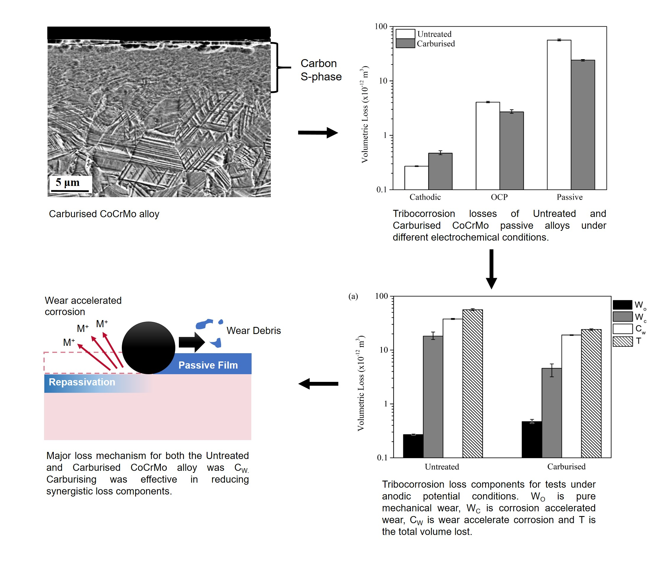
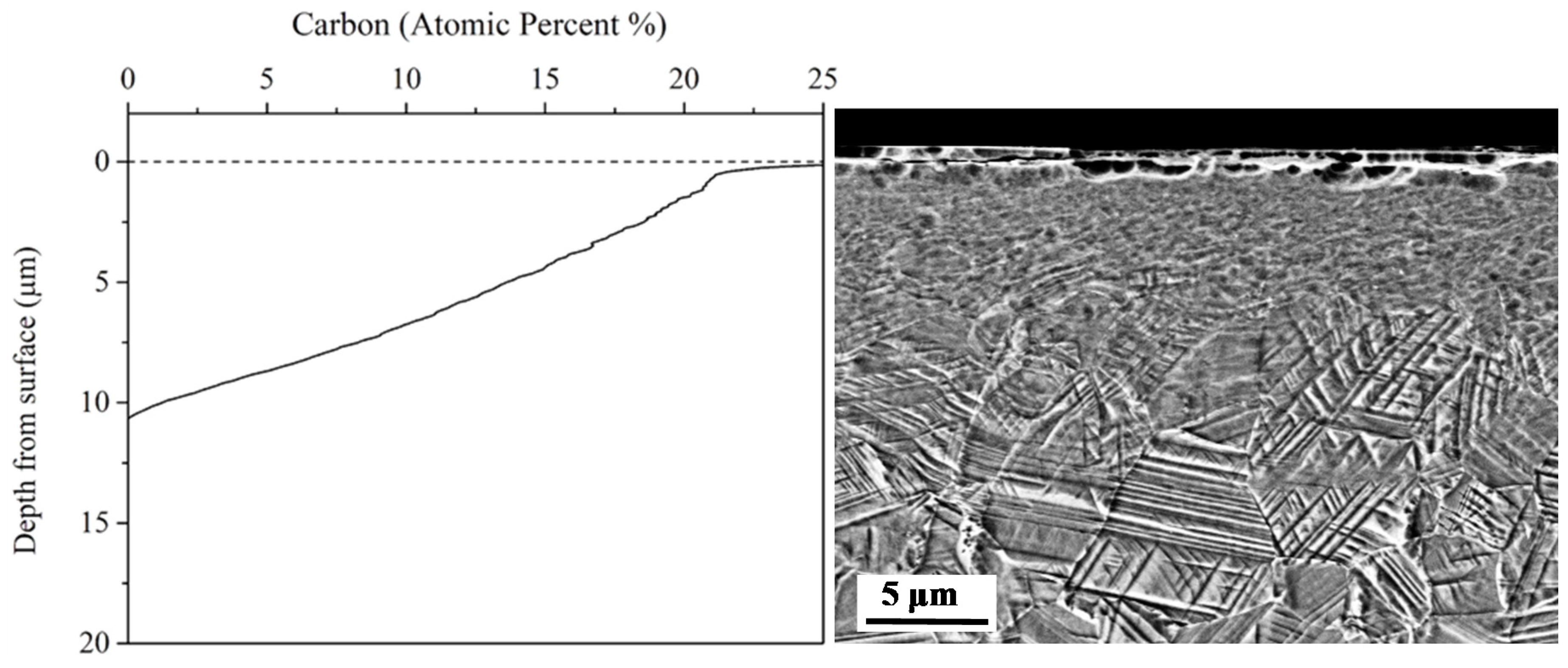
GDOES analysis shows that the carbon interstitial content decreases gradually from 25 at% (~8 wt %) at the surface to the substrate nominal composition within a cross-sectional depth of 10.5 μm (Figure 1). The carbon content of the substrate was 0.05 wt % (Table 1) which was below the detection limit of the GDOES analysis. The cross-sectional SEM image in Figure 1 shows a typical microstructure of a precipitate-free metastable carbon supersaturated solid solution S-phase layer. XRD analysis, shown in Figure 2, revealed broad FCC α-phase peaks shifted to lower angles when compared to the untreated CoCrMo alloy, which is characteristic of an S-phase layer [19]. The S-phase layer had a surface micro-hardness of 962 ± 5 HV0.2 and dropped to 473 ± 3 HV0.2 at a depth of 10.5 μm, which is the hardness of the untreated CoCrMo alloy. The S-phase created by Bodycote Hardiff GmbH (Landsberg, Germany) in this work has the same characteristics as other S-phase layers created in other works [17,18]. A detailed account of the characterisation of the S-phase layer is given in reference [19].
3.2. Potentiodynamic Curves
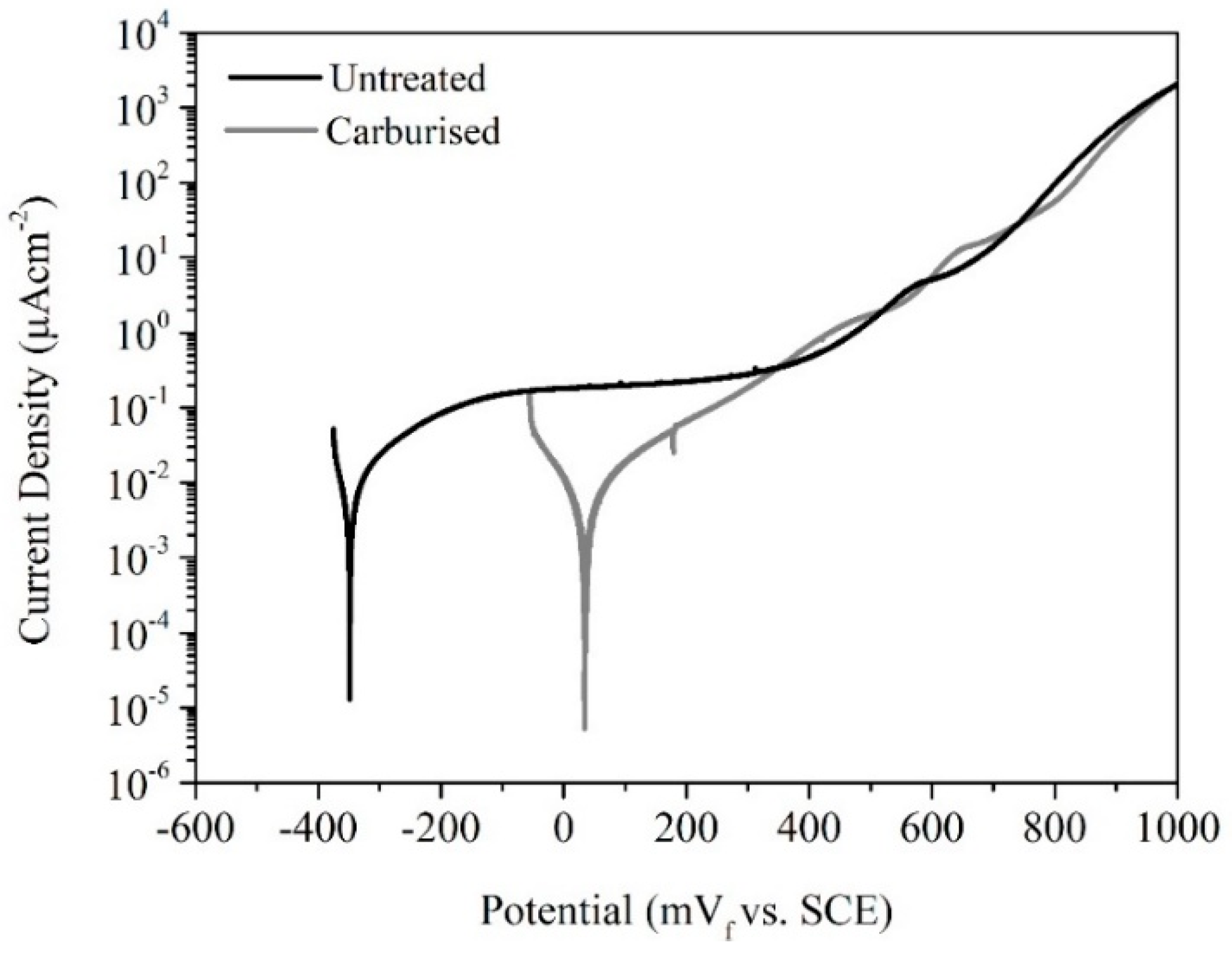
Figure 3 illustrates the potentiodynamic curves for the untreated and carburised samples. It is shown that both samples exhibit an anodic region with a low current density, characteristic of passive materials. Whereas the current density increased to ~0.2 μA/cm2 and stabilised at this value until it reaches a potential of ~400 mV vs. SCE for the untreated CoCrMo, the carburised sample did not exhibit a current plateau. It exhibited a gradual increase in anodic current which reached ~0.2 μA/cm2 at 400 mV vs. SCE. For both materials, the anodic current density kept increasing at a similar rate as the potential was polarised further in the anodic direction. The carburised sample displayed a nobler OCP (~50 mV vs. SCE) when compared to the untreated alloy (~−350 mV vs. SCE).
3.3. Wear Tests under Cathodic Potential Conditions
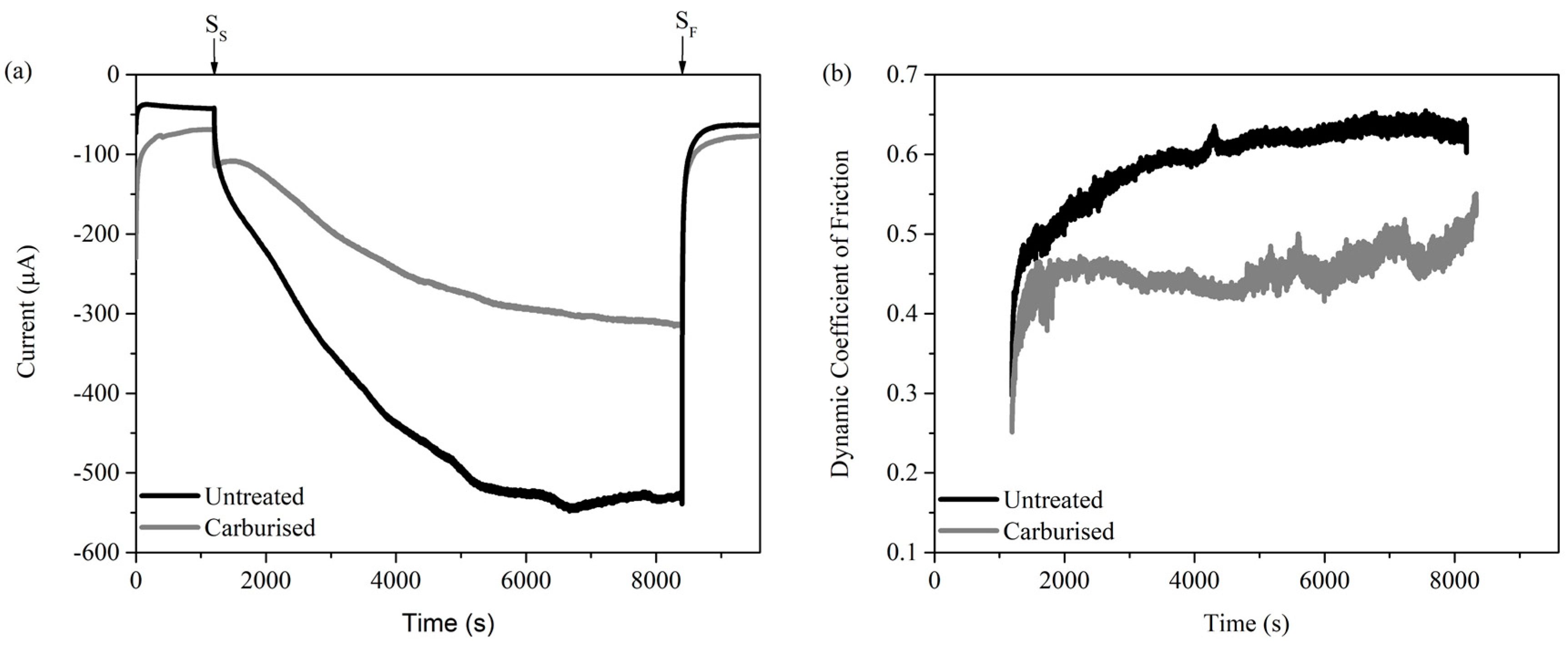
Figure 4a represents a typical cathodic current traces during tribological testing of untreated and carburised CoCrMo alloy under a cathodic potential of −700 mV vs. SCE. Figure 4b depicts the dynamic coefficient of friction against time during the sliding period. The negative cathodic current reflects the predominance of cathodic reactions arising from the test sample surface. An abrupt increase in cathodic current is evident at the onset of sliding. This is followed by a more gradual increase with sliding time. The untreated sample exhibited a higher cathodic current magnitude during sliding. After sliding was stopped, the cathodic current values returned abruptly to similar values measured before the commencement of sliding.
The dynamic friction coefficient of the untreated CoCrMo sample against alumina was higher than that recorded for the carburised sample. It experienced a gradual rise with sliding time and levelled at ~0.65 after about 500 s of sliding. The coefficient of friction of the carburised sample was in the range of 0.4 and 0.5 during the first 1.5 h of sliding and then started to fluctuate and increase slowly till the end of the test, at which point it reached a value of 0.55.
3.4. Tribocorrosion Tests under OCP Conditions
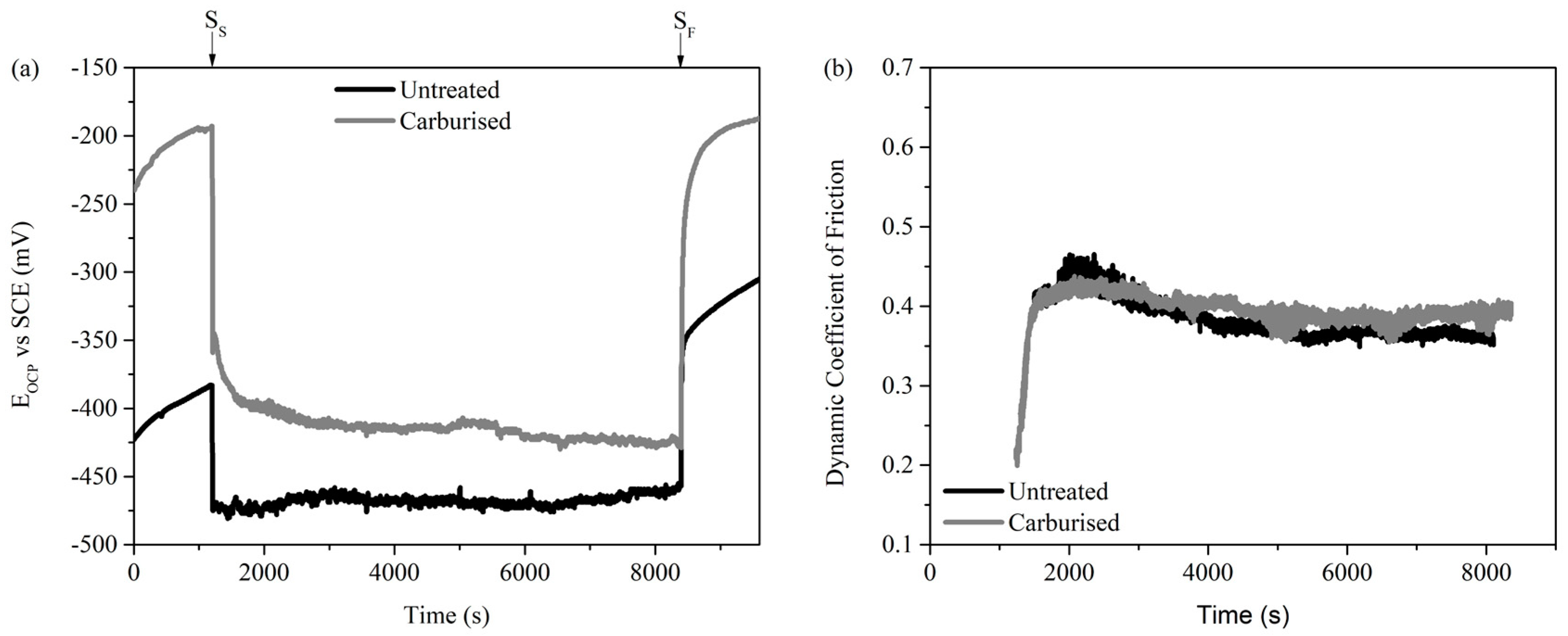
The measured OCP with time traces for tests against untreated and carburised CoCrMo are shown in Figure 5a, while Figure 5b depicts the corresponding dynamic coefficient of friction with time. The OCPs of the untreated and carburised samples prior to sliding are ~−380 mV vs. SCE and ~−200 mV vs. SCE, respectively. When sliding commenced, the OCP of both test samples drops suddenly to more negative values. The plot shows that the equilibrium potential fluctuation during sliding was around 20 mV and no large potential depressions were observed.
The plot of the dynamic coefficient of friction with time is similar for both the untreated and carburised samples. The coefficient of friction increases rapidly during the initial half hour of sliding to ~0.43, after which it decreased slowly to ~0.40.
3.5. Tribocorrosion Tests under Passive Potential Conditions
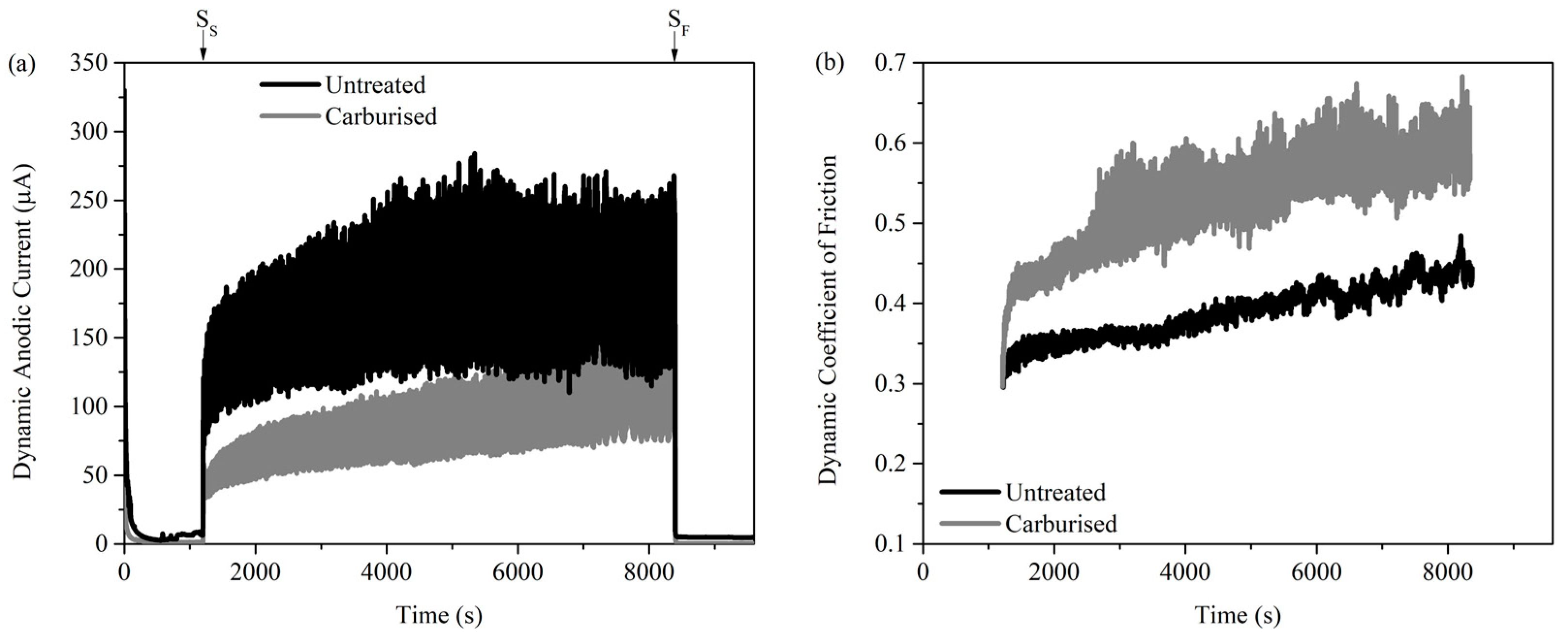
The anodic current versus time traces for tribocorrosion tests under anodic conditions (100 mV vs. SCE) are given in Figure 6a. The corresponding dynamic coefficient of friction traces are shown in Figure 6b. Before the start of sliding, a very small anodic current (~3 μA) was recorded for both the carburised and untreated surfaces. At the onset of sliding both samples experienced an abrupt increase in anodic current. For the untreated sample, an average dynamic anodic current of ~170 μA was recorded. For the carburised sample, an average dynamic anodic current of 85 μA which was around half that of the untreated sample resulted. As sliding was stopped, the anodic current of both samples returned to similar values observed before sliding commenced.
The plots of the dynamic coefficient of friction for both the untreated and carburised samples increase gradually with increasing sliding time. The dynamic coefficient of friction for the carburised sample was higher (0.4–0.65) than that of the untreated sample (0.3–0.45) throughout the sliding period.
3.6. Tribocorrosion Losses
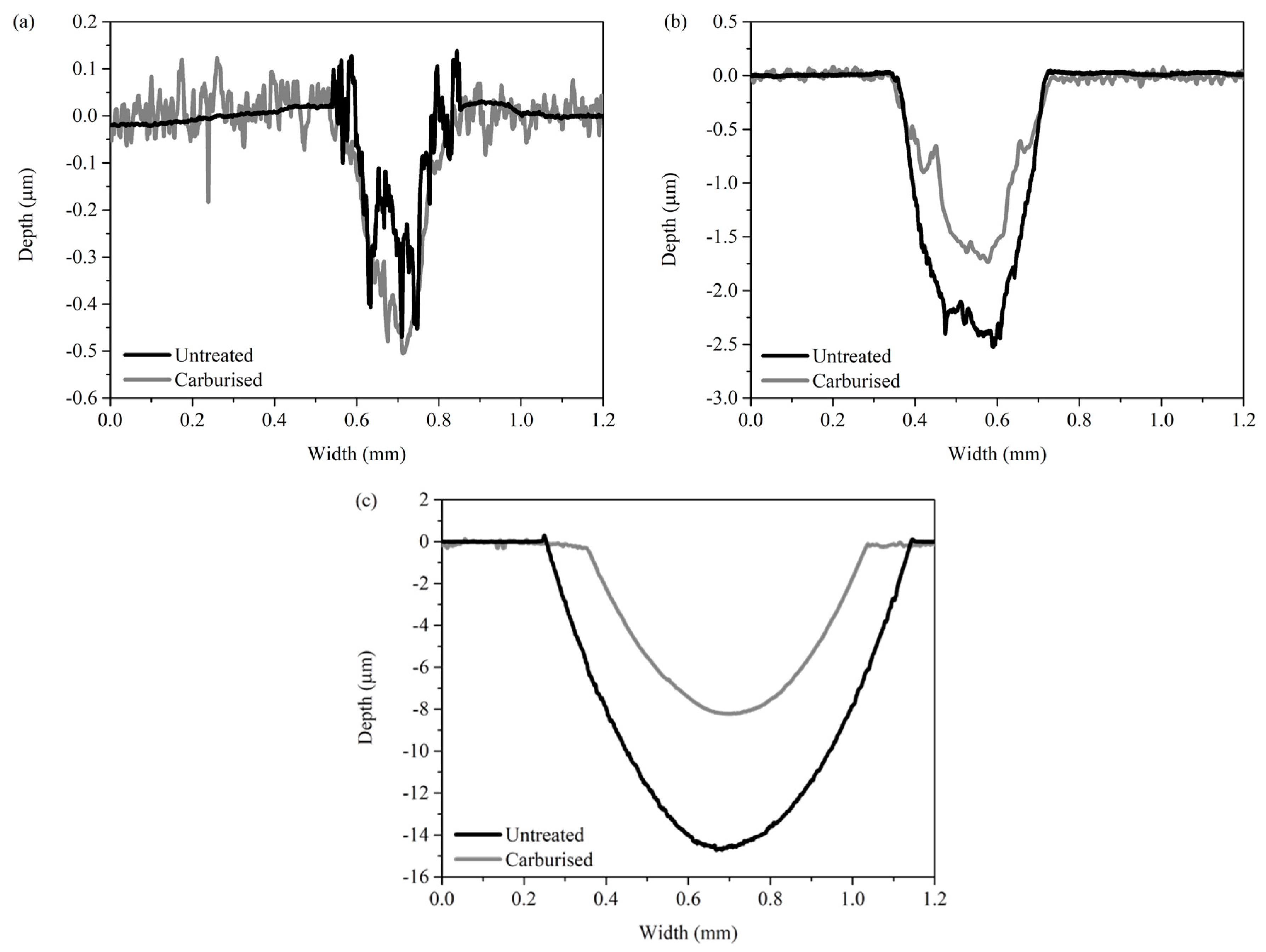
Profiles across the scars for untreated and carburised samples following tribocorrosion testing under cathodic potential are shown in Figure 7a. The resulting scars were only ~0.5 μm deep. The scars were deeper following tribocorrosion testing under OCP conditions, as shown in Figure 7b. The untreated scars were ~2.5 μm deep while the carburised scars were ~1.8 μm deep. For tests under anodic potential conditions, the scars were ~15 μm and ~8 μm deep for the untreated and carburised samples, respectively, as shown in Figure 7c. The scar on the carburised sample scar did not perforate the carburised S-phase layer which was ~10.5 μm in thickness (Figure 1). All wear scar profiles confirm the absence of material pile-ups along the sides of the wear tracks, showing that no gross plastic deformation of the test material occurred and the scar volume represents the material loss during the tests [16].
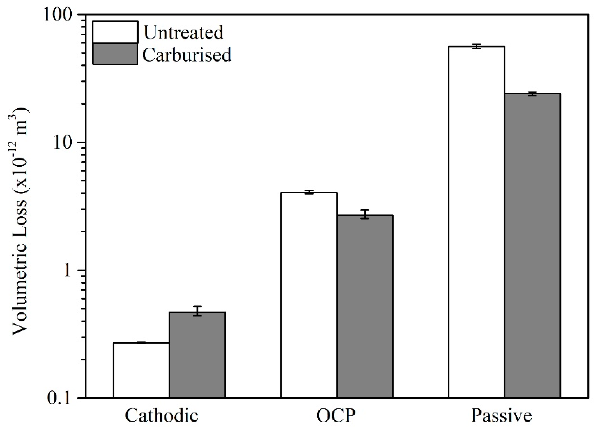
Figure 8 shows the volumetric losses for the untreated and carburised samples following tribological tests under the different electrochemical conditions. The volumetric losses represent an average value of three different wear scars. The volumetric loss was largely dependent on the electrochemical condition and increased in the following order: cathodic potential, OCP, and passive potential conditions (Figure 8). The volumetric loss of the untreated sample is higher compared to the carburised sample under both OCP and passive potential conditions, while under cathodic conditions the carburised sample exhibits a marginally higher volumetric loss than the untreated sample. The volume losses experienced by the alumina balls were negligible and, as such, were unmeasurable.
3.7. Characterisation of Resultant Scars
The scars on ball and disc tribo pairs were viewed under a scanning electron microscope. EDS point analysis was performed on the resultant scars of the test samples and on wear debris collected from the ball scar, by attaching it to carbon tape, immediately after the corresponding tribocorrosion test. The composition of the resultant scars and debris was determined based on an average of three repeated analyses.
3.7.1. Cathodic Potential
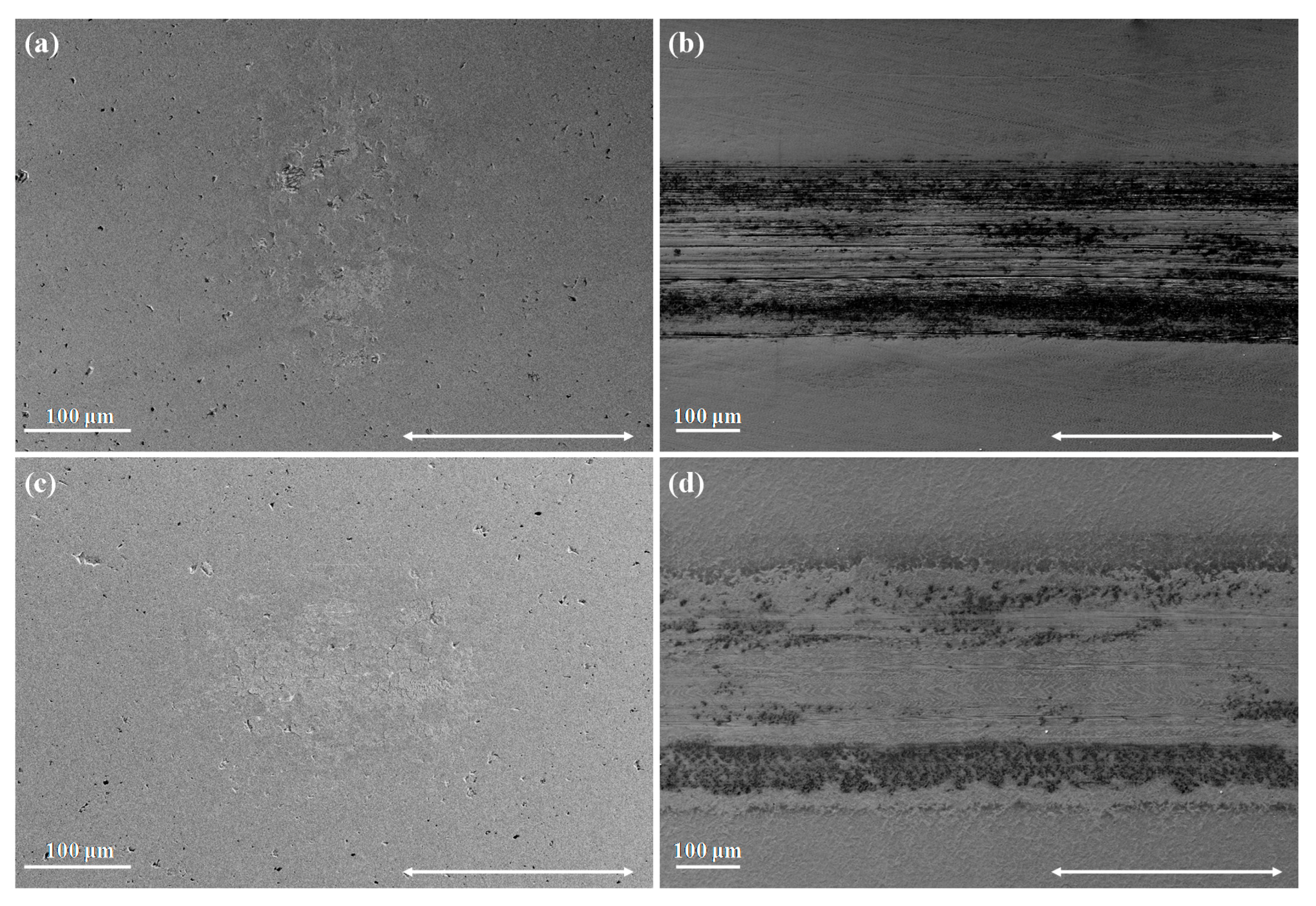
The resultant scars on the alumina ball and untreated CoCrMo disc tribo pair are shown in Figure 9a,b, while those on the alumina ball and carburised CoCrMo disc tribo pair are shown in Figure 9c,d. Damage on the ball sliding contact against untreated CoCrMo, as well as material transfer, were minimal following tests under cathodic potential conditions (Figure 9a). The dark spots scattered all over the contact surface were pre-existing pores within the sintered polycrystalline alumina ball. Figure 9a indicates that some material, viewed as light grey patches, was transferred onto the smooth ball contact surface. The wear transfer layer consisted of cobalt (23.7 wt %) and chromium (10.9 wt %) together with a high oxygen content (36.7 wt %).
Figure 9c depicts the ball scar following sliding against carburised CoCrMo. Here, a small amount of material transfer is evident. The amount of transfer material on the ball is similar to that observed for the untreated sample, as shown in Figure 9a,c. The composition of the debris collected from the ball scar surface consisted of cobalt (24.2 wt %), chromium (11.3 wt %), and a high oxygen content (36.8 wt %). It seems that fine, surface oxidised metallic debris from the carburised sample were smeared onto the smooth ball surface. Their high surface area resulted in a high oxygen content.
The wear scar on the untreated CoCrMo sample after testing under a cathodic potential is primarily characterised by abrasion marks aligned to the sliding direction (Figure 9b). The edges of the wear scar and some regions within the scar are covered by dark patches which comprise fine wear debris. These dark patches had a higher oxygen content than the surrounding areas.
Despite having similar scar dimensions, the abrasion marks are less evident within the scars on the carburised sample (Figure 9d). The resultant scars on the carburised samples were smoother than the untreated samples and contained fewer dark shaded areas along the edges. Here, sliding resulted in the polishing of the carburised surface, as opposed to abrasion experienced by the untreated sample (Figure 9b,d). The dark patches along the edge of the scar contained a high oxygen content (7.6 wt %) when compared to the lighter coloured areas (0.6 wt %), indicating that fine debris which comprised oxidised metal particles were present within these dark patches.
3.7.2. OCP
The resultant scars on the untreated and carburised discs and the corresponding alumina balls following tribocorrosion testing under OCP conditions are shown in Figure 10a–d. The alumina ball scar exhibited minimal damage and had a smooth smeared transfer layer following the sliding against the untreated CoCrMo sample. The transfer layer collected from the alumina scar consisted of cobalt (16.5 wt %), chromium (12.5 wt %), and a high oxygen content (35.9 wt %). The transfer layer seems to have a metallic character as it was smeared on the surface but comprised of fine surface oxidised debris, which explains the high oxygen content. The middle region also contains minor ball damages in the form of depressions which are not comparable to the pores resulting from the sintering process. This might indicate that material from the ball was detached during sliding by a grain pull-out mechanism.
The ball scar following sliding against carburised CoCrMo is shown in Figure 10c. Here, a transfer layer having cracks and loosely attached to the ball is observed. This transfer layer comprised of cobalt (7.2 wt %), chromium (16.6 wt %), and a high oxygen content (39.1 wt %).
A high density of thin abrasion marks characterises the scar on the untreated material, shown in Figure 10b. Fine debris was present within the abrasion marks and along the scar edges. The regions appeared darker on the SEM image and contained a higher oxygen content (8.5 wt %) when compared to the rest of the scar. For the carburised sample, the resultant wear scars contained very mild abrasion marks, as shown in Figure 10d. In this case, sliding primarily resulted inpolishing wear of the carburised surface. Similar to the untreated sample, the dark-coloured regions on the SEM image, shown in Figure 10d, had a high oxygen content (8.1 wt %).
3.7.3. Passive Potential
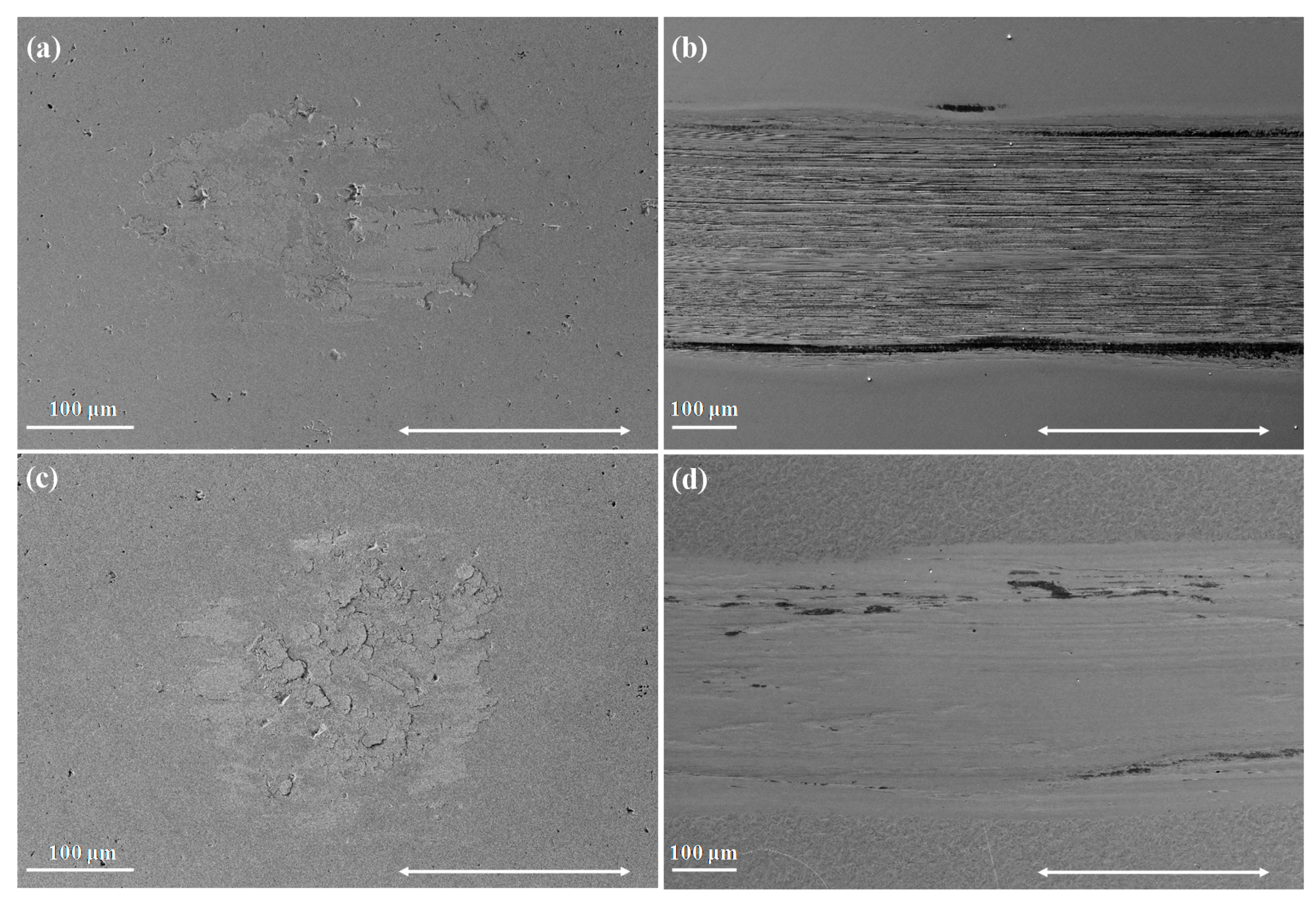
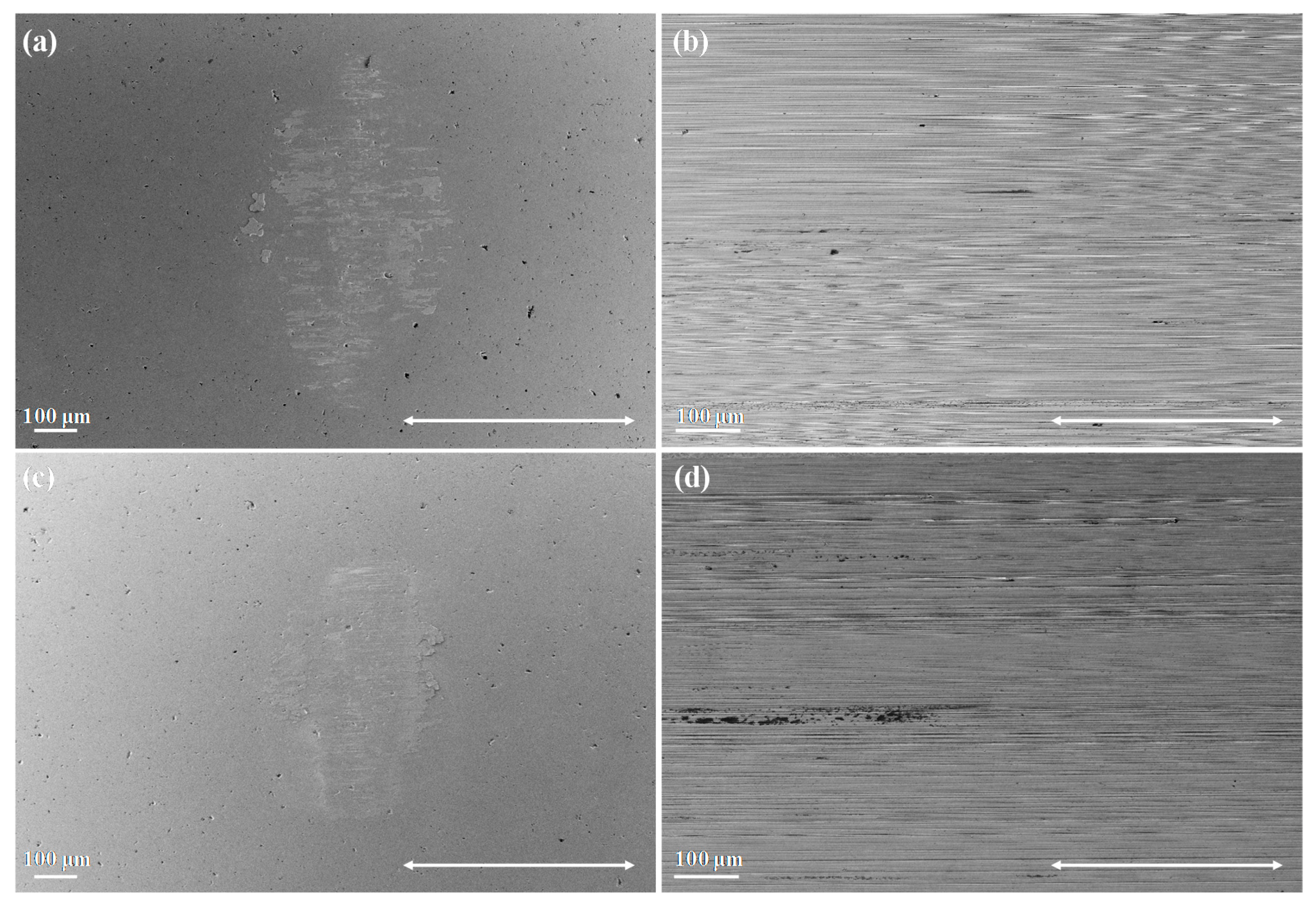
The resultant scars on the untreated and carburised disc samples and corresponding alumina balls following testing under anodic potential conditions are shown in Figure 11a–d. Similar to tests carried out under cathodic and OCP conditions, minimal damage was observed on the alumina ball sliding surface against the untreated sample. The scar on the ball, shown in Figure 11a, following sliding against the untreated CoCrMo alloy was partly covered by a smooth transferred material layer, which was composed of cobalt (12.3 wt %), chromium (25.3 wt %), and a high oxygen content (31.9 wt %).
The shape and topography of the ball scar following sliding against carburised CoCrMo, shown in Figure 11c, is similar to that observed following rubbing against untreated CoCrMo, shown in Figure 11a. The composition of the transfer layer consisted of cobalt (2.9 wt %), chromium (19.8 wt %), and a high oxygen content (33.6 wt %).
The resultant scars for both the untreated (Figure 11b) and carburised samples (Figure 11d) following tests under passive potential are much wider compared to the other two potentials and their scar morphology is largely identical. The scar morphology is characterised by fine abrasion lines aligned in the direction of sliding. Fine debris particles were probably trapped in the sliding contact or attached to the counter-body during sliding. The presence of an established passive film onto the metal surface greatly reduced particle adhesion onto the ball as it prevented direct contact between alumina and CoCrMo [18].
At this potential, the wear mode of both surface conditions is similar. This may have been a consequence of the fact that the depth of the resultant scar on the carburised surface is comparable to the thickness of the carburised layer. At this depth, the hardness becomes similar to the untreated CoCrMo alloy due to the greatly reduced interstitial content (refer to Figure 1 and Figure 7). Nonetheless, the S-phase layer was still successful in reducing the wear-enhanced corrosion component as shown by the lower dynamic anodic current in Figure 6 and the smaller wear scar.
4. Discussion
4.1. Material Loss Dependence on the Electrochemical Potential
The total volumetric wear loss experienced by both the untreated and carburised samples during tribocorrosion testing (Figure 8) was strongly dependent on the test’s electrochemical potential. A thicker passive film formed at the anodic potential (100 mV vs. SCE) is expected to increase the losses associated with the damage or removal and regeneration of the passive film, also known as Type I corrosion-wear [5]. The review paper by Mischler and Igual Muñoz [4] on the tribocorrosion of CoCrMo alloys used in metal-on-metal hip joints states that a rapid increase in material loss rate corresponds to the potential at which the thickening of the passive film present on CoCrMo accelerates. In addition to the increased material losses via Type I corrosion-wear, the passive film is known to increase the mechanical wear due to the large accumulation of dislocations in the wear track promoting subsurface cracking and limiting plastic flow [4,20]. In a separate study by Bazzoni et al. [21], the authors attribute the tribocorrosion enhancement of plasma-nitrided CoCrMo samples to the lack of a passive film when tested under anodic potentials, using an alumina ball as a counter-face in 0.9 wt % NaCl. On the other hand, in this work, despite retaining its passive characteristics, the carburised CoCrMo sample was effective in limiting the losses under anodic potential conditions when compared to untreated CoCrMo (Figure 8). This could have been due to an enhanced load support brought about by the higher hardness of the underlying S-phase which better supports the passive film, and superior passive film characteristics of the carburised sample, namely the higher impedance and lower time constant dispersion when compared to the untreated alloy. The better load support and passive film characteristics of the carburised sample, which were characterised by Cassar et al. [22], were somewhat different to that of the untreated CoCrMo alloy and have positively contributed to the lower losses. This result shows that the carburised alloy could be resistant to general corrosion while still displaying superior tribocorrosion behaviour when compared to the untreated CoCrMo alloy. The results of this work are in contrast with reference [21], where improved tribocorrosion performance was achieved at the expense of passivity.
4.1.1. Volumetric Loss under Cathodic Potential Conditions
The carburised sample resulted in a similar volumetric loss to that experienced by the untreated CoCrMo alloy under cathodic potential conditions (Figure 8). Despite the similar material loss rates, the wear modes experienced by the untreated and carburised CoCrMo samples were different. The untreated CoCrMo alloy exhibited mild abrasions as evidenced by the aligned abrasion marks in the direction of sliding, shown in Figure 9b. The carburised CoCrMo sample exhibited a much smoother wear track with minor evidence of abrasion marks, indicating that polishing wear was dominating, as shown in Figure 9d. The main difference at this potential is the smoother polished surface that results on the carburised surface following sliding. The carburised surface had a higher hardness compared to the untreated surface (962 ± 5 HV0.2 vs. 473 ± 3 HV0.2, respectively). Therefore, it was expected to yield lower abrasion losses compared to the softer CoCrMo alloy. The untreated CoCrMo alloy retained sufficient plasticity inhibiting subsurface cracking and associated losses, resulting in low mechanical wear. The formation of transfer layers on the alumina balls sliding against the untreated and carburised samples contained an oxidised material which is more abrasive to the softer untreated sample. The amount of transfer material was small and no significant damage to the alumina ball surface was observed. Still, this may have resulted in the micro-abrasion damage of the untreated CoCrMo sample and polishing of the carburised surface.
4.1.2. Volumetric Loss under OCP and Passive Potential Conditions
The carburised sample was effective to lower the volumetric loss of CoCrMo both under OCP and even more under passive potential (100 mV vs. SCE) conditions (Figure 8). A reduction of 34% and 57% in volumetric losses were recorded for tests on carburised CoCrMo when compared to the untreated CoCrMo alloy and carried out under OCP and anodic potential conditions, respectively. The higher hardness of the carburised sample and lower dynamic anodic current (Figure 6a) recorded during the sliding of the polarised carburised CoCrMo explain the resulting lower material loss (Figure 8). It is hypothesised that the passive film characteristics of the carburised sample, together with the higher hardness of the carburised surface, have played a role in the reduction of volumetric loss compared to the untreated CoCrMo alloy.
In fact, EIS experimentation on identical CoCrMo samples [22] following sliding under both OCP and passive potential conditions revealed a higher impedance (thus, a better protection of the metal) and a lower time constant dispersion of the passive film on the carburised CoCrMo when compared to the untreated sample. A more tenacious passive film promotes ceramic-to-ceramic sliding contact and a lower material loss [18,22]. The improved passive film impedance coupled with the ability to better withstand mechanical damage through the support of the underlying hard S-phase enhances the performance of carburised CoCrMo during tribocorrosion [22].
Luo et al. [18] recorded similar volumetric losses for the untreated and carburised CoCrMo samples under OCP, but attained a greatly reduced wear loss at passive potentials of −250 mV, 0 mV, and 400 mV vs. SCE, conforming with the results obtained in this investigation.
SEM imaging (Figure 9b, Figure 10b and Figure 11b) revealed that the untreated CoCrMo sample displayed abrasion marks following sliding under all the test electrochemical conditions. On the contrary, the harder carburised sample displayed polishing wear under cathodic potential and OCP conditions (Figure 9d and Figure 10d). In case of tests under anodic potential conditions (Figure 11d), the scar depth (Figure 7c) showed that the carburised layer was almost consumed (Figure 1) and abrasion marks were evident in the wear scar.
4.2. Material Loss Components
Tests under anodic potential conditions enable the quantification of the mechanical and corrosion components of the material loss. The synergistic approach was used to identify the material loss components for tests carried out under passive potential conditions (100 mV vs. SCE). The total volume of material lost, T, is defined by Equation (1):
where WO is the loss due to wear only, CO is the loss due to corrosion only and S is the loss resulting from the synergism between wear and corrosion. The synergism comprises both wear-enhanced corrosion (CW) and corrosion-enhanced wear (WC), so that
The value of corrosion only (CO) is very small for passive alloys like CoCrMo, and was assumed to be negligible. Faraday’s law was used to calculate the volumetric loss due to wear-enhanced corrosion, CW, shown in Equation (3):
where I is the average anodic current recorded during sliding minus the initial current (i.e., without sliding). The sliding duration period, t, was 7200 s and Faraday constant, F, is 96,485 C/mol. The valence of the alloy, n, was estimated by considering the oxidation valence of the alloying elements, together with their percentage content. Only the metallic elements, Co, Cr, and Mo, are assumed to participate in the oxidation reactions. The oxidation valences of Co, Cr, and Mo were assumed to be 2, 3, and 4 [23], respectively, and the content of the respective elements within the alloy are 65, 28, and 5.5 wt % (Table 1). The overall oxidation valence (n) of the untreated and carburised alloy used in this work was of 2.36.
The atomic mass, M, of the alloy was calculated by multiplying the weight percent content of each element within the alloy by the element’s atomic mass, and summing up all the constituent atomic masses. The resulting atomic mass (M) of the untreated and carburised alloy was 58.64 g/mol. The density (ρ) of both samples was assumed to be 8.29 g/cm3. The density of the untreated and carburised samples was assumed to be the same since the higher carbon concentration in the S-phase layer is being accommodated by a lattice expansion. Moreover, the carbon concentration profile changes with depth from the surface so any changes in density which are expected to be small, vary with layer cross section. Therefore, the density of the S-phase layer was assumed to be equal to that of the untreated substrate.
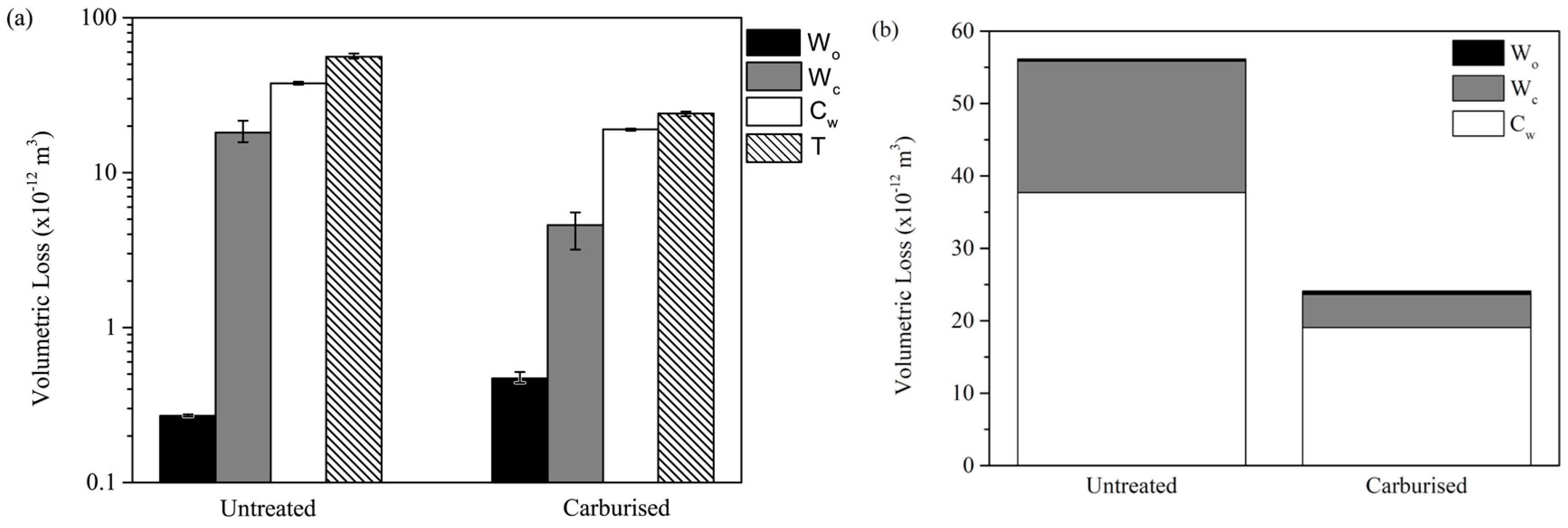
The material loss components for the untreated and carburised samples are given in Figure 12. The contribution of WO to the total volumetric loss was assumed to be the total volumetric loss for tests carried out under cathodic potential conditions. This is based on the assumption that by suppressing the anodic electrochemical activity, the mechanical wear component is not significantly affected. This assumption has its limitations since as Mischler [24] states “wear under cathodic potential cannot be considered as an absolute reference for wear in absence of corrosion”. In this study, WO was very small when compared to the other material loss components. Since T, CW, and WO are all known, the volumetric loss due to the synergistic factor corrosion-enhanced wear, WC, was calculated using Equations (1) and (2).
Wear-enhanced corrosion (CW) was the dominant material loss component for both the untreated and carburised CoCrMo samples (Figure 12), in agreement with Mischler and Igual Muñoz [4] who state that wear-enhanced corrosion may be the major contributor of the total loss in the ultimate application of CoCrMo replacement joints. Wear-enhanced corrosion is dominated by stripping the surface from its passive film when made to slide against the alumina counter-face material (Type I corrosion-wear) [5]. As soon as rubbing commences, a marked increase in anodic current resulted (Figure 6a). This behaviour is synonymous with the passive film being damaged or removed and regenerated. The metal in the active part of the wear scar is bare and hence subjected to direct contact with the electrolyte leading to an increased corrosion.
The actual value of wear loss associated with CW is significantly lower in the carburised metal compared to the untreated metal (Figure 12). This might be a consequence based on the hypothesis that the carburised sample has improved passive film impedance and mechanical stability, as described in reference [22], as well as to the better load support of the underlying S-phase.
The other synergistic constituent, corrosion-enhanced wear (WC), also contributes significantly to the total material loss (Figure 12). The untreated CoCrMo alloy exhibits a high corrosion-enhanced wear (WC), compared to WO, despite the material loss mechanism via mechanical wear remained that of micro-abrasion and the counter-face scar morphology was similar. The material loss mechanism by mechanical wear is evident in Figure 9b, Figure 10b, and Figure 11b where the tracks contained micro-abrasion marks. Similar to tests under cathodic protection, the untreated CoCrMo wear tracks did not display delamination-type failure or micro-cracking. Hence, it is likely that WC resulted from an increase in micro-abrasion damage due to the more efficient removal of work hardened layers via corrosion-dominated tribocorrosion processes. For the carburised alloy, the WC was smaller than that exhibited by the untreated CoCrMo alloy, yet still, it was a considerable loss. In this case, the mechanism of mechanical wear changed from polishing under cathodic potential conditions to micro-abrasions despite the similar scar morphologies on the counter-face. The change in wear mechanism explains the higher mechanical losses exhibited under anodic potential conditions. This behaviour was due to the removal of the harder top part of the S-phase layer exposing softer material in the contact zone. This would have yielded lower abrasion resistance to hard oxidised debris and counter-face asperities as evidenced in Figure 11d. In addition, the anodic environment influences the formation mechanism and physical properties of metallic debris during sliding, and also, the electrochemical process these undergo to form third bodies [25,26]. For instance, the oxidation of debris in the wear track makes these particles harder and consequently more damaging during rubbing. Nonetheless, the carburised sample was effective in significantly reducing WC when compared to the untreated sample (Figure 12).
In general, the synergism between corrosion and wear was the major phenomenon causing a material loss in both the untreated and carburised samples, with a contribution of 99.5% and 98.0%, respectively. This observation is supported by Watson et al. [27], who point out that the synergism between wear and corrosion is expected to be more pronounced on passive metals such as the ones investigated in this work.
5. Conclusions
The following conclusions are based on tribocorrosion tests obtained under a normal applied load of 8 N in Ringer’s solution at 37 °C (±1 °C) against an alumina ball counter-face under cathodic (−700 mV vs. SCE), OCP, and passive (100 mV vs. SCE) potential conditions:
- The carburising of CoCrMo alloy was successful in lowering the tribocorrosion losses under both equilibrium and passive potential conditions. A similar volumetric loss was observed under cathodic potential conditions for both untreated and carburised CoCrMo samples.
- Under cathodic potential and OCP conditions, the morphology of the wear tracks produced on untreated CoCrMo was predominantly characterised by abrasion marks, as opposed to polishing wear experienced by the carburised CoCrMo alloy.
- Under anodic potential conditions, the morphology of wear tracks produced on the untreated and carburised samples was similar and comprised of fine micro-abrasion marks aligned with the direction of sliding. Tribocorrosion processes have resulted in the removal of almost the entire S-phase layer exposing a softer material with mechanical properties more similar to the untreated CoCrMo alloy.
- Synergism between corrosion and wear constituted 99.5% and 98.0% of the loss associated with the untreated and carburised CoCrMo samples, respectively.
- The improvement in corrosion-wear, CW (the dominant material loss component), of the carburised alloy was attributed to the better qualities of the passive film of the carburised sample coupled with an increased load support when compared to the untreated CoCrMo alloy.
Author Contributions
Conceptualization: B.M. and J.B.; Methodology: J.C. and A.K.; Formal Analysis: J.C., B.M. and J.B.; Investigation: J.C.; Resources: A.K.; Data Curation: J.C. and A.M.; Writing-Original Draft Preparation: J.C., A.M., B.M. and J.B.; Writing-Review and Editing: A.M., B.M. and J.B.; Supervision: B.M. and J.B.; Project Administration: B.M. and J.B.; Funding Acquisition: A.M.
Funding
This research was partially funded by the ENDEAVOUR Scholarships Scheme [ESF.03.015]. The scholarship is part-financed by the European Union–European Social Fund (ESF) under Operational Programme II–Cohesion Policy 2007–2013, “Empowering People for More Jobs and a Better Quality of Life”.
Acknowledgments
The authors are also grateful for financial support received by the University of Malta Research Fund. The authors would also like to thank ERDF (Malta) for financing the testing equipment through the project: “Developing an Interdisciplinary Material Testing and Rapid Prototyping R&D Facility (Ref. no. 012)”.
Conflicts of Interest
The authors declare no conflicts of interest.
References
- Campbell, J.R.; Estey, M.P. Metal release from hip prostheses: Cobalt and chromium toxicity and the role of the clinical laboratory. Clin. Chem. Lab. Med. 2012, 51, 213–220. [Google Scholar] [CrossRef] [PubMed]
- Smith, A.J.; Dieppe, P.; Vernon, K.; Porter, M.; Blom, A.W. Failure rates of stemmed metal-on-metal hip replacements: Analysis of data from the National Joint Registry of England and Wales. Lancet 2012, 379, 1199–1204. [Google Scholar] [CrossRef]
- Gill, H.S.; Grammatopoulos, G.; Adshead, S.; Tsialogiannis, E.; Tsiridis, E. Molecular and immune toxicity of CoCr nanoparticles in MoM hip arthroplasty. Trends Mol. Med. 2012, 18, 145–155. [Google Scholar] [CrossRef] [PubMed]
- Mischler, S.; Muñoz, A.I. Wear of CoCrMo alloys used in metal-on-metal hip joints: A tribocorrosion appraisal. Wear 2013, 297, 1081–1094. [Google Scholar] [CrossRef] [Green Version]
- Dearnley, P.A.; Aldrich-Smith, G. Corrosion-wear mechanisms of hard coated austenitic 316L stainless steel. Wear 2004, 256, 491–499. [Google Scholar] [CrossRef]
- Dearnley, P.A.; Mallia, B. The chemical wear (corrosion-wear) of novel Cr based hard coated 316L austenitic stainless steel in aqueous saline solution. Wear 2013, 306, 263–275. [Google Scholar] [CrossRef]
- Igual Muñoz, A.; Casabán Julián, L. Influence of electrochemical potential on the tribocorrosion behaviour of high carbon CoCrMo biomedical alloy in simulated body fluids by electrochemical impedance spectroscopy. Electrochim. Acta 2010, 55, 5428–5439. [Google Scholar] [CrossRef]
- Casabán Julián, L.; Igual Muñoz, A. Influence of microstructure of HC CoCrMo biomedical alloys on the corrosion and wear behaviour in simulated body fluids. Tribol. Int. 2011, 44, 318–329. [Google Scholar] [CrossRef]
- Igual Muñoz, A.; Mischler, S. Effect of the Environment on Wear ranking and Corrosion of Biomedical CoCrMo Alloys. J. Mater. Sci. Mater. Med. 2011, 22, 437–450. [Google Scholar] [CrossRef] [PubMed]
- Yan, Y.; Neville, A.; Dowson, D. Tribo-corrosion properties of cobalt-based medical implant alloys in simulated biological environments. Wear 2007, 263, 1105–1111. [Google Scholar] [CrossRef] [Green Version]
- Yan, Y.; Neville, A.; Dowson, D.; Williams, S. Tribocorrosion in implants—Assessing high carbon and low carbon Co–Cr–Mo alloys by in situ electrochemical measurements. Tribol. Int. 2006, 39, 1509–1517. [Google Scholar] [CrossRef]
- Yan, Y.; Neville, A.; Dowson, D.; Williams, S.; Fisher, J. Effect of metallic nanoparticles on the biotribocorrosion behaviour of Metal-on-Metal hip prostheses. Wear 2009, 267, 683–688. [Google Scholar] [CrossRef]
- Yan, Y.; Neville, A.; Dowson, D. Biotribocorrosion of CoCrMo orthopaedic implant materials—Assessing the formation and effect of the biofilm. Tribol. Int. 2007, 40, 1492–1499. [Google Scholar] [CrossRef]
- Yan, Y.; Dowson, D.; Neville, A. In-situ electrochemical study of interaction of tribology and corrosion in artificial hip prosthesis simulators. J. Mech. Behav. Biomed. Mater. 2013, 18, 191–199. [Google Scholar] [CrossRef] [PubMed]
- Caligari Conti, M.; Karl, A.; Schembri Wismayer, P.; Buhagiar, J. Biocompatibility and characterization of a Kolsterised® medical grade cobalt-chromium-molybdenum alloy. Biomatter 2014, 4, 1–10. [Google Scholar]
- Dong, H. S-phase surface engineering of Fe-Cr, Co-Cr and Ni-Cr alloys. Int. Mater. Rev. 2010, 55, 65–98. [Google Scholar] [CrossRef]
- Li, X.Y.; Habibi, N.; Bell, T.; Dong, H. Microstructural characterisation of a plasma carburised low carbon Co–Cr alloy. Surf. Eng. 2007, 23, 45–51. [Google Scholar] [CrossRef]
- Luo, X.; Li, X.; Sun, Y.; Dong, H. Tribocorrosion behavior of S-phase surface engineered medical grade Co–Cr alloy. Wear 2013, 302, 1615–1623. [Google Scholar] [CrossRef]
- Cassar, J.; Mallia, B.; Karl, A.; Buhagiar, J. EIS of carburised CoCrMo: Evolution of parameters characterising the metal-electrolyte interface. Surf. Coat. Technol. 2016, 292, 90–98. [Google Scholar] [CrossRef]
- Bidiville, A.; Favero, M.; Sadelmann, P.; Mischler, S. Effect of surface chemistry on the mechanical response of metals in sliding tribocorrosion systems. Wear 2007, 263, 207–217. [Google Scholar] [CrossRef]
- Bazzoni, A.; Mischler, S.; Espallargas, N. Tribocorrosion of pulsed plasma-nitrided CoCrMo implany alloy. Tribol. Lett. 2013, 49, 157–167. [Google Scholar] [CrossRef]
- Cassar, J.; Mallia, B.; Karl, A.; Buhagiar, J. The effect of sliding onto the metal-electrolyte interface: Studying model parameter modifications by means of EIS. Mater. Sci. Eng. C 2017, 75, 1366–1375. [Google Scholar] [CrossRef] [PubMed]
- Hodgson, A.W.E.; Kurz, S.; Virtanen, S.; Fervel, V.; Olsson, C.O.A.; Mischler, S. Passive and transpassive behaviour of CoCrMo in simulated biological solutions. Electrochim. Acta 2004, 49, 2167–2178. [Google Scholar] [CrossRef]
- Mischler, S. Triboelectrochemical techniques and interpretation methods in tribocorrosion: A comparative evaluation. Tribol. Int. 2008, 41, 573–583. [Google Scholar] [CrossRef]
- Landolt, D.; Mischler, S.; Stemp, M.; Barril, S. Third body effects and material fluxes in tribocorrosion systems involving a sliding contact. Wear 2004, 256, 517–524. [Google Scholar] [CrossRef]
- Jemmely, P.; Mischler, S.; Landolt, D. Electrochemical modelling of passivation phenomena in tribocorrosion. Wear 2000, 237, 63–76. [Google Scholar] [CrossRef]
- Watson, S.W.; Friedersdorf, F.J.; Madsen, B.W.; Cramer, S.D. Methods of measuring wear-corrosion synergism. Wear 1995, 181–183, 476–484. [Google Scholar] [CrossRef]
Figure 1.
The carbon concentration profile within the S-phase layer and the corresponding scanning electron microscope image of an etched carburised CoCrMo cross-section showing an S-phase layer of 10.5 μm in thickness.
Figure 1.
The carbon concentration profile within the S-phase layer and the corresponding scanning electron microscope image of an etched carburised CoCrMo cross-section showing an S-phase layer of 10.5 μm in thickness.

Figure 2.
The Glancing Angle XRD (3° angle of incidence) diffraction patterns for the untreated and carburised samples. The broadening and shift to lower angles of the α(111) and α(200) show the formation of the S-phase layer. X-ray source: CuKα radiation.
Figure 2.
The Glancing Angle XRD (3° angle of incidence) diffraction patterns for the untreated and carburised samples. The broadening and shift to lower angles of the α(111) and α(200) show the formation of the S-phase layer. X-ray source: CuKα radiation.

Figure 3.
The potentiodynamic curves for the untreated and carburised samples in Ringer’s solution.

Figure 4.
(a) The current against time and (b) Dynamic coefficient of friction traces for wear tests under cathodic potential (−700 mV vs. SCE) conditions. SS and SF represent the start and finish of sliding, respectively.
Figure 4.
(a) The current against time and (b) Dynamic coefficient of friction traces for wear tests under cathodic potential (−700 mV vs. SCE) conditions. SS and SF represent the start and finish of sliding, respectively.

Figure 5.
(a) The open circuit potential with time and (b) Dynamic coefficient of friction traces for tribocorrosion tests carried out under OCP conditions. SS and SF represent the start and finish of sliding, respectively.
Figure 5.
(a) The open circuit potential with time and (b) Dynamic coefficient of friction traces for tribocorrosion tests carried out under OCP conditions. SS and SF represent the start and finish of sliding, respectively.

Figure 6.
(a) The current against time and (b) Dynamic coefficient of friction traces for tribocorrosion tests under passive potential (100 mV vs. SCE) conditions. SS and SF represent the start and finish of sliding, respectively.
Figure 6.
(a) The current against time and (b) Dynamic coefficient of friction traces for tribocorrosion tests under passive potential (100 mV vs. SCE) conditions. SS and SF represent the start and finish of sliding, respectively.

Figure 7.
The scar profiles on disk samples following tribocorrosion tests under (a) cathodic potential (−700 mV vs. SCE); (b) OCP and; (c) passive potential (100 mV vs. SCE) conditions.
Figure 7.
The scar profiles on disk samples following tribocorrosion tests under (a) cathodic potential (−700 mV vs. SCE); (b) OCP and; (c) passive potential (100 mV vs. SCE) conditions.

Figure 8.
The total volumetric wear loss for untreated and carburised samples during tribocorrosion tests under different electrochemical conditions. The error bars represent the maximum and minimum values of three readings, with respect to the average value. Note that the total volumetric wear loss is on a log scale.

Figure 9.
Secondary electron SEM images of wear scars produced under cathodic polarisation (−700 mV vs. SCE) conditions: (a) alumina ball scar tested against untreated CoCrMo; (b) untreated CoCrMo disc wear scar; (c) alumina ball scar tested against carburised CoCrMo; (d) carburised CoCrMo disc wear scar. Arrows indicate the direction of sliding.

Figure 10.
Secondary electron SEM images of wear scars produced during tests under OCP conditions: (a) alumina ball scar tested against untreated CoCrMo; (b) untreated CoCrMo disc wear scar; (c) alumina ball scar tested against carburised CoCrMo; (d) carburised CoCrMo disc wear scar. Arrows indicate the direction of sliding.

Figure 11.
Secondary electron SEM images of wear scars produced under passive polarisation (100 mV vs. SCE) conditions: (a) alumina ball scar tested against untreated CoCrMo; (b) untreated CoCrMo disc wear scar; (c) alumina ball scar tested against carburised CoCrMo; (d) carburised CoCrMo disc wear scar. Arrows indicate the direction of sliding.

Figure 12.
(a) Tribocorrosion volumetric losses calculated through the synergistic approach (note the use of logarithmic scale); (b) Summation of synergistic constituents: corrosion-enhanced wear (WC) and wear-enhanced corrosion (CW). The error bars represent the maximum and minimum values of three readings, with respect to the average value. Note that WC is obtained from the manipulation of average values of the other parameters and its error is the summation of all the individual parameter errors.


Table 1.
The chemical composition of ASTM F1537 CoCrMo alloy.
| Composition (wt %) | ||||||||||||
|---|---|---|---|---|---|---|---|---|---|---|---|---|
| C | Mn | Si | P | S | Cr | Ni | Mo | Cu | N | W | Fe | Co |
| 0.05 | 0.80 | 0.62 | 0.003 | 0.0005 | 27.64 | 0.07 | 5.46 | 0.01 | 0.169 | 0.02 | 0.2 | Bal. |
© 2018 by the authors. Licensee MDPI, Basel, Switzerland. This article is an open access article distributed under the terms and conditions of the Creative Commons Attribution (CC BY) license (http://creativecommons.org/licenses/by/4.0/).
Share and Cite
MDPI and ACS Style
Cassar, J.; Mallia, B.; Mazzonello, A.; Karl, A.; Buhagiar, J. Improved Tribocorrosion Resistance of a CoCrMo Implant Material by Carburising. Lubricants 2018, 6, 76. https://doi.org/10.3390/lubricants6030076
AMA Style
Cassar J, Mallia B, Mazzonello A, Karl A, Buhagiar J. Improved Tribocorrosion Resistance of a CoCrMo Implant Material by Carburising. Lubricants. 2018; 6(3):76. https://doi.org/10.3390/lubricants6030076
Chicago/Turabian StyleCassar, Josianne, Bertram Mallia, Antonino Mazzonello, Andreas Karl, and Joseph Buhagiar. 2018. "Improved Tribocorrosion Resistance of a CoCrMo Implant Material by Carburising" Lubricants 6, no. 3: 76. https://doi.org/10.3390/lubricants6030076
Note that from the first issue of 2016, this journal uses article numbers instead of page numbers. See further details here.