Article

Combined Analytical and Experimental Evaluation of Frictional Performance of Lubricated Untextured and Partially Textured Sliders

Wolfson School of Mechanical, Electrical and Manufacturing Engineering, Loughborough University, Loughborough, Leicestershire LE11 3TU, UK
*
Author to whom correspondence should be addressed.
Lubricants 2018, 6(4), 88; https://doi.org/10.3390/lubricants6040088
Submission received: 3 August 2018 / Revised: 30 August 2018 / Accepted: 7 September 2018 / Published: 1 October 2018
(This article belongs to the Special Issue Tribological Performance of Textured Surfaces)

Abstract

:
The study of textured surface performance is one of the highly researched topics in recent times. This is mainly due to the advantages that such surfaces can potentially provide in practice, in mitigating adverse tribological conditions, such as friction and wear. However, considering the complexities found in practice, a methodological analysis and evaluation procedure is essential in order to gain an understanding of the benefits from utilising such features in a given contact. The current study provides a combined analytical and experimental approach towards an enhanced understanding of the behaviour of textured surfaces relative to their untextured counterparts. The developed analytical models are invaluable in providing an insight into the relationship between the many parameters involved in defining even simple surface texture feature geometry and the expected outcomes in practice, when corroborated with experimental results. The current study reports on such an endeavour. With the studied texture configuration, the results have shown the possibility of reducing friction by as much as 25%.

1. Introduction

Since the reintroduction of the concept of artificially textured surfaces into tribological contacts in the late 1990’s by Etsion et al. [1,2] and later by Burstein and Ingman [3], this area of research has attracted significant attention. This brief introduction does not intend to provide an exhaustive review of literature, but mainly highlight a few studies which are particularly relevant to the subject matter of the current study.
Ronen et al. [4] and Rahmani et al. [5] have considered the effect of textured surfaces in contacts, representing piston ring-to-cylinder liner conjunction under hydrodynamic regime of lubrication. The latter included comparison of the infinite width and finite width textures of various shapes in both positive (convex) and negative (concave) profiles. The result showed that textured surfaces enable better control of lubricant film thickness in an engine cycle. The effect of surface texturing in boundary, mixed, and mixed-elastohydrodynamic regimes of lubrication have also been investigated by Petterson and Jacobson [6], Zavos and Nikolakopoulos [7], and Krupka and Hartl [8]. The work in Reference [6] concludes that the performance of textured surfaces is highly dependent on the operating conditions, particularly in a boundary regime of lubrication, whilst the sensitivities of the results to the size and shape of micro-features in elastohydrodynamic (EHL) contacts in rolling and sliding kinematic conditions have been highlighted in Reference [8]. The effect of introducing texture features on cylinder liners, as an example of sliding contact conditions has also been explored by Morris et al. [9,10] and Garbon et al. [11]. Relatively, marginal improvements have been reported in References [8,9] in terms of friction reduction mainly due to the rather complex conditions existing in the piston ring-liner conjunction. For instance, it was shown in Reference [9] that the lubricant retained in the created micro-reservoirs in the conjunctional inlet can alter the extent of effective micro-wedge effect, which is critically dependent on the lubricant supply. The textured surfaces used in Reference [11] were in the form of the cross-hatched, honed cylinder liners, where the honing angle of texture features is shown to be an important parameter. Tala-Igjhil et al. [12], Morris et al. [13,14], and Lin et al. [15] considered the use of textured surfaces in journal bearings. The work in Reference [12] shows that a fully textured pattern is ineffective in generating hydrodynamic load carrying capacity, whilst the partially textured pattern was shown to be more effective, in line with reported works in the literature. The results in Reference [12] also showed that in the environment of a journal bearing contact, due to relative complexity, the studied partially textured patterns exhibit quite low improvements, whilst the fully textured patterns proved to be rather detrimental. The experimental work in Reference [13] followed by a combined experimental and numerical approach based on computational fluid dynamics (CFD) analysis in Reference [14], also showing marginal improvements from by the textured surfaces, highlighting the requirement for an in-depth optimisation of textured surfaces for specific applications. The work of Lin et al. [15] in line with the findings of Tala-Igjhil et al. [12] signify the importance of optimal positioning of the texture features, based on the expected pressure distribution pattern in the contact to accrue maximum benefits.
Surface texture features can take various forms, depending on the method of fabrication. For example, Etsion [16] used a laser surface texturing (LST) technique to produce micro-pores with application in various sliding conjunctions. Brizmer et al. [17] conducted a numerical study, evaluating the performance of micro-pore features in sliding contacts, implemented on flat surfaces with the potential use in parallel thrust bearings. The work highlighted the improved performance of partially textured surfaces and the potential for optimisation of the features. Kligerman et al. [18] used a similar methodology to investigate the effect of partial texturing in piston ring applications, where the ring segments were of flat profile. Ryk and Etsion [19] also explored the use of symmetric partially textured rings in an experimental study, where the texture features were implemented on flat surfaces with chamfered ends in the axial direction. They also reported that partially textured barrelled ring contact face profiles produced no significant improvements. Through analytical/numerical work Rahmani [20], also showed that the performance of textured surfaces may diminish in the presence of any other surface topographical feature such as the existence of a specific form, particularly of parabolic shape. There are many other works related to the study of the textured surfaces, including the optimisation of features in order to attain some maximum measure of performance. In the particular case of asymmetric partially textured surfaces, related to the current work, further details can be found in Rahmani and Rahnejat [21].
Performance measures of interest for textured surfaces are improved load carrying capacity and reduced friction, oil loss and leakage. Various percentages improvements in these measures have been reported in the literature under certain experimental and/or numerically analysed conditions, depending on the shape, type and distribution of textures, as well as the prevalent regime of lubrication [22]. In the current study an attempt was made to create two samples with similar geometrical profiles, where one was textured, whilst the other remained untextured. Then, their performance in terms of generated friction under given operating conditions was ascertained. Additionally, analytical models were developed in order to compare the predictions with measurements. This was with the intention of shedding some light upon the level of complexity required in predicting the performance of textured surfaces, as well as benchmarking their advantages. Furthermore, the importance of this work relies on unifying and validating the developed and existing analytical methodologies for both textured and untextured surfaces. An important aim is to understand the mathematical relationships between the bearing performance and associated geometrical features. This can help explaining the observed performance of textured surfaces and provide guidance for optimisation of contacts performance.

2. Experimental Setup and Procedure

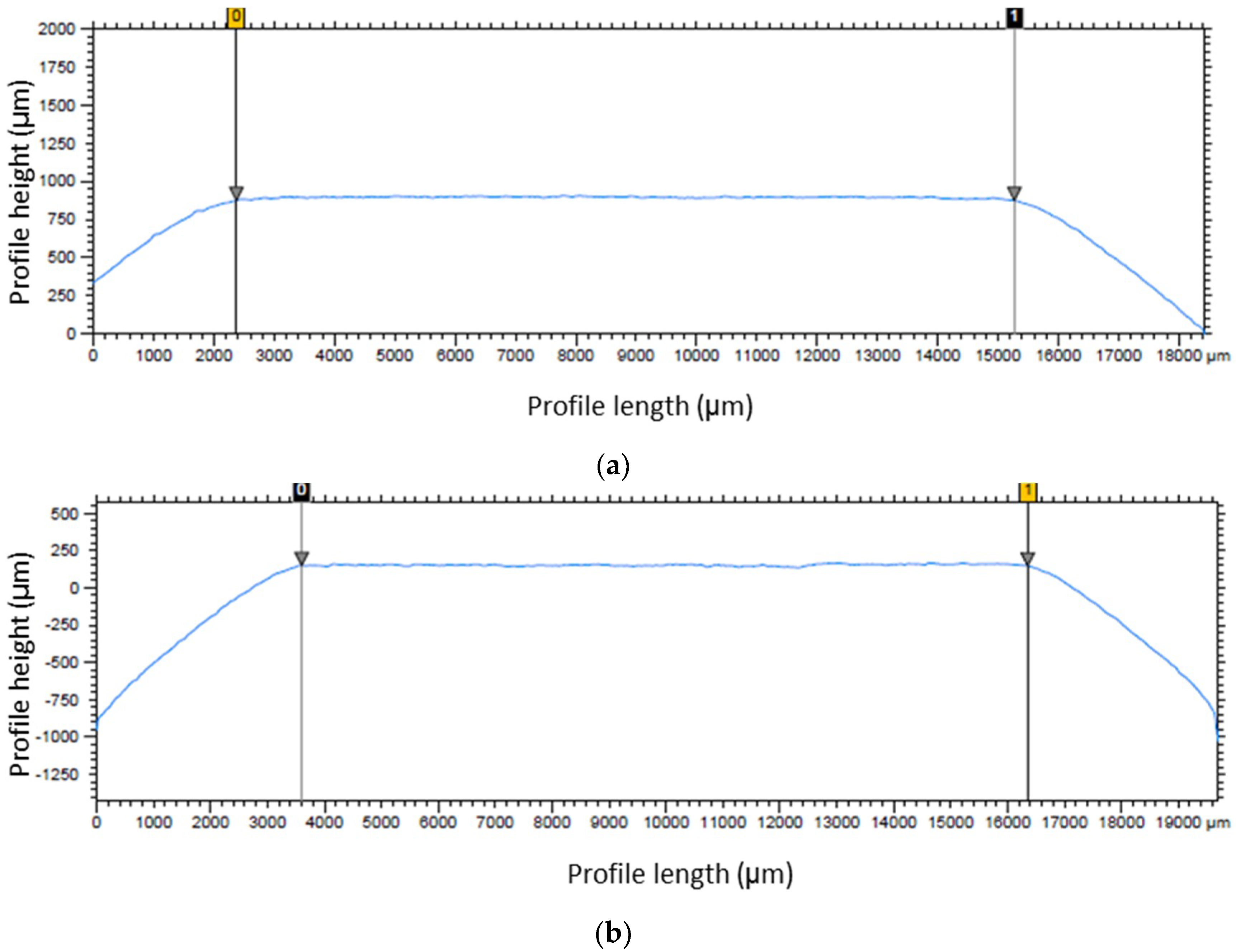
2.1. Preparation of Samples
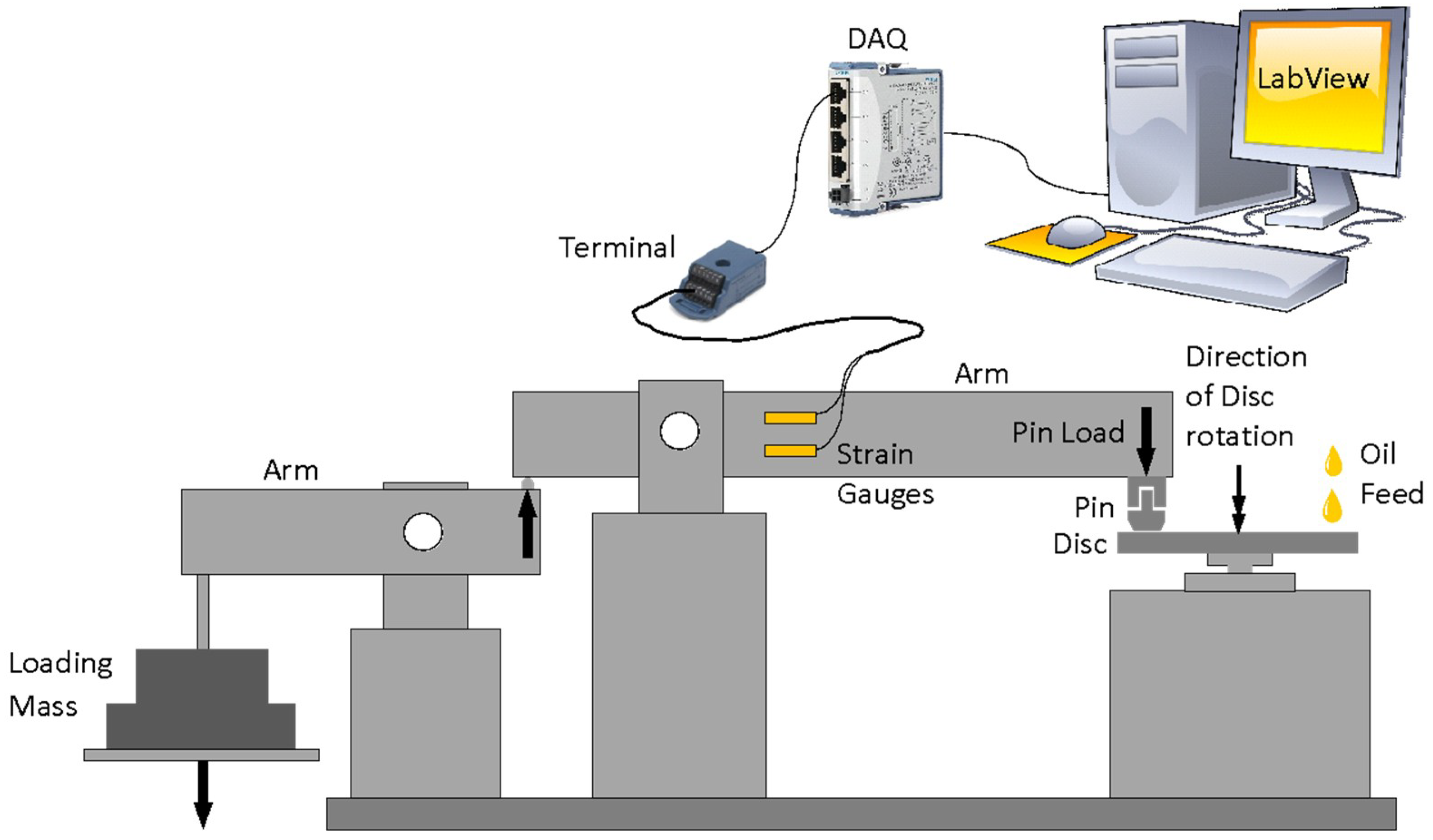
Two sliders were manufactured from EN36C steel stock. The sliders had symmetric wedges (chamfers) in the direction of entrainment where the lubricant inlet meniscus and outlet rupture boundary reside. The middle section of the slider was ground to a flat profile with specific surface roughness. As is shown in the literature (e.g., [2,4,12,20]) the performance of fully textured surfaces was expected to be inferior to that of partially textured ones. Thus, a partial textured pattern was chosen for this study. As is shown in Reference [20], this is due to the breakdown of pressure as a result of cavitation occurring at each individual texture, unlike the case for partially textured contacts, where the pressure at each texture feature builds up on top of the generated pressure perturbation at a preceding texture. One of the samples was partially textured on its flat contacting face using a Struers DuraScan hardness testing machine. This machine can indent the surface with equidistant textures of pyramid geometry. This provides texture features with triangular cross-section, enabling the use of available relationships in the literature for predicting the tribological performance of such texture features. The counter-face disc sample was also made of EN36C steel with a ground surface to remove any remaining wear scars prior to each new test.
The profile of the sliders was measured by a micrometre precision Talysurf CLI-2000 profilometer. The measured profiles are shown in Figure 1.
White light interferometry was used to characterise the textured pattern (Figure 2a). The cross-sectional profile of a single texture pattern is shown in Figure 2b. The average maximum depth and width of the textured profiles were 35 and 380 μm, respectively. The standard deviation in repeatability of the texture features were 3.24 and 6.56 μm, respectively.
The choice of the textures size and distribution were based on the provided charts for geometrical parameters concerning optimum partial textured surfaces in Reference [21], also considering the practical aspects of producing texture features which are repeatable and provide sufficient geometrical resolution.
The mechanical and topographical properties of the slider and disc are listed in Table 1. The slider samples were polished using a Buehler grinder-polisher in order to reduce any sharp edges on the flat surface of the slider which can induce higher friction and wear through ploughing action. The dimensions given in Table 1 are for an overall slider cross-section (length × width) and the disc diameter.

2.2. Test Procedure

Pin-on-disc tribometry is widely used to investigate the tribological performance of various contacts. An in-house pin-on-disc tribometer was utilised to study the effect of surface textures on the frictional losses of the lubricated conjunctions (see Figure 3). The apparatus was designed, based on the ASTM G99 and DIN 50,324 standards [23,24] for friction and wear studies. A constant DC voltage was supplied to an inverter control unit using a signal generator and the output signal rotated the disc through an AC induction motor. The attainable average sliding velocities at the measured track in the pin-on-disc tribometer were in the range of 0.1 to 12 m/s. The pin sample was attached to the loading cantilever arm equipped with the Wheatstone-bridge strain gauge rosettes. The strain gauges were calibrated to convert the bending deflection of the arm into measured friction. The bridge offset error was kept below 1% and the signal was recorded in LabView interface using National Instrument cDAQ-9178 chassis and NI-9237 module. Further information on this particular tribometer can be found in References [25,26,27].
All experiments were carried out in conformance with the ASTM standards for measurement of friction. All experiments were carried out at the room temperature (20 °C). A 15W40 fully formulated lubricant was utilised for all experiments. The lubricant dynamic viscosity was 0.287 Pa.s at room temperature. A constant flow rate injector pump with flow rate of 35 mm/h with a 10 cc syringe was utilised to feed the lubricant to the contact inlet. Lubricant flow rate was set in a way that an ample supply existed at the inlet meniscus (a flooded inlet). The surface topographies of the slider and disc samples were investigated before and after each experiment in order to ensure that no significant wear occurs. The variations in the surface roughness were noted to be negligible for the combined load-velocity operating conditions in this study. The rotational speed of the disc was varied in the range 100–400 RPM (equivalent to sliding velocities of 0.55–2.19 m/s) in incremental steps of 100 RPM. The contact load through the slider was varied in the range 4.94–19.76 N (equivalent to 38.29–153.18 kPa contact pressures) in steps of 4.94 N. Friction was recorded for 30 s after an initial running-in period and the measured data was deemed to have reached steady state conditions. Each experiment was repeated at least three times to ensure the repeatability of the results. The measured friction data from the test rig in time were processed based on the procedure described in Reference [25] in order to obtain the average coefficient of friction. This includes ignoring the data under the initial transient part of the measurements and considering the data from the steady state conditions, were the measured friction remains almost constant.
Based on the developed analytical methods, explained in the next section, the operating conditions were carefully selected in order to maintain the conditions required for attainment of hydrodynamic regime of lubrication with a plenteous minimum film. Nevertheless, the surface samples were inspected visually after each test to make sure that there were no visible wear scars on their surfaces. In addition, representation of the measured and calculated data using a Stribeck graph, based on the Hersey parameter, should follow a known trend, depending on the prevalent regime of lubrication. In a hydrodynamic regime of lubrication, it was expected that the measured and calculated coefficients of friction increase with a rise in the speed of sliding.

3. Analytical Model

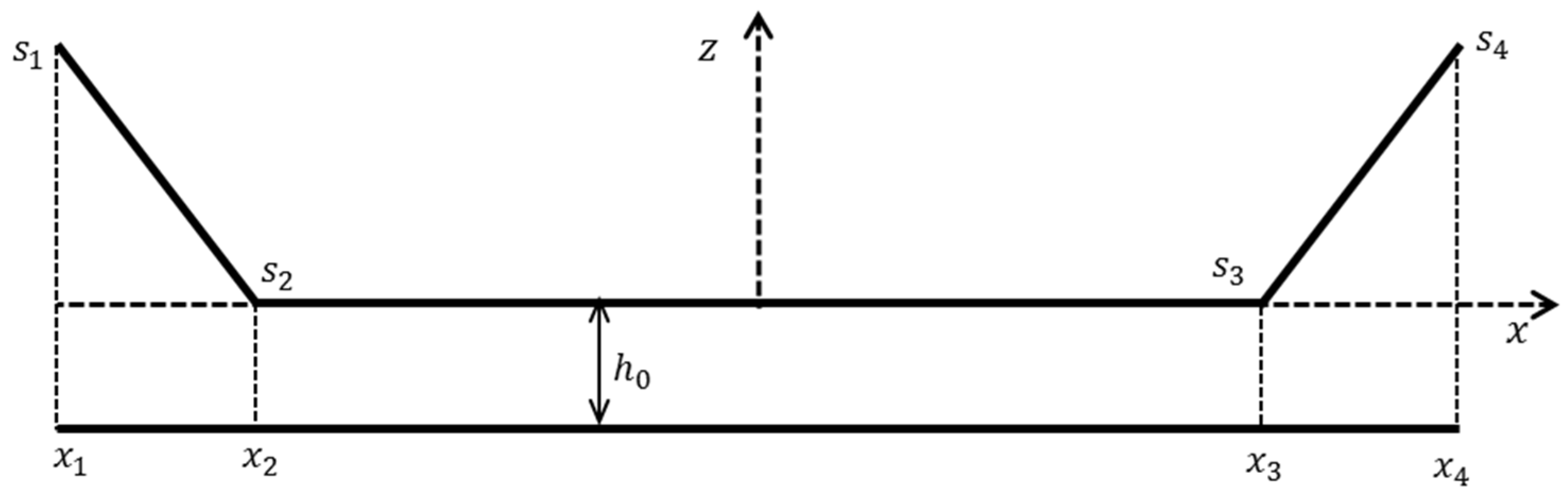
3.1. Untextured Slider

The steady-state incompressible iso-viscous one-dimensional Reynolds equation can be written as [28]:
x ( h 3 p x 6 η U h ) = 0  
Defining the dimensionless parameters:
x ¯ = x L ,   h ¯ = h h 0 , p ¯ = p h 0 2 η U L  
The dimensionless form of the equation can be expressed as:
x ¯ ( h ¯ 3 p ¯ x ¯ 6 h ¯ ) = 0  
The dimensionless pressure distribution is obtained through double integration of the dimensionless Reynolds equation with respect to x ¯ , thus:
p ¯ = 6 1 h ¯ 2 d x ¯ + C 1 1 h ¯ 3 d x ¯ + C 2  
Atmospheric pressure is considered at the inlet meniscus for the slider-on-disc configuration, hence C 2 = 0 . At the cavitation inception point (lubricant film rupture) at the contact outlet, the pressure gradient diminishes, using the Reynolds boundary condition [28], thus:
d p ¯ d x ¯ | x ¯ = x ¯ c = 6 h ¯ c 2 + C 1 1 h ¯ c 3 = 0  
Resulting in C 1 = 6 h ¯ c . In addition, the pressure at the cavitation inspection point should be equal to the cavitation pressure, which is assumed to be equal to the atmospheric pressure in this study. Thus:
x ¯ 1 x ¯ c 1 h ¯ 2 d x ¯ = h ¯ c x ¯ 1 x ¯ c 1 h ¯ 3 d x ¯  
Solving this equation with respect to x ¯ c will provide the location of lubricant film rupture (outlet boundary). Figure 4 shows the schematic representation of the untextured slider profile.
Thus, the contact made by the chamfered slider, in dimensionless form, can be expressed as:
h ¯ = 1 + { s ¯ 1 x ¯ 1 x ¯ 2 ( x ¯ x ¯ 2 )            x ¯ [ x ¯ 1 , x ¯ 2 ] 0                                  x ¯ ] x ¯ 2 , x ¯ 3 [ s ¯ 4 x ¯ 4 x ¯ 3 ( x ¯ x ¯ 3 )            x ¯ [ x ¯ 3 , x ¯ 4 ]
Considering the above slider profile and as the cavitation is expected to occur in the divergent part of the contact, substituting Equation (7) into (6) and performing the associated integrations results in:
x ¯ 2 x ¯ 1 1 + s ¯ 1 + x ¯ 3 x ¯ 2 + ( x ¯ 4 x ¯ 3 ) ( x ¯ c x ¯ 3 ) s ¯ 4 ( x ¯ c x ¯ 3 ) + ( x ¯ 4 x ¯ 3 ) = ( 1 + s ¯ 4 x ¯ c x ¯ 3 x ¯ 4 x ¯ 3 ) { 1 2 ( x ¯ 2 x ¯ 1 ) ( 2 + s ¯ 1 ) ( 1 + s ¯ 1 ) 2 + x ¯ 3 x ¯ 2 + 1 2 ( x ¯ 4 x ¯ 3 ) ( x ¯ c x ¯ 3 ) [ s ¯ 4 ( x ¯ c x ¯ 3 ) + 2 ( x ¯ 4 x ¯ 3 ) ] [ s ¯ 4 ( x ¯ c x ¯ 3 ) + ( x ¯ 4 x ¯ 3 ) ] 2 }
For a symmetric profile, if s ¯ 1 = s ¯ 4 = 1 ξ , where ξ is considered to be the chamfer height ratio, and placing the centre of the coordinate system at the centre of the profile, then: x ¯ 1 = 1 / 2 ,   x ¯ 4 = + 1 / 2 ,   x ¯ 2 = λ ,   x ¯ 3 = λ ,   where   0 < | λ | < 1 / 2 , solutions for Equation (8) can be obtained. The following solution is deemed as acceptable owing to the problem configuration in the current study and the expected limitation, including: x ¯ c > 0 :
x ¯ c = 16 λ 2 ξ 2 ( ξ 1 ) + 2 λ 1 + ξ ( 2 λ 1 ) 2 ( 8 λ 2 ξ 2 8 λ 2 ξ + 4 λ ξ + 4 λ 2 4 λ + 1 ) 2 ( 8 λ ξ 3 12 λ ξ 2 + 2 ξ 2 + 2 λ 1 )  
Therefore, the dimensionless pressure distribution is given as:
p ¯ ( x ¯ ) = 6 { x ¯ 1 x ¯ 1 h ¯ 1 2 d x ¯ h ¯ c x ¯ 1 x ¯ 1 h ¯ 1 3 d x ¯ ,                                                                                              x ¯ [ x ¯ 1 , x ¯ 2 [     x ¯ 1 x ¯ 2 1 h ¯ 1 2 d x ¯ + x ¯ 2 x ¯ 1 h ¯ 2 2 d x ¯ h ¯ c ( x ¯ 1 x ¯ 2 1 h ¯ 1 3 d x ¯ + x ¯ 2 x ¯ 1 h ¯ 2 3 d x ¯ ) ,                                             x ¯ [ x ¯ 2 , x ¯ 3 [     x ¯ 1 x ¯ 2 1 h ¯ 1 2 d x ¯ + x ¯ 2 x ¯ 3 1 h ¯ 2 2 d x ¯ + x ¯ 3 x ¯ 1 h ¯ 3 2 d x ¯ h ¯ c ( x ¯ 1 x ¯ 2 1 h ¯ 1 3 d x ¯ + x ¯ 2 x ¯ 3 1 h ¯ 2 3 d x ¯ + x ¯ 3 x ¯ 1 h ¯ 3 3 d x ¯ ) ,   x ¯ [ x ¯ 3 , x ¯ c [  
The dimensionless load carrying capacity is [29]:
W ¯ = W η U ( h 0 L ) 2 = x ¯ 1 x ¯ c p ¯ ( x ¯ ) d x ¯  
which, through replacement for the pressure terms results in:
W ¯ = 6 { ( x ¯ 2 x ¯ 1 ) 2 [ ( 1 + s ¯ 1 ) ln ( 1 + s ¯ 1 ) s ¯ 1 ] ( 1 + s ¯ 1 ) s ¯ 1 2 + ( x ¯ c x ¯ 2 ) ( x ¯ 2 x ¯ 1 ) 1 + s ¯ 1 + ( 1 h ¯ c ) [ ( x ¯ 3 x ¯ 2 ) 2 2 + ( x ¯ 3 x ¯ 2 ) ( x ¯ c x ¯ 3 ) ]   ( x ¯ 4 x ¯ 3 ) 2 ln ( 1 s ¯ 4 x ¯ c x ¯ 3 x ¯ 4 x ¯ 3 ) + s ¯ 4 ( x ¯ 4 x ¯ 3 ) ( x ¯ c x ¯ 3 )     h ¯ c [ ( x ¯ 2 x ¯ 1 ) [ ( x ¯ 2 x ¯ 1 ) + ( 2 + s ¯ 1 ) ( x ¯ c x ¯ 2 ) ] 2 ( 1 + s ¯ 1 ) 2 + ( x ¯ 4 x ¯ 3 ) ( x ¯ c x ¯ 3 ) 2 2 [ s ¯ 4 ( x ¯ c x ¯ 3 ) + x ¯ 4 x ¯ 3 ] ] }
In addition, the dimensionless viscous friction becomes [29]:
f ¯ = f η U h 0 L = x ¯ 1 x ¯ 4 ( h ¯ 2 d p ¯ d x ¯ + 1 h ¯ ) d x ¯  
Replacing for the terms in the equation above, results in:
f ¯ = x ¯ 1 x ¯ c ( 4 1 h ¯ 3 h ¯ c 1 h ¯ 2 ) d x ¯ + x ¯ c x ¯ 4 ( 1 h ¯ ) d x ¯  
Considering the surface profile and the associated definitions, the dimensions friction can eventually be presented as:
f ¯ = 4 ( x ¯ 2 x ¯ 1 ) s ¯ 1 ln ( 1 + s ¯ 1 ) 3 ( x ¯ 2 x ¯ 1 ) [ s ¯ 4 ( x ¯ c x ¯ 3 ) + x ¯ 4 x ¯ 3 ] ( 1 + s ¯ 1 ) ( x ¯ 4 x ¯ 3 ) +     ( x ¯ 3 x ¯ 2 ) [ x ¯ 4 x ¯ 3 3 s ¯ 4 ( x ¯ c x ¯ 3 ) ] x ¯ 4 x ¯ 3 + 4 ( x ¯ 4 x ¯ 3 ) s ¯ 4 ln ( 1 + s ¯ 4 x ¯ c x ¯ 3 x ¯ 4 x ¯ 3 ) 3 ( x ¯ c x ¯ 3 )     + x ¯ 4 x ¯ 3 s ¯ 4 ln ( ( 1 + s ¯ 4 ) ( x ¯ 4 x ¯ 3 ) s ¯ 4 ( x ¯ c x ¯ 3 ) + x ¯ 4 x ¯ 3 )  
Finally, the scaled coefficient of friction as defined in [21] is given as:
  Ω = f ¯ W ¯ = μ L h 0  
After replacing the corresponding terms for x ¯ 1 to x ¯ 4 and s ¯ 1 to s ¯ 4 as specified above into Equations (12) and (15), the dimensionless load carrying capacity and friction, and consequently the scaled coefficient of friction become functions of only two parameters: λ and ξ .
In the current analysis, it is important to determine the level (height) of the free surface lubricant at the inlet meniscus. As stated above, during the tests it was made sure that the inlet is flooded with oil (i.e., the entire inlet height of the slider was covered with oil). However, Tipei [30] has shown that in hydrodynamic sliding contacts, when an ample supply of inlet lubricant exists, swirl flows and vortices can form at the inlet; limiting the amount of the inward bound lubricant into the contact conjunction. This has also been examined and applied for a parabolic slider profile in the work of Shahmohamadi et al. [31] through CFD analysis. Therefore, the height ratio in the current analysis was determined using the method developed by Tipei [30]. According to Tipei [30], and further explained by Gohar [32], under Reynolds exit boundary conditions, the effective inlet height, where the actual build-up of pressure takes place, is h i = 3 h c . Thus, in the current analysis, this condition was used to determine the effective height ratio for the untextured slider. The local height at the inlet, in dimensionless form becomes:
  s ¯ 1 = 3 h ¯ c 1  
As h ¯ c is a function of x ¯ c and hence, ξ , and since s ¯ 1 = ξ 1 as stated earlier, the corresponding height ratio is determined to be: ξ 3.074 . Consequently, for each operating condition, the minimum film thickness can be obtained by simultaneous solution of Equations (11) and (12). Subsequently, the generated friction is evaluated.

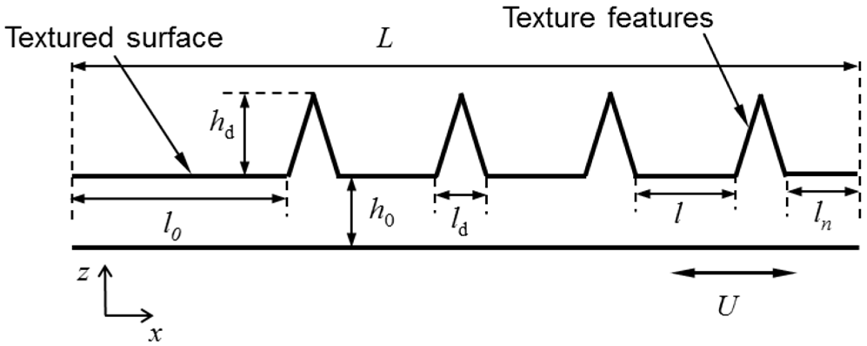
3.2. Textured Slider

Developing an exact analytical model, as in the previous section, for textured bearings with finite width textures is quite tedious due to the requirement for solution of two-dimensional Reynolds equation. Therefore, to evaluate the performance of the textured surface in this study, the analytical relationships given by Rahmani et al. [29] is used, which are primarily for infinite width texture features. Therefore, an approximate solution is obtained, ignoring the effect of ring chamfer profile at the contact inlet conjunction.
As the texture features in this study are triangular in profile, the dimensionless load carrying capacity for asymmetric partially textured surfaces with triangular cross-section is obtained as [29]:
W ¯ = 3 m ε κ ( 1 κ ) ( ξ 1 ) 2 ( m + ε 1 ) ξ 2 m ε κ ( 2 ξ + 1 ) ( ξ 1 )  
In addition, the dimensionless friction becomes [29]:
f ¯ = 4 m ε κ ( ξ 1 ) ( m + ε 1 ) ln ξ + 2 { ( m + ε 1 ) [ ( m + ε 1 ) ξ 2 2 m ε κ ( ξ 2 + 2 ξ 1 ) ] + m 2 ε 2 κ 2 ( ξ + 5 ) ( ξ 1 ) } ( m + ε 1 ) [ 2 ( m + ε 1 ) ξ 2 m ε κ ( 2 ξ 2 ξ 1 ) ]  
where, the height ratio, texture length-to-distance ratio, the leading-edge ratio and the textured portion size are given as:
  ξ = 1 + h d / h 0 ,   ε = l d / l , α 0 = l 0 / L , κ = m l d + ( m 1 ) l  
in which, as is shown in Figure 5, h d and l d are the individual texture feature’s maximum height (or depth) and length (at their base), l 0 is the leading-edge length, l is the edge-to-edge distance between any two consecutive textures and m is the number of textures in the direction of lubricant entrainment. Finally, the scaled coefficient of friction is obtained using Equation (16).
Table 2 lists the values for the parameters used to describe the textured surface utilised in this study.

4. Results and Discussion

Based on the profile of the untextured slider (Figure 1a) and considering Tipei’s inlet boundary conditions [30], λ is approximated as 0.35. Therefore, the associated dimensionless relationships for the load carrying capacity and friction of untextured surface (Equations (12) and (15)) become functions of the chamfer height ratio, ξ , only.
Figure 6 shows the variation of the point of lubricant film rupture (cavitation boundary) with the height ratio parameter for the considered λ value, as well as the variations in the corresponding dimensionless load carrying capacity of the slider (Equations (9) and (12)). Figure 6a shows that the variation in the location of film rupture is rather marginal and occurs just slightly further away from the point where the geometry of the contact becomes divergent. Furthermore, as the slider height ratio increases, the lubricant film rupture point moves further, towards the start of the diverging gap.
Figure 6b shows the dimensionless load carrying capacity, indicating the existence of a specific slider height ratio, where the maximum load carrying capacity is attained. This is approximately at the height ratio of ξ o p t 2.028 with the corresponding maximum dimensionless load carrying capacity of: W ¯ m a x 0.045 , for this specific bearing configuration, where λ = 0.35 .
A comparison of the obtained maximum dimensionless load carrying capacity with those given for the various bearing geometries, including the bearings with textured surfaces in Rahmani and Rahnejat [21], indicates that for the considered bearing design factor of λ = 0.35 , the maximum attainable load carrying capacity is lower than the other studied bearing configurations in [21]. Considering the possible range of variations for λ , it is expected that at lower values of λ , the performance would be closer to a parabolic converging-diverging conjunction.
The corresponding results for generated viscous friction and viscous coefficient of friction are shown in Figure 7. As it can be seen, friction is reduced as the inlet chamfer height ratio increases (Figure 7a). This implies that the minimum film thickness becomes thinner than the chamfer height. However, because the overall gap between the two surfaces increases, the overall friction reduces accordingly.
The scaled coefficient of friction shown in Figure 7b indicates the existence of a minimum value. As the coefficient of friction takes into account the effect of both friction and load carrying capacity and the fact that friction has a monotonic variation with slider height ratio, this minimum value corresponds to the height ratio, where the maximum dimensionless load carrying capacity occurs. It is noted that for the particular bearing configuration, with λ = 0.35 studied here, the minimum value for the scaled coefficient of friction is Ω m i n 20.63 which occurs at ξ o p t 2.10 .
Variations of the geometrical as well as performance parameters for partially textured surfaces have been extensively studied by Rahmani and Rahnejat [21], and thus are not repeated here.
After measuring the generated friction in the textured and untextured sliders with the flat disc using the in-house precision pin-on-disc tribometer, the coefficient of friction was calculated, based on the applied normal load in each case. The results for measured coefficient of friction are given in Figure 8. The coefficient of friction is shown against the Hersey number, which is defined as: H = η U / ( F / B ) , where F is the applied contact load. Therefore, the plot represents a form of Stribeck curve. In addition, the results from the analytical predictions for both untextured and textured surfaces are shown in Figure 8 alongside the corresponding experimental measurements.
The results in Figure 8 show good agreement between the measured and predicted values, for a range of Hersey numbers (representing the in situ regimes of lubrication). In addition, the experimental results for the textured surface show less scatter from the associated trend line for the predicted results. For the untextured surface, the results are slightly scattered. This may be an indication of more stable fluid film formation in the case of the textured surface with perhaps lesser fluctuations caused due to side leakage in the case of textured surface. This aspect requires further investigation.
Figure 8 shows that the textured surface generates reduced friction than its untextured counterpart, particularly at higher Hersey numbers, corresponding to increased dominance of hydrodynamic regime of lubrication. An average reduction in friction coefficient of up to 25%, through use of textured surface is noted. This is quite significant in terms of potential applications for thrust bearings and seals.

5. Conclusions

It is known that the textured surfaces perform better if they are created on flat surfaces [19,20]. On the other hand, the flat surfaces do not provide any load carrying capacity, based on the Reynolds hydrodynamic theory of lubrication. Hence, to benchmark the performance of textured surfaces, a special slider geometry is used in the current study. The slider, in its untextured form, is capable of producing load carrying capacity, due to the existence of a chamfer at its inlet wedge. The same profile also provides a relatively large flat area which allows for the introduction of texture features. Hence, it would be possible to quantify the improvements in friction reduction, using the textured features. In addition, an analytical model is developed to study the untextured slider, which combined with the existing analytical methods in the literature for the textured surfaces provide a unique predictive tool. The predictions, combined with the experimental results, can aid a better fundamental understanding of the physics of flow through textured surfaces, when compared with untextured counterparts.
The analytical methodology developed here is in line with those in References [5,21] which are specifically developed in a manner, based on the geometrical features of the surface. This enables focus on the geometrical parameters for optimisation purposes, as well as providing an insight into the mathematical nature of the relationship between (textured) bearing geometry and the tribological performance.
The analytical predictions and experimental measurements for both untextured and textured profiles are shown to be in a very good agreement. In addition, the textured surface shows a 25% reduction in friction (on average) at various examined operating conditions. This indicates the dominance of the texture geometrical parameters, indicating superior textured surface performance in hydrodynamic regime of lubrication.
An important parameter to consider in any future study is the effect of contact temperature and the potential effect of textured surfaces on heat transfer from tribological contacts.

Author Contributions

Conceptualization, R.R., N.J.M.; methodology, R.R.; validation, N.D.; formal analysis, W.J.T., N.D.; investigation, W.J.T.; resources, R.R., N.J.M., H.R.; data curation, W.J.T., N.D.; writing—original draft preparation, W.J.T., N.D.; writing—review and editing, N.J.M., R.R., H.R.; visualization, N.D.; supervision, N.J.M., R.R., H.R.; project administration, R.R.

Funding

This research received no external funding.

Acknowledgments

The Authors acknowledge the use of facilities in Wolfson School’s Tribodynamics lab.

Conflicts of Interest

The authors declare no conflicts of interest.

Nomenclature

B lateral width of the contact
C 1 , C 2 integration constants
F applied contact load
f friction
f ¯ dimensionless friction
H Hersey number
h contact gap/film thickness
h ¯ dimensionless contact gap
h 0 minimum lubricant film thickness
h c gap at the cavitation inception point
h ¯ c dimensionless gap at cavitation inception point
h d maximum height/depth of texture feature
h i height at the inlet meniscus
L axial length of contact
l edge-to-edge distance between successive textures
l 0 length of untextured leading portion of contact
l d axial length of texture feature at the base
m number of texture features in the direction of entrainment
p hydrodynamic pressure
p ¯ dimensionless pressure
s 1 , s 2 , s 3 , s 4 local height of slider profile at different locations along the entraining direction
s ¯ 1 , s ¯ 2 , s ¯ 3 , s ¯ 4 dimensionless local height of slider profile segments
s i local height of slider at inlet
U sliding speed
W load carrying capacity per unit lateral width
W ¯ dimensionless load carrying capacity per unit lateral width
x axial coordinate along the direction of entraining motion
x ¯ dimensionless distance
x 1 , x 2 , x 3 , x 4 locations where the slider profile changes
x ¯ 1 , x ¯ 2 , x ¯ 3 , x ¯ 4 dimensionless coordinate points
x c cavitation inception point/lubricant film rupture boundary
x ¯ c dimensionless cavitation inception point
z vertical coordinate perpendicular to the entrainment direction
Greek Symbols
ε ratio of texture base length to the edge-to-edge distance between he textures
η dynamic viscosity
κ textured portion
λ ratio of half-length of flat part of slider to the whole length
μ coefficient of friction
ξ slider chamfer or texture height ratio
Ω scaled coefficient of friction
Subscripts
m a x maximum
m i n minimum
o p t optimum
Abbreviations
ACAlternating Current
ASTMAmerican Society for Testing and Materials
CFDComputational Fluid Dynamics
DCDirect Current
DINDeutsches Institut für Normung
EHLElastohydrodynamic lubrication
LSTLaser surface texturing
RMSRoot Mean Square
RPMRevolutions per Minute

References

  1. Etsion, I.; Burstein, L. A model for mechanical seals with regular microsurface structure. Tribol. Trans. 1996, 39, 677–683. [Google Scholar] [CrossRef]
  2. Etsion, I.; Kligerman, Y.; Halperin, G. Analytical and experimental investigation of laser-textured mechanical seal faces. Tribol. Trans. 1999, 42, 511–516. [Google Scholar] [CrossRef]
  3. Burstein, L.; Ingman, D. Pore ensemble statistics in application to lubrication under reciprocating motion. Tribol. Trans. 2000, 43, 205–212. [Google Scholar] [CrossRef]
  4. Ronen, A.; Etsion, I.; Kligerman, Y. Friction-reducing surface-texturing in reciprocating automotive components. Tribol. Trans. 2001, 44, 359–366. [Google Scholar] [CrossRef]
  5. Rahmani, R.; Shirvani, A.; Shirvani, H. Optimised textured surfaces with application in piston ring/cylinder liner contact. In Tribology and Dynamics of Engine and Powertrain; Woodhead Publishing Ltd.: Cambridge, UK, 2010; pp. 470–517. [Google Scholar] [Green Version]
  6. Pettersson, U.; Jacobson, S. Influence of surface texture on boundary lubricated sliding contacts. Tribol. Int. 2003, 36, 857–864. [Google Scholar] [CrossRef]
  7. Zavos, A.; Nikolakopoulos, P.G. The effect of square-shaped pockets position in sliding line contacts under mixed regime of lubrication. Proc. Inst. Mech. Eng. Part J J. Eng. Tribol. 2018. [Google Scholar] [CrossRef]
  8. Krupka, I.; Hartl, M. Effect of surface texturing on very thin film EHD lubricated contacts. Tribol. Trans. 2008, 52, 21–28. [Google Scholar] [CrossRef]
  9. Morris, N.; Leighton, M.; De la Cruz, M.; Rahmani, R.; Rahnejat, H.; Howell-Smith, S. Combined numerical and experimental investigation of the micro-hydrodynamics of chevron-based textured patterns influencing conjunctional friction of sliding contacts. Proc. Inst. Mech. Eng. Part J J. Eng. Tribol. 2015, 229, 316–335. [Google Scholar] [CrossRef] [Green Version]
  10. Morris, N.; Rahmani, R.; Rahnejat, H.; King, P.D.; Howell-Smith, S. A numerical model to study the role of surface textures at top dead center reversal in the piston ring to cylinder liner contact. J. Tribol. 2016, 138, 021703. [Google Scholar] [CrossRef] [Green Version]
  11. Grabon, W.; Pawlus, P.; Wos, S.; Koszela, W.; Wieczorowski, M. Effects of honed cylinder liner surface texture on tribological properties of piston ring-liner assembly in short time tests. Tribol. Int. 2017, 113, 137–148. [Google Scholar] [CrossRef]
  12. Tala-Ighil, N.; Fillon, M.; Maspeyrot, P. Effect of textured area on the performances of a hydrodynamic journal bearing. Tribol. Int. 2011, 44, 211–219. [Google Scholar] [CrossRef]
  13. Morris, N.J.; Rahnejat, H.; Rahmani, R. Tribology of partial pad journal bearings with textured surfaces. In Proceedings of the 3rd European Conference on Tribology (ECOTRIB), Vienna, Austria, 7–9 June 2011. [Google Scholar]
  14. Morris, N.J.; Shahmohamadi, H.; Rahmani, R.; Rahnejat, H.; Garner, C.P. Combined experimental and multiphase computational fluid dynamics analysis of surface textured journal bearings in mixed regime of lubrication. Lubr. Sci. 2018, 30, 161–173. [Google Scholar] [CrossRef] [Green Version]
  15. Lin, Q.; Bao, Q.; Li, K.; Khonsari, M.M.; Zhao, H. An investigation into the transient behavior of journal bearing with surface texture based on fluid-structure interaction approach. Tribol. Int. 2018, 118, 246–255. [Google Scholar] [CrossRef]
  16. Etsion, I. Improving tribological performance of mechanical components by laser surface texturing. Tribol. Lett. 2004, 17, 733–737. [Google Scholar] [CrossRef]
  17. Brizmer, V.; Kligerman, Y.; Etsion, I. A laser surface textured parallel thrust bearing. Tribol. Trans. 2003, 46, 397–403. [Google Scholar] [CrossRef]
  18. Kligerman, Y.; Etsion, I.; Shinkarenko, A. Improving tribological performance of piston rings by partial surface texturing. J. Tribol. 2005, 127, 632–638. [Google Scholar] [CrossRef]
  19. Ryk, G.; Etsion, I. Testing piston rings with partial laser surface texturing for friction reduction. Wear 2006, 261, 792–796. [Google Scholar] [CrossRef]
  20. Rahmani, R. An Investigation into Analysis and Optimisation of Textured Slider Bearings with Application in Piston Ring/Cylinder Liner Contact. Ph.D. Thesis, Anglia Ruskin University, Cambridge, UK, 2008. [Google Scholar]
  21. Rahmani, R.; Rahnejat, H. Enhanced performance of optimised partially textured load bearing surfaces. Tribol. Int. 2018, 117, 272–282. [Google Scholar] [CrossRef]
  22. Gropper, D.; Wang, L.; Harvey, T.J. Hydrodynamic lubrication of textured surfaces: A review of modeling techniques and key findings. Tribol. Int. 2016, 94, 509–529. [Google Scholar] [CrossRef]
  23. ASTM G115-10:2013, Standard Guide for Measuring and Reporting Friction Coefficients; ASTM International: West Conshohocken, PA, USA, 2013.
  24. ASTM G99-05, Standard Test Method for Wear Testing with a Pin-On-Disk Apparatus; ASTM International: West Conshohocken, PA, USA, 2016.
  25. Humphrey, E.; Gkinis, T.; Morris, N.; Leighton, M.; Rahmani, R.; Rahnejat, H. Clutch Lining Frictional Characteristics under Thermal Tribodynamic Conditions. In Proceedings of the 3rd Biennial International Conference on Powertrain Modelling and Control Testing, Mapping and Calibration (PMC 2016), Loughborough, UK, 7–9 September 2016. [Google Scholar]
  26. Gkinis, T.; Rahmani, R.; Rahnejat, H. Effect of Clutch Lining Frictional Characteristics on Take-up Judder. Proc. Inst. Mech. Eng. Part K J. Multi-body Dyn. 2017, 231, 493–503. [Google Scholar] [CrossRef]
  27. Dolatabadi, N.; Rahmani, R.; Theodossiades, S.; Rahnejat, H.; Blundell, G.; Bernard, G. Tribodynamics of Clutch System for Engine-Downsizing in Heavy Duty Off-Highway Vehicles. Proc. Inst. Mech. Eng. Part D J. Automob. Eng. 2018. [Google Scholar] [CrossRef]
  28. Reynolds, O. On the theory of lubrication and its application to Mr. Beauchamp tower’s experiments, including an experimental determination of the viscosity of olive oil. Philos. Trans. R. Soc. Lond. 1886, 177, 157–234. [Google Scholar] [CrossRef]
  29. Rahmani, R.; Mirzaee, I.; Shirvani, A.; Shirvani, H. An analytical approach for analysis and optimisation of slider bearings with infinite width parallel textures. Tribol. Int. 2010, 43, 1551–1565. [Google Scholar] [CrossRef] [Green Version]
  30. Tipei, N. Boundary conditions of a viscous flow between surfaces with rolling and sliding motion. J. Lubr. Technol. 1968, 90, 254–261. [Google Scholar] [CrossRef]
  31. Shahmohamadi, H.; Mohammadpour, M.; Rahmani, R.; Rahnejat, H.; Garner, C.P.; Howell-Smith, S. On the boundary conditions in multi-phase flow through the piston ring-cylinder liner conjunction. Tribol. Int. 2015, 90, 164–174. [Google Scholar] [CrossRef] [Green Version]
  32. Gohar, R. Elastohydrodynamics; Imperial College Press: London, UK, 2001. [Google Scholar]
Figure 1. Profile of: (a) untextured slider and (b) slider used for texturing both measured after polishing using Talysurf CLI-2000 series profilometer.
Lubricants 06 00088 g001
Figure 2. Surface texture analysis (a) White Light Interferometry of equidistant textures on the second slider sample, and (b) indicative texture profile and dimensions.
Lubricants 06 00088 g002
Figure 3. Schematics of the in-house pin-on-disc tribometer utilised for friction measurements.
Lubricants 06 00088 g003
Figure 4. Schematic of the modelled untextured slider profile.
Lubricants 06 00088 g004
Figure 5. Schematics of a textured surface contact and the definition of associated parameters.
Lubricants 06 00088 g005
Figure 6. Variation of the (a) cavitation inception position (film rupture) and (b) dimensionless load carrying capacity with the chamfer height ratio for the untextured slider.
Lubricants 06 00088 g006
Figure 7. Variation of (a) dimensionless friction and (b) scaled coefficient of friction with the height ratio for the untextured slider.
Lubricants 06 00088 g007
Figure 8. Measured and analytically predicted coefficient of friction for textured and untextured sliders.
Lubricants 06 00088 g008
Table 1. Mechanical and surface properties of disc and pin samples.
PropertySymbolPlain SliderTextured SliderDiscUnit
Material_En36CEn36CEn36C_
Modulus of elasticity E 205205205 GPa
Poisson ratio ν 0.300.300.30_
RMS roughness S q 0.330.350.74 μ m
Arithmetic mean roughness S a 0.260.270.57 μ m
Skewness S s k 0.21−0.06−0.21_
Kurtosis S k u 5.454.443.54_
Total maximum height S t 6.785.117.55 μ m
Dimensions_20 × 12 ( L × W ) 20 × 12 ( L × W ) 105 ( ) mm
Table 2. Texture parameters used in the model.
ParameterSymbolValueUnit
Textured portion κ 0.595_
Texture’s length ratio ε 0.75_
No. of textures in axial direction m 10_
Texture maximum depth h d 28.2μm
Leading edge length ratio α 0 0.405_

