Friction of Tungsten-Based Coatings of Steel under Sliding Contact †

Abstract
1. Introduction
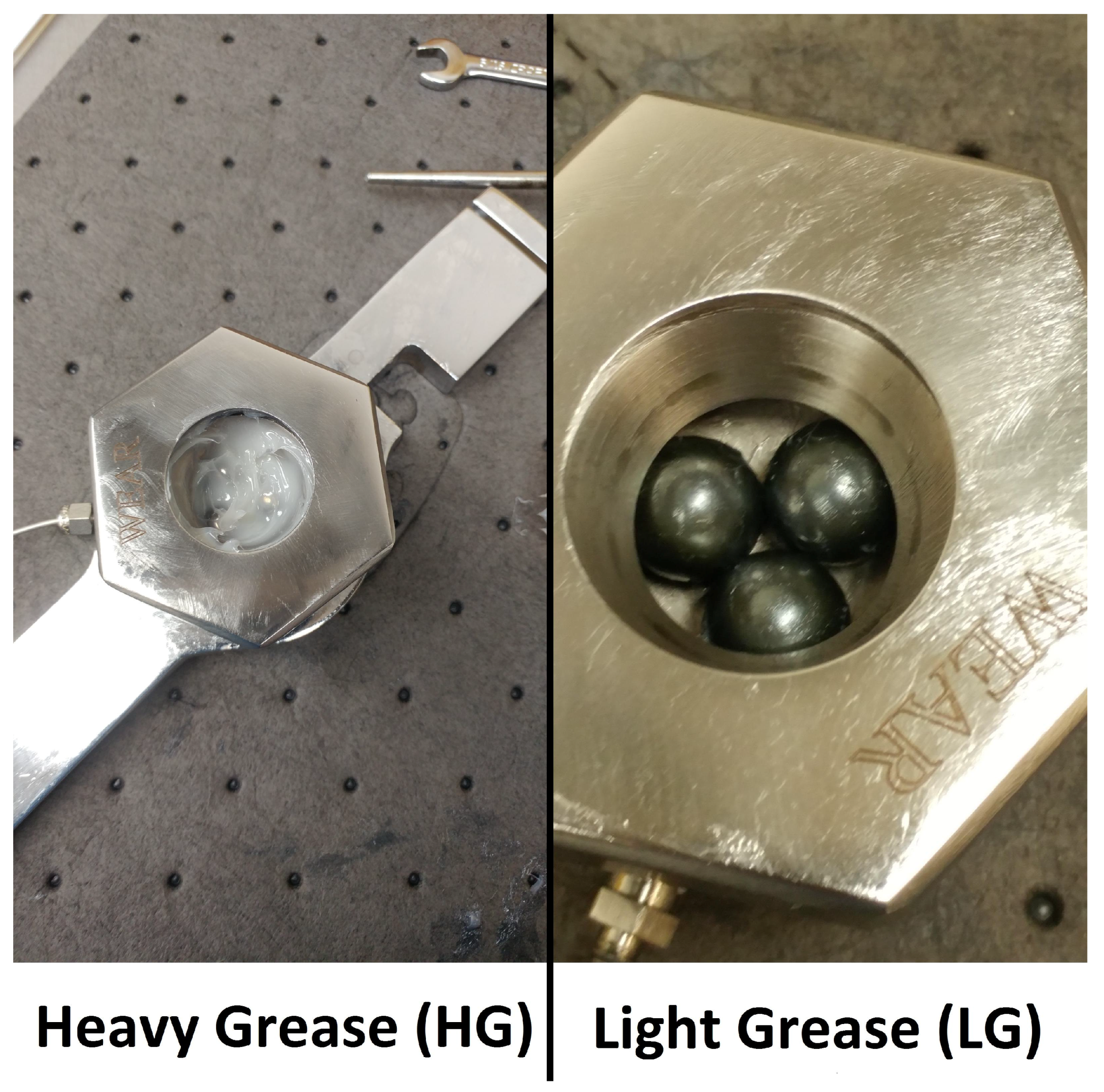
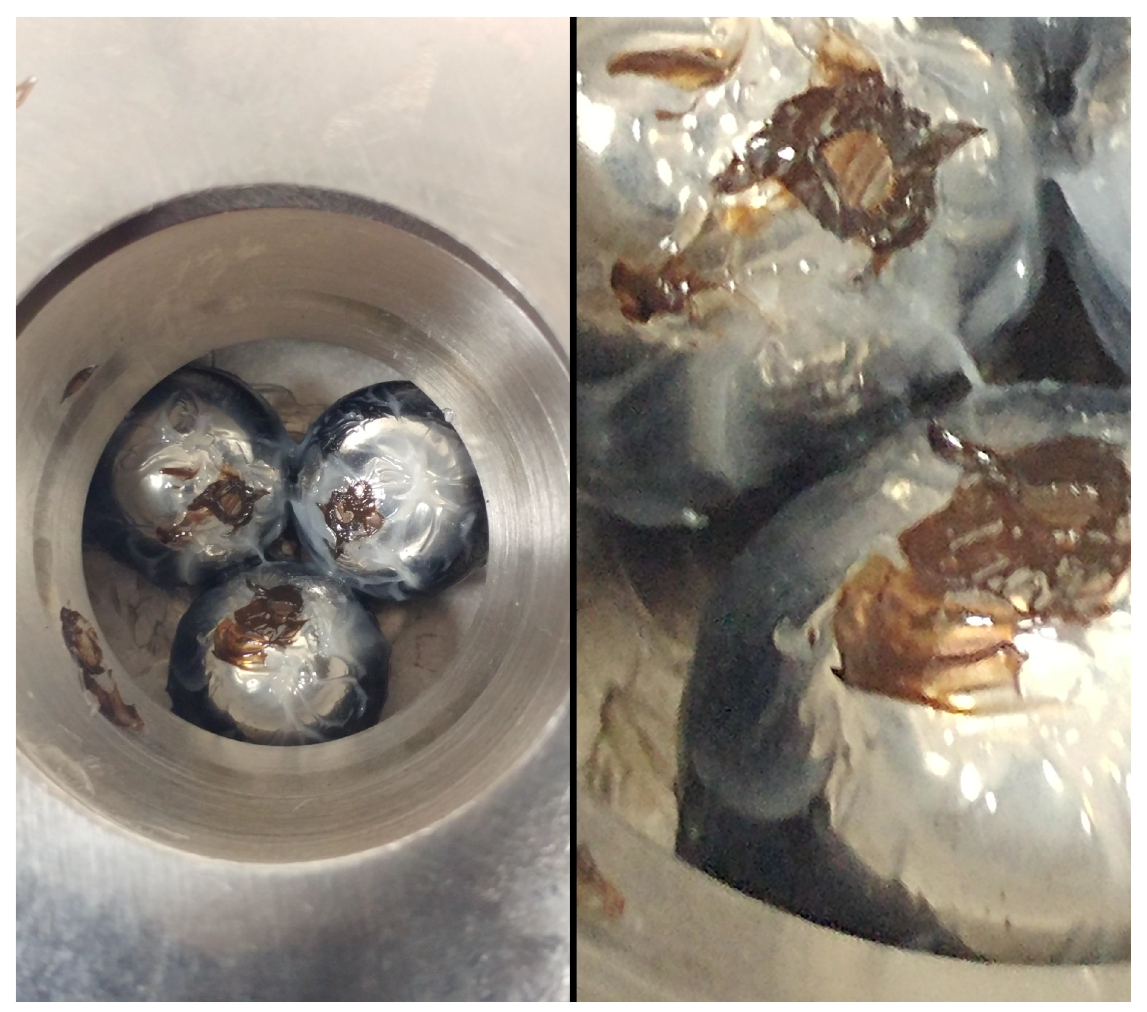
2. Experimental Approach
3. Test Plan
4. Test Results
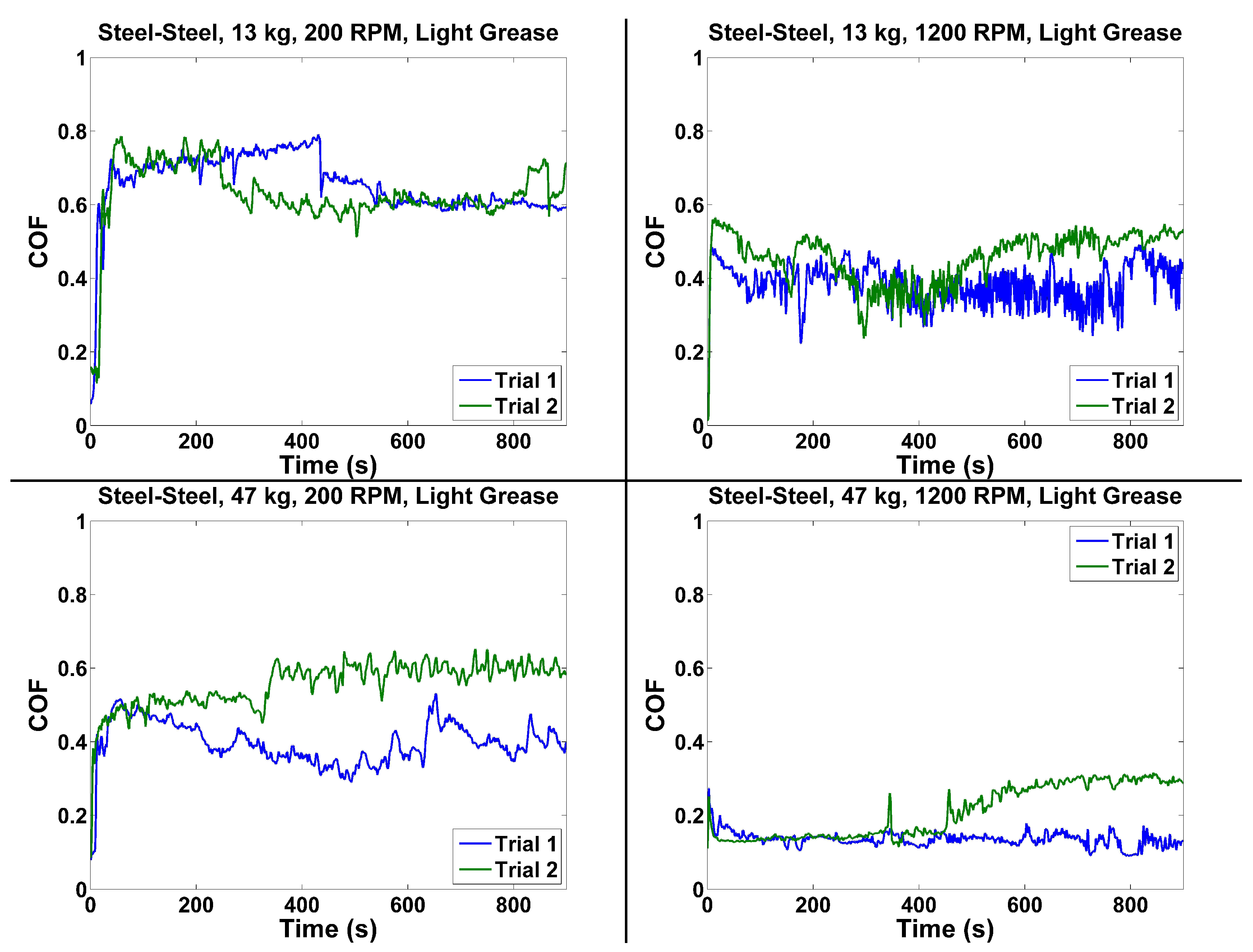
4.1. Steel–Steel
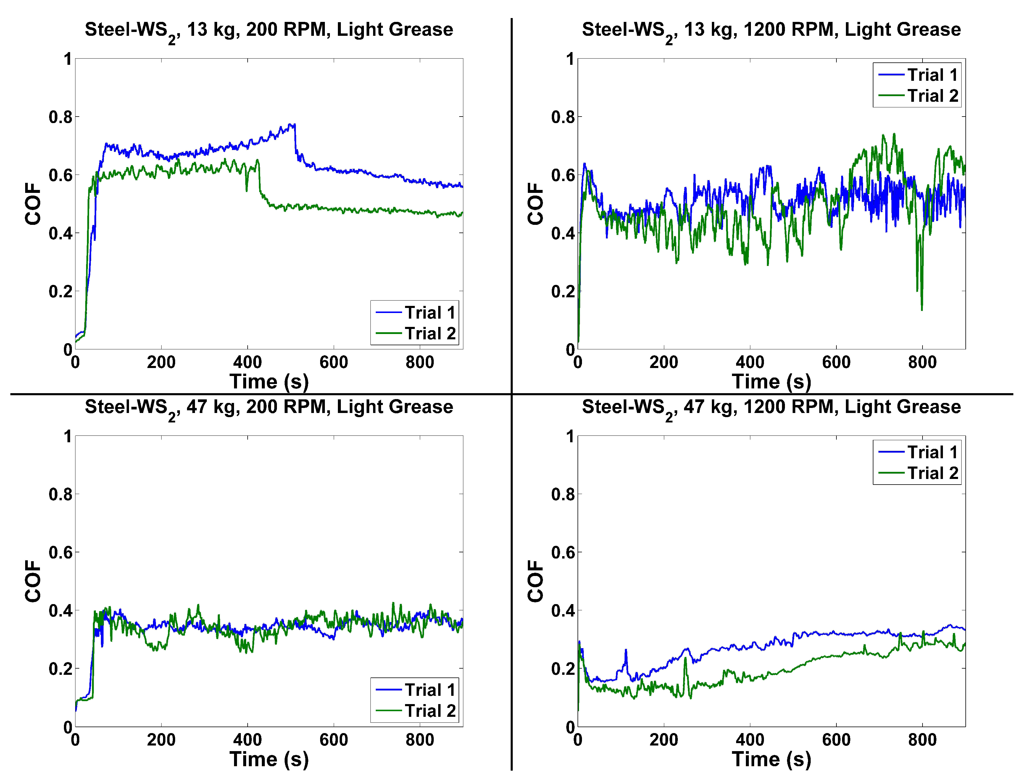
4.2. Steel–
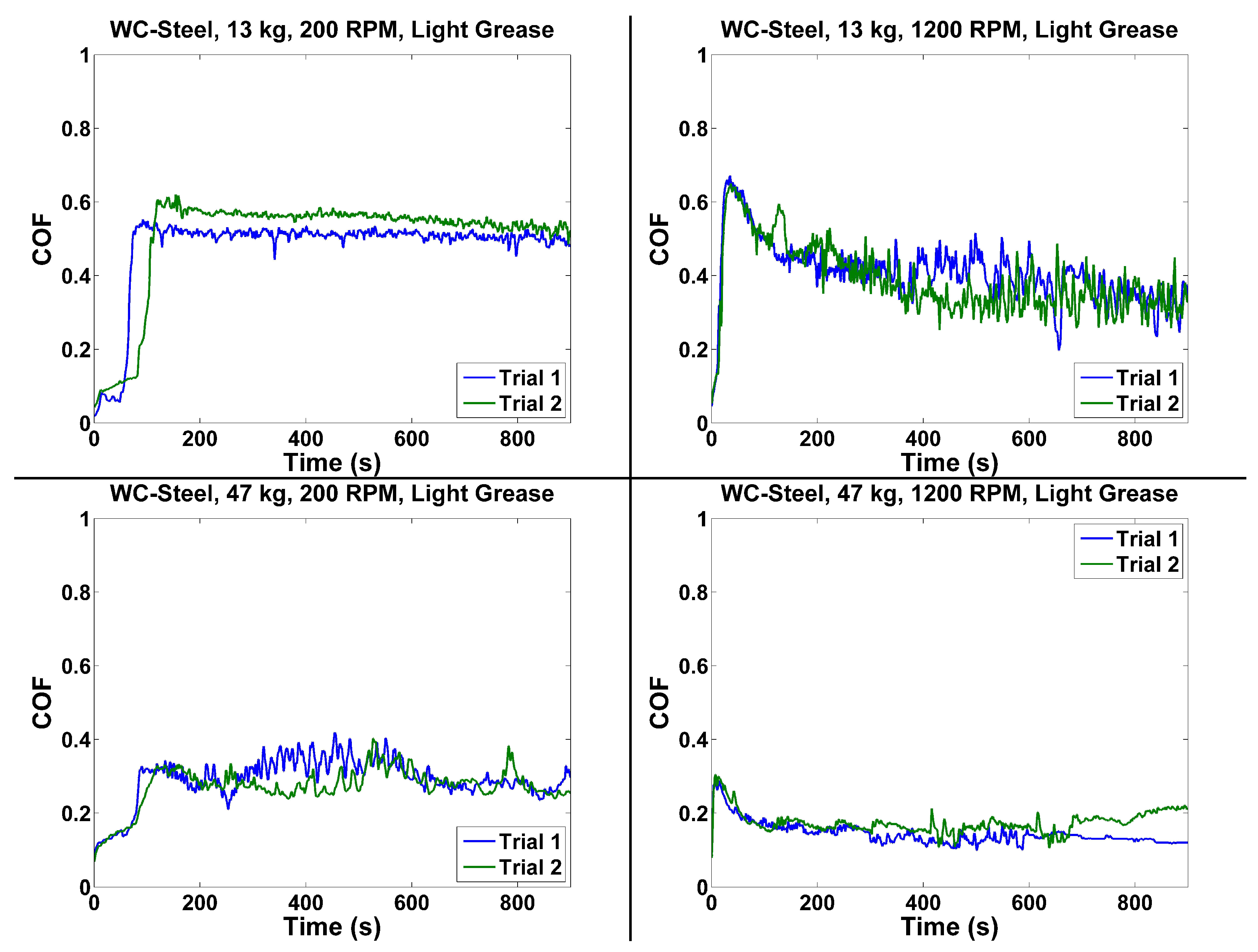
4.3. WC–Steel
4.4. WC–
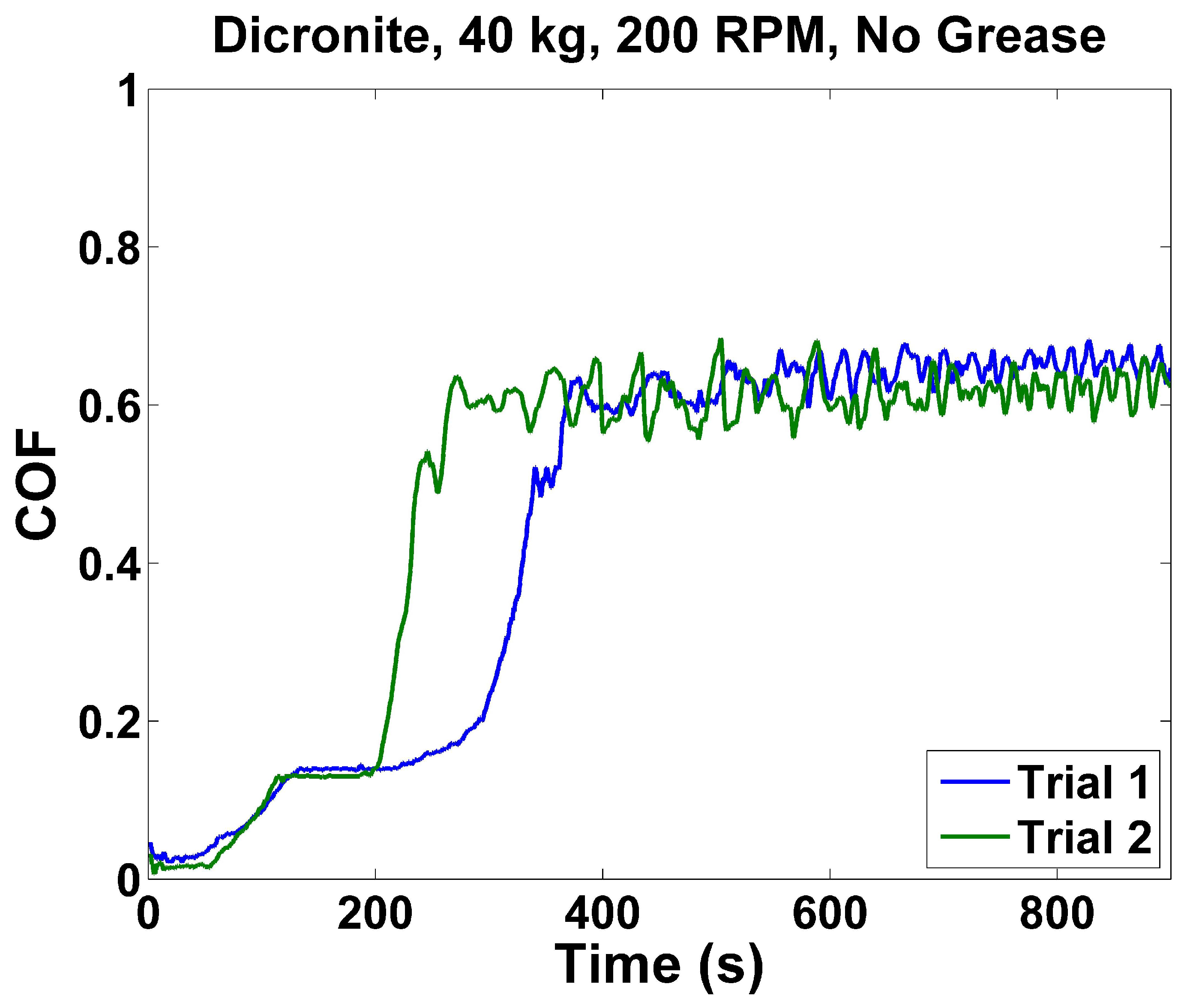
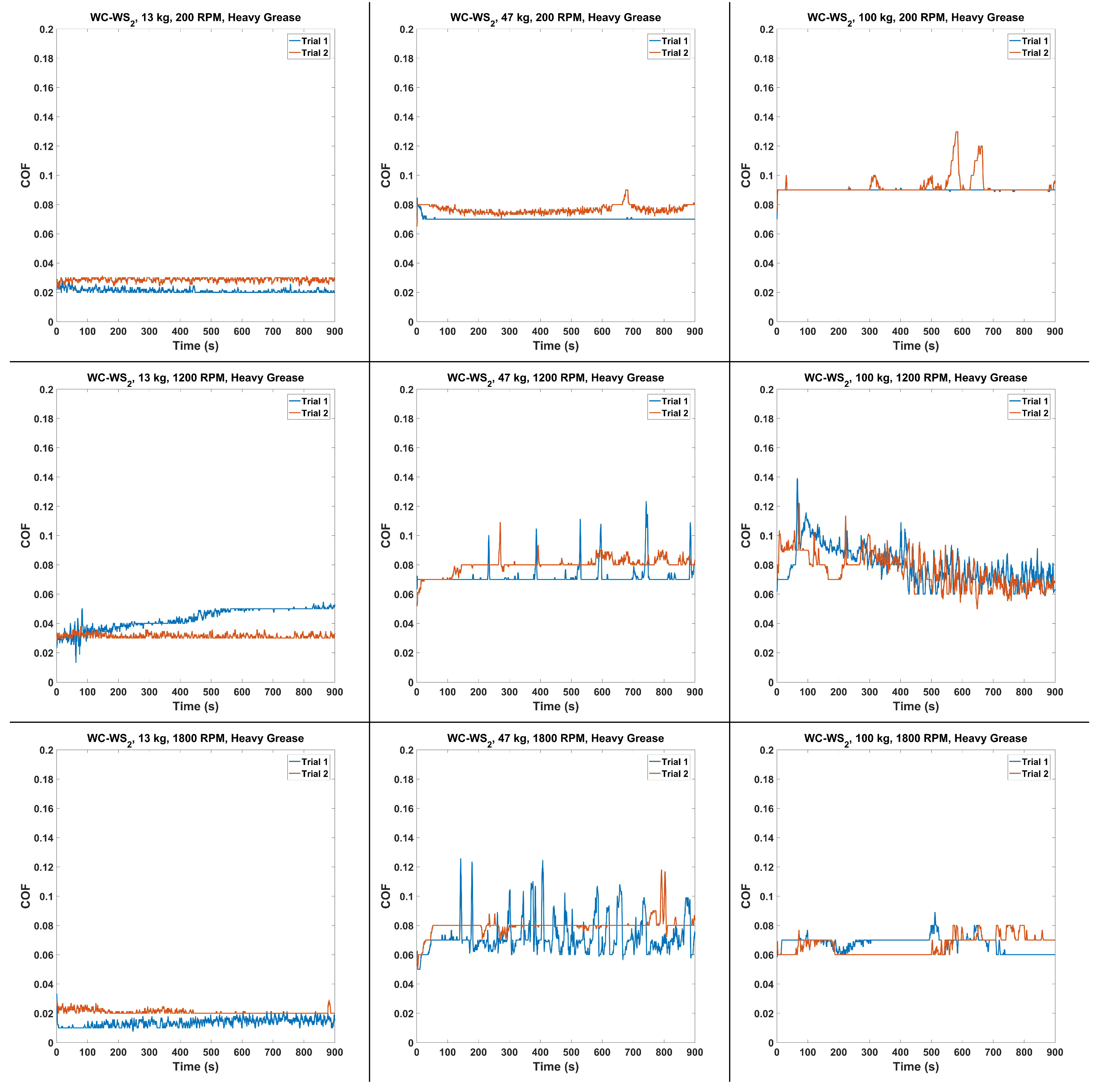
4.5. Heavy Grease WC–
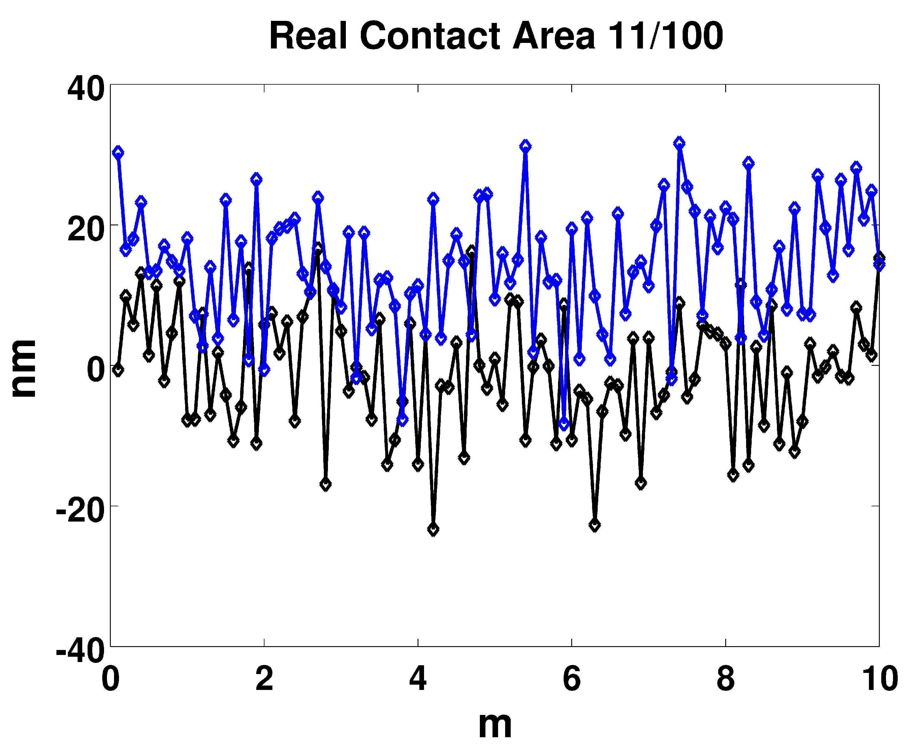
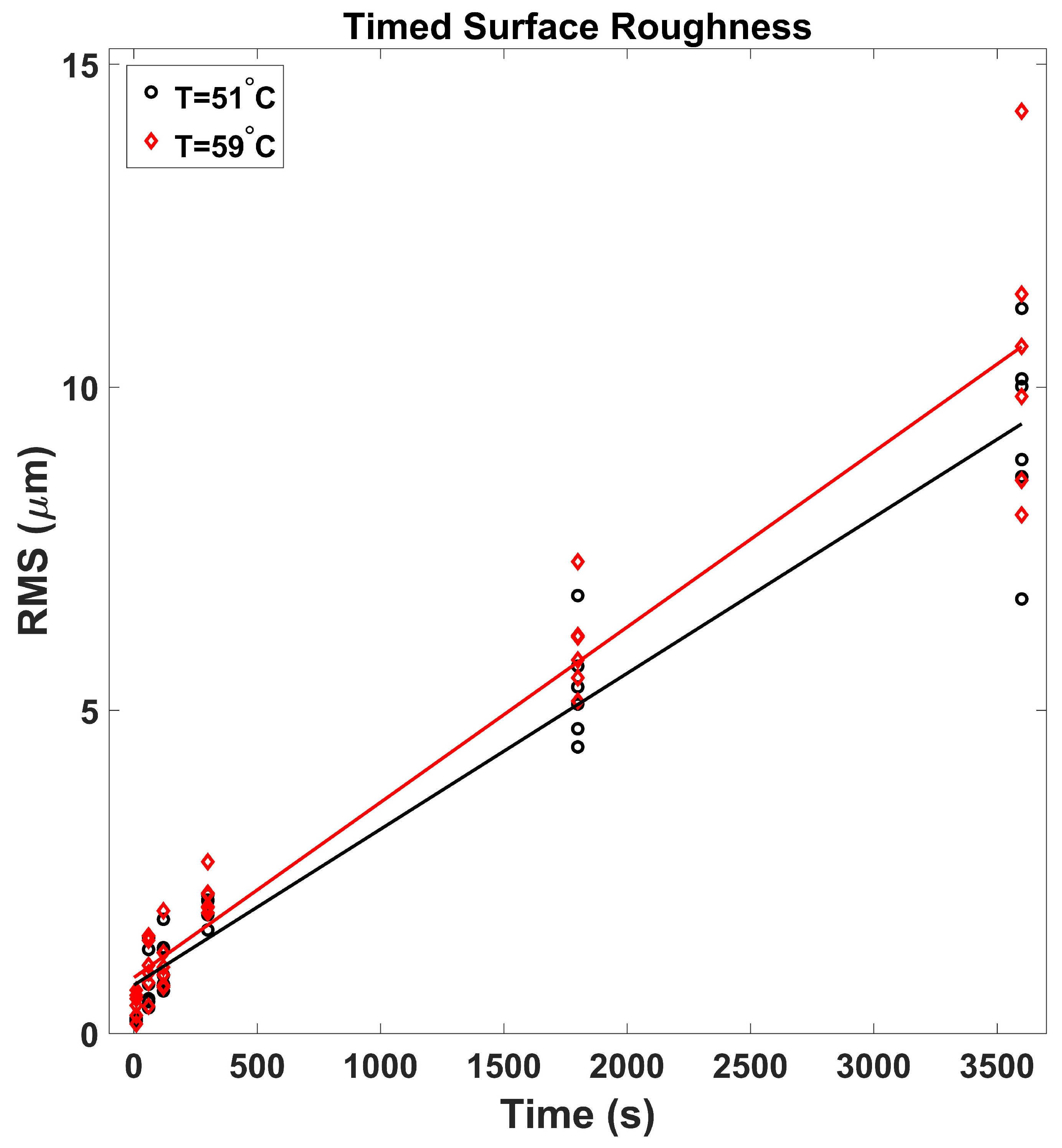
5. Optical Profilometer Measurements
6. Conclusions
Funding
Acknowledgments
Conflicts of Interest
Abbreviations
| COF | Coefficient of Friction |
| HVOF | High Velocity Oxygen Fuel |
| LG | Light-Grease |
| HG | Heavy-Grease |
| ASTM | American Society for Testing and Materials |
| WS | Tungsten Disulfide |
| WC | Tungsten Carbide |
| RMS | Root Mean Square |
| Ra | Roughness Average (Arithmetical Mean Roughness) |
References
- Mudhivarthi, S. Dry Sliding Tribological Characteristics of Hard, Flat Materials with Low Surface Roughness. Master’s Thesis, University of South Florida, Tampa, FL, USA, 2003. [Google Scholar]
- Holmberg, K.; Matthews, A. Coatings Tribology, Properties, Mechanisms, Techniques and Applications in Surface Engineering, 2nd ed.; Elsevier: Amsterdam, The Netherlands, 2009. [Google Scholar]
- Wanstrand, O. Wear Resistant Low Friction Coatings for Machine Elements, Possibilities and Limitations. Ph.D. Thesis, Uppsala University, Uppsala, Sweden, 2000. [Google Scholar]
- Erdemir, A.; Donnet, C. Tribology of diamond-like carbon films: Recent progress and future prospects. J. Phys. D 2006, 39, 311–327. [Google Scholar] [CrossRef]
- Sullivan, J.; Friedmann, T.; Hjort, K. Diamond and amorphous carbon MEMS. Mater. Res. Soc. (MRS) Bull. 2001, 26, 309–311. [Google Scholar] [CrossRef]
- Gupta, B.; Malshe, A.; Bhushan, B.; Subramaniam, V. Friction and wear properties of chemomechanically polished diamond films. J. Tribol. 1994, 116, 445–453. [Google Scholar] [CrossRef]
- Miyoshi, K.; Wu, R.; Garscadden, A.; Barnes, P.; Jackson, H. Friction and wear of plasma deposited diamond films. J. Appl. Phys. 1993, 74, 4446. [Google Scholar] [CrossRef]
- Donnet, C.; Fontaine, J.; Le-Mogne, T.; Belin, M.; Heau, C.; Terrat, J.; Vaux, F.; Pont, G. Diamond-like carbon-based functionally gradient coatings for space tribology. Surf. Coat. Technol. 1999, 120–121, 548–554. [Google Scholar] [CrossRef]
- Scharf, T.; Ohlhausen, J.; Tallant, D.; Prasad, S. Mechanisms of friction in diamond-like nanocomposite coatings. J. Appl. Phys. 2007, 101, 063521-1–063521-11. [Google Scholar] [CrossRef]
- Gardos, M.; Soriano, B. The effect of environment on the tribological properties of polycrystalline diamond films. J. Mater. Res. 1990, 5, 2599–2609. [Google Scholar] [CrossRef]
- Endo, K.; Kotani, S. Observations of Steel Surfaces under Lubricated Wear. Wear 1973, 26, 239–251. [Google Scholar] [CrossRef]
- Nanbu, T.; Yasuda, Y.; Ushijima, K.; Watanabe, J.; Zhu, D. Increase of Traction Coefficient Due to Surface Microtexture. Tribol. Lett. 2008, 29, 105–118. [Google Scholar] [CrossRef]
- Wong, P.; Huang, P.; Wang, W.; Zhang, Z. Effect of geometry change of rough point contact due to lubricated sliding wear on lubrication. Tribol. Lett. 1998, 5, 265–274. [Google Scholar] [CrossRef]
- Saini, B.; Gupta, V.K. Effect of WC/C PVD coating on fatigue behaviour of case carburized SAE8620 steel. Surf. Coat. Technol. 2010, 205, 511–518. [Google Scholar] [CrossRef]
- Abad, M.D.; Munoz-Marquez, M.A.; Mrabet, S.E.; Justo, A.; Sanchez-Lopez, J.C. Tailored synthesis of nanostructured WC/aC coatings by dual magnetron sputtering. Surf. Coat. Technol. 2010, 204, 3490–3500. [Google Scholar] [CrossRef]
- Baragetti, S.; Gerosa, R.; Villa, F. WC/C Coating Protection Effects on 7075-T6 Fatigue Strength in an Aggressive Environment. Procedia Eng. 2014, 74, 33–36. [Google Scholar] [CrossRef]
- Kumar, B.S.; Girish, D. Friction and Wear Behaviour of Tungsten Carbide and E Glass Fibre reinforced Al7075 based Hybrid composites. IOP Publ. Int. Conf. Mater. Manuf. Eng. 2018, 390, 012002. [Google Scholar] [CrossRef]
- Fang, S.; Llanes, L.; Bahre, D. Wear Characterization of Cemented Carbides (WC–CoNi) Processed by Laser Surface Texturing under Abrasive Machining Conditions. Lubricants 2017, 5, 20. [Google Scholar] [CrossRef]
- Fang, S.; Hsu, C.J.; Klein, S.; Llanes, L.; Bahre, D.; Mucklich, F. Influence of Laser Pulse Number on the Ablation of Cemented Tungsten Carbides (WC-CoNi) with Different Grain Size. Lubricants 2018, 6, 11. [Google Scholar] [CrossRef]
- Wu, L.; Guo, X.; Zhang, J. Abrasive Resistant Coatings A Review. Lubricants 2014, 2, 66–89. [Google Scholar] [CrossRef]
- Xu, L.; Song, J.; Zhang, X.; Deng, C.; Liu, M.; Zhou, K. Microstructure and Corrosion Resistance of WC-Based Cermet/Fe-Based Amorphous Alloy Composite Coatings. Coatings 2018, 8, 393. [Google Scholar] [CrossRef]
- Tillmann, W.; Hagen, L.; Luo, W. Process Parameter Settings and Their Effect on Residual Stresses in WC/W2 C Reinforced Iron-Based Arc Sprayed Coatings. Coatings 2017, 7, 125. [Google Scholar] [CrossRef]
- Humphry-Baker, S.; Marshall, J. Structure and Properties of High-Hardness Silicide Coatings on Cemented Carbides for High Temperature Applications. Coatings 2018, 8, 247. [Google Scholar] [CrossRef]
- AMS B Finishes Processes and Fluids Committee. Application of Tungsten Carbide Coatings on Ultra High Strength Steels High Velocity Oxygen/Fuel Process. AMS 2448B; Society of Automotive Engineering (SAE) International: Warrendale, PA, USA, 2004. [Google Scholar]
- Stachowiak, G.; Batchelor, A. Engineering Tribology, 4th ed.; Butterworth-Heinemann: Oxford, UK, 2005. [Google Scholar]
- Hu, Y.; Li, N.; Tønder, K. A Dynamic System Model for Lubricated Sliding Wear and Running-in. J. Tribol. 1991, 113, 499–505. [Google Scholar] [CrossRef]
- Johnson, K. Contact Mechanics; Cambridge University Press: New York, NY, USA, 1987. [Google Scholar]
- Gohar, R. Elastohydrodynamics; World Scientific Publishing Company: Singapore, 2002. [Google Scholar]
- Engineering ToolBox. Friction and Friction Coefficients. 2004. Available online: https://www.engineeringtoolbox.com/friction-coefficients-d_778.html (accessed on 16 August 2018).
- Xu, S.; Gao, X.; Hu, M.; Sun, J.; Jiang, D.; Wang, D.; Zhou, F.; Weng, L.; Liu, W. Dependence of atomic oxygen resistance and the tribological properties on microstructures of WS2 films. Appl. Surf. Sci. 2014, 298, 36–43. [Google Scholar] [CrossRef]
- Xu, S.; Gao, X.; Sun, J.; Hu, M.; Wang, D.; Jiang, D.; Zhou, F.; Weng, L.; Liu, W. Comparative study of moisture corrosion to WS2 and WS2/Cu multilayer films. Surf. Coat. Technol. 2014, 247, 30–38. [Google Scholar] [CrossRef]
- Quan, X.; Hu, M.; Gao, X.; Fu, Y.; Weng, L.; Wang, D.; Jiang, D.; Sun, J. Friction and wear performance of dual lubrication systems combining WS2-MoS2 composite film and low volatility oils under vacuum condition. Tribol. Int. 2016, 99, 57–66. [Google Scholar] [CrossRef]
- Quan, X.; Zhang, S.; Hu, M.; Gao, X.; Jiang, D.; Sun, J. Tribological properties of WS2/MoS2-Ag composite films lubricated with ionic liquids under vacuum conditions. Tribol. Int. 2017, 115, 389–396. [Google Scholar] [CrossRef]
- Maharaj, D.; Bhushan, B. Effect of Mo2 and WS2 Nanotubes on Nanofriction and Wear Reduction in Dry and Liquid Environments. Tribol. Lett. 2013, 49, 323–339. [Google Scholar] [CrossRef]
- Di, Y.; Cai, Z.; Zhang, P. The Tribological Performance of CrMoN/MoS2 Solid Lubrication Coating on a Piston Ring. Lubricants 2017, 5, 13. [Google Scholar] [CrossRef]
- Cann, P.; Spikes, H. In-contact IR spectroscopy of hydrocarbon lubricants. Tribol. Lett. 2005, 19, 289–297. [Google Scholar] [CrossRef]
- Jiang, P.; Li, X.M.; Guo, F.; Chen, J. Interferometry Measurement of Spin Effect on Sliding EHL. Tribol. Lett. 2009, 33, 161–168. [Google Scholar] [CrossRef]
- Reddyhoff, T.; Spikes, H.A.; Olver, A.V. Compression Heating and Cooling in Elastohydrodynamic Contacts. Tribol. Lett. 2009, 36, 69–80. [Google Scholar] [CrossRef]
- Hamrock, B.; Dowson, D. Isothermal Elastohydrodynamic Lubrication of Point Contacts, III Fully Flooded Results. D-8317; Technical Report; NASA: Washington, DC, USA, 1976.
- Ranger, A.; Ettles, C.; Cameron, A. The Solution of the Point Contact Elasto-Hydrodynamic Problem. Proc. R. Soc. Lond. Ser. A Math. Phys. Sci. 1975, 346, 227–244. [Google Scholar] [CrossRef]
- Fillot, N.; Berro, H.; Vergne, P. From Continuous to Molecular Scale in Modelling Elastohydrodynamic Lubrication: Nanoscale Surface Slip Effects on Film Thickness and Friction. Tribol. Lett. 2011, 43, 257–266. [Google Scholar] [CrossRef]
- Guo, F.; Wong, P.L.; Geng, M.; Kaneta, M. Occurrence of Wall Slip in Elastohydrodynamic Lubrication Contacts. Tribol. Lett. 2009, 34, 103–111. [Google Scholar] [CrossRef]
- Krupka, I.; Bair, S.; Kumar, P.; Svoboda, P.; Hartl, M. Mechanical Degradation of the Liquid in an Operating EHL Contact. Tribol. Lett. 2011, 41, 191–197. [Google Scholar] [CrossRef]
- Automotive Lubricating Greases. Available online: https://www.sae.org/standards/content/j310_199004/ (accessed on 16 August 2018).
- Standard Test Method for Wear Preventive Characteristics of Lubricating Fluid (Four-Ball Method). ASTM Int. 2016. [CrossRef]
- Standard Test Method for Measurement of Extreme-Pressure Properties of Lubricating Fluids (Four-Ball Method). ASTM Int. 2014. [CrossRef]
- Marko, M.D.; Kyle, J.P.; Branson, B.; Terrell, E.J. Tribological Improvements of Dispersed Nano-Diamond Additives in Lubricating Mineral Oil. J. Tribol. 2015, 137, 011802. [Google Scholar] [CrossRef]
- Marko, M.D.; Kyle, J.P.; Wang, Y.S.; Branson, B.; Terrell, E.J. Numerical and Experimental Tribological Investigations of Diamond Nanoparticles. J. Tribol. 2016, 138, 032001. [Google Scholar] [CrossRef]
- Marko, M.; Kyle, J.P.; Wang, Y.S.; Terrell, E.J. Tribological investigations of the load, temperature, and time dependence of wear in sliding contact. PLoS ONE 2017, 12. [Google Scholar] [CrossRef]
- Spanu, C.; Ripa, M.; Ciortan, S. Study of Wear Evolution for a Hydraulic Oil Using a Four-Ball Tester. Ann. Univ. Dunareade Jos Galati 2008, 8, 186–189. [Google Scholar]
- DOD-L-85645A. Inclined Plane Test Specification: Lubricant, Dry Thin Film, Molecular Bonded. Available online: http://everyspec.com/DoD/DoD-SPECS/DOD-L-85645A_5698/ (accessed on 16 August 2018).
- Hamrock, B.; Dowson, D. Isothermal Elastohydrodynamic Lubrication of Point Contacts, I Theoretical Formulation. D-8049; Technical Report; NASA: Washington, DC, USA, 1975.
- Hamrock, B.; Dowson, D. Isothermal Elastohydrodynamic Lubrication of Point Contacts, IV Starvation Results. D-8318; Technical Report; NASA: Washington, DC, USA, 1976.
- Dowson, D. Elastohydrodynamic and micro-elastohydrodynamic lubrication. Wear 1995, 190, 125–138. [Google Scholar] [CrossRef]
- Cameron, A.; Gohar, R. Theoretical and Experimental Studies of the Oil Film in Lubricated Point Contact. Proc. R. Soc. Lond. Ser. A Math. Phys. Sci. 1966, 291, 520–536. [Google Scholar] [CrossRef]
- Archard, J. Contact and Rubbing of Flat Surfaces. J. Appl. Phys. 1953, 24, 981–988. [Google Scholar] [CrossRef]
- Greenwood, J.; Williamson, J. Contact of Nominally Flat Surfaces. Proc. R. Soc. Lond. A 1966, 295, 300–319. [Google Scholar] [CrossRef]
- Bush, A.; Gibson, R.; Keogh, G. The Limit of Elastic Deformation in the Contact of Rough Surfaces. Mech. Res. Commun. 1976, 3, 169–174. [Google Scholar] [CrossRef]
- Carbone, G. A slightly corrected Greenwood and Williamson model predicts asymptotic linearity between contact area and load. J. Mech. Phys. Solids 2009, 57, 1093–1102. [Google Scholar] [CrossRef]
- McCool, J. Comparison of Models for the Contact of Rough Surfaces. Wear 1986, 107, 37–60. [Google Scholar] [CrossRef]
- Bush, A.; Gibson, R.; Thomas, T. The Elastic Contact of a Rough Surface. Wear 1975, 35, 87–111. [Google Scholar] [CrossRef]
- Persson, B. Contact mechanics for randomly rough surfaces. Surf. Sci. Rep. 2006, 61, 201–227. [Google Scholar] [CrossRef]
- Golden, J. The Evolution of Asperity Height Distributions of a Surface Seeoed to Wear. Wear 1976, 39, 25–44. [Google Scholar] [CrossRef]
- Bayer, R.; Sirico, J. The Influence of Surface Roughness on Wear. Wear 1975, 35, 251–260. [Google Scholar] [CrossRef]
- Shafia, M.; Eyre, T. The Effect of Surface Topography on the Wear of Steel. Wear 1980, 61, 87–100. [Google Scholar] [CrossRef]
- Marko, M. The Tribological Effects of Lubricating Oil Containing Nanometer-Scale Diamond Particles. Ph.D. Thesis, Columbia University, New York, NY, USA, 2015. [Google Scholar] [CrossRef]
- Blau, P. On the nature of running-in. Tribol. Int. 2005, 38, 1007–1012. [Google Scholar] [CrossRef]


| Grease | Material | Load (N) | Speed (r/min) | COF | COF (900 s) | Scar (mm) |
|---|---|---|---|---|---|---|
| LG | Steel–Steel | 128 | 200 | 0.5787 | 0.65125 | 1.0563 |
| LG | Steel–Steel | 461 | 200 | 0.3212 | 0.4802 | 0.8293 |
| LG | Steel–Steel | 128 | 1200 | 0.3307 | 0.42015 | 1.6949 |
| LG | Steel–Steel | 461 | 1200 | 0.1091 | 0.17155 | 0.9847 |
| Grease | Material | Load (N) | Speed (r/min) | COF | COF (900 s) | Scar (mm) |
|---|---|---|---|---|---|---|
| LG | Steel– | 128 | 200 | 0.4251 | 0.5832 | 1.0499 |
| LG | Steel– | 461 | 200 | 0.248 | 0.339 | 0.8184 |
| LG | Steel– | 128 | 1200 | 0.3068 | 0.50195 | 1.3511 |
| LG | Steel– | 461 | 1200 | 0.1170 | 0.23415 | 1.2672 |
| Grease | Material | Load (N) | Speed (r/min) | COF | COF (300–900 s) | COF (900 s) | Scar (mm) |
|---|---|---|---|---|---|---|---|
| LG | WC-Steel | 128 | 200 | 0.1052 | 0.4950 | 0.4997 | 0.7089 |
| LG | WC-Steel | 461 | 200 | 0.1427 | 0.2532 | 0.2843 | 0.838 |
| LG | WC-Steel | 128 | 1200 | 0.3166 | 0.3166 | 0.40205 | 1.186 |
| LG | WC-Steel | 461 | 1200 | 0.1176 | 0.1176 | 0.15785 | 1.1885 |
| Grease | Material | Load (N) | Speed (r/min) | COF | COF (300–900 s) | COF (900 s) | Scar (mm) |
|---|---|---|---|---|---|---|---|
| LG | WC– | 128 | 200 | 0.0883 | 0.4075 | 0.47085 | 0.75742 |
| LG | WC– | 128 | 1200 | 0.2189 | 0.2189 | 0.37805 | 0.74092 |
| LG | WC– | 461 | 200 | 0.1355 | 0.2218 | 0.23365 | 1.21125 |
| LG | WC– | 461 | 1200 | 0.1149 | 0.1149 | 0.16895 | 1.4375 |
| LG | WC– | 981 | 200 | 0.1983 | 0.1983 | 0.2429 | 1.0042 |
| LG | WC– | 981 | 1800 | 0.0415 | 0.0415 | 0.0859 | 1.12225 |
| Grease | Material | Load (N) | Speed (r/min) | COF | COF (900 s) | Scar (mm) |
|---|---|---|---|---|---|---|
| HG | WC– | 128 | 200 | 0.0201 | 0.02485 | 0.26533 |
| HG | WC– | 128 | 1200 | 0.0301 | 0.0375 | 0.2535 |
| HG | WC– | 128 | 1800 | 0.0101 | 0.0172 | 0.3005 |
| HG | WC– | 461 | 200 | 0.0700 | 0.07325 | 0.419 |
| HG | WC– | 461 | 1200 | 0.0692 | 0.0758 | 0.56125 |
| HG | WC– | 461 | 1800 | 0.0652 | 0.0762 | 0.67375 |
| HG | WC– | 981 | 200 | 0.0899 | 0.06685 | 0.461083 |
| HG | WC– | 981 | 1200 | 0.0646 | 0.09125 | 1.0535 |
| HG | WC– | 981 | 1800 | 0.0600 | 0.07795 | 0.651 |
© 2019 by the author. Licensee MDPI, Basel, Switzerland. This article is an open access article distributed under the terms and conditions of the Creative Commons Attribution (CC BY) license (http://creativecommons.org/licenses/by/4.0/).
Share and Cite
Marko, M.D. Friction of Tungsten-Based Coatings of Steel under Sliding Contact. Lubricants 2019, 7, 14. https://doi.org/10.3390/lubricants7020014
Marko MD. Friction of Tungsten-Based Coatings of Steel under Sliding Contact. Lubricants. 2019; 7(2):14. https://doi.org/10.3390/lubricants7020014
Chicago/Turabian StyleMarko, Matthew David. 2019. "Friction of Tungsten-Based Coatings of Steel under Sliding Contact" Lubricants 7, no. 2: 14. https://doi.org/10.3390/lubricants7020014
APA StyleMarko, M. D. (2019). Friction of Tungsten-Based Coatings of Steel under Sliding Contact. Lubricants, 7(2), 14. https://doi.org/10.3390/lubricants7020014