The Activation and Evolution of Twinning during Bending of Friction Stir Welded AZ31 Magnesium Alloys


School of Material Science and Engineering, Taiyuan University of Science and Technology, Taiyuan 030024, China
*
Author to whom correspondence should be addressed.
Metals 2020, 10(1), 139; https://doi.org/10.3390/met10010139
Submission received: 7 December 2019
/
Revised: 9 January 2020
/
Accepted: 14 January 2020
/
Published: 16 January 2020
Abstract
:AZ31 magnesium alloy joints obtained by friction stir welding with rotation speed of 1400 rpm and welding speed of 200 mm/min were subsequently subjected to the three-point bending process. The bending behavior, microstructure evolution and twinning mechanism were investigated. The results indicate that the stress-strain curve appeared as power-law shape during tension and the stress-strain curve appeared as work hardening shape during compression. However, the stress-strain curve during bending is different and macrographs of face and base bending indicated that the severe strain localization was present during bending of FSWed AZ31 magnesium alloy joint. Three concave regions formed due to texture distribution and stress state in the weld zone. In those regions, the grains had favorable orientation with c-axis parallel to the direction of tensile stress and abundant twins were activated. It can be proved by electron backscatter diffraction (EBSD) analysis—two twinning mechanisms were activated during bending—that is, ~56° {} contraction twin and ~86° {} expansion twin, in which {} twinning was main plastic deformation mechanism of joint and the number of twins was proportional to the compressive stress in corresponding areas. The twinning resulted in lattice rotation about 86° around <> direction and changed the orientation distribution of original crystal.
1. Introduction
Magnesium (Mg) alloys have high strength-to-weight ratio and low density, which has attracted increasing interest in many fields, such as transportation and electronic industries [1,2]. However, for hexagonal-close-packed (hcp) Mg alloys, only two independent basal slip systems and twinning systems can be activated during deformation at room temperature. This does not fit the von Mises criterion with five independent systems and Mg alloys exhibit poor ductility [3,4]. Friction stir welding (FSW) is a solid-state joining technology and is successfully used in Mg alloys, which can refine grain [5], compensate for low formability and expand their application as structural materials [6,7,8]. However, strong deformation texture and mixed crystal are usually formed in welded zones, which induce different degree rotation and lattice distortion during deformation [9,10,11]. Therefore, microstructure in the welded zone complicates the deformation behavior and leads to severe strain localization. Hence, it is important to illuminate the texture evolution and deformation coordination mechanism of FSWed Mg alloys joint with complicated texture.
It is well known that {} <> extension twinning and {} <)> contraction twinning are two important deformation mechanisms for hcp Mg alloys at room temperature [12,13]. The activity of extension twinning and contraction twinning are related to grain orientation and loading condition, as well as c/a ratio (γ) of Mg alloys [13,14]. It has been widely reported that the {} <> system is the most commonly twinning mode in all hcp metals [15,16,17]. But, twinning is unidirectional since the twinning shear is uniquely defined by the second invariant plane, that is, the K2 plane and the twinning direction η1 [18]. The {} <> twinning is most favorable when a tensile stress is parallel to the c-axis of the Mg crystal. On the contrary, it is suppressed when a compressive stress is parallel to the c-axis or a tensile stress is perpendicular to the c-axis [13]. Therefore, the twinning mechanism may be complicated under different stress condition of FSWed Mg alloy joint with different texture distribution. The bending process as a widely used forming technique is indispensable in the forming of Mg alloys [19]. In addition, the stress and strain condition during bending is also different between the inner and outer surfaces, that is, the outer region is under tension while the inner region is under compression, which may also lead to largely different twinning behavior. Huang et al. indicated that the length of the AZ31 Mg alloy sheet was shortened during bending for the neutral axis moving slightly toward the tension region, which is due to the tension-compression asymmetry between the outer and inner regions [20]. For the previous studies, only the sheets with basal texture were used for investigating the microstructure and twinning evolution during the bending process, while the effects of different initial texture in FSWed joint on the bending behavior were out of consideration. Therefore, it is necessary to investigate the effect of different textures on the twinning activation and texture evolution during the bending process.
The objective of this study is to clarify the activation condition and evolution mechanism of twinning during two types of bending tests of FSWed Mg alloy joints. A surface bending test and base bending test with different strains for FSWed AZ31 Mg alloy joints were conducted. The twin characteristics and evolution process in the tension zone and the compressive zone were specifically analyzed using optical microscopy (OM) and electron-backscatter diffraction (EBSD).
2. Materials and Experimental Procedures
A die-casting AZ31 Mg alloy (Mg-3%Al-1%Zn) with the thickness of 6 mm was used as the base material (BM) in this study. The microstructure consists of coarse elongated grains and a few fine equiaxed grains without twins, as shown in Figure 1. After mechanically grinding with abrasive paper and cleaning with acetone, AZ31 Mg alloys successfully welded along rolling direction (RD) at the rotation rate of 1400 rpm and the welding speed of 200 mm/min. A cylindrical stir tool with thread pin (φ5 mm × 5.7 mm) was used. The welded samples were sectioned perpendicular to welding direction (WD) for microstructure observation.
Microstructure examination was conducted by light microscopy and EBSD. The light microscopy samples were grinded using SiC abrasive papers and polished using diamond abrasive pastes. Those prepared samples were etched using a solution comprising 10 mL acetic acid (99%), 10 mL distilled water, 4.2 g picric acid and 100 mL ethanol (95%). The EBSD samples were electrolytic polished using a commercial polishing solution (AC2) at 38 V and room temperature. The EBSD testing was performed on a ZEISS ULTRA 55 (Carl Zeiss AG, Oberkochen, Germany) field-emission scanning electron microscopy with a step size of 1.0 μm. The HKL Channel 5 (Oxford Instruments, London, UK) software was used to analyze the EBSD scan data.
Rectangular shaped samples with dimensions of 100 mm (transverse direction, TD) × 10 mm (welding direction, WD) × 5 mm (normal direction, ND) were machined for three point bending. Two kinds of deformation geometry, that is, Surface bending test (load applied on surface of FSWed joint) and Base bending test (load applied on base of FSWed joint), were used for bending tests, as shown in Figure 2a. The beam span for the bending tests was 55 mm and the movement speed of pressure head was set to 2 mm/min. The bending tests were performed at room temperature using a hydraulic universal testing machine (SUNS-UTM5305, Suns, Shenzhen, China) and interrupted at stain of 5% and 8% of outer surface to examine twinning and microstructure evolution.
3. Results and Discussion
3.1. Original Microstructure of FSWed AZ31 Mg Alloy Joint
The AZ31 Mg alloys were friction stir welded with rotation speed of 1400 rpm and welding speed of 200 mm/min and the whole morphology and microstructure characteristics in different zones were shown in Figure 3. It indicates that the grains in stir zone (SZ) were significantly refined after FSW, as shown in Figure 3a. Meanwhile, obvious interface formed between SZ and base material, in which no defects were observed. To examine microstructure evolution and texture distribution, different positions in SZ were chosen for EBSD analysis, as indicated in Figure 3b–d and Figure 4. Figure 3c shows that position 2, that is, the central area, possessed minimum grain size and the average grain size was measured to be ~7.0 μm. Then, the average grain sizes were 8.4 μm and 9.2 μm in position 1 and position 3, respectively. The significant grain refinement was obtained by dynamic recrystallization with the help of frictional heating and plastic deformation during FSW process [21,22].
In addition, inverse pole figure (IPF) maps with different color in different zones, which indicates that grains in SZ rotated at varying degrees during FSW process. As shown in Figure 4, the {} and {} pole figures in different areas distribute nearly at random. On the contrary, the strong basal texture was formed after FSW and position 2 possessed the strongest (0001) basal texture with the c-axis parallel to WD and the intensity was 56.36. However, the grains rotated from WD to TD in position 1 and position 3 in SZ-side and the intensities reduced in some degree and were measured to be 42.09 and 38.76, respectively. According to previous studies, the grains with different orientation show well the different deformation behaviors during plastic deformation [9,18]. Hence, the deformation coordination mechanism and texture evolution of Mg alloy joints will be discussed in subsequent sections.
3.2. Bending Behavior of Surface Test Sample and Base Test Sample
The mechanical properties and the deformation behavior of the FSWed AZ31 Mg alloy joint were illustrated in the stress-strain curves in Figure 5. Figure 5a showed a comparison of stress-strain responses in simple tension and simple compression tests, both along the TD direction. A clear asymmetric deformation behavior between tension and compression was noted, that is, a significantly higher yield stress in tension than in compression, which is consistent with previous reports [23]. Obviously, the stress-strain curve appeared as power-law shape during tension test. The tension curve indicates that FSWed AZ31 Mg alloy joint had higher strength (yield strength and ultimate tensile strength were 146.6 MPa and 241.2 MPa, respectively) and poor plastic deformation ability (elongation was 7.5%). This was primarily attributed to texture distribution in SZ. As mentioned above, position 2 had strong (0001) basal texture with the c-axis parallel to WD (i.e., c-axis is perpendicular to tension direction). Therefore, this stress condition is unsuitable for activation for the basal slip and {} extension twin [20]. Nevertheless, the stress-strain curve appeared as a work hardening shape during compression test. The compression curve indicates that the FSWed AZ31 Mg alloy joint had lower yield strength (65.3 MPa) and higher elongation (11.7%) and the ultimate tensile strength was 252.0 MPa. For compression, the grains with c-axis parallel to WD (i.e., the c-axis is perpendicular to compression direction) were favorable for activation {} extension twin [24]. Researchers have reported that the extension twins in AZ31 grow quickly [17], which leads to the formation of a lower yield point. Meanwhile, the extension twins re-oriented the crystal lattice by ~86° about <> directions [14], which leads to the c-axis of re-oriented grains nearly parallel to the compression direction. Hence, continuous strain hardening was accompanied by the texture hardening, which originated from the rotation of grains into hard orientations. As a result, the FSWed AZ31 Mg alloy joint had good strain hardening and plastic deformation ability during the compression test.
Figure 5b shows the stress-strain curves of FSWed AZ31 Mg alloy joints during surface bending and base bending. The shape of the bending stress-strain curves was different to that of the tension curve and compression curve, which is attributed to the complex stress state during bending deformation. The yield strengths (77.2 MPa and 91.7 MPa) for surface bending and base bending were higher than that in the compression and lower than that in the tension. Then, the ultimate tensile strengths (536.3 MPa and 510.6 MPa) and elongations (16.5%) for two kinds of bending samples were higher than that during uniaxial tension or compression deformation. This means that the bending sample with complicated texture exhibited better bending behavior. That was to say, the deformation mechanisms (slip or twinning) were easy to activate and continues to coordinate plastic deformation during the bending process. However, which deformation mechanism is dominant during bending and how does the deformation mechanism work? Those problems will be discussed in the following sections.
3.3. Microstructure Evolution of Surface Test Sample and Base Test Sample
Severe strain localization was observed in macrographs for both bending FSWed joints shown in Figure 2b. For the surface bending sample, two concave areas appeared in two SZ-sides located on the bottom of welding joint, while a convex area appeared in SZ-center located on the bottom of the welding joint. On the contrary, for the base bending sample, three concave areas appeared in two SZ-sides located on the top of welding joint and SZ-center locates on the bottom of welding joint, while three convex areas appeared in SZ-center located on the top of the welding joint and two SZ-sides located on the bottom of the welding joint. The strong strain localization was reported in FSWed Mg alloy joints during tension or compression [25]. It indicated that intense strain localization in SZ was related to the complicated texture distribution in welding joint and stress distribution. The larger strain should be occurred in the region with grains in favorable orientation for basal slip or twinning.
Figure 6 showed the microstructure characteristics of the FSWed AZ31 Mg alloy joint after two kinds of bending with a strain of 5%. The flexural strain ε of the outer surface was calculated according to , where d is the deflection of beam center, L is the beam span and h is the sample thickness [26]. The result indicated that three special deformation twin regions were formed after bending, in which region 1 was a sector emission-shaped region but region 2 and region 3 were parallel arc-shaped regions, as shown in Figure 6a,b. In addition, the twin regions were opposite between surface bending sample and base bending sample. This was related to stress state, that is, for surface bending, the top region of the joint was subjected to compression and the bottom region was subjected to extension along TD. While, for base bending, the stress condition exactly was opposite, that is, the top region of joint was subjected to extension and bottom region was subjected to compression along TD. The {} <> twinning is favorable when a tensile stress is applied along the c-axis of the hexagonal lattice [13]. Through comparing Figure 6 and Figure 2b can be seen that the concave appearances formed in the regions with abundant twins. As a result, the stress state, activation of twinning and change of surface appearance of FSWed AZ31 Mg alloy joint during bending were drawn in the schematic diagram showed in Figure 7. It indicates the orientation distribution, twinning activation and surface relief in different zone of the FSWed AZ31 Mg alloy joint.
The base bending sample had more abundant twins and the twin bands in region 1 grew across the center line and intersected with the twin bands in region 2. The twin bands propagated from compression zone toward to tension zone and the length of the individual twin band decreased with the distance away from the loading point, as shown in Figure 6b. To clarify the morphology and number of twins, the three twin regions for both bending samples were observed, as shown in Figure 8. Compared Figure 8b with Figure 8a, it can be seen that the twins were localized in bands and the twins developed through whole grains and connected with other twins at grain boundaries. For the base bending sample, multiple twin bands were observed in region 1 and a certain angle existed between the two kinds of twin bands. For region 2 and region 3, the density of twins obviously decreased and twin bands were roughly arranged in arcs along the horizontal direction, as shown in Figure 8c–f. In accordance with a lot of the literature, we believe that the twins were {} <> extension twins [13,25]. However, the twin type and evolution mechanism will be confirmed in the following sections.
3.4. Twinning Mechanism during Bending Process
Figure 9 shows the EBSD maps from below to top in region 1 of the FSW AZ31 joint after base bending, in which the low angle boundaries (LABs) and high angle boundaries (HABs) were depicted as green and black lines, meanwhile ~56° and ~86° TBs were depicted as blue and red lines. Figure 9 indicates that the number of twins reduced gradually from below to top in region 1. The interior of the FSW AZ31 joint mainly suffered compressive stress during bending process. In addition, the grain orientation distribution and pole figure in SZ indicated that this region has strong (0001) texture with the c-axis parallel to welding direction. When these grains subjected to compressive stress perpendicular to c-axis, the {} twinning was activated and resulted in elongation of c-axis of grains. Meanwhile, from IPF maps can be seen that the texture evolution during bending was related to the twinning activation. Note that no micro-texture bands were found in the area correlating to where the twins developed. It seems that the variants of twins are likely activated from the well-aligned twinning system [12]. Two twinning mechanisms were activated during bending—that is, ~56° { contraction twin and ~86° {} expansion twin, its number and variation were seen from Figure 10. The red { expansion twin was abundant and reduced gradually with decreasing of compressive stress, which is the main deformation mechanism during bending process. On the contrary, the blue { contraction twin was infrequent, which only observed at the bottom of region 1, where the compression stress is strongest and the twins are most abundant, as shown in Figure 9b.
In addition, the grain boundary misorientation distribution in Figure 10 also shows the change in the number of two kinds of twins, in which the { contraction twin in Figure 9b (the maximum compressive stress locate in this area) was only about 1% and the { contraction twin was negligible in the other three areas. However, the number of {} expansion twins reduced from 25% (Figure 9b) to 7% (Figure 9h). From the above analysis it can be determined that the main plastic deformation mechanism of the FSWed AZ31 Mg alloy joint was {} expansion twins in compression stress region and the number of twins was proportional to the compressive stress in corresponding areas.
Figure 11 shows the pole figure of the different positions in region 1 under compressive stress. As shown in Figure 11a, the intensity of (0001) basal texture was the lowest (the maximum value is 19.89). It was due to the grains in this position subjected to maximum compressive stress and the {} expansion twin was activated largely, which resulted in lattice rotation about 86° around <> direction and decreasing of intensity of (0001) basal texture. A large number of twin bands were formed and developed in this way, as shown in Figure 9. However, in some positions with a smaller strain, the localized twin bands just formed, and the twinning mechanism can be proved, as shown in Figure 12. In this position, P1 and P2 represents parent (0001) grains, which can be certified according colors of those grains and the orientation of hexahedron. It is known that extension twin causes grains to rotate ~ 86° around <> axis. Therefore, the parent large grain was divided into three parts (i.e., P1, T1 and P2, the geometric parameters as shown in Table 1) by this twinning mechanism, in which the gray hexahedron of twin rotated ~90°. In addition, the grain color gradually changed from purple to green, as shown in Figure 12a. The misorientation distribution along the lines L1 can also be used to prove the angle change of the twin, its demonstration was shown in Figure 12b.
Meanwhile, the diffraction spots representing the (0001) basal texture appeared on both sides of the pole figure and the maximum value occurred in the left diffraction spot, which indicates that the twinning leads to crystal rotation and the tilt of the c-axis from the welding direction to the transverse direction. It was also demonstrated from the IFP in Figure 9a, that is, the color markers in this figure were opposite to that in the other figures (the twins were marked red and the other grains were marked blue-green). In addition, the pole figure indicated that the intensity of <> contraction twin and {} expansion twin increased accordingly, as seen in Figure 11a. As they move from below to up, the maximum value of (0001) basal texture increased successively, as shown in Figure 11b–d. The diffraction spot representing the (0001) basal texture was unique and gradually deviated from the center of the pole figure, as shown in Figure 11c,d. The maximum value of (0001) basal texture intensity was 56.09 in the top of region 1, which was close to the maximum value (56.36) of (0001) basal texture in SZ of the un-deformed FSW joint. It indicated that the degree of twinning was lower and twinning leads crystal rotation to some extent but the crystal orientation has not been completely changed.
4. Conclusions
The effects of texture distribution on the bending behavior, activation and evolution of twinning of an FSWed AZ31 Mg alloy joint during two modes of bending process were investigated. The conclusions are as follows:
- (1)
- The stir zone had the smallest average grain size with ~7.0 μm and the strongest (0001) basal texture with c-axis parallel to welding direction. Then, the average grain sizes were 8.4 μm and 9.2 μm in the left and right transition zones of the weld, respectively. Meanwhile, the intensity of (0001) basal texture decreased and c-axis became parallel to transverse direction of weld.
- (2)
- The FSWed AZ31 Mg alloy joint exhibited different deformation behavior under different stress states. The stress-strain curve appeared as power-law shape during tension and work hardening shape during compression. However, the stress-strain curve during bending is different and macrographs for face and base bending indicated severe strain localization during bending.
- (3)
- Three concave regions formed during face and base bending, which was attributed to texture and stress distribution in the weld. In those regions, the grains had favorable orientation with c-axis parallel to the direction of tensile stress and abundant twins were activated and developed.
- (4)
- During three-point bending, two twinning mechanisms were activated—that is, ~56° {} contraction twin and ~86° {} expansion twin, in which {} twinning was the main plastic deformation mechanism and the number of twins was proportional to stress intensity. The twinning resulted in lattice rotation of about 86° around <> direction and changed orientation distribution of original crystal.
Author Contributions
Methodology, J.Z.; validation, formal analysis, Y.L.; investigation, F.Q.; resources, F.Q.; data curation, Y.L.; writing—original draft preparation, F.Q.; writing—review and editing, F.Q.; funding acquisition, F.Q. and Y.L. All authors have read and agreed to the published version of the manuscript.
Funding
This study was sponsored by the National Natural Science Foundation of China (No. 51275332), the Doctoral Scientific Research Foundation of Taiyuan University of Science and Technology (No. 20192071, No. 20182055 and No. 20192020) and the Fund for Shanxi Key Subjects Construction.
Conflicts of Interest
The authors declare no conflict of interest.
References
- Kim, D.G.; Lee, K.M.; Lee, J.S.; Yoon, Y.O.; Son, H.T. Evolution of microstructures and textures in magnesium az31 alloys deformed by normal and cross-roll rolling. Mater. Lett. 2012, 75, 122–125. [Google Scholar] [CrossRef]
- Pollock, T.M. Weight loss with magnesium alloys. Science 2012, 328, 986–987. [Google Scholar] [CrossRef]
- Yasi, J.A.; Hector, L.G.; Trinkle, D.R. First-principles data for solid-solution strengthening of magnesium: From geometry and chemistry to properties. Acta Mater. 2010, 58, 5704–5713. [Google Scholar] [CrossRef] [Green Version]
- Yasi, J.A.; Hector, L.G.; Trinkle, D.R. Prediction of thermal cross-slip stress in magnesium alloys from direct first principles data. Acta Mater. 2011, 59, 5652–5660. [Google Scholar] [CrossRef] [Green Version]
- Templeman, Y.; Ben, H.G.; Meshi, L. Friction stir welded AM50 and AZ31 Mg alloys: Microstructural evolution and improved corrosion resistance. Mater. Charact. 2017, 126, 86–95. [Google Scholar] [CrossRef]
- Commin, L.; Dumont, M. Friction stir welding of az31 magnesium alloy rolled sheets: Influence of processing parameters. Acta Mater. 2009, 57, 326–334. [Google Scholar] [CrossRef] [Green Version]
- Chowdhury, S.M.; Chen, D.L.; Bhole, S.D.; Cao, X.; Powidajko, E.; Weckman, D.C.; Zhou, Y. Tensile properties and strain-hardening behavior of double-sided arc welded and friction stir welded az31b magnesium alloy. Mater. Sci. Eng. A 2010, 527, 2951–2961. [Google Scholar] [CrossRef]
- Chang, C.I.; Du, X.H.; Huang, J.C. Producing nanograined microstructure in Mg–Al–Zn alloy by two-step friction stir processing. Scr. Mater. 2008, 59, 356–359. [Google Scholar] [CrossRef]
- Yang, J.; Ni, D.R.; Xiao, B.L.; Ma, Z.Y. Non-uniform deformation in a friction stir welded Mg–Al–Zn joint during stress fatigue. Int. J. Fatigue 2014, 59, 9–13. [Google Scholar] [CrossRef]
- Liu, D.; Xin, R.; Xiao, Y.; Zhou, Z.; Liu, Q. Strain localization in friction stir welded magnesium alloy during tension and compression deformation. Mater. Sci. Eng. A 2014, 609, 88–91. [Google Scholar] [CrossRef]
- Xin, R.; Liu, D.; Li, B.; Sun, L.; Zhou, Z.; Liu, Q. Mechanisms of fracture and inhomogeneous deformation on transverse tensile test of friction-stir-processed az31 mg alloy. Mater. Sci. Eng. A 2013, 565, 333–341. [Google Scholar] [CrossRef]
- Liu, D.; Xin, R.; Li, Z.; Liu, Z.; Zheng, X.; Liu, Q. The activation of twinning and texture evolution during bending of friction stir welded magnesium alloys. Mater. Sci. Eng. A 2015, 646, 145–153. [Google Scholar] [CrossRef]
- Mcclelland, Z.; Li, B.; Horstemeyer, S.J.; Brauer, S.; Adedoyin, A.A.; Hector, L.G. Geometrically necessary twins in bending of a magnesium alloy. Mater. Sci. Eng. A 2015, 645, 298–305. [Google Scholar] [CrossRef]
- Hong, S.G.; Park, S.H.; Lee, C.S. Role of 10–12 twinning characteristics in the deformation behavior of a polycrystalline magnesium alloy. Acta Mater. 2010, 58, 5873–5885. [Google Scholar] [CrossRef]
- Wonsiewicz, B.C.; Backofen, W.A. Plasticity of magnesium crystals. Trans. AIME 1967, 239, 1422–1431. [Google Scholar]
- Kelley, E.W.; Hosford, J.W.F. Deformation characteristics of textured magnesium. Trans. AIME 1968, 242, 654–661. [Google Scholar]
- Knezevic, M.; Levinson, A.; Harris, R.; Mishra, R.K. Deformation twinning in AZ31: Influence on strain hardening and texture evolution. Acta Mater. 2010, 58, 6230–6242. [Google Scholar] [CrossRef]
- Christian, J.W.; Mahajan, S. Deformation twinning. Prog. Mater. Sci. 1995, 39, 1–157. [Google Scholar] [CrossRef]
- Han, T.; Huang, G.; Wang, Y. Enhanced mechanical properties of AZ31 magnesium alloy sheets by continuous bending process after V-bending. Prog. Nat. Sci. Mater. Int. 2016, 26, 97–102. [Google Scholar] [CrossRef] [Green Version]
- Huang, G.; Wang, L.; Zhang, H.; Wang, Y.; Shi, Z.; Pan, F. Evolution of neutral layer and microstructure of AZ31b magnesium alloy sheet during bending. Mater. Lett. 2013, 98, 47–50. [Google Scholar] [CrossRef]
- Park, S.H.C.; Sato, Y.S.; Kokawa, H. Effect of micro-texture on fracture location in friction stir weld of Mg alloy AZ61 during tensile test. Scr. Mater. 2003, 49, 161–166. [Google Scholar] [CrossRef]
- Park, S.H.C.; Sato, Y.S.; Kokawa, H. Basal plane texture and flow pattern in friction stir weld of a magnesium alloy. Metall. Mater. Trans. A 2003, 34, 987–994. [Google Scholar] [CrossRef]
- Wang, L.; Huang, G.; Zhang, H.; Wang, Y.; Yin, L. Evolution of springback and neutral layer of az31b magnesium alloy v-bending under warm forming conditions. J. Mater. Process. Technol. 2013, 213, 844–850. [Google Scholar] [CrossRef]
- Wang, W.; Zhang, W.; Chen, W. Effect of initial texture on the bending behavior, microstructure and texture evolution of ZK60 magnesium alloy during the bending process. J. Alloys Compd. 2018, 737, 505–514. [Google Scholar] [CrossRef]
- Baird, J.C.; Li, B.; Parast, S.Y.; Horstemeyer, S.J.; Localized Hector, S.L., Jr.; Wang, P.T.; Horstemeyer, M.F. Localized twin bands in sheet bending of a magnesium alloy. Scr. Mater. 2012, 67, 471–474. [Google Scholar] [CrossRef]
- Mujika, F. On the difference between flexural moduli obtained by three-point and four-point bending tests. Polym. Test. 2006, 25, 214–220. [Google Scholar] [CrossRef]
Figure 1.
The original microstructure of the die-casting AZ31 Mg alloy.

Figure 2.
Schematic illustration of three-point bending test (a) and macrographs of the ND-TD section (b) for friction stir welded (FSWed) Mg alloy joint.
Figure 2.
Schematic illustration of three-point bending test (a) and macrographs of the ND-TD section (b) for friction stir welded (FSWed) Mg alloy joint.
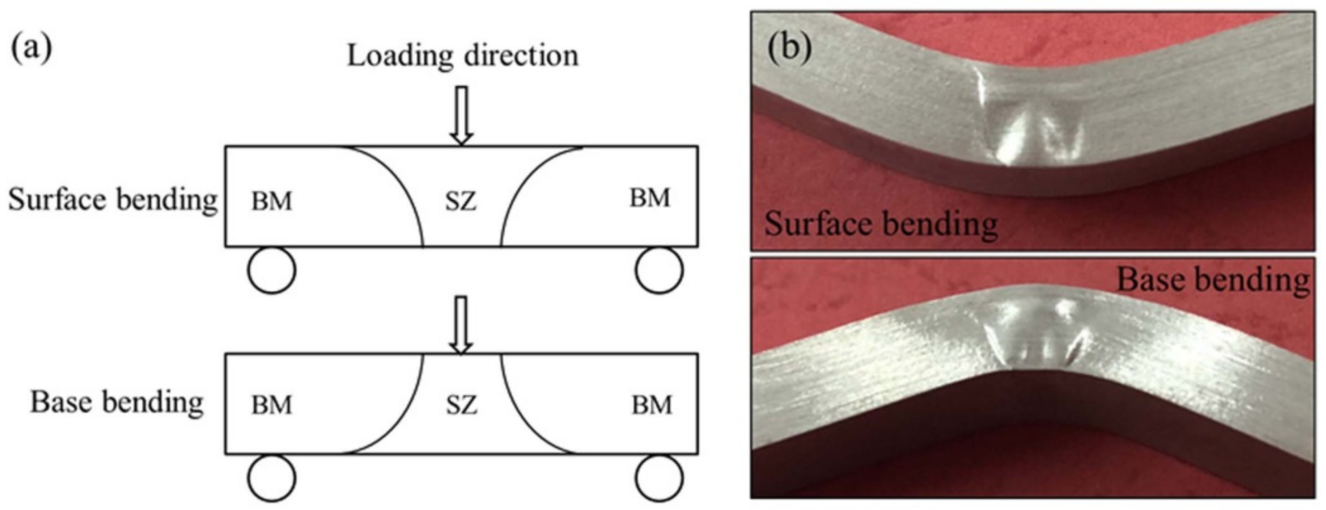
Figure 3.
The whole morphology (a) and microstructure characteristics in different zones (b) position 1 (c) position 2 (d) position 3 of the FSWed AZ31 Mg alloy joint. (2–15° and >15°grain boundary were marked by white and black, respectively).
Figure 3.
The whole morphology (a) and microstructure characteristics in different zones (b) position 1 (c) position 2 (d) position 3 of the FSWed AZ31 Mg alloy joint. (2–15° and >15°grain boundary were marked by white and black, respectively).

Figure 4.
Pole figures in different zones (a) position 1 (b) position 2 (c) position 3 of the FSWed AZ31 Mg alloy joint.
Figure 4.
Pole figures in different zones (a) position 1 (b) position 2 (c) position 3 of the FSWed AZ31 Mg alloy joint.

Figure 5.
Engineering stress-strain curves of FSWed AZ31 Mg alloy joints during (a) tension and compression (b) surface bending and base bending.
Figure 5.
Engineering stress-strain curves of FSWed AZ31 Mg alloy joints during (a) tension and compression (b) surface bending and base bending.

Figure 6.
Microstructure characteristics of the FSWed AZ31 Mg joint after bending with a strain of 5% (a) surface test sample and (b) base test sample.
Figure 6.
Microstructure characteristics of the FSWed AZ31 Mg joint after bending with a strain of 5% (a) surface test sample and (b) base test sample.
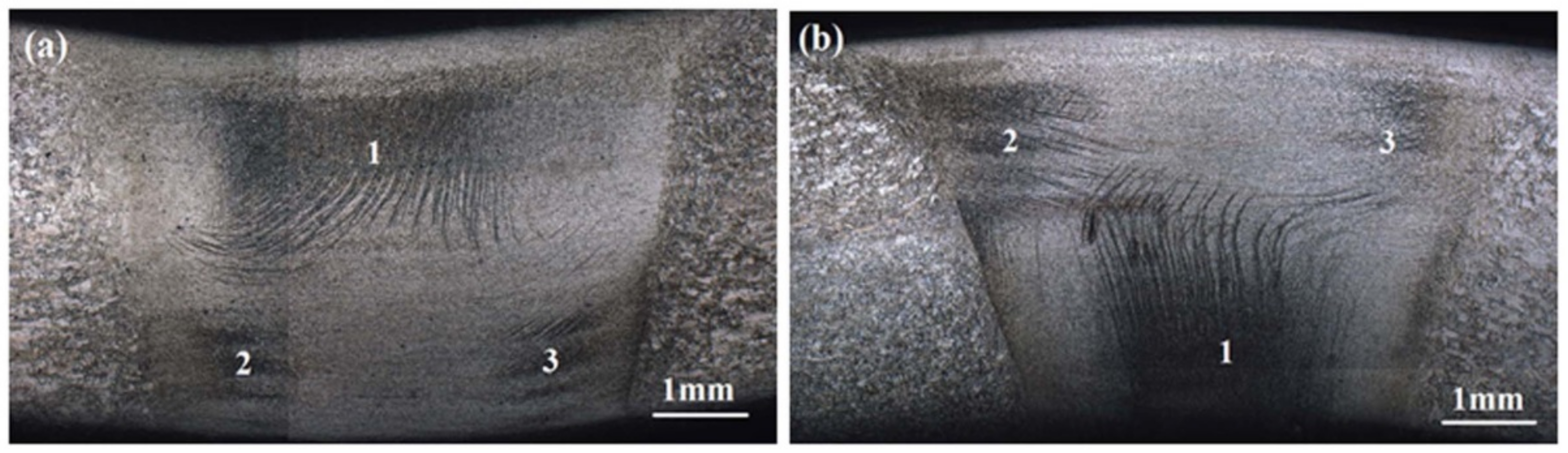
Figure 7.
The schematic diagram of the stress distribution, twinning activation and surface change of welding joint.
Figure 7.
The schematic diagram of the stress distribution, twinning activation and surface change of welding joint.

Figure 8.
Microstructure in different region of the FSWed AZ31 Mg joint after surface bending and base bending with strain of 5% (a,b) region 1, (c,d) region 2 and (e,f) region 3.
Figure 8.
Microstructure in different region of the FSWed AZ31 Mg joint after surface bending and base bending with strain of 5% (a,b) region 1, (c,d) region 2 and (e,f) region 3.

Figure 9.
The electron back scatter diffraction (EBSD) analysis from below to top in region 1 of FSW AZ31 joint after base bending (a,c,e,g) IPF maps (b,d,f,h) grain boundary maps. ~ 56°-blue, ~86°-red, 2–15°-green, >15°-black.
Figure 9.
The electron back scatter diffraction (EBSD) analysis from below to top in region 1 of FSW AZ31 joint after base bending (a,c,e,g) IPF maps (b,d,f,h) grain boundary maps. ~ 56°-blue, ~86°-red, 2–15°-green, >15°-black.
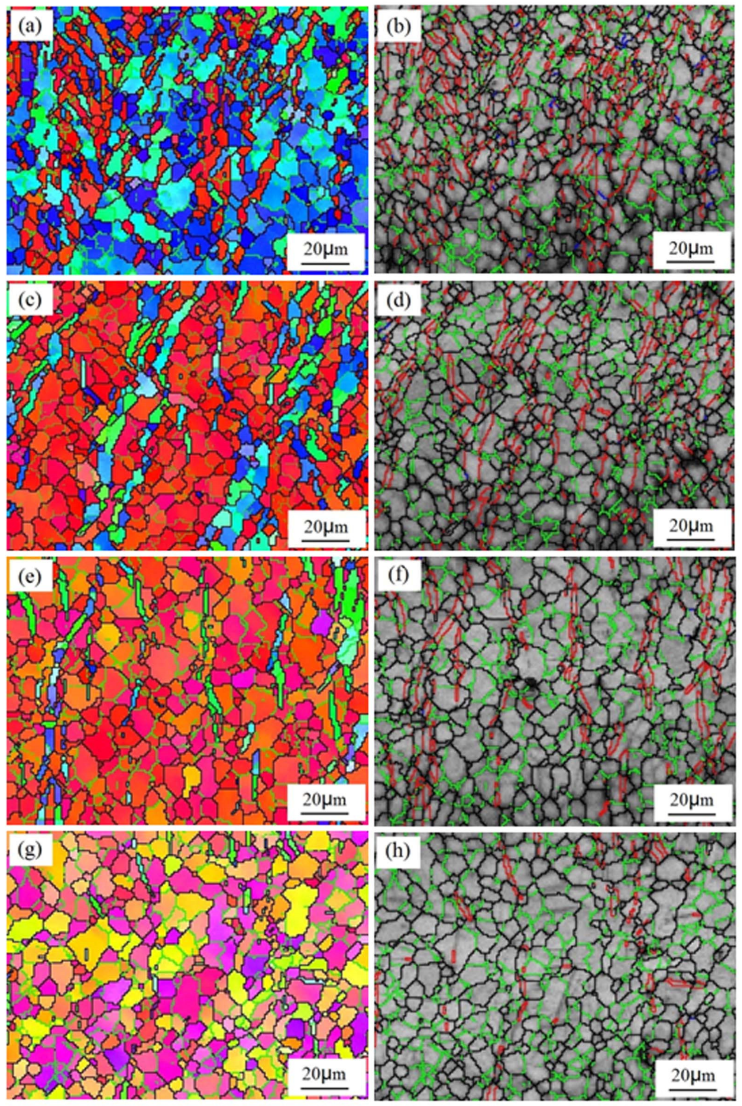
Figure 10.
The grain boundary misorientation distribution in different positions in region 1 of FSW AZ31 joint after base bending (a)→(d) from below to top.
Figure 10.
The grain boundary misorientation distribution in different positions in region 1 of FSW AZ31 joint after base bending (a)→(d) from below to top.

Figure 11.
The pole figures in different positions in region 1 of FSW AZ31Mg alloy joint after base bending (a)→(d) from below to top.
Figure 11.
The pole figures in different positions in region 1 of FSW AZ31Mg alloy joint after base bending (a)→(d) from below to top.

Figure 12.
The EBSD analysis of FSW joint after base bending to 5% (a) crystallographic orientation map and (b) misorientation distribution along the lines L1.
Figure 12.
The EBSD analysis of FSW joint after base bending to 5% (a) crystallographic orientation map and (b) misorientation distribution along the lines L1.


Table 1.
The geometric parameters of grains P1, T1 and P2.
| Gains | P1 | T1 | P2 |
|---|---|---|---|
| Φ1(deg) | 57.7 | 122.0 | 56.9 |
| Φ(deg) | 152.2 | 84.1 | 154.5 |
| Φ2(deg) | 25.7 | 8.8 | 25.2 |
© 2020 by the authors. Licensee MDPI, Basel, Switzerland. This article is an open access article distributed under the terms and conditions of the Creative Commons Attribution (CC BY) license (http://creativecommons.org/licenses/by/4.0/).
Share and Cite
MDPI and ACS Style
Qin, F.; Li, Y.; Zheng, J. The Activation and Evolution of Twinning during Bending of Friction Stir Welded AZ31 Magnesium Alloys. Metals 2020, 10, 139. https://doi.org/10.3390/met10010139
AMA Style
Qin F, Li Y, Zheng J. The Activation and Evolution of Twinning during Bending of Friction Stir Welded AZ31 Magnesium Alloys. Metals. 2020; 10(1):139. https://doi.org/10.3390/met10010139
Chicago/Turabian StyleQin, Fengming, Yajie Li, and Jianjun Zheng. 2020. "The Activation and Evolution of Twinning during Bending of Friction Stir Welded AZ31 Magnesium Alloys" Metals 10, no. 1: 139. https://doi.org/10.3390/met10010139
Note that from the first issue of 2016, this journal uses article numbers instead of page numbers. See further details here.