Article

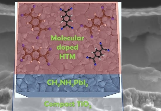
Molecular Doping for Hole Transporting Materials in Hybrid Perovskite Solar Cells

1
School of Engineering and Materials Science (SEMS), Queen Mary University of London, Mile End Road, London E1 4NS, UK
2
Department of Materials Science and Milan-Bicocca Solar Energy Research Center–MIB-Solar University of Milan-Bicocca, Via Cozzi 55, 20125 Milano, Italy
3
Department of Mathematics and Physics “E. De Giorgi” University of Salento, 73100 Lecce, Italy
4
Istituto di Nanotecnologia CNR-Nanotec, Polo di Nanotecnologia c/o Campus Ecotekne via Monteroni, 73100 Lecce, Italy
*
Author to whom correspondence should be addressed.
Metals 2020, 10(1), 14; https://doi.org/10.3390/met10010014
Submission received: 4 December 2019 / Revised: 14 December 2019 / Accepted: 16 December 2019 / Published: 20 December 2019
(This article belongs to the Special Issue Application and Characterisation of Hybrid Halide Perovskites)

Abstract

:
Hybrid lead halide perovskites have been revolutionary in the photovoltaic research field, reaching efficiencies comparable with the most established photovoltaic technologies, although they have not yet reached their competitors’ stability. The search for a stable configuration requires the engineering of the charge extraction layers; in this work, molecular doping is used as an efficient method for small molecules and polymers employed as hole transport materials in a planar heterojunction configuration on compact-TiO2. We proved the viability of this approach, obtaining significantly increased performances and reduced hysteresis on compact titania-based devices. We investigated the photovoltaic performance correlated to the hole transport material structure. We have demonstrated that the molecular doping mechanism is more reliable than oxidative doping and have verified that molecular doping in polymeric hole transport materials leads to highly efficient perovskite solar cells, with long-term stability.

Graphical Abstract

1. Introduction

Hybrid lead halide perovskites are revolutionary materials for a wide range of optoelectronic and electronic applications [1,2,3]. In the photovoltaic research field, they have shown efficiencies comparable with the most established photovoltaic technologies, overcoming the thin-film technologies, although perovskite-based solar cells have not yet reached their competitors’ stability [1,4,5,6]. A step towards achieving devices with long-term stability has recently been achieved with mixed-cation lead mixed-halide perovskites, such as (HC(NH2)2)0.83Cs0.17Pb(I0.6Br0.4)3 [7,8]. Therefore, the search for the most stable configuration is, nowadays, dominated by the search for charge extractor materials that can stabilise the solar cell performance [4,9]. In conventional device architecture (substrate, cathode, electron transporting material (ETM), hybrid perovskite, hole transporting material (HTM), anode), the most commonly employed HTM, due to its significant solubility and excellent hole mobility, is Spiro-OMeTAD ((2,2′,7,7′-Tetrakis N, N-di-p-methoxyphenylamine)-9,9′-spirobifluorene) [10,11]. Spiro-OMeTAD has given excellent results—the doping occurs by the oxidation of the complex that it forms with the additive lithium bis(trifluoromethanesulfonyl)imide (LiTFSI) in an open system condition. However, it is hard to collect consistent results, because the amount of oxidised Spiro-OMeTAD depends on external factors (e.g., oxygen in the active layer, light intensity, humidity, and room temperature). The fluctuation of the oxidised Spiro-OMeTAD concentration affects device stability and reproducibility [12], and the Li+ cations can easily migrate across the perovskite film and reach the ETM interface, with a massive impact on the hysteresis [13].
In order to address this issue, other organic materials have been successfully employed as HTMs in perovskite solar cells, such as poly(3-hexylthiophene-2,5-diyl) (P3HT) [14] which has a higher hole mobility (up to 0.1 cm2 V−1 s−1 in LiTFSI-doped P3HT compared to 10−4 cm2 V−1 s−1 in LiTFSI-doped Spiro-OMeTAD) [15]. Lately, polymeric HTMs are attracting attention, because the film structure is not affected by the working operation condition, and they can form an adequate barrier to prevent gold migration from the back contact [16]. With the aim of decreasing production costs, interest in the study of P3HT as a HTM in perovskite solar cells has increased; it is a well-known material, and it is easy to coat [14,17,18,19,20]. Undoped P3HT has proven to be extremely effective; when it was tested on perovskite films with very low defect densities and an engineered interface, it achieved high solar conversion efficiencies [14,21]. Still, long-term stability remains an issue. The most remarkable result to date is that after 1008 h under 85% relative humidity at room temperature P3HT retained 80% of its first efficiency [14]. A way to increase stability is to exploit the molecular doping methodology. Doping technology is extensively used in photovoltaic and electroluminescent devices, based on inorganic, organic and hybrid materials, to enhance the conductivity of the transporting layers [22]. Additionally, doping has proven to be an effective way to increase stability in organic photovoltaic devices, and a large variety of molecular species can serve as dopants in organic semiconductors [23,24,25].
In this study, 2,3,5,6-Tetrafluoro-7,7,8,8-tetracyanoquinodimethane (F4-TCNQ) was employed [26,27,28,29] as an additive in a small molecule HTM (Spiro-OMeTAD) and polymer HTM (P3HT). F4-TCNQ is a strong electron acceptor and is widely used as a hole selective layer or as an additive in p-type doping [26,30,31,32,33,34,35,36]. F4-TCNQ is commonly used to minimise the hole injection barrier, and it has been proven that F4-TCNQ doping generates a polaron charge-transfer complex that increases HTM conductivity and decreases the charge recombination [37]. Huang et al. [38] reported using F4-TCNQ:Spiro-OMeTAD as a HTM layer which improved the air stability of perovskite solar cells. Their device reached 10.6% photon conversion efficiency, PCE, comparable to LiTFSI doping (PCE = 12.7%). However, the F4-TCNQ-based device retained 85% of this PCE after 72 h and 60% after one week of the first performance, compared with the LiTFSI-based device that retained 20% after 72 h and 10% after one week of the initial performance. They attributed the increased stability to the substitution of hygroscopic LiTFSI with the non-hygroscopic F4-TCNQ. Encouraged by the results mentioned above, we tested F4-TCNQ doping, in various concentrations, in the planar heterojunction configuration on compact-TiO2 (c-TiO2:PHJ, Figure 1 in the relief); in this device architecture, the ETM is only composed of a layer of about 80 nm of titania, and no scaffold is used [39]. In order to obtain reliable CH3NH3PbI3 layers, these layers were grown following the procedure published by the authors elsewhere [40]. As demonstrated by the high efficiencies that the fine engineering of the absorber layer and its interface with the charge extraction layers can provide [14,41,42], we employed a compact perovskite film with reduced surface defects and large grain size, in order to realise devices with a photovoltaic performance that is independent of the voltage scan direction. A scanning electron microscopy (SEM) image of the employed perovskite film is shown in Figure 1b.

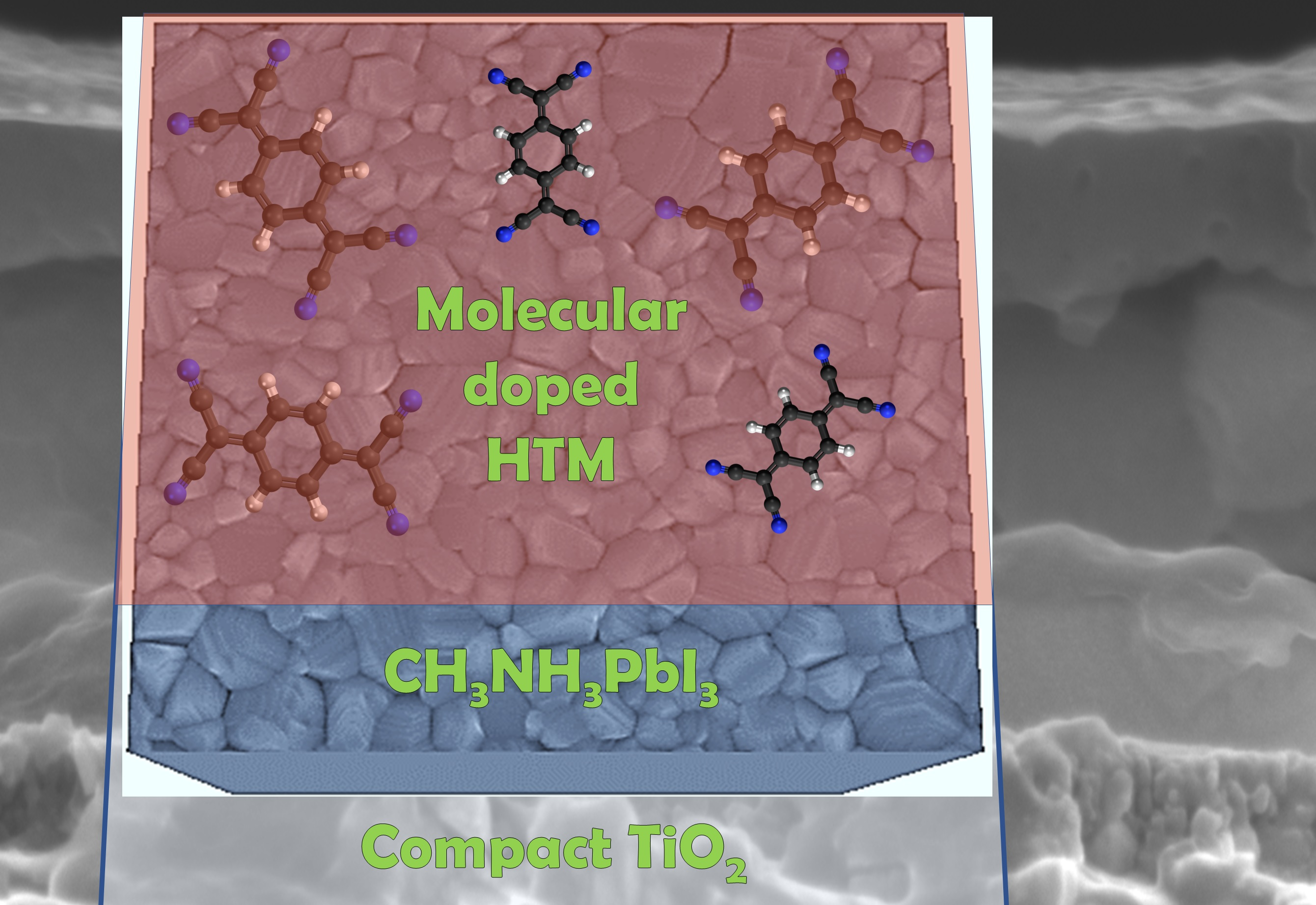
2. Materials and Methods

Hybrid perovskite solar cells were prepared in a planar heterojunction configuration on compact-TiO2 (c-TiO2:PHJ) (relief in Figure 1), and LiTFSI-doped Spiro-OMeTAD was employed as a control device [40]. Fluorine tin oxide (FTO)/glass were employed for the substrate and partially etched. Substrate cleaning was performed using pure water, acetone and isopropanol in an ultrasonic bath. Next they were immersed in a TL1 washing solution, which was heated to 80 °C (10 min). Then they were rinsed using pure water. The TiO2 was synthesised by twice spin coating 0.15 M of titanium diisopropoxidebis (acetylacetonate) solution in 1-butanol and once spin coating 0.3 M of titanium diisopropoxidebis (acetylacetonate) solution in 1-butanol. After each deposition, the sample was heated on a hot plate at 125 °C for 5 min and then heated for 2 h in an oven at 520 °C [40].
CH3NH3I was synthesised according to the procedure reported in the literature [40]. The 2 M CH3NH3PbI3 solution was prepared according to the procedure published by the authors elsewhere [40]: (i) the PbI2 pellets were solved in a mixture of γ-butyrolactone and dimethyl sulfoxide for 1 h at 90 °C, and the CH3NH3I powder was added, (ii) the mixture of PbI2 pellets and CH3NH3I powder was stirred for 30 min at 70 °C and kept overnight at 60 °C. The day after, 200 μL was dropped and spin-coated on the TiO2/FTO at 1000 and 4000 rpm, respectively, for 20 and 60 s. During the final spin-coating step, 200 μL of dichloromethane was dropped. The samples were then annealed for 75 min at 100 °C on a hot plate and subjected to 9.0 × 10⁻⁷ mBar for 4 h [40].
The Spiro-OMeTAD in chlorobenzene concentration was 63 mg mL−1, and it was doped by tert-butylpyridine (27.8 μL) and LiTFSI in acetonitrile solution (30.7 μL). The spin rate was 2500 rpm for 45 s, in order to produce a layer of 90 nm. Spiro-OMeTAD doped with F4-TCNQ (Sigma-Aldrich) was prepared in 0.1, 0.5, 1 and 5 wt %. The doped solutions were spun at a rate of 2500 rpm for 45 s. We, therefore, extended this approach to P3HT (Regioregularity ≥ 98%, Sigma-Aldrich) as proof of concept, in which we used a 15 mg mL−1 solution in chlorobenzene that was stirred at 80 °C for 10 min. Once cooled to room temperature, 100 µL of the filtered solution was spin-coated onto the perovskite film at 600 and 2000 RPM for 12 and 40 s, respectively [17]. The coated films were then annealed on a hot plate set at 100 °C for 10 min to increase the order in the P3HT film structure [43]. The P3HT film thickness was about 60 nm. Various amounts of F4-TCNQ were added to the P3HT solution to change the doping concentration. The coating of the perovskite films was unchanged for both types of HTM-doped layers. Finally, 80 nm Au electrodes were grown by thermal evaporation.
A MERLIN Zeiss field emission gun scanning electron microscopy, FEGSEM (Kohen, Germany), instrument was employed for scanning electron microscopy at an accelerating voltage of 5 kV. The monochromator Omni 300 LOT ORIEL, with a single grating in Czerny–Turner optical design, in AC mode with a chopping frequency of 13 Hz and a light bias (1 sun) applied was used for recording the external quantum efficiency. A Keithley 2400 Source Measure Unit and a solar simulator Spectra Physics Oriel 150 W, with an AM1.5G filter set, were used to measure the current–voltage characteristics. Devices were tested inside and outside the glovebox, without encapsulation. Devices were tested with a humidity of 50% under ambient conditions. The reported performances were registered after 30 min in air. Shunt resistance (Rsh) and series resistance (Rs) have been evaluated by assuming the single diode model [44]; Rsh can be approximated by the negative of the inverse slope of the characteristic curve where the voltage is null, and Rs can be approximated by the negative of the inverse slope of the characteristic curve where the current is null.

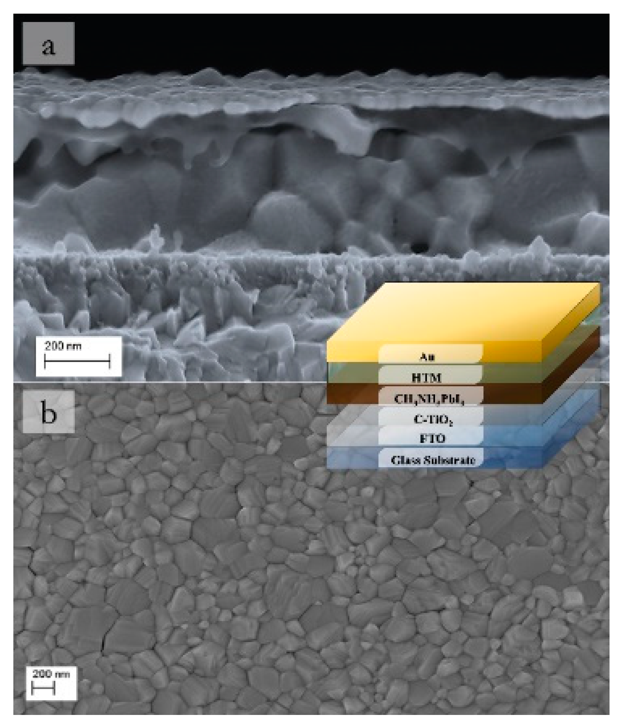
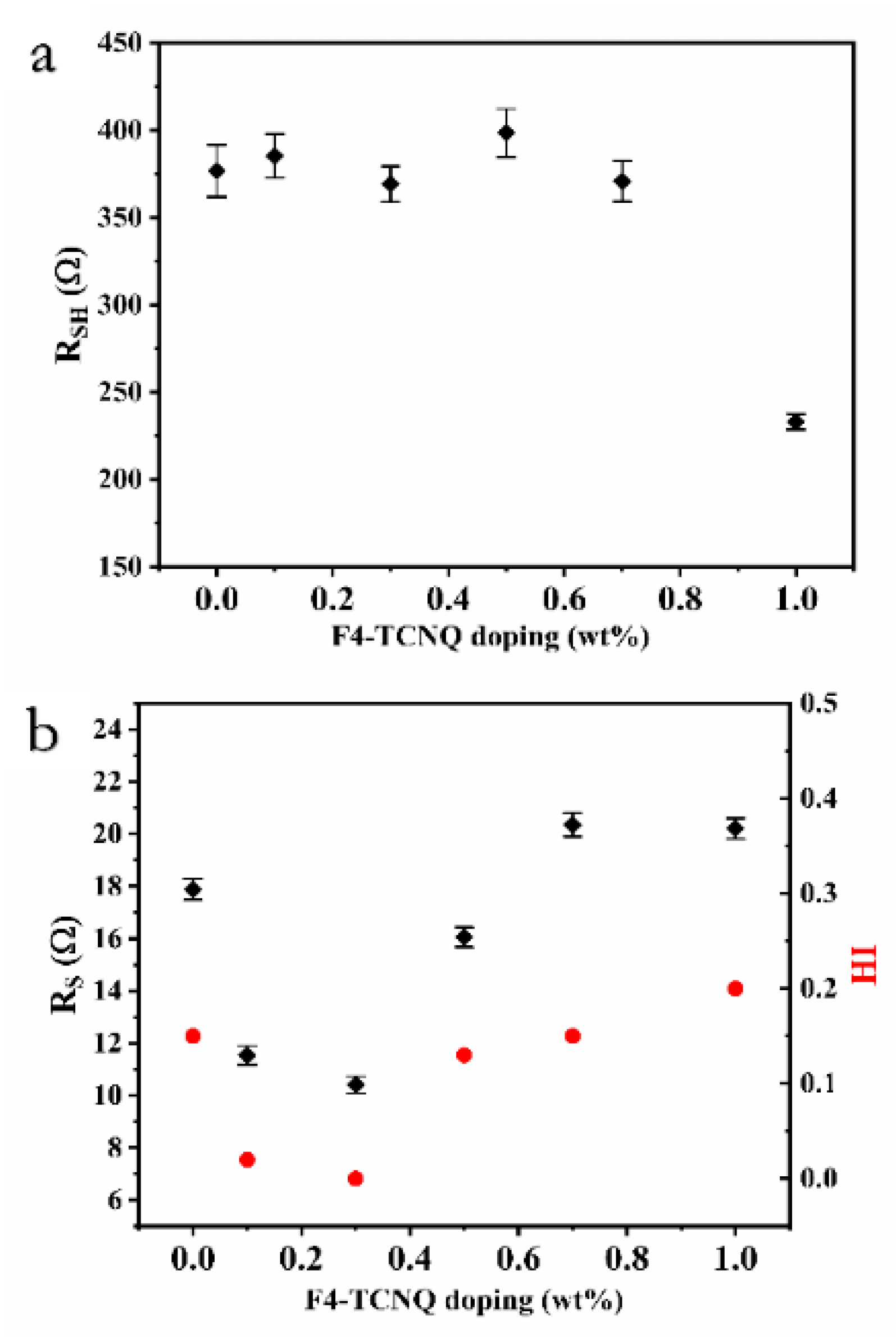
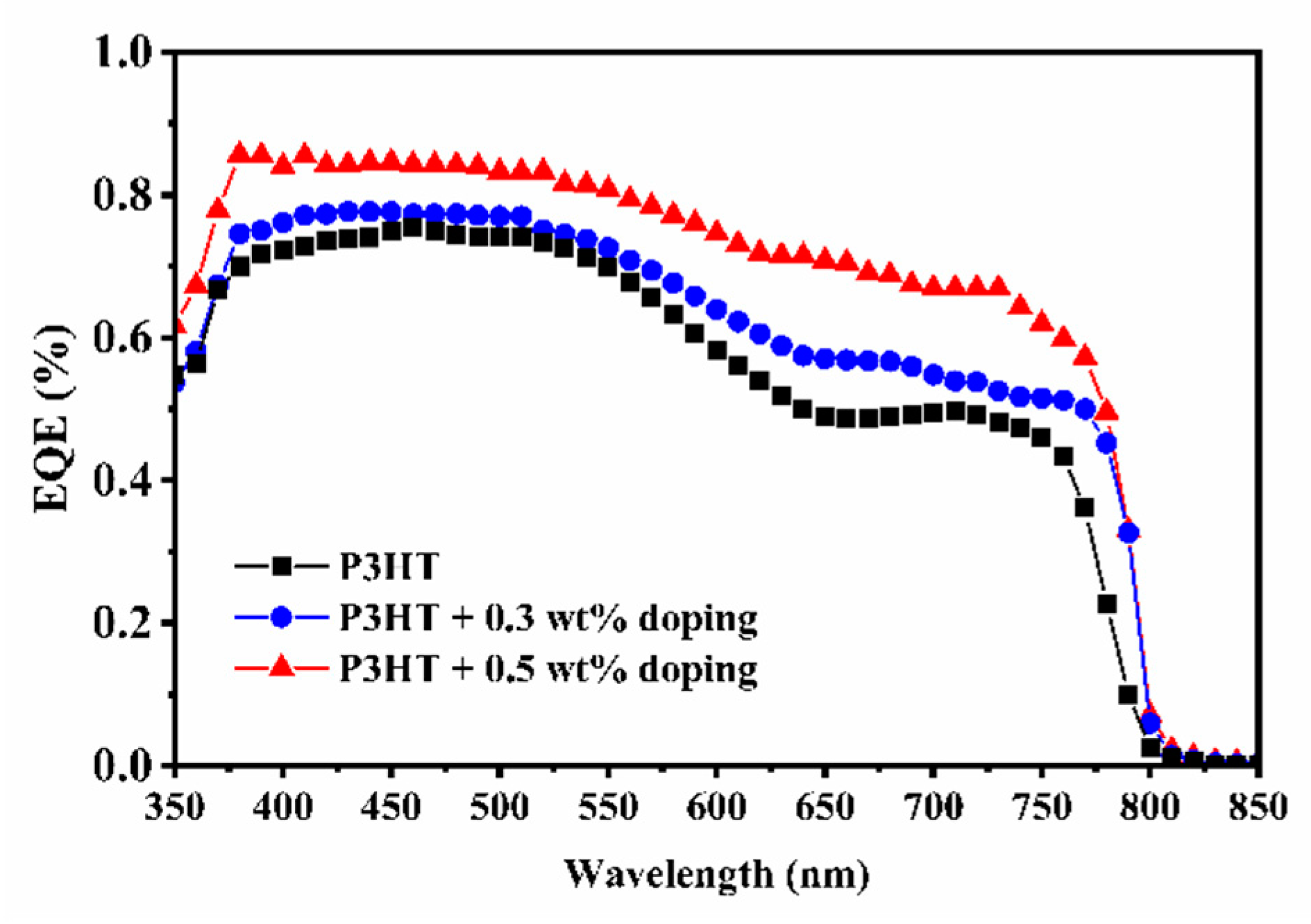
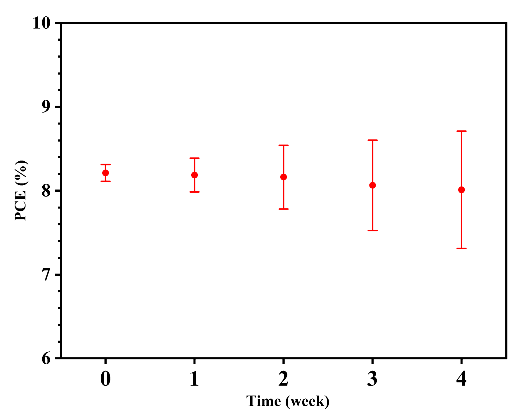
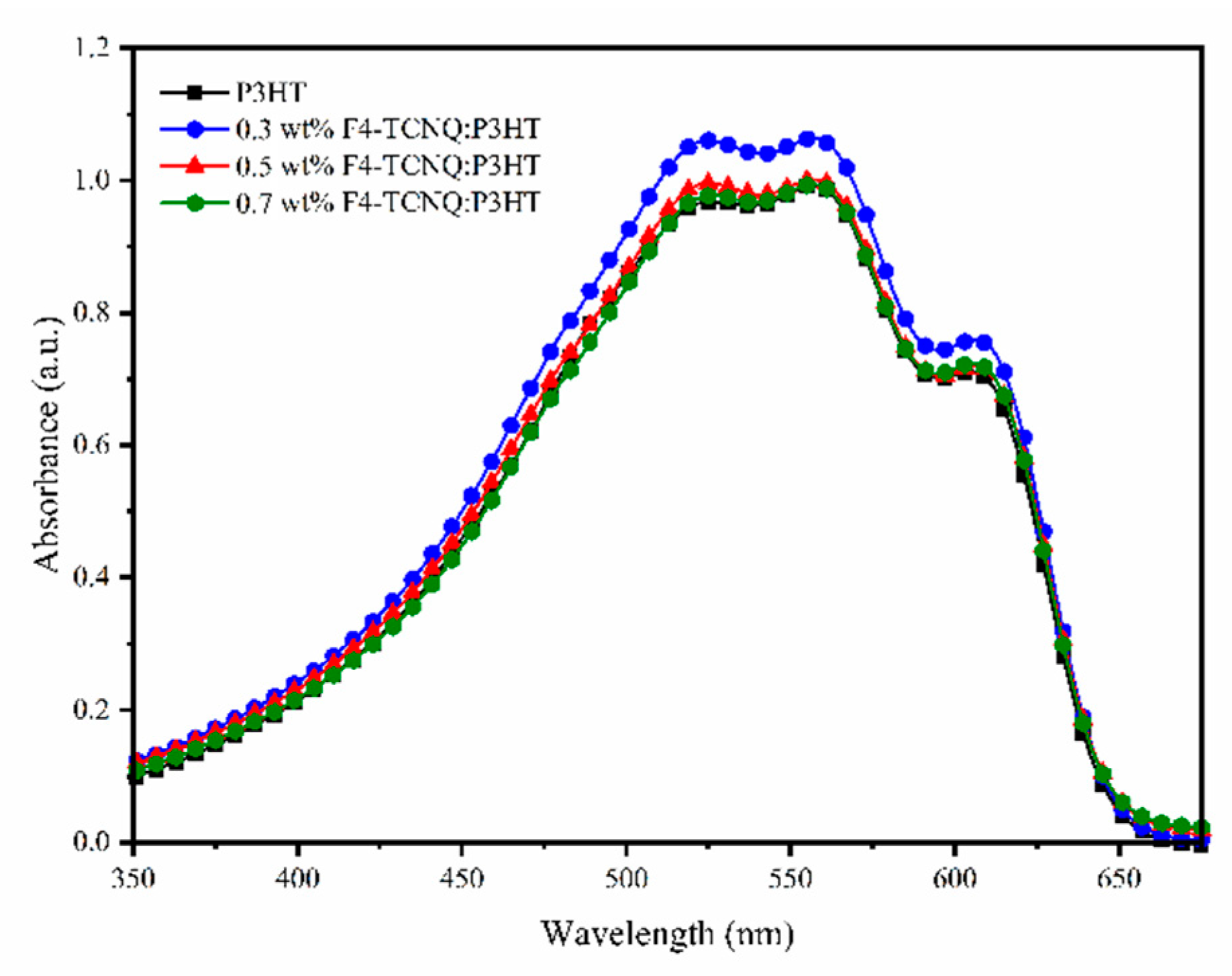
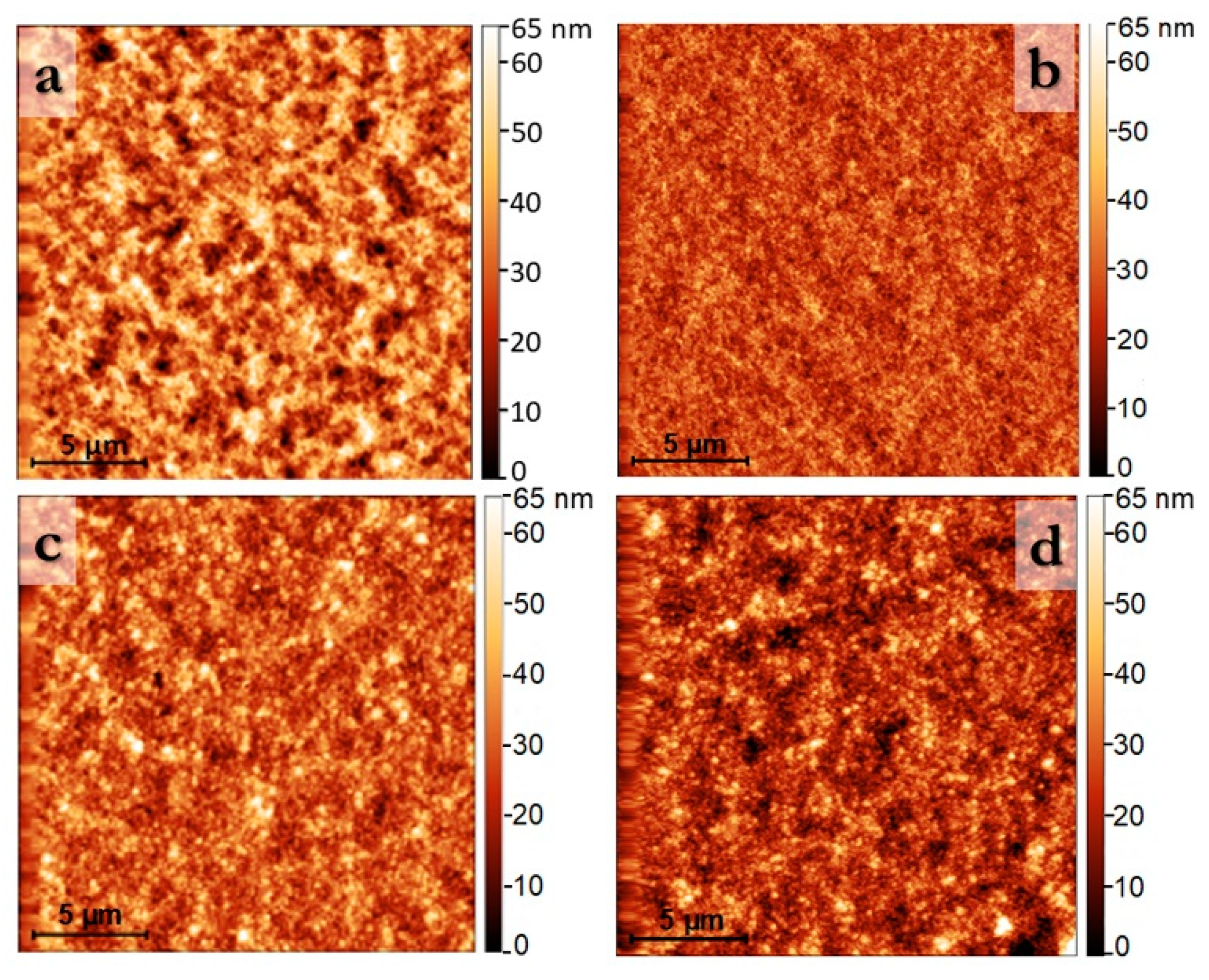
3. Results and Discussion

In order to verify the reliability of each set of measurements, devices employing undoped and F4-TCNQ-doped Spiro-OMeTAD were fabricated; LiTFSI-doped Spiro-OMeTAD was also tested as a control device. F4-TCNQ 0.1 wt % doping is effective, compared with undoped Spiro-OMeTAD. The significant increase in the current of the F4-TCNQ-doped films induced an almost two-fold increased efficiency, reaching a similar PCE as the LiTFSI doping method. This result demonstrates the efficient F4-TCNQ doping effect, and notably, the 0.1 wt % device did not present hysteresis (best devices are shown in Table 1). The average PCEs on four devices were 6.38 ± 0.45%, 11.60 ± 0.15%, 8.79 ± 0.30%, 7.63 ± 0.24% and 6.45 ± 0.30% for undoped (0 wt %), 0.1 wt %, 0.5 wt %, 1 wt % and 5 wt % F4-TCNQ doping, respectively. By increasing the molecular doping to 0.5 wt %, a sharp drop in current was clear, which was accompanied by a drop in potential over 1 wt % doping. This decrease in performance was predictable, considering the tendency of F4-TCNQ to create aggregates in mixtures with other molecules [45]. It has been shown that beyond specific doping, the increase in photocurrent is accompanied by an increase in series resistance, caused by insulating aggregates [43,46,47,48]. Therefore, we can conclude that p-type molecular doping by careful tuning of the dopant weight per cent is promising in enhancing the photovoltaic performance of perovskite cells. Although, for Spiro-OMeTAD, the control LiTFSI-based device exhibited superior performance (short-circuit current density, Jsc = 19.67; open circuit voltage, Voc = 1.08; fill factor, FF = 0.67; PCE = 14.23; hysteresis index HI = 0.00), as already reported previously [38].
We then measured devices with F4-TCNQ:P3HT as the HTM layer. The F4-TCNQ lowest unoccupied molecular orbital (LUMO) is deeper than the P3HT highest occupied molecular orbital (HOMO), inducing efficient electron transfer and an ionised complex (P3HT+) that increases the electrical conductivity [36,45]. The doping effect confirmed in Spiro-OMeTAD was also observed in the P3HT (best devices are shown in Table 1 and Figure 2). The average PCEs on four devices were 7.00 ± 0.19%, 7.90 ± 0.13%, 8.21 ± 0.10%, 9.53 ± 0.24%, 5.80 ± 0.40% and 5.55 ± 0.48%for undoped (0 wt %), 0.1 wt %, 0.3 wt %, 0.5 wt %, 0.7 wt % and 1 wt % F4-TCNQ doping, respectively. The current increased with the dopant concentration up to 0.5 wt % and then it decreased. In the case of 0.1 and 0.3 wt % doping, an excellent balance between current and voltage was achieved, clearly expressed by the improvement of the fill factor (FF). By raising the molecular doping, a worsening in the overall performances occurred. The hysteresis in the current vs voltage measurements reappeared for doping at 0.5 wt %, reaching 0.20 for the 1 wt % doping. For the intermediate doping, 0.3 wt %, the charge extraction has been shown to be so effective that the hysteresis in the measures is squeezed [50,51,52]. We can assume that, once a certain percentage of doping has been reached, aggregates will start to be created at the interface, affecting the hysteresis. By further increasing the doping, it was evident that the worsening of the performance was due to the short-circuit current lowering and FF reduction (Figure 2).
The fill factor is affected by the shunt resistance (Rsh), series resistance (Rs), recombination current and reverse saturation current [44]. Here we give a simple evaluation of Rsh and Rs, taking into consideration the slopes of the characteristic curves where the voltage and current are null, respectively. Even from this trivial evaluation (Figure 3), relevant information can be obtained: (i) Rsh remained comparable along the series, except for the worst-performing devices, i.e., 1 wt % doping, in which the shunt resistance decreased, indicating that a leakage path for current flow had arisen [44] and (ii) Rs and HI followed the same trend, supporting the assumption that the optimal doping level is obtained when the increase in the charge extraction is still able to balance the detrimental effect of aggregate formation at the interface between the charge extraction and the active layers.
External quantum efficiency confirmed the photovoltaic performances (Figure 4). The integrated current, Jsc, was found to be 15.45, 16.57 and 19.18 mA cm−2 for undoped P3HT, 0.3 wt % doped P3HT and 0.5 wt % doped P3HT, respectively, ensuring the reliability of the photovoltaic characterisation. The more significant gain that comes from the doping was visible for wavelengths greater than 600 nm; this is compatible with the assumption that the P3HT Fermi level shifts close its HOMO level [53,54].
The characteristic curves’ acquisitions in time, in nitrogen and air, and for pristine and 0.3 wt % doped P3HT-based devices are shown in Figure 5. The drastic performance improvement is related to the P3HT interaction with oxygen, quickly forming a charge-transfer complex, that increases the hole concentration [55,56]. The addition of F4-TCNQ led to a further slip of the P3HT Fermi level near to its HOMO level [53,54], increasing the depletion layer built-in voltage and, therefore, improving the device performances [55]. The doping effect was also apparent when a 0.3 wt % doped P3HT was not exposed to air (Figure 5). The performance was remarkably higher than the pristine one, and the oxygen doping effect on P3HT was mitigated. These results confirm that p-type doping of P3HT with F4-TCNQ acts as an efficient HTM layer in solar-cell perovskites. We suggest that the P3HT stability in air was improved by the P3HT bonding with F4-TCNQ, which started in the precursor solution and evolved in a semi-crystalline phase that may be less inclined to react with oxygen.
In Figure 6, the average PCEs in time for four devices employing 0.3 wt % F4-TCNQ:P3HT, stored in the dark in a nitrogen glove box and measured after 30 min in air, are reported. On average they retained 99% PCE after one week and 97% after one month of the first performance, showing remarkable durability.
In order to investigate the nature of this increase in performance, we investigated the optical and morphology properties of the molecular-doped HTM thin film. The UV–Vis absorption spectra (Figure 7) did not show the polaronic bands characteristic of the heavily doped P3HT, which is consistent with the weak doping regime of F4-TCNQ: P3HT films [57]. Note that P3HT–F4TCNQ do form a charged complex even in the weak doping regime [57], which explains the slight improvement in electrical conductivity of F4-TCNQ: P3HT-based devices.
The surface roughness, Rq, calculated by analysing the atomic force microscopy, AFM, images in Figure 8, was 11, 6, 8 and 9 nm for the pristine P3HT, 0.3 wt %, 0.5 wt % and 0.7 wt % F4-TCNQ:P3HT, respectively. This slight increase in the film roughness is consistent with previous work on F4-TCNQ:P3HT films in the weak doping regime [57,58]. High dopant concentrations can compromise the P3HT crystalline structure, making it amorphous, and so increasing the scattering centres and the density of traps [53]. Gao et al. [59], reported that the formation of J-aggregate makes the polymer backbone more rigid. They suggested that F4-TCNQ adds holes to the polymer, shifting the equilibrium in favour of aggregated state formation. Considering this and studying the doping aggregation, Jacobs et al. [58] concluded that the segregation of dopant, and the resulting pathways for the charge conduction, is responsible for the higher conductivities but only at low doping levels. In a high doping condition, F4-TCNQ forms isolated domains; therefore, most of the charge carriers remain too strongly bound to be available for the electrical conduction [60]. The reported F4-TCNQ:P3HT-based devices with a dopant concentration higher than 0.5 wt % showed a decrease in performance due to the generation of aggregates acting like traps for the charge carriers, affecting hysteresis and performance. In 0.3 wt % molecular-doped P3HT, the loss in charge carriers caused by the aggregate formation was still well balanced by the charge extraction increase, leading to devices with high performance and without hysteresis.

4. Conclusions

F4-TCNQ was employed as an additive in a small molecule and polymer HTM. We tested F4-TCNQ doping, in various concentrations, in the c-TiO2: PHJ configuration. We employed a pinhole-free CH3NH3PbI3 layer with reduced surface defects and large grain size, which can generate high photovoltaic performance, not affected by the direction of the voltage scan. We have confirmed that the molecular doping of the HTM is highly effective in using both Spiro-OMeTAD and P3HT but above all that F4-TCNQ employment in P3HT-based devices increases and stabilises performance. F4-TCNQ doping generates the ionised complex P3HT+, which increases the P3HT conductivity and decreases the charge recombination. We have demonstrated that a molecular doping mechanism is more reliable than oxidation doping, using LiTFSI: Spiro-OMeTAD and pristine P3HT. We have shown that F4-TCNQ doping could also mitigate the oxygen effect on P3HT. We attribute the increase in conductivities to the segregation of dopant but only at low doping levels, in order to avoid the formation of aggregates at the interface between the perovskite and the HTM which firstly affects the hysteresis and then the overall performance. We have verified that the employment of F4-TCNQ in P3HT devices stabilises performance, making the solar cell capable of delivering a high performance over a long time. We are confident that fine optimisation and engineering of F4-TCNQ doping in P3HT-based perovskite solar cells would lead to highly efficient devices with long-term stability.

Author Contributions

Conceptualisation, V.T., T.D., A.R. and S.C.; methodology, V.T. and S.C.; validation, V.T., A.R. and S.C.; formal analysis, V.T. and T.D.; investigation, V.T. and N.M.; data curation, V.T. and N.M.; writing—original draft preparation, V.T. and T.D.; writing—review and editing, V.T., T.D. and O.F.; visualisation, V.T.; supervision, O.F., A.R. and S.C.; project administration, A.R. and V.T.; funding acquisition, V.T., O.F., A.R. and S.C. All authors have read and agreed to the published version of the manuscript.

Funding

V.T. acknowledges the European Union’s Horizon 2020 research and innovation programme under the Marie Skłodowska-Curie grant agreement, N° 798271. S.C. acknowledges Regione Puglia and ARTI for funding the future in research (FIR) project “PeroFlex”, project no. LSBC6N4. A.R. gratefully acknowledges the Scientific Independence of Young Researchers (SIR) project “Two-Dimensional Colloidal Metal Dichalcogenides-Based Energy-Conversion Photovoltaics” (2D ECO), Bando SIR 2014 MIUR Decreto Direttoriale 23 Gennaio 2014 no. 197 (project number RBSI14FYVD, CUP: B82I15000950008) for funding. O.F. acknowledges the Royal Society for his University Research Fellowship (UF140372).

Acknowledgments

The authors acknowledge Sonia Carallo for technical support.

Conflicts of Interest

The authors declare no conflict of interest. The funders had no role in the design of the study; in the collection, analyses, or interpretation of data; in the writing of the manuscript; or in the decision to publish the results.

References

  1. Colella, S.; Mazzeo, M.; Rizzo, A.; Gigli, G.; Listorti, A. The bright side of perovskites. J. Phys. Chem. Lett. 2016, 7, 4322–4334. [Google Scholar] [CrossRef] [PubMed]
  2. Sutherland, B.R.; Sargent, E.H. Perovskite photonic sources. Nat. Photonics 2016, 10, 295–302. [Google Scholar] [CrossRef]
  3. Zhang, W.; Eperon, G.E.; Snaith, H.J. Metal halide perovskites for energy applications. Nat. Energy 2016, 1, 16048. [Google Scholar] [CrossRef]
  4. Snaith, H.J. Present status and future prospects of perovskite photovoltaics. Nat. Mater. 2018, 17, 372–376. [Google Scholar] [CrossRef]
  5. Ansari, M.I.H.; Qurashi, A.; Nazeeruddin, M.K. Frontiers, opportunities, and challenges in perovskite solar cells: A critical review. J. Photochem. Photobiol. C Photochem. Rev. 2018, 35, 1–24. [Google Scholar] [CrossRef]
  6. The national renewable energy laboratory (NREL). Best Research-Cell Efficiency Chart. Available online: https://www.nrel.gov/pv/cell-efficiency.html (accessed on 16 December 2019).
  7. Rehman, W.; McMeekin, D.P.; Patel, J.B.; Milot, R.L.; Johnston, M.B.; Snaith, H.J.; Herz, L.M. Photovoltaic mixed-cation lead mixed-halide perovskites: Links between crystallinity, photo-stability and electronic properties. Energy Environ. Sci. 2017, 10, 361–369. [Google Scholar] [CrossRef] [Green Version]
  8. Wang, Z.; McMeekin, D.P.; Sakai, N.; van Reenen, S.; Wojciechowski, K.; Patel, J.B.; Johnston, M.B.; Snaith, H.J. Efficient and air-stable mixed-cation lead mixed-halide perovskite solar cells with n-doped organic electron extraction layers. Adv. Mater. 2017, 29, 1604186. [Google Scholar] [CrossRef]
  9. Rong, Y.; Hu, Y.; Mei, A.; Tan, H.; Saidaminov, M.I.; Seok, S.I.; McGehee, M.D.; Sargent, E.H.; Han, H. Challenges for commercializing perovskite solar cells. Science 2018, 361, eaat8235. [Google Scholar] [CrossRef] [Green Version]
  10. Salhi, B.; Wudil, Y.S.; Hossain, M.K.; Al-Ahmed, A.; Al-Sulaiman, F.A. Review of recent developments and persistent challenges in stability of perovskite solar cells. Renew. Sustain. Energy Rev. 2018, 90, 210–222. [Google Scholar] [CrossRef]
  11. Sani, F.; Shafie, S.; Lim, H.N.; Musa, A.O. Advancement on lead-free organic-inorganic halide perovskite solar cells: A review. Materials 2018, 11, 1008. [Google Scholar] [CrossRef] [Green Version]
  12. Nguyen, W.H.; Bailie, C.D.; Unger, E.L.; McGehee, M.D. Enhancing the hole-conductivity of spiro-ometad without oxygen or lithium salts by using Spiro(TFSI)2 in perovskite and dye-sensitized solar cells. J. Am. Chem. Soc. 2014, 136, 10996–11001. [Google Scholar] [CrossRef]
  13. Li, Z.; Xiao, C.; Yang, Y.; Harvey, S.P.; Kim, D.H.; Christians, J.A.; Yang, M.; Schulz, P.; Nanayakkara, S.U.; Jiang, C.-S.; et al. Extrinsic ion migration in perovskite solar cells. Energy Environ. Sci. 2017, 10, 1234–1242. [Google Scholar] [CrossRef]
  14. Jung, E.H.; Jeon, N.J.; Park, E.Y.; Moon, C.S.; Shin, T.J.; Yang, T.-Y.; Noh, J.H.; Seo, J. Efficient, stable and scalable perovskite solar cells using poly(3-hexylthiophene). Nature 2019, 567, 511–515. [Google Scholar] [CrossRef]
  15. Bi, D.; Yang, L.; Boschloo, G.; Hagfeldt, A.; Johansson, E.M.J. Effect of different hole transport materials on recombination in CH3NH3PbI3 perovskite-sensitized mesoscopic solar cells. J. Phys. Chem. Lett. 2013, 4, 1532–1536. [Google Scholar] [CrossRef]
  16. Domanski, K.; Correa-Baena, J.-P.; Mine, N.; Nazeeruddin, M.K.; Abate, A.; Saliba, M.; Tress, W.; Hagfeldt, A.; Grätzel, M. Not all that glitters is gold: Metal-migration-induced degradation in perovskite solar cells. ACS Nano 2016, 10, 6306–6314. [Google Scholar] [CrossRef]
  17. Di Giacomo, F.; Razza, S.; Matteocci, F.; D’Epifanio, A.; Licoccia, S.; Brown, T.M.; Di Carlo, A. High efficiency CH3NH3PbI(3−x)Clx perovskite solar cells with poly(3-hexylthiophene) hole transport layer. J. Power Sources 2014, 251, 152–156. [Google Scholar] [CrossRef]
  18. Zhu, Z.; Bai, Y.; Zhang, T.; Liu, Z.; Long, X.; Wei, Z.; Wang, Z.; Zhang, L.; Wang, J.; Yan, F.; et al. High-performance hole-extraction layer of sol–gel-processed nio nanocrystals for inverted planar perovskite solar cells. Angew. Chem. Int. Ed. 2014, 53, 12571–12575. [Google Scholar]
  19. Søndergaard, R.; Hösel, M.; Angmo, D.; Larsen-Olsen, T.T.; Krebs, F.C. Roll-to-roll fabrication of polymer solar cells. Mater. Today 2012, 15, 36–49. [Google Scholar] [CrossRef] [Green Version]
  20. Ratcliff, E.L.; Jenkins, J.L.; Nebesny, K.; Armstrong, N.R. Electrodeposited, “textured” poly(3-hexyl-thiophene) (e-P3HT) films for photovoltaic applications. Chem. Mater. 2008, 20, 5796–5806. [Google Scholar] [CrossRef]
  21. Abbas, H.A.; Kottokkaran, R.; Ganapathy, B.; Samiee, M.; Zhang, L.; Kitahara, A.; Noack, M.; Dalal, V.L. High efficiency sequentially vapor grown n-i-p CH3NH3PbI3 perovskite solar cells with undoped P3HT as p-type heterojunction layer. APL Mater. 2015, 3, 016105. [Google Scholar] [CrossRef] [Green Version]
  22. Genco, A.; Mariano, F.; Carallo, S.; Guerra, V.L.P.; Gambino, S.; Simeone, D.; Listorti, A.; Colella, S.; Gigli, G.; Mazzeo, M. Fully vapor-deposited heterostructured light-emitting diode based on organo-metal halide perovskite. Adv. Electron. Mater. 2016, 2, 1500325. [Google Scholar] [CrossRef]
  23. Jacobs, I.E.; Moulé, A.J. Controlling molecular doping in organic semiconductors. Adv. Mater. 2017, 29, 1703063. [Google Scholar] [CrossRef]
  24. Larrain, F.A.; Fuentes-Hernandez, C.; Chou, W.-F.; Rodriguez-Toro, V.A.; Huang, T.-Y.; Toney, M.F.; Kippelen, B. Stable solvent for solution-based electrical doping of semiconducting polymer films and its application to organic solar cells. Energy Environ. Sci. 2018, 11, 2216–2224. [Google Scholar] [CrossRef]
  25. Gatti, T.; Casaluci, S.; Prato, M.; Salerno, M.; Di Stasio, F.; Ansaldo, A.; Menna, E.; Di Carlo, A.; Bonaccorso, F. Boosting perovskite solar cells performance and stability through doping a poly-3(hexylthiophene) hole transporting material with organic functionalized carbon nanostructures. Adv. Funct. Mater. 2016, 26, 7443–7453. [Google Scholar] [CrossRef]
  26. Loiudice, A.; Rizzo, A.; Biasiucci, M.; Gigli, G. Bulk heterojunction versus diffused bilayer: The role of device geometry in solution p-doped polymer-based solar cells. J. Phys. Chem. Lett. 2012, 3, 1908–1915. [Google Scholar] [CrossRef] [Green Version]
  27. Gheno, A.; Vedraine, S.; Ratier, B.; Bouclé, J. Π-conjugated materials as the hole-transporting layer in perovskite solar cells. Metals 2016, 6, 21. [Google Scholar] [CrossRef] [Green Version]
  28. Luo, J.; Jia, C.; Wan, Z.; Han, F.; Zhao, B.; Wang, R. The novel dopant for hole-transporting material opens a new processing route to efficiently reduce hysteresis and improve stability of planar perovskite solar cells. J. Power Sources 2017, 342, 886–895. [Google Scholar] [CrossRef]
  29. Liu, D.; Li, Y.; Yuan, J.; Hong, Q.; Shi, G.; Yuan, D.; Wei, J.; Huang, C.; Tang, J.; Fung, M.-K. Improved performance of inverted planar perovskite solar cells with F4-TCNQ doped PEDOT:PSS hole transport layers. J. Mater. Chem. A 2017, 5, 5701–5708. [Google Scholar] [CrossRef]
  30. Pfeiffer, M.; Beyer, A.; Fritz, T.; Leo, K. Controlled doping of phthalocyanine layers by cosublimation with acceptor molecules: A systematic seebeck and conductivity study. Appl. Phys. Lett. 1998, 73, 3202–3204. [Google Scholar] [CrossRef]
  31. Colsmann, A.; Junge, J.; Kayser, C.; Lemmer, U. Organic tandem solar cells comprising polymer and small-molecule subcells. Appl. Phys. Lett. 2006, 89, 203506. [Google Scholar] [CrossRef]
  32. Aziz, E.F.; Vollmer, A.; Eisebitt, S.; Eberhardt, W.; Pingel, P.; Neher, D.; Koch, N. Localized charge transfer in a molecularly doped conducting polymer. Adv. Mater. 2007, 19, 3257–3260. [Google Scholar] [CrossRef]
  33. Yim, K.-H.; Whiting, G.L.; Murphy, C.E.; Halls, J.J.M.; Burroughes, J.H.; Friend, R.H.; Kim, J.-S. Controlling electrical properties of conjugated polymers via a solution-based p-type doping. Adv. Mater. 2008, 20, 3319–3324. [Google Scholar] [CrossRef]
  34. Lee, J.H.; Yoon, S.; Ko, M.S.; Lee, N.; Hwang, I.; Lee, M.J. Improved performance of organic photovoltaic devices by doping F4-TCNQ onto solution-processed graphene as a hole transport layer. Org. Electron. 2016, 30, 302–311. [Google Scholar] [CrossRef]
  35. Hwang, S.; Potscavage, W.J., Jr.; Nakamichi, R.; Adachi, C. Processing and doping of thick polymer active layers for flexible organic thermoelectric modules. Org. Electron. 2016, 31, 31–40. [Google Scholar] [CrossRef]
  36. Zhang, Y.; Elawad, M.; Yu, Z.; Jiang, X.; Lai, J.; Sun, L. Enhanced performance of perovskite solar cells with P3HT hole-transporting materials via molecular p-type doping. RSC Adv. 2016, 6, 108888–108895. [Google Scholar] [CrossRef]
  37. Hawash, Z.; Ono, L.K.; Qi, Y. Recent advances in spiro-meotad hole transport material and its applications in organic–inorganic halide perovskite solar cells. Adv. Mater. Interfaces 2018, 5, 1700623. [Google Scholar] [CrossRef] [Green Version]
  38. Huang, L.; Hu, Z.; Xu, J.; Zhang, K.; Zhang, J.; Zhang, J.; Zhu, Y. Efficient and stable planar perovskite solar cells with a non-hygroscopic small molecule oxidant doped hole transport layer. Electrochim. Acta 2016, 196, 328–336. [Google Scholar] [CrossRef] [Green Version]
  39. Liu, M.; Johnston, M.B.; Snaith, H.J. Efficient planar heterojunction perovskite solar cells by vapour deposition. Nature 2013, 501, 395–398. [Google Scholar] [CrossRef]
  40. Trifiletti, V.; Manfredi, N.; Listorti, A.; Altamura, D.; Giannini, C.; Colella, S.; Gigli, G.; Rizzo, A. Engineering TiO2/perovskite planar heterojunction for hysteresis-less solar cells. Adv. Mater. Interfaces 2016, 3, 1600493. [Google Scholar] [CrossRef]
  41. Trifiletti, V.; Cannavale, A.; Listorti, A.; Rizzo, A.; Colella, S. Sequential deposition of hybrid halide perovskite starting both from lead iodide and lead chloride on the most widely employed substrates. Thin Solid Films 2018, 657, 110–117. [Google Scholar] [CrossRef]
  42. Guerra, V.L.P.; Altamura, D.; Trifiletti, V.; Colella, S.; Listorti, A.; Giannuzzi, R.; Pellegrino, G.; Condorelli, G.G.; Giannini, C.; Gigli, G.; et al. Implications of TiO2 surface functionalization on polycrystalline mixed halide perovskite films and photovoltaic devices. J. Mater. Chem. A 2015, 3, 20811–20818. [Google Scholar] [CrossRef]
  43. Duong, D.T.; Phan, H.; Hanifi, D.; Jo, P.S.; Nguyen, T.-Q.; Salleo, A. Direct observation of doping sites in temperature-controlled, p-doped P3HT thin films by conducting atomic force microscopy. Adv. Mater. 2014, 26, 6069–6073. [Google Scholar] [CrossRef]
  44. The physics of the solar cell. In Handbook of Photovoltaic Science and Engineering; Wiley: Chichester, West Sussex, UK, 2011; pp. 82–129.
  45. Motaung, D.E.; Malgas, G.F.; Arendse, C.J.; Mavundla, S.E.; Oliphant, C.J.; Knoesen, D. The influence of thermal annealing on the morphology and structural properties of a conjugated polymer in blends with an organic acceptor material. J. Mater. Sci. 2009, 44, 3192–3197. [Google Scholar] [CrossRef]
  46. Han, X.; Wu, Z.; Sun, B. Enhanced performance of inverted organic solar cell by a solution-based fluorinated acceptor doped P3HT:PCBM layer. Org. Electron. 2013, 14, 1116–1121. [Google Scholar] [CrossRef]
  47. Pingel, P.; Zhu, L.; Park, K.S.; Vogel, J.-O.; Janietz, S.; Kim, E.-G.; Rabe, J.P.; Brédas, J.-L.; Koch, N. Charge-transfer localization in molecularly doped thiophene-based donor polymers. J. Phys. Chem. Lett. 2010, 1, 2037–2041. [Google Scholar] [CrossRef]
  48. Deschler, F.; Riedel, D.; Deák, A.; Ecker, B.; von Hauff, E.; Da Como, E. Imaging of morphological changes and phase segregation in doped polymeric semiconductors. Synth. Met. 2015, 199, 381–387. [Google Scholar] [CrossRef] [Green Version]
  49. Calado, P.; Telford, A.M.; Bryant, D.; Li, X.; Nelson, J.; O’Regan, B.C.; Barnes, P.R.F. Evidence for ion migration in hybrid perovskite solar cells with minimal hysteresis. Nat. Commun. 2016, 7, 13831. [Google Scholar] [CrossRef]
  50. Zhang, Y.; Liu, M.; Eperon, G.E.; Leijtens, T.C.; McMeekin, D.; Saliba, M.; Zhang, W.; de Bastiani, M.; Petrozza, A.; Herz, L.M.; et al. Charge selective contacts, mobile ions and anomalous hysteresis in organic-inorganic perovskite solar cells. Mater. Horizons 2015, 2, 315–322. [Google Scholar] [CrossRef]
  51. Kim, B.J.; Kim, M.-c.; Lee, D.G.; Lee, G.; Bang, G.J.; Jeon, J.B.; Choi, M.; Jung, H.S. Interface design of hybrid electron extraction layer for relieving hysteresis and retarding charge recombination in perovskite solar cells. Adv. Mater. Interfaces 2018, 5, 1800993. [Google Scholar] [CrossRef]
  52. Ravishankar, S.; Gharibzadeh, S.; Roldán-Carmona, C.; Grancini, G.; Lee, Y.; Ralaiarisoa, M.; Asiri, A.M.; Koch, N.; Bisquert, J.; Nazeeruddin, M.K. Influence of charge transport layers on open-circuit voltage and hysteresis in perovskite solar cells. Joule 2018, 2, 788–798. [Google Scholar] [CrossRef] [Green Version]
  53. Salzmann, I.; Heimel, G.; Oehzelt, M.; Winkler, S.; Koch, N. Molecular electrical doping of organic semiconductors: Fundamental mechanisms and emerging dopant design rules. Acc. Chem. Res. 2016, 49, 370–378. [Google Scholar] [CrossRef] [Green Version]
  54. Méndez, H.; Heimel, G.; Winkler, S.; Frisch, J.; Opitz, A.; Sauer, K.; Wegner, B.; Oehzelt, M.; Röthel, C.; Duhm, S.; et al. Charge-transfer crystallites as molecular electrical dopants. Nat. Commun. 2015, 6, 8560. [Google Scholar] [CrossRef] [Green Version]
  55. Lei, X.; Zhang, F.; Song, T.; Sun, B. P-type doping effect on the performance of organic-inorganic hybrid solar cells. Appl. Phys. Lett. 2011, 99, 233305. [Google Scholar] [CrossRef]
  56. Hintz, H.; Peisert, H.; Egelhaaf, H.J.; Chassé, T. Reversible and irreversible light-induced p-doping of P3HT by oxygen studied by photoelectron spectroscopy (XPS/UPS). J. Phys. Chem. C 2011, 115, 13373–13376. [Google Scholar] [CrossRef]
  57. Duong, D.T.; Wang, C.; Antono, E.; Toney, M.F.; Salleo, A. The chemical and structural origin of efficient p-type doping in P3HT. Org. Electron. 2013, 14, 1330–1336. [Google Scholar] [CrossRef]
  58. Jacobs, I.E.; Aasen, E.W.; Oliveira, J.L.; Fonseca, T.N.; Roehling, J.D.; Li, J.; Zhang, G.; Augustine, M.P.; Mascal, M.; Moulé, A.J. Comparison of solution-mixed and sequentially processed P3HT:PCBM films: Effect of doping-induced aggregation on film morphology. J. Mater. Chem. C 2016, 4, 3454–3466. [Google Scholar] [CrossRef] [Green Version]
  59. Gao, J.; Roehling, J.D.; Li, Y.; Guo, H.; Moulé, A.J.; Grey, J.K. The effect of 2,3,5,6-tetrafluoro-7,7,8,8-tetracyanoquinodimethane charge transfer dopants on the conformation and aggregation of poly(3-hexylthiophene). J. Mater. Chem. C 2013, 1, 5638–5646. [Google Scholar] [CrossRef] [Green Version]
  60. Pingel, P.; Neher, D. Comprehensive picture of p-type doping of P3HT with the molecular acceptor F4TCNQ. Phys. Rev. B 2013, 87, 115209. [Google Scholar] [CrossRef]
Figure 1. Scanning electron microscopy (SEM) images of (a) the device cross-section and (b) the employed CH3NH3PbI3 perovskite film. Representation of the device structures in the relief.
Metals 10 00014 g001
Figure 2. Characteristic curves of the best performing devices employing undoped (0 wt %), 0.1 wt %, 0.3 wt %, 0.5 wt %, 0.7 wt % and 1 wt % F4-TCNQ doped P3HT.
Metals 10 00014 g002
Figure 3. (a) Shunt resistance, Rsh, and (b) series resistance, Rs, evaluated by assuming the single diode model., in devices employing undoped (0 wt %), 0.1 wt %, 0.3 wt %, 0.5 wt %, 0.7 wt % and 1 wt % F4-TCNQ doped P3HT.
Metals 10 00014 g003
Figure 4. External quantum efficiency (EQE) spectra of the best performing devices employing undoped (0 wt %), 0.3 wt % and 0.5 wt % F4-TCNQ doped P3HT.
Metals 10 00014 g004
Figure 5. Characteristic curves’ acquisitions in time for (a) pristine and (b) 0.3 wt % doped P3HT-based devices.
Metals 10 00014 g005
Figure 6. Average PCEs in time for four devices employing 0.3 wt % F4-TCNQ:P3HT, stored in the dark in a nitrogen glove box and measured after 30 min in air.
Metals 10 00014 g006
Figure 7. UV–Vis absorption spectra of employing undoped (0 wt %), 0.3 wt % and 0.5 wt %, 0.7 wt % F4-TCNQ:P3HT thin film.
Metals 10 00014 g007
Figure 8. Atomic force microscopy, AFM, images of (a) pristine P3HT, (b) 0.3 wt %, (c) 0.5 wt % and (d) 0.7 wt % F4-TCNQ: P3HT thin film.
Metals 10 00014 g008
Table 1. Photovoltaic performance of the best CH3NH3PbI3 solar cells varying the p-type doping (where Jsc is the short-circuit current density, Voc is the open circuit voltage, FF is the fill factor, PCE is the photon conversion efficency, and HI is the hysteresis index, defined by Calado et al. [49]).
HTMF4-TCNQ Doping (wt %)Jsc (mA cm−2)Voc (V)FFPCE (%)HI
Spiro-OMeTAD0.016.310.910.456.710.01
0.124.511.010.4711.750.00
0.514.961.010.599.070.01
1.016.730.970.487.850.02
5.016.310.910.456.710.02
P3HT0.016.730.950.457.140.15
0.115.970.850.598.010.02
0.316.850.850.588.300.00
0.519.440.860.589.700.13
0.716.280.840.466.150.15
1.014.470.860.485.970.20

