High-Speed Deformation of Pinless FSWed Thin Sheets in AA6082 Alloy


1
Dipartimento di Ingegneria Industriale e Scienze Matematiche (DIISM), Università Politecnica delle Marche, Via Brecce Bianche, 60100 Ancona, Italy
2
Università degli Studi eCampus, Via Isimabrdi 10, 22060 Novedrate (CO), Italy
*
Author to whom correspondence should be addressed.
Metals 2020, 10(1), 15; https://doi.org/10.3390/met10010015
Submission received: 18 November 2019
/
Revised: 12 December 2019
/
Accepted: 18 December 2019
/
Published: 20 December 2019
(This article belongs to the Special Issue Advanced Process Technologies Based on Friction Stir Welding and Linear Friction Welding)
Abstract
:The high-speed deformation behavior of friction stir-welded thin sheets in AA6082-T6 aluminum alloy, under biaxial balanced stretching, was investigated by means of a hemispherical punch test carried out using direct tension-compression Split Hopkinson Bar. The friction stir welding process was performed on thin sheet blanks using a pinless tool; the rotational and welding speeds were kept constant during process. The dynamic tests were carried out, with a punch speed of 4500 mm/s, at different punch stroke values until failure of the friction stir welded sample. It was seen that failure occurs along the welding line at a dome height about 11% higher than that at the onset of necking. Fractographic analysis shows that deformation is localized in the fracture zone. The results were compared with those obtained on friction stir welded blanks deformed under quasi-static condition in order to evaluate the influence of the loading rate on the weld deformation and fracture mechanisms. It was shown that joints deformed under dynamic loading condition are characterized by a dome height at the onset of necking significantly higher than the one measured under quasi-static condition.
1. Introduction
The increasing need for environmental impact reduction by manufacturing sustainable products has led motor vehicle manufacturers to use tailor welded blanks in order to obtain lightweight structures and, consequently, reduce fuel consumption [1]. Several welding technologies, such as resistance spot, resistance seam, metal inert gas, tungsten inert gas, laser beam and plasma arc welding, can be used to assembly metal sheets [2]. One of the main challenges associated with the assembly of lightweight materials, such as aluminum and magnesium alloys, is related to the difficulty in welding these materials through conventional fusion welding techniques [3]. Friction stir welding (FSW) represents an innovative technique used to join low melting point materials [4]. FSW allows for joining blanks without exceeding the melting temperature of workpiece material. The frictional heat developed between tool and workpieces along with that generated by the stirring action of the tool and the adiabatic heating promote a strong plastic deformation of the workpieces and their complex mixing across the weld [5,6].
As far as the friction stir welding of thin sheets is concerned, it was observed that the stirring action of the pin during process can lead to the occurrence of micro-defects [7]. In order to overcome such drawbacks, FSW can be carried out using a pinless tool in which the heat flux is generated only by the frictional force at the tool shoulder—workpiece interface. To this purpose, in order to increase the frictional force, tool sinking is required [8].
The most attractive reason for joining aluminum alloys through FSW is the avoidance of typical defects, such as porosities, inclusions, distortions, residual stresses and cracks, developed during conventional fusion welding processes [9]. In addition, as shown by Bevilacqua et al. on AA5754 aluminum alloy, FSW is an environmentally friendly process as compared with conventional techniques such as gas tungsten arc welding and laser beam welding [10,11]. Many studies have proven that FSW is suitable in the manufacturing of tailored welded blanks with different materials and/or thicknesses. Some researchers focused on the post-welded formability of FSWed lightweight alloys [12,13]. Yang et al. studied the effect of pre- and post-heat treatment on mechanical properties and microstructures in friction stir welding of dissimilar age-hardenable aluminum alloys [14]. Cabibbo et al. developed an innovative approach to the FSW process of AA5754 blanks, characterized by a welding motion of the pin tool obtained by the combination of two different movements occurring simultaneously, and studied the influence of annealing, prior and after welding [15].
Currently, most of researches are focused on the evaluation of the performances of FSWed blanks under quasi-static loading condition. In particular, Casalino et al. studied the influence of process parameters on the mechanical properties of FSWed joints in AA6082-T6 and the relationships among the ultimate tensile strength, ultimate elongation and vertical force applied during process [6]. Furthermore, Casalino et al. investigated the mechanical properties and formability of FSWed joints in AA5754-H114 after cold rolling performed in order to remove the forging effect, due to the vertical force applied by the tool, in order to ensure a constant thickness of the welded blank [16]. Peng et al. studied the microstructures, tensile properties, hardness distribution, and fracture features of dissimilar FSWed joints in AA5A06 and AA6061 under different process conditions [17]. Moreover, the fatigue behavior was investigated, as shown by Cisko et al. on FSWed AA2099 alloy [18]. Unfortunately, very few studies concerning the dynamic response of FSWed blanks, as they are subjected to high-speed deformation, are available. They are fundamental to characterizing the crash resistance of FSWed joints since an accident can occur during vehicle utilization. To this purpose, Baratzadeh et al. experimentally and numerically studied the performances of friction stir welded and gas metal arc welded vehicle bumpers by performing dynamic crash tests; they demonstrated that structural strength and integrity of the bumper improve using the FSW process [19].
Focusing on the high-speed deformation behavior of 6xxx aluminum alloy series, several researches are available [20,21]. They showed that 6xxx aluminum alloys exhibit low strain rate sensitivity since the softening effect due to adiabatic heating counteracts the rate sensitivity at high strain rates. Furthermore, Yokoyama et al., based on the results obtained by compression tests on AA6061-T6 alloy, showed that the base material and weld exhibit a rate effect up to a strain rate of about 1000 s−1 [22]. As far as AA6082 alloy is concerned, Sasso et al. [23] showed that, under quasi-static and dynamic loading conditions, both in the T6 and O temper states, flow stress is unaffected by the loading rate, whilst elongation to failure increases with strain rate from quasi-static to high rate of loading. The strength and strain to failure exhibited by AA6082-O are quite different from the T6 state, even though the effect of strain rate is similar. Considering that AA6082 alloy is increasingly applied in manufacturing of high-tech vehicles, such as high-speed trains, whose complex structures are obtained by assembling parts through welding processes, the study of the rate sensitivity of FSWed blanks during high speed deformation, such as those occurring during a high-velocity collision that does not provide enough time for deformations to occur, is an emerging need.
In this framework, the present paper aims at investigating the high-speed deformation of friction stir welded blanks in AA6082-T6 aluminum alloy. FSW experiments were carried out on thin sheets. The joint performances under dynamic loading condition were assessed by means of hemispherical punch tests carried out using the direct tension-compression Split Hopkinson Bar. The fractured surfaces of the deformed FSWed samples were analyzed by the scanning electron microscopy. Finally, the results obtained on FSWed samples tested at high punch speed were compared with those provided by welds deformed at low punch speed in order to evaluate the effect of the loading rate on the deformation and fracture mechanisms.
2. Materials and Methods
2.1. Friction Stir Welding Experiments
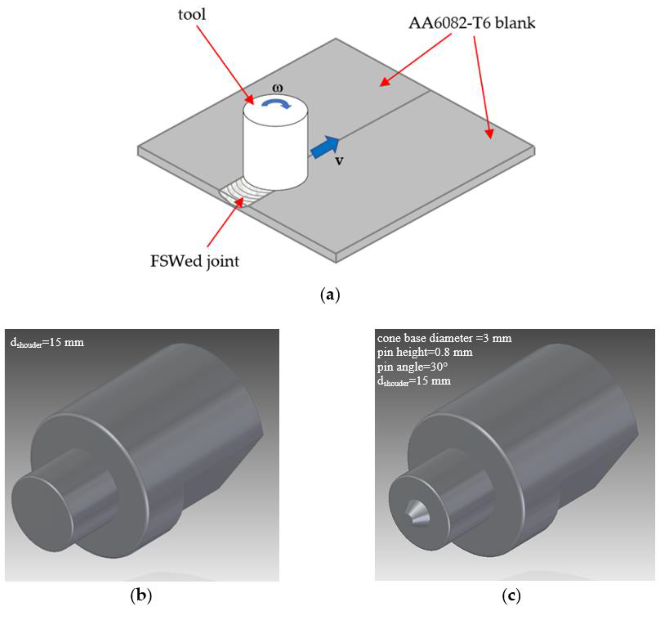
The material used was AA6082-T6 aluminum alloy, supplied in form of 1.0 mm thick sheet. Butt joints were obtained by friction stir welding (Figure 1a) carried out on a computer numerical control machining center. The blanks, 180 mm in length and 80 mm in width, were joined with the joint line perpendicular to the rolling direction. The plunging speed, plunging and the rotational speed (ω) were equal to 1.5 mm/min, 0.1 mm and 1500 rpm, respectively. The rotational speed and welding speed (v) were kept constant during the welding stage and equal to 1500 rpm and 60 mm/min, respectively, with an angle of 2°. As far as the tool configuration is concerned, the authors studied FSW of thin sheets using both pinless tool (Figure 1b) and pin tool (Figure 1c), showing that thin sheets can be successfully welded using the pinless tool [8]. Owing to the lack of the stirring action produced by the pin, heat is generated by the frictional forces arising at the tool shoulder—workpiece interface during plunging and welding stages. Figure 2a shows the effect of tool geometry on the nominal stress vs. nominal strain curves: FSWed joints obtained using the pinless tool configuration are characterized by ultimate tensile strength (UTS) and ultimate elongation (UE) values higher than those given by the pin tool one. For sake of comparison, Figure 2b shows the stress-strain curve of the parent material. By considering the results of tensile tests, FSWed blanks were manufactured using the pinless tool, with a shoulder diameter (dshoulder) of 15 mm.
Since 6xxx aluminum alloy series show a time-dependent mechanical behavior after friction stir welding, as shown by Hossfeld [24], the joints in AA6082 alloy were subjected to water jet cutting to obtain samples for the experimental tests and immediately frozen in order to avoid the natural ageing process. Considering the material handling and sample setting on the tooling for the experimental tests, the time interval during which AA6082 alloy can undergo natural aging was about 90 min.
2.2. Hemispherical Punch Tests
In order to evaluate the high-speed deformation behavior of FSWed blanks, hemispherical punch tests were carried out using the direct tension-compression Split Hopkinson Bar (SHB) shown in Figure 3. The SHB system is made up of three 17-4 PH bars, each with the diameter of 18 mm. The length of the pre-stressed bar, input bar and output bar are 3000 mm, 7500 mm and 4000 mm, respectively [25]. It consists of a die, a tightening screw, a blank holder with drawbead, a hemispherical punch and a spacer (Figure 4). Figure 5 shows the equipment installed on the Split Hopkinson Bar. In order to avoid significant bending of the output bar, a support was used to stand the relatively high weight of the equipment. Disk-shaped samples, with a diameter of 50 mm, were obtained by waterjet cutting from the FSWed blanks; the cutting process was performed by assuring that the welding line was coincident with the disk diameter (Figure 6). Samples were placed into the die with the top surface of the joint, that is, the side in touch with shoulder during FSW, opposed to the hemispherical punch surface. Friction was reduced by lubricating the hemispherical punch using a polytetrafluoroethylene foil with diameter smaller than the punch one to prevent the foil wrinkling. The punch speed was kept constant during testing and equal to 4500 mm/s. Different punch stroke values were imposed using the spacer. For each process condition, experimental trials were repeated at least three times.
The high-speed deformation behavior of FSWed joints was compared to the one under quasi-static condition. To this purpose, the hemispherical punch test was also performed using a servo-hydraulic testing machine (MTS Systems Corporation, Eden Prairie, MN, USA) equipped with a 20 kN load cell. Tests were carried out under displacement control, at the punch speed equal to 0.1 mm/s, with the same equipment, and sample geometry and positioning used in the high-speed tests.
2.3. Scanning Electron Microscopy
A scanning electron microscope (SEM) (Philips, Amsterdam, The Netherlands), in backscattered electron mode, was used to obtain high magnification three-dimensional topography of fractured surfaces of deformed FSWed disk-shaped samples.
3. Results and Discussion
The high-speed hemispherical punch tests were performed by acquiring input, reflected and transmitted waves. To this purpose, Figure 7 shows typical wave signals gained during the dynamic test. The input and reflected wave signals were acquired by the strain gauge on the input bar. The transmitted wave, recorded by the strain gauge on the output bar, smoothly rises until a sudden increase takes place; the former part corresponds to the phase during which the punch gradually deforms the FSWed disk-shaped sample; the latter is due to the impact between the spacer and the tightening screwed cap. Even though pressure waves may continue to travel back and forth along the bars, the further deformations of the FSWed sample are prevented by the spacer.
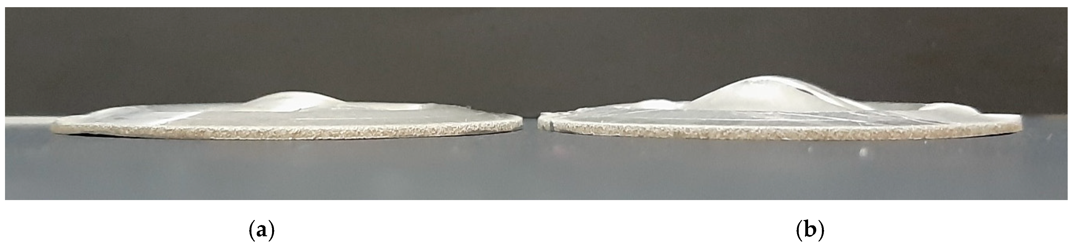
A series of high-speed deformation tests was carried out at different punch strokes, obtained by adjusting the spacer shown in Figure 4 and Figure 5, until failure of the disk-shaped FSWed samples under the biaxial balanced stretching condition. To this purpose, Figure 8 shows samples deformed at the onset of necking (Figure 8a) and to failure (Figure 8b); the dome height at which necking begins was about 4 mm whilst the FSWed blank fails at the dome height of about 4.5 mm.
The hemispherical punch tests were also carried out under quasi-static condition, with a punch speed equal to 0.1 mm/s, by means of the servo-hydraulic testing machine. Moreover, in this condition, samples were deformed at the onset of necking (Figure 9a) and to failure (Figure 9b). As far as the punch load vs. punch stroke curve is concerned, the results given by three test repetitions prove the excellent repeatability of the test (Figure 10a). The dome height at the onset of necking, corresponding to the punch stroke at the peak value of the load-stroke curve (Figure 10b), was equal to 3.3 mm, whilst the dome height to failure was about 3.5 mm. Figure 10b also shows the load vs. stroke curve evaluated by testing FSWed joints obtained using the pin tool shown in Figure 1c. The values of dome height at the onset of necking and to failure, equal to about 3.1 mm and 3.25 mm, respectively, confirm, as already shown in Figure 2 in terms of mechanical properties, that the pinless tool allows to obtain thin sheet FSWed joints with higher performances than those realized with the pin tool.
By comparing the dome height values at the onset of necking measured by the hemispherical punch test under dynamic and quasi-static conditions, it clearly appears that the former is higher than the latter. Such evidence was confirmed by the dome top surface of FSWed samples obtained in the high-speed deformation with a punch stroke of 4 mm (Figure 11a,b), which exhibits the onset of necking along the welding line whilst the top surface in the low-speed deformation, at the same dome height, shows a large fracture along the welding line (Figure 11c,d).
The effect of the loading rate on the deformation behavior of FSWed blanks in AA6082-T6 is consistent with the one observed by the authors in the parent material, both in the uniaxial and balanced biaxial stretching conditions [23]. To this purpose, Table 1 summarizes the properties, both under dynamic and quasi-static loading conditions, evaluated on the parent material and friction stir welded joints. The parent material in the T6 temper state exhibits a decrease in both strain to failure and dome height from dynamic to quasi-static loading conditions whilst the ultimate tensile strength and strain hardening exponent (n) do not show any significant discrepancy in the two different loading conditions. A similar behavior is exhibited by welded joints, even though the mechanical properties and formability are lower than those of the parent material.
In order to understand the mechanisms leading to the increase in the dome height to failure as the FSWed blanks are deformed under dynamic loading condition with respect to the quasi-static one, SEM analysis of the fractured surfaces was carried out (Figure 12). Irrespective of the punch speed, failure occurs along the welding line (Figure 12a,b) consistently with the onset of necking observed on the top surface of the FSWed disk-shaped samples shown in Figure 11. Figure 12b also shows, under quasi-static condition, the occurrence secondary cracks, growing perpendicularly to the welding line, which were not visible at the onset of failure (Figure 11c,d). Furthermore, due to the impulsive loading induced by the SHB, deformation is localized in a relatively small region whilst a more uniform strain distribution occurs in the dome region under quasi-static condition. This behavior is also evidenced by the different heights of asperities generated by the combined rotational and welding motions of the pinless tool during the FSW process, after the hemispherical punch test; as a matter of fact, in the top surface of the dome obtained under dynamic loading condition, the asperities are higher than those observed on the sample deformed under quasi-static condition (Figure 12c,d).
As far as fracture mechanisms are concerned, it is known that the dimple fracture and shear fracture are two major fracture mechanisms for ductile materials [26]. The fractured surface of the FSWed sample deformed at punch speed of 4500 mm/s shows a large area of ductile fracture, characterized by bumps and hollows, and the remaining one of shear fracture (Figure 12e). SEM image shows the typical mechanisms of ductile fracture, involving nucleation, growth and coalescence of micro-voids, with a large number of voids and dimples. Micro-voids nucleate giving priority to precipitates and then become larger with increasing strain owing to the rise in the punch displacement. Finally, micro-void coalescence leads to many micro-cracks. As they join together and enlarge to the area close to the sample surface, shear fracture occurs. The SEM micrograph of FSWed sample tested at punch speed of 0.1 mm/s (Figure 12f) shows dimples characterized by different sizes and heights in the fractured surface; furthermore, large dimples, which accelerate the dimple fracture, are evident. The localization of shear bands which causes the shear fracture can be also observed.
4. Conclusions
In the present work, the high-speed deformation behavior of friction stir-welded thin sheets in AA6082-T6 aluminum alloy, under balanced biaxial stretching condition, was investigated. To this purpose, hemispherical punch tests were carried out using a direct tension-compression Split Hopkinson Bar, with a punch speed of 4500 mm/s, on FSWed blanks obtained using a pinless tool. Tests were performed at different punch stroke values until fracture of the disk-shaped sample. The main results can be summarized as follows:
(1) The dome height at the onset necking under dynamic condition was about 4.0 mm, whilst failure occurred along the welding line at a dome height of about 4.5 mm. Fractographic images reveal that deformation is localized in the fracture zone.
(2) FSWed samples deformed under quasi-static loading condition are characterized by a dome height at the onset of necking of 3.3 mm, significantly lower than that measured under dynamic condition. Fracture takes place along the welding line, and deformation is more uniformly distributed in the dome region.
(3) In the high-speed deformation, the fractured surface of the FSWed sample shows a large area of ductile fracture, characterized by bumps and hollows, and the remaining one of shear fracture. As far as low-speed deformation is concerned, the fractured surface is characterized by large dimples, which accelerate the dimple fracture. The low-speed deformation also leads to the localization of shear bands which causes the shear fracture.
Author Contributions
Conceptualization, A.F. and M.S.; data curation, M.S.; formal analysis, A.F. and M.S.; investigation, M.S.; methodology, A.F. and M.S.; project administration, A.F.; supervision, A.F.; writing—original draft, M.S.; writing—review and editing, A.F. All authors have read and agreed to the published version of the manuscript.
Funding
This research received no external funding.
Acknowledgments
Edoardo Mancini, Massimiliano Pieralisi, Luigi Gobbi and Daniele Ciccarelli are acknowledged for their contribution in carrying out the experimental tests.
Conflicts of Interest
The authors declare no conflict of interest.
References
- Merklein, M.; Johannes, M.; Lechner, M.; Kuppert, A. A review on tailored blanks—Production, applications and evaluation. J. Mater. Process. Technol. 2014, 214, 151–164. [Google Scholar] [CrossRef]
- Devarasiddappa, D. Automotive Applications of Welding Technology—A Study. Int. J. Mod. Eng. Res. 2014, 4, 13–19. [Google Scholar]
- Mishra, R.S.; Ma, Z.Y. Friction Stir Welding and Processing II Article in Materials Science and Engineering R Reports September 2005. Mater. Sci. Eng. R 2014, 50, 1–78. [Google Scholar] [CrossRef]
- Loureiro, A.; Leal, R.M.; Leitão, C.; Rodrigues, D.M.; Vilaça, P. Friction stir welding of automotive aluminium alloys. Weld. World 2007, 51, 433–440. [Google Scholar]
- Bruni, C.; Buffa, G.; Fratini, L.; Simoncini, M. Friction stir welding of magnesium alloys under different process parameters. In Proceedings of the Materials Science Forum, Berlin, Germany, 25–29 August 2010; Volume 638–642, pp. 3954–3959. [Google Scholar]
- Forcellese, A.; Simoncini, M.; Casalino, G. Influence of process parameters on the vertical forces generated during friction stir welding of AA6082-T6 and on the mechanical properties of the joints. Metals 2017, 7, 350. [Google Scholar] [CrossRef] [Green Version]
- Leal, R.M.; Leitão, C.; Loureiro, A.; Rodrigues, D.M.; Vilaça, P. Material flow in heterogeneous friction stir welding of thin aluminium sheets: Effect of shoulder geometry. Mater. Sci. Eng. A 2008, 498, 384–391. [Google Scholar] [CrossRef] [Green Version]
- Forcellese, A.; Simoncini, M. Plastic flow behaviour and formability of friction stir welded joints in AZ31 thin sheets obtained using the “pinless” tool configuration. Mater. Des. 2012, 36, 123–129. [Google Scholar] [CrossRef]
- Haghshenas, M.; Gerlich, A.P. Joining of automotive sheet materials by friction-based welding methods: A review. Eng. Sci. Technol. Int. J. 2018, 21, 130–148. [Google Scholar] [CrossRef]
- Bevilacqua, M.; Ciarapica, F.E.; Forcellese, A.; Simoncini, M. Comparison among the environmental impact of solid state and fusion welding processes in joining an aluminium alloy. Proc. Inst. Mech. Eng. B J. Eng. Manuf. 2019, 1–17. [Google Scholar] [CrossRef]
- Bevilacqua, M.; Ciarapica, F.E.; D’Orazio, A.; Forcellese, A.; Simoncini, M. Sustainability Analysis of Friction Stir Welding of AA5754 Sheets. Procedia CIRP 2017, 62, 529–534. [Google Scholar] [CrossRef]
- Sato, Y.S.; Sugiura, Y.; Shoji, Y.; Park, S.H.C.; Kokawa, H.; Ikeda, K. Post-weld formability of friction stir welded Al alloy 5052. Mater. Sci. Eng. A 2004, 369, 138–143. [Google Scholar] [CrossRef]
- Zadpoor, A.A.; Sinke, J.; Benedictus, R. Finite element modeling and failure prediction of friction stir welded blanks. Mater. Des. 2009, 30, 1423–1434. [Google Scholar] [CrossRef]
- Jia, Y.; Lin, S.; Liu, J.; Qin, Y.; Wang, K. The Influence of Pre- and Post-Heat Treatment on Mechanical Properties and Microstructures in Friction Stir Welding of Dissimilar Age-Hardenable Aluminum Alloys. Metals 2019, 9, 1162. [Google Scholar] [CrossRef] [Green Version]
- Cabibbo, M.; Forcellese, A.; Simoncini, M.; Pieralisi, M.; Ciccarelli, D. Effect of welding motion and pre-/post-annealing of friction stir welded AA5754 joints. Mater. Des. 2016, 93, 146–159. [Google Scholar] [CrossRef]
- Casalino, G.; El Mehtedi, M.; Forcellese, A.; Simoncini, M. Effect of cold rolling on the mechanical properties and formability of FSWed sheets in AA5754-H114. Metals 2018, 8, 223. [Google Scholar] [CrossRef] [Green Version]
- Peng, G.; Yan, Q.; Hu, J.; Chen, P.; Chen, Z.; Zhang, T. Effect of forced air cooling on the microstructures, Tensile strength, and Hardness distribution of dissimilar friction stir welded AA5A06-AA6061 Joints. Metals 2019, 9, 304. [Google Scholar] [CrossRef] [Green Version]
- Cisko, A.R.; Jordon, J.B.; Avery, D.Z.; Liu, T.; Brewer, L.N.; Allison, P.G.; Carino, R.L.; Hammi, Y.; Rushing, T.W.; Garcia, L. Experiments and modeling of fatigue behavior of friction stir welded aluminum lithium alloy. Metals 2019, 9, 293. [Google Scholar] [CrossRef] [Green Version]
- Baratzadeh, F.; Tay, Y.Y.; Patil, S.; Lankarani, H.M. An experimental and numerical investigation into the dynamic crash testing of vehicle bumper fabricated using friction stir welding and gas metal arc welding. Int. J. Crashworthiness 2014, 19, 371–384. [Google Scholar] [CrossRef]
- Chen, X.; Peng, Y.; Peng, S.; Yao, S.; Chen, C.; Xu, P. Flow and fracture behavior of aluminum alloy 6082-T6 at different tensile strain rates and triaxialities. PLoS ONE 2017, 12, e0181983. [Google Scholar] [CrossRef] [Green Version]
- Djapic Oosterkamp, L.; Ivankovic, A.; Venizelos, G. High strain rate properties of selected aluminium alloys. Mater. Sci. Eng. A 2000, 278, 225–235. [Google Scholar] [CrossRef]
- Yokoyama, T.; Nakai, K.; Katoh, K. High Strain-rate Compressive Response of Friction Stir Welded AA6061-T6 Joints. J. JSEM 2010, 10, 168–173. [Google Scholar]
- Sasso, M.; Mancini, E.; Chiappini, G.; Simoncini, M.; Forcellese, A. Adapted Nakazima test to evaluate dynamic effect on strain distribution and dome height in balanced biaxial stretching condition. Int. J. Mech. Sci. 2018, 148, 50–63. [Google Scholar] [CrossRef]
- Hossfeld, M. Time-dependency of mechanical properties and component behavior after friction stir welding. Int. J. Adv. Manuf. Technol. 2019, 102, 2297–2305. [Google Scholar] [CrossRef]
- Mancini, E.; Sasso, M.; Rossi, M.; Chiappini, G.; Newaz, G.; Amodio, D. Design of an innovative system for wave generation in direct tension–compression Split Hopkinson Bar. J Dynam Behav Mater. 2015, 1, 201–213. [Google Scholar] [CrossRef] [Green Version]
- Komori, K. Microscopic ductile fracture phenomena. In Ductile Fracture in Metal Forming: Modeling and Simulation; Elsevier Inc.: Amsterdam, The Netherlands, 2019; pp. 95–129. [Google Scholar] [CrossRef]
Figure 1.
(a) Scheme of friction stir welding process of AA6082-T6 blanks, (b) pinless tool and (c) pin tool.
Figure 1.
(a) Scheme of friction stir welding process of AA6082-T6 blanks, (b) pinless tool and (c) pin tool.

Figure 2.
Typical flow curves of: (a) friction stir welded AA6082-T6 thin sheets using different tool configurations (rotational speed: 1500 rpm; welding speed: 60 mm/min) and (b) parent material.
Figure 2.
Typical flow curves of: (a) friction stir welded AA6082-T6 thin sheets using different tool configurations (rotational speed: 1500 rpm; welding speed: 60 mm/min) and (b) parent material.
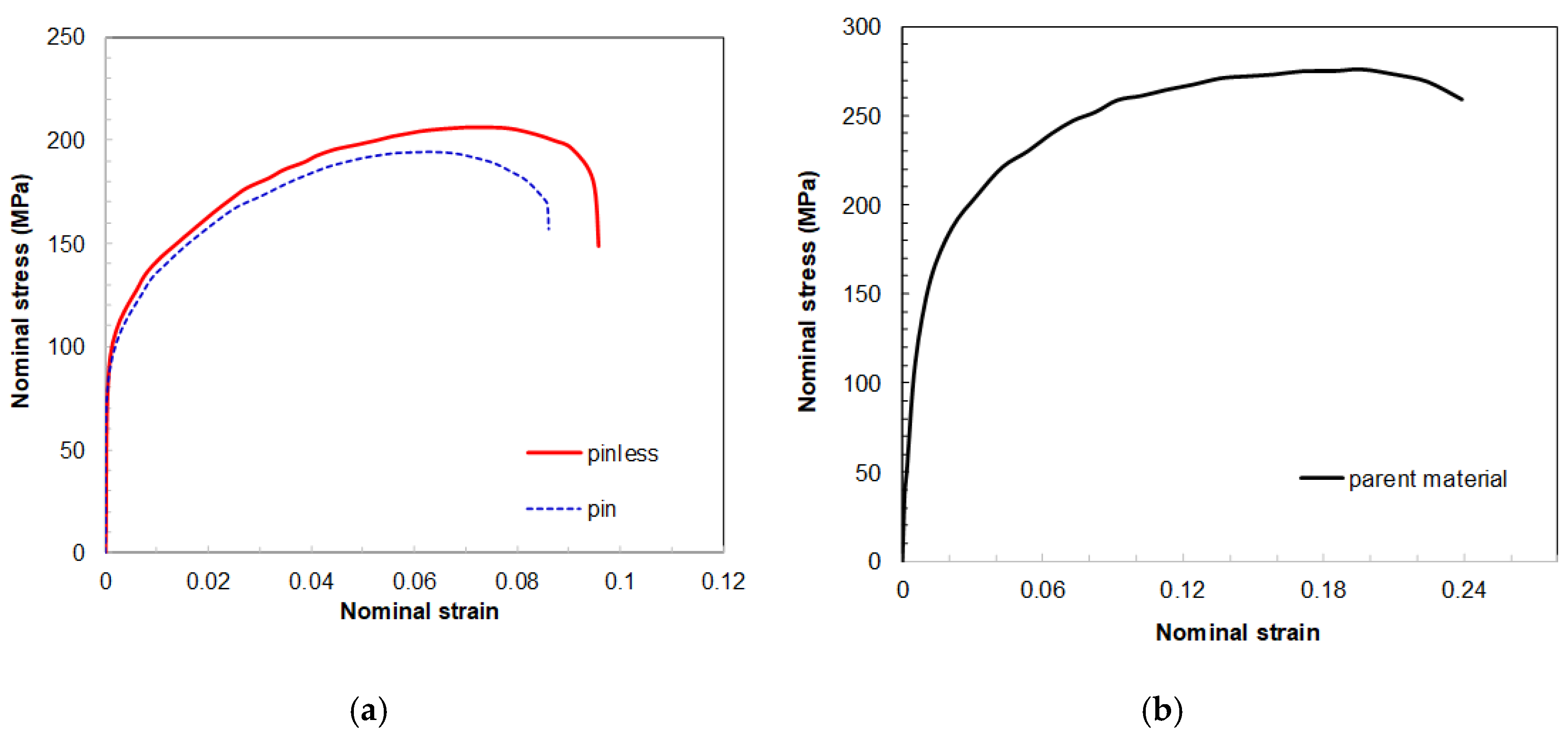
Figure 3.
Direct tension-compression Split Hopkinson Bar used for high-speed deformation tests [25].
Figure 3.
Direct tension-compression Split Hopkinson Bar used for high-speed deformation tests [25].

Figure 4.
Equipment developed for the hemispherical punch test.

Figure 5.
Equipment used for hemispherical punch test installed on the Split Hopkinson Bar.

Figure 6.
FSWed disk-shaped sample used in the hemispherical punch test.
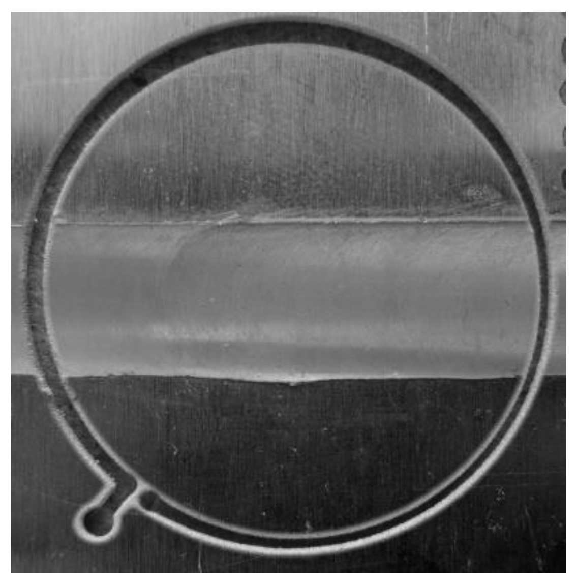
Figure 7.
Input, reflected and transmitted wave signals acquired the high-speed hemispherical punch test (punch stroke: 3.2 mm).
Figure 7.
Input, reflected and transmitted wave signals acquired the high-speed hemispherical punch test (punch stroke: 3.2 mm).
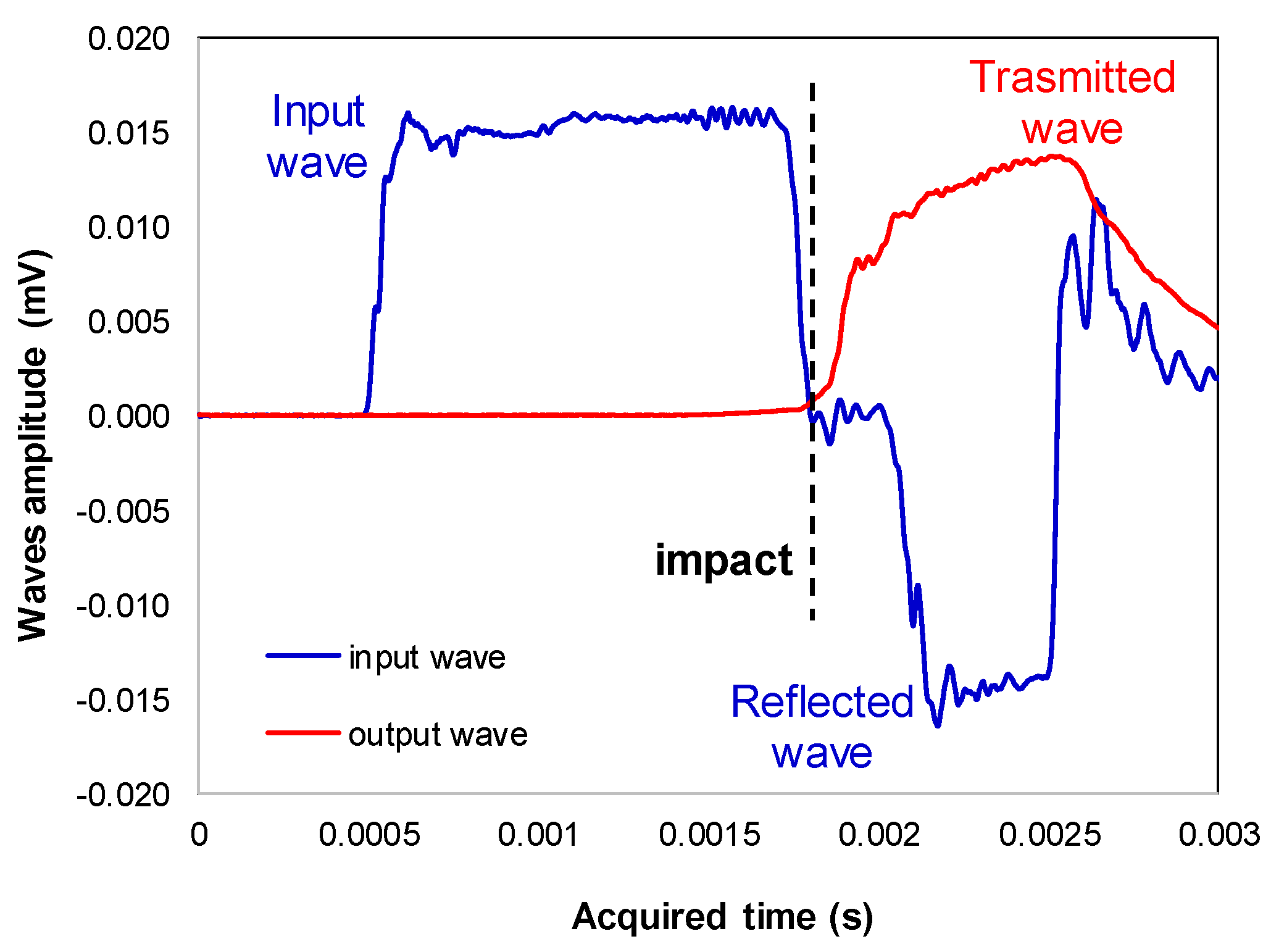
Figure 8.
FSWed samples, tested at punch speed of 4500 mm/s, with different dome heights: (a) onset of necking (dome height of 4.0 mm), and (b) failure region (dome height of 4.5 mm).
Figure 8.
FSWed samples, tested at punch speed of 4500 mm/s, with different dome heights: (a) onset of necking (dome height of 4.0 mm), and (b) failure region (dome height of 4.5 mm).

Figure 9.
FSWed samples, tested at a punch speed of 0.1 mm/s, with different dome heights: (a) onset of necking (dome height of 3.3 mm) and (b) failure region (dome height of 3.8 mm).
Figure 9.
FSWed samples, tested at a punch speed of 0.1 mm/s, with different dome heights: (a) onset of necking (dome height of 3.3 mm) and (b) failure region (dome height of 3.8 mm).

Figure 10.
Punch load vs. punch stroke of FSWed disk-shaped samples obtained by hemispherical punch test performed under quasi-static condition: (a) different repetitions using the pinless tool and (b) comparison between the pinless and pin tools.
Figure 10.
Punch load vs. punch stroke of FSWed disk-shaped samples obtained by hemispherical punch test performed under quasi-static condition: (a) different repetitions using the pinless tool and (b) comparison between the pinless and pin tools.
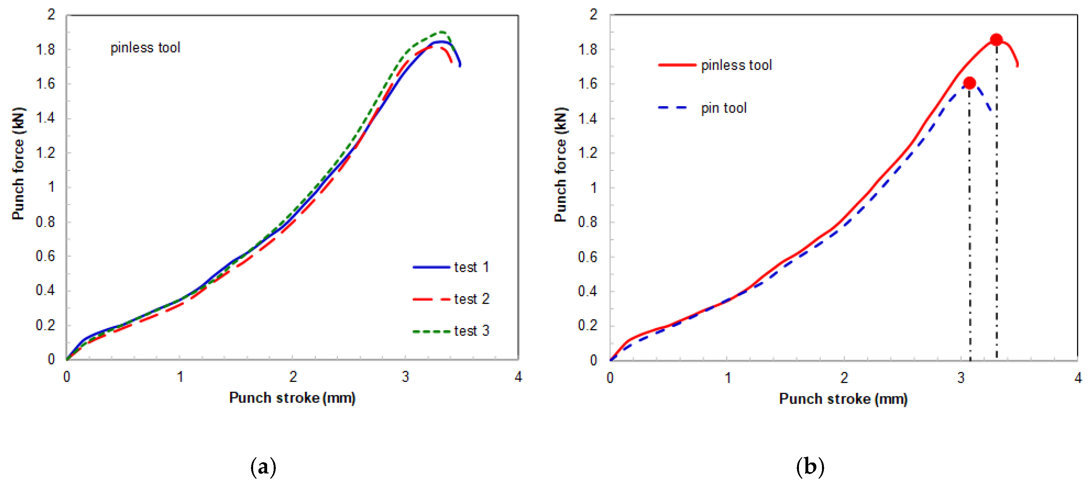
Figure 11.
Top surfaces of FSWed disk-shaped samples, at different magnifications obtained by SEM, tested by the hemispherical punch test at a punch stroke of 4 mm under: (a,b) dynamic loading and (c,d) quasi-static loading.
Figure 11.
Top surfaces of FSWed disk-shaped samples, at different magnifications obtained by SEM, tested by the hemispherical punch test at a punch stroke of 4 mm under: (a,b) dynamic loading and (c,d) quasi-static loading.

Figure 12.
SEM micrographs, at different magnifications, obtained on fractured FSWed samples: (a,c,e) high-speed deformation (4500 mm/s), and (b,d,f) low-speed deformation (0.1 mm/s).
Figure 12.
SEM micrographs, at different magnifications, obtained on fractured FSWed samples: (a,c,e) high-speed deformation (4500 mm/s), and (b,d,f) low-speed deformation (0.1 mm/s).


Table 1.
Effect of loading conditions on mechanical properties and formability of parent material and FSWed joints in AA6082-T6 alloy using pinless tool (data on parent material taken from [23]).
Table 1.
Effect of loading conditions on mechanical properties and formability of parent material and FSWed joints in AA6082-T6 alloy using pinless tool (data on parent material taken from [23]).
| Properties | Parent Material | FSWed Joint (Pinless) | ||
|---|---|---|---|---|
| Quasi-Static | Dynamic | Quasi-Static | Dynamic | |
| UTS (MPa) | 275.9 | 272.4 | 206.3 | 210.5 |
| UE | 0.24 | 0.35 | 0.09 | 0.14 |
| n | 0.217 | 0.217 | 0.229 | 0.226 |
| LDH (mm) | 8.09 | 8.84 | 3.3 | 4 |
© 2019 by the authors. Licensee MDPI, Basel, Switzerland. This article is an open access article distributed under the terms and conditions of the Creative Commons Attribution (CC BY) license (http://creativecommons.org/licenses/by/4.0/).
Share and Cite
MDPI and ACS Style
Forcellese, A.; Simoncini, M. High-Speed Deformation of Pinless FSWed Thin Sheets in AA6082 Alloy. Metals 2020, 10, 15. https://doi.org/10.3390/met10010015
AMA Style
Forcellese A, Simoncini M. High-Speed Deformation of Pinless FSWed Thin Sheets in AA6082 Alloy. Metals. 2020; 10(1):15. https://doi.org/10.3390/met10010015
Chicago/Turabian StyleForcellese, Archimede, and Michela Simoncini. 2020. "High-Speed Deformation of Pinless FSWed Thin Sheets in AA6082 Alloy" Metals 10, no. 1: 15. https://doi.org/10.3390/met10010015
Note that from the first issue of 2016, this journal uses article numbers instead of page numbers. See further details here.