Research of Tribological Properties of 34CrNiMo6 Steel in the Production of a Newly Designed Self-Equalizing Thrust Bearing


1
Faculty of Mechanical Engineering, West Bohemia University in Pilsen, Univerzitni 22, 301 00 Pilsen, Czech Republic
2
Faculty of Manufacturing Technologies with the Seat in Presov, Technical University of Kosice, Sturova 31, 080 01 Presov, Slovakia
3
Faculty of Technology, UTB Tomas Bata University in Zlin, Vavreckova 275, 760 01 Zlin, Czech Republic
*
Author to whom correspondence should be addressed.
Metals 2020, 10(1), 84; https://doi.org/10.3390/met10010084
Submission received: 30 November 2019
/
Revised: 23 December 2019
/
Accepted: 28 December 2019
/
Published: 3 January 2020
(This article belongs to the Special Issue Failure Mechanisms in Alloys)
Abstract
:There are many cases when in large power equipment (such as a turbine or compressor) asymmetrically loading on bearings due to thermal deformations, production inaccuracies, or simple deflection of the shaft occurs. This asymmetrically loading means misalignment of rotor against stator in angle more than several tenths of a degree and it has an influence on a journal and thrust bearings. Over the last few years, thanks to increasingly precise manufacturing, solutions that can eliminate this phenomenon have been revealed. In the case of the thrust bearing, it is a system of very precise manufactured levers, which are in close contact each to other, so they have to be not only properly designed from the geometrical point of view but the important role plays a quality of the functional surfaces of these levers. The article deals with the surface treatment effect on tribological properties of 34CrNiMo6 steel used for the production of bearing levers, which are the critical parts of a newly developing self-equalizing thrust bearing. The samples with cylindrical and plate shapes were produced from 34CrNiMo6 steel as representatives of the most suitable geometries for contact surfaces. All samples were heat-treated. The surfaces of some samples were treated by electroless nickel plating or nitriding, some of the samples were treated by tumbling. Gradually, the surface roughness, microhardness, metallographic analysis and the influence of selected types of surface treatments on the wear for individual samples were evaluated within the research presented in the article. As the testing methods for evaluation of tribological properties were selected Pin-on-disc test and frequency tribological test. The results showed that the best tribological properties achieved samples treated by electroless nickel plating compared with the nitrided or only heat-treated samples.
1. Introduction
Today, the energy industry must deal with two interrelated trends. The first trend is the ever-increasing demand for electricity worldwide and the second trend is the continuously the rising price of power. This situation can be solved in two ways, either to build new installations (or whole power plants) with greater efficiency or to improve (increase efficiency) existing installations [1]. One way or another, the worldwide annual need for rotating machines (e.g., turbines, compressors, generators, turbo-gearboxes, etc.), which is already now in several thousands, will grow [2].
In order to manufacturers of rotary machines flexibly respond to the growing demand for high-performance machines with high efficiency, designed for specific applications in specific operating conditions, and to maintain their market share, they must use top quality components. Undoubtedly, one of the key parts of the power machine are bearings that make a significant contribution to the overall power loss of the machine. It is a reason, why the manufacturers of such rotary machines place the highest demands on the bearings [3].
In machinery, to absorb the axial forces, the hydrodynamic thrust bearings are used, especially where the use of antifriction bearings is unsuitable in terms of dimensional limits, service life, high load, or difficult access during assembly [4]. When applied correctly, the plain bearing saves weight, space, bears more load, requires less maintenance and resists vibrations better than a roller bearing. On the other hand, an incorrect application can cause the relative surface interaction of the sliding bearing components that can lead to material loss at the points of contact, i.e., wear. Depending on the type of contact and movement of the bodies, wear is realized by various mechanisms, e.g., adhesive, abrasive, erosive or cavitation [5,6]. Wear resistance is a critical property directly affecting the life of bearings and surface properties. Therefore, knowledge of the mechanical and tribological properties of a material makes it possible to predict to a large extent its surface resistance to various forms of wear [7].
2. State of the Art
It often happens in real practice, especially in large rotary machines, that between stator and rotor necessary parallelism of active bearing and thrust collar is not guaranteed, what results in reduced bearing capacity. This misalignment can be caused by many factors (thermal dilatation, shaft misalignment, “inaccuracy” in production, etc.), the magnitude of which is dependent on the peripheral speed and the load [8]. The phenomenon of deflection of the shaft collar from the bearing axis during operation (up to several tenths of a degree) has been known for several decades, but at present, the only solution, that is capable to equalize misalignment between shaft and bearing axis, is the solution using the system of levers inside so-called a self-equalizing bearing, presented in Figure 1 [9,10].
Due to the different mergers between global bearing manufacturers in recent years, there are currently only three major global suppliers that produce this type of bearings as standard—i.e., not as a special project. They are Waukesha (USA, Scotland), Kingsbury (USA, GB, Germany), Miba (John Crane) (USA, Germany). Each of these manufacturers uses, to a greater or lesser degree, a different design and manufacturing technology.
At least two elements are required for the slide bearing—the bearing itself and the rotor collar. The sliding bearing contains segments to which lubricating oil is supplied. Each segment is a separate carrier part of the bearing. The bearing surfaces (both bearings and shaft collars) are completely separated by an oil film with a thickness of approx. 20–40 µm. The oil film avoids the risk of contact and therefore abrasion of the bearing surfaces [11].
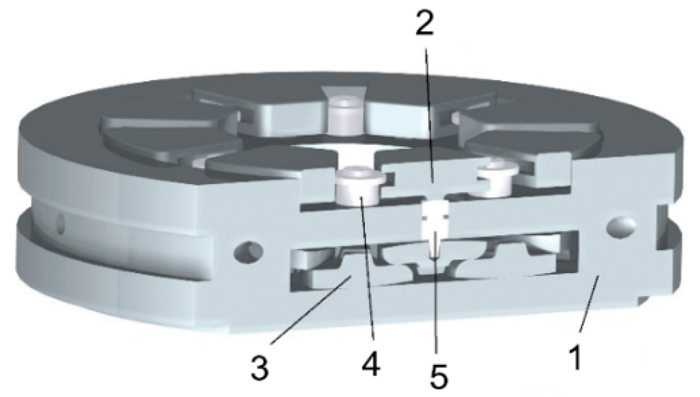
Self-equalizing thrust pad bearings consist of the following basic parts (Figure 2):
(1) bearing body/housing;
(2) thrust pad;
(3) self-equalizing element (lever);
(4) nozzle;
(5) floating pressure element.
The most important (and critical) part of the axial self-aligning bearing assembly is the equalizing element—the lever. For every thrust, the pad is necessary to use 2 levers. It means that for example at 18 pads bearing is necessary to use 36 levers.
The aim of the set of levers is to distribute the load evenly over the entire circumference of the bearing. The evenly distributed load is then transferred to the bearing housing and subsequently to the machine frame. The lever system must be designed and manufactured so that it is capable of transferring the pressure/force exerted on the lower part of the bearing to the upper part of the bearing [12], i.e., that the thrust pads are always in contact with the shaft collar. (Figure 3).
Ideally, the forces acting on the lever should be the same everywhere, but because of the passive resistance and the inappropriate geometry of the levers, these forces are different. In the case of an incorrectly designed bearing construction, it occurs to the undesirable wear of levers [13,14], as shown in Figure 4.
The biggest problem is often incorrect machining of the geometrical/micro-geometrical shape of the functional surfaces [15]. For example, if the machining technology or strategy is incorrectly selected, the surfaces may be undulating and thus do not meet the theoretical requirements for an ideal wedge surface, respectively for an ideally designed shape. The functional surfaces can also be deformed by thermal loading of the components [16].
The roughness of the functional sliding bearing surfaces plays an important role. Too much roughness can cause rapid wear, damage or destruction of the functional surfaces if the lubrication is insufficient [17]. It is always better for the flow of medium if roughness on the sliding surface of slide bearings with white metal is low. (The white metal is a bearing metal, usually on a tin or lead basis, which is applied to the sliding surface of the bearing due to a certain “fuse” if the oil supply would fail or there would be some overload in the bearing and the oil film is broken. In this case, the bearing will be damaged and not the shaft that is many times more expensive). Regarding surface on levers (i.e., without white metal), low roughness in the range Ra 0.6–4.5 is secure (it doesn’t occur there to micro-welds, and either adhesive part of the wear is not significant) [18,19]. At high sliding speeds, the surface roughness can change the flow pattern of the medium from laminar to turbulent. A great influence on the bearing function has the choice of a suitable oil, which under the operating conditions of the sliding bearing should have such a viscosity so that a hydrodynamic wedge is created [19].
The material of the levers must, therefore, possess sufficient mechanical and tribological properties, taking into account also aspects of surface integrity. According to Pantazopoulos [20], if are known the loading conditions and the maximum (undetected) crack or minimum (detectable) crack size, specified that can be accurately measured by quality control, then also a minimum fracture resistance (toughness) of the material can be ascertained and the information can be used for material selection or during the design stage. Based on this approach, the wear and tribological properties of the material of newly developed self-equalizing bearing have been investigated with the goal to evaluate the quality of a contact surface and, already in the design stage, to judge the suitability of the material, including the selected types of its surface treatments, for production of this bearing and its implementation into a large power equipment.
There are several materials that can be used for this purpose, but one of the most commonly used in the production of bearings and which meets the required characteristics of a highly stressed functional component is DIN 34CrNiMo6 steel [21]. Based on the long-term experience of the bearing producers with this material, and based on the current studies, this steel was also selected as a material for the production of bearing prototype and for the study within this research.
It is one of heat-treated low-alloy steel with a high hardenability and strength, which contains nickel, chromium, and molybdenum. Moreover, the 34CrNiMo6 steel exhibits very good toughness properties with a Charpy V-notch at a very low temperature. In the actual production process, the typical heat treatment of this steel involves two stages, quenching and tempering. The 34CrNiMo6 steel can obtain high strength after quenching to a fully martensitic microstructure, while the ductility and toughness can be improved with tempering [22].
Popescu et al. [23] studied the effects of bulk tempering on the hardenability and temper-ability of 34CrNiMo6 steel. The experiment investigated the correlation between the hardness achieved after high tempering of products and their equivalent diameter and the heat and time parameters of tempering. Cochet et al. [24] investigated the heat-treatment parameters of the 34CrNiMo6 steel used for shackles. The results firstly provided a validation of the input data and the prediction of the phase volume fractions and the resulting hardness, which showed that the proposed approach could yield a very good representation of the material properties. The results showed that the heat-treatment method could significantly improve the mechanical properties by changing the nucleation rate and growth rate of austenite. Researchers Ge & Wang [25] studied the effect of the tempering temperature on the microstructure and mechanical properties of the 34CrNiMo6 steel during a tempering process. Low-cycle fatigue behaviour of 34CrNiMo6 high strength steel was investigated systematically under fully reversed strain-controlled conditions at room temperature by Branco [26]. Li et al. [27] found that the mechanical properties of the 34CrMo4 steel gas cylinders were significantly improved after hot drawing and flow forming plus a designed heat treatment, compared with the base material. The observations of microstructure features such as grain size, sub-grain boundaries, and residual strain support the increase in mechanical properties due to the proposed manufacturing process.
Maniee [28] carried out a comparative study of tribological and corrosion behaviour of plasma nitrided 34CrNiMo6 steel under hot and cold wall conditions. The wear test was performed by pin-on-disc method. The results showed that nitriding under hot wall condition at the same temperature provided slightly better tribological and corrosion properties in comparison with cold wall condition.
Microstructure and Tribological Properties of Laser Forming Repaired 34CrNiMo6 Steel were studied by Huang [29]. He also observed that the wear mechanism of laser forming repaired samples is abrasive wear; whereas that of the substrate is abrasive wear and fatigue wear.
Despite the fact that 34CrNiMo6 steel is used quite often in bearing production [30], there are not many studies that deal with its tribological properties in detail, and therefore, it was necessary to investigate whether this material could be used to design and to manufacture a new type of the self-equalizing bearing that would be able to operate a longer time, more safely and with higher efficiency compared to the existing bearings implemented into a high-power rotary machines (such as turbines or compressors). The study was performed as a part of extensive and long-term research that was divided into several stages: from the development of new geometry of self-equalizing bearing elements, through the investigating their kinematic, dynamic and tribological behaviour, up to final testing of the newly designed bearing prototype including its implementation into real operation.
The specific goal of investigation that is elaborated in this article was to study the tribological properties of the self-equalizing bearing elements produced from EN/DIN 34CrNiMo6 steel and to find the most suitable type of their functional surface with respect of technology of design. To find the optimum variant of contact surfaces from both geometry and wear rate (bearing life) points of views, the influence of selected types of surface treatment on the functional surface properties was also analysed. The obtained results will make it possible to predict a large extent the surface resistance of the material to various forms of wear and it can give an answer on the question if it is reasonable to manufacture the functional surfaces of the levers with low roughness in a higher cost or to produce them with higher roughness in less expensive cost.
3. Experimental Samples Design
3.1. Geometry of Samples
In addition to the quality of functional surfaces and some aspects of technology, as the most important criteria affecting the wear and contact behaviour of functional surfaces, the geometry of the levers had to be taken into account when designing samples for experimental investigation of the tribological properties of 34CrNiMo6 steel.
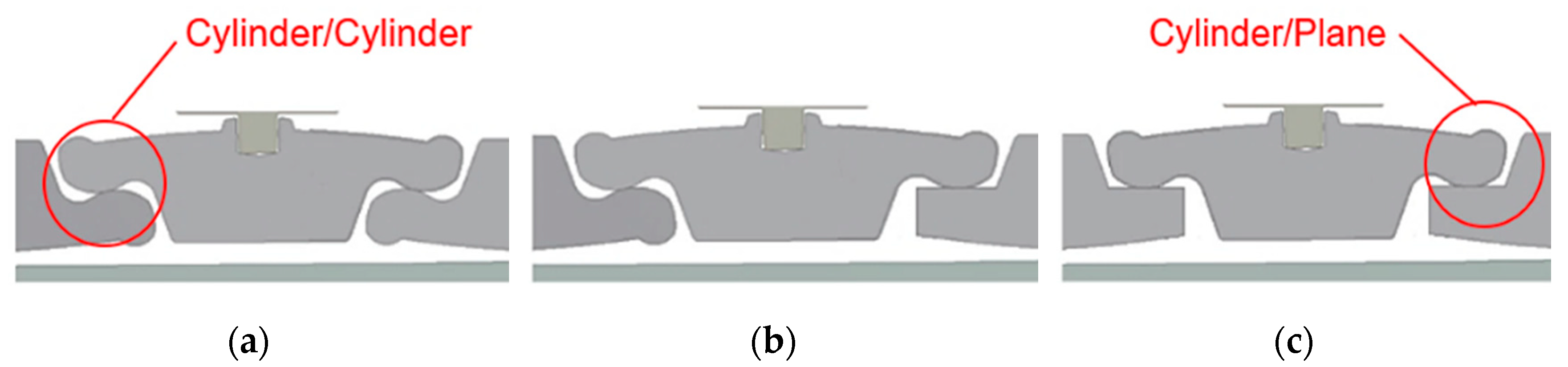
The geometry of the samples for experimental testing was built upon the research carried out in a previous stage (not presented in this paper), in which several variants of the lever geometry were gradually designed to create a functional model of the newly developed bearing. The kinematic functionality of all variants was verified by a simple test to measure the maximum misalignment of the levers. Based on the test results, which confirmed that the stiffness and overall kinematics of the rocker arm were found to be the best, the following lever shapes (profiles) and their contact were considered for subsequent tribological tests (Figure 5):
(1) “Cylinder/Cylinder” + “Cylinder/Cylinder”;
(2) “Cylinder/Cylinder” + “Cylinder/Plane”;
(3) “Cylinder/Plane” + “Cylinder/Plane”.
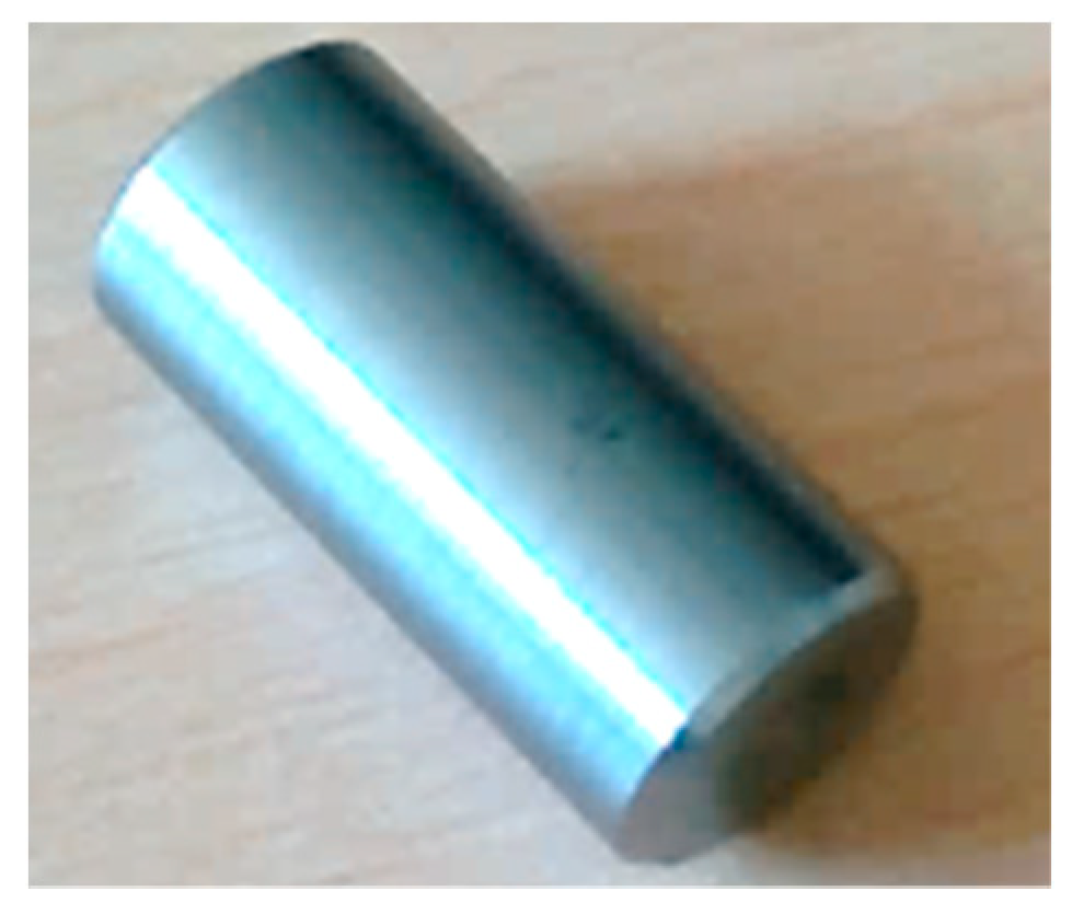
It would be unnecessary to produce complete levers for functional surface wear tests, and therefore, a simplified solution was adopted and the samples were designed in the form of a roller with the dimensions that corresponded to the rounded surface of the lever and in the form of a plate that represented the lever contact plane. Thus, in the experiment, the specimens had the shape of a 12 mm diameter cylinder and a 25 mm length, or a plate of 25 × 25 mm2, which correlated with the size of a lever for a reference bearing with 18 pads. An example of the cylindrical sample is in Figure 6.
3.2. Material of Samples
In view of the above, EN/DIN 34CrNiMo6 chromium-nickel-molybdenum heat-treated steel was chosen for levers and therefore also for the production of experimental samples. The practical use of chromium-nickel-molybdenum steel is based on the long-term operational reliability of the supplied products. It is a steel with high hardenability for highly stressed machine parts. In the treated state, it has a very favourable strength-to-yield ratio and a high toughness which hinders the propagation of fatigue cracks. The steel is therefore characterized by high fatigue limit values for alternating and combined stresses. It has high strength, high toughness and good hardenability [31].
Chemical composition of the 34CrNiMo6 steel is in Table 1.
3.3. Technological Conditions of Samples Production
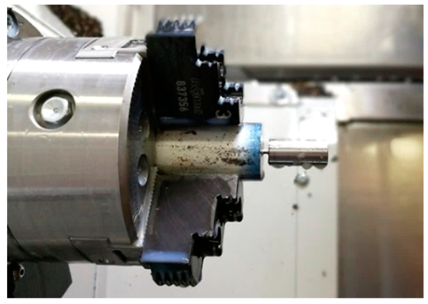
Since the selected sample shape is in the form of a cylinder, turning technology has been selected as the sample production technology. The surface roughness of the sample, which plays an important role in tribological tests, can be influenced by suitably selected machining conditions.
The machining was carried out on a machine EMCO MAXXTURN 25 (EMCO GmbH, Hallein, Austria). A bar with a diameter of 25 mm was selected as a semi-finished product. In the first step, the bar was roughened to ϕ D = 13 mm using a changeable insert ISCAR CCMT 09T304-SM (ISCAR Ltd., Haiger, Germany); consequently it was finished to a diameter of ϕ D = 12 mm using a changeable insert ISCAR DCMT 11T304-F3P (ISCAR Ltd., Haiger, Germany) and finally it was cut to a length of L = 25 mm. The machining process of sample production is presented in Figure 7.
The parameter that most influences the surface roughness during turning is a feed [32], therefore 5 different feeds per revolution f = 0.08; 0.12; 0.16; 0.2; 0.24 mm were chosen to monitor the wear of the cylinders. The next machining conditions were:
- cutting speed: vc = 120 m·min−1;
- cutting depth: ap = 0.5 mm;
- Coolant: Blasocut BC35 Kombi −5% + 95% water;
- feed per revolution: f = 0.08; 0.12; 0.16; 0.2; 0.24 mm.
All samples were subsequently treated after turning according to the recommendations for this material. The quenching was carried out in oil from a temperature of 830–860 °C and tempering during the temperatures ranged from 630 °C to 660 °C. The hardness of the base material was 330 HB.
At the same time, due to the load requirements of the levers, it was necessary to harden the functional surface of the levers. Based on existing research, scientific studies [33,34,35,36,37,38,39,40] and practical applications, the electroless nickel plating and nitriding were chosen as technologies for a surface reinforcement to enhance the tribological properties of the levers. These technologies can be used as a final surface treatment after finishing without additional grinding. Tumbling on an OTEC DF3 machine (OTEC GmbH, Straubenhardt, Germany) was also used as an intermediate between possible surface hardening for half of the samples (Samples No. 55-108). After several tests, the following tumbling parameters were selected.
| Tumbling type | Towed; |
| Rotor speed | 40 rpm; |
| Rotation bracket | 90 rpm; |
| Immersion depth | 420 mm; |
| Lift | Not used; |
| Medium | H4/400; |
| Clockwise tumbling time | 3 min; |
| Counterclockwise tumbling time | 3 min; |
| Total time | 6 min. |
3.4. Number of Experimental Samples
Each process is influenced by a number of specific factors that can be actively managed. At the output of these processes is then expected a certain result. Such a result is called a response. DoE (Design of Experiments) is a strategy in which the effects of several factors are studied at once by testing them at different levels. The task of DoE is then to find such a combination of factors that the process response is as accurate as possible. The response should then be monitored at several points in the experimental space. Tracking each point requires both time and cost, and this is important to realize. Therefore, it depends very much on how many points and how they are located in the experimental space [41].
With regard to the above-mentioned factors entering the process of production of experimental test samples (Section 3.3), it was not appropriate to choose a central composite plan, an application of which would require a very large number of samples, that would mean, besides the economic demands, a great time of experiment realization. Due to this reason, a “custom plan” was designed for the experiment. Orthogonality, rotation, etc., are also maintained in the design. According to this custom-designed plan, the production of testing cylinders was also planned, taking into account the following factors:
- (a)
- Load contact pairs “Cylinder/Cylinder = C/C” and “Cylinder/Plane = C/P”.
- (b)
- Parameter x1—feed per revolution: f1 = 0.08 mm; f2 = 0.12 mm; f3 = 0.16 mm; f4 = 0.2 mm; f5 = 0.24 mm.
- (c)
- Parameter x2—surface hardening: with or without tumbling, nitriding or electroless nickel plating.
A total of 108 cylinders with an assigned number and associated characteristics according to Table 2 were produced. In order to reduce the number of experiments, the plates were only ground and possibly surface reinforced. The wear was then monitored on a roller.
4. Preliminary Tests
4.1. Surface Roughness Investigation
After machining, it was measured the surface roughness of every cylindrical sample. The following parameters have been measured within the research of surface roughness: Ra—arithmetical average deviation from a mean line, Rz—ten-point height of irregularities, Rk—core roughness depth, Rpk—reduced peak height, Rvk—reduced valley depths, profile, Mr1—material portion 1 determined for the intersection line which separates the protruding peaks from the roughness core profile, Mr2—material portion 2 determined for the intersection line which separates the deep valleys from the roughness core profile, A1—Peak area and A2—Valley area.
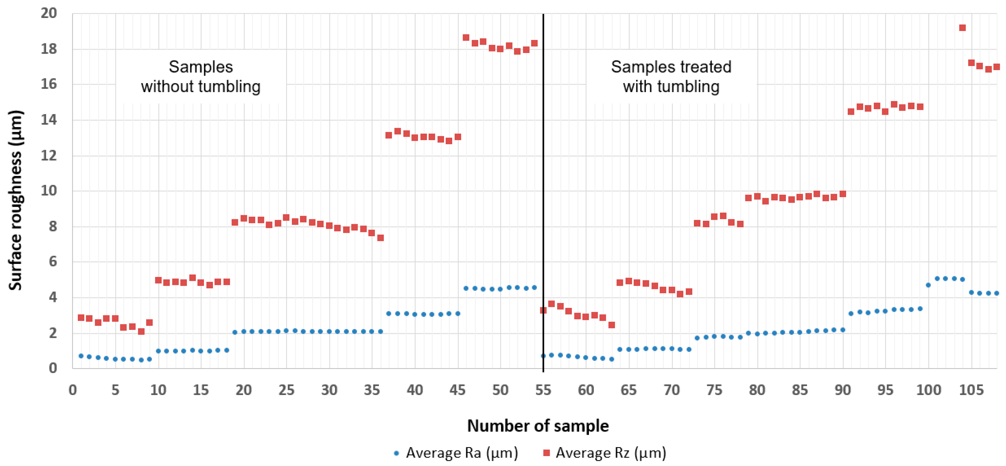
In the beginning, on a selected set of samples, the surface roughness was measured by means of both Mahr MarSurf M300 (MAHR GmbH, Göttingen, Germany) and 3D scanning ALICONA measuring devices (Alicona Imaging GmbH, Graz, Austria). After comparison of all parameters recorded by both measuring devices, no significant differences between measures were found. So, due to a large number of samples and since the measuring by means of ALICONA was significantly longer, authors decided to use 2D analysis and measure surface on 3 spots and calculate an average value of every parameter. The representative parameters Ra (µm) (arithmetical average deviation from a mean line) and Rz (µm) (ten-point height of irregularities) have been chosen for presentation in the paper because they clearly express the behaviour of surface roughness achieved after machining with different cutting feeds. The results have been plotted by means of the graph shown in Figure 8. The parameters Rk, Rpk, Rvk, A1, A2, Mr1 and Mr2 were used for the Abbott curves construction (see Section 5.1.2, Figure 20).
From the graph bellow, it is evident that it managed to produce the cylinders, which surface roughness differed in a jumping way and which unambiguously corresponded to the used feed rate during machining as follows:
f1 = 0.08 mm ≥ ~Ra 0.6
f2 = 0.12 mm ≥ ~Ra 1
f3 = 0.16 mm ≥ ~Ra 2
f4 = 0.2 mm ≥ ~Ra 3
f5 = 0.24 mm ≥ ~Ra 4.5.
At the same time, it can be stated from the measurement results that the surface roughness of the cylinders decreased after tumbling. For the samples with a roughness that was initially low, this drop was not as striking as for cylinders that had initially greater roughness.
4.2. Microhardness and Metallographic Analysis
Although the selected steel EN/DIN 34CrNiMo6 is not considered to be nitriding, it is often nitrided in practice. The samples treated after machining and also samples with a hardened surface by nitriding and electroless nickel plating were analysed through the micro-hardness test HV 0.05 (or HV 0.025) to determine to which the depth could be expected a higher material resistance.
Within the preliminary tests, a microstructure of the tested samples was also evaluated. The samples were cut longitudinally and crosswise—perpendicular to the intended direction of damage by means of a metallographic saw. They were also embedded in the preparation mass, metallographically ground and polished. Metallographic sections were subsequently etched using Nital 3% and then documented using the metallographic microscope MULTICHECK PC 500 (AVYAC MACHINES SAS, Veauche, France). The evaluation only several types of samples with different surface treatment is presented in the article. Their microstructures are shown in Figure 9, Figure 10, Figure 11 and Figure 12 and they are described below.
The microstructure of a sample without surface treatment, machined with the feed per revolution f1 = 0.08 mm is presented in Figure 9. The sample was treated by refinement without next surface hardening. According to Figure 9, the structure of the outer surface is the same as in the core of the material.
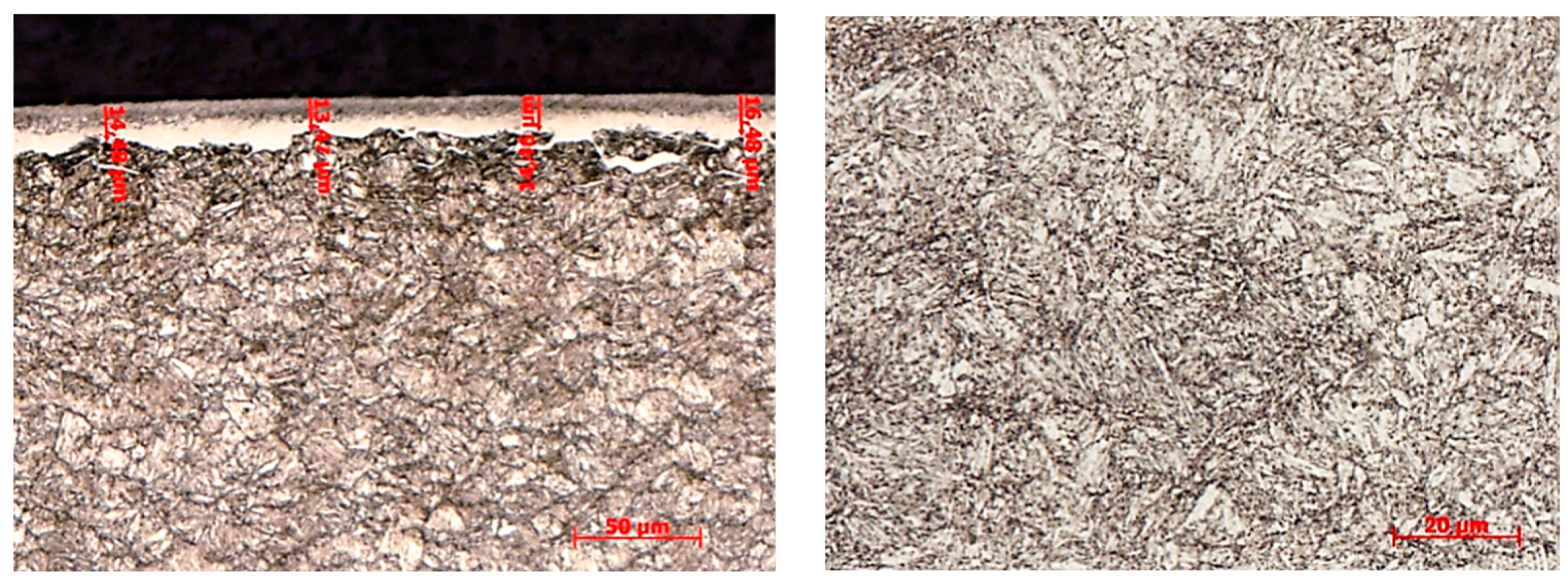
Nitriding sample, machined with the feed per revolution f1 = 0.08 mm is presented in Figure 10. The sample exhibited a white layer thickness of about 15–20 µm, which was compact and didn’t show an inconsistency. The average microhardness of the sample in the core was HV 0.05 = 395.
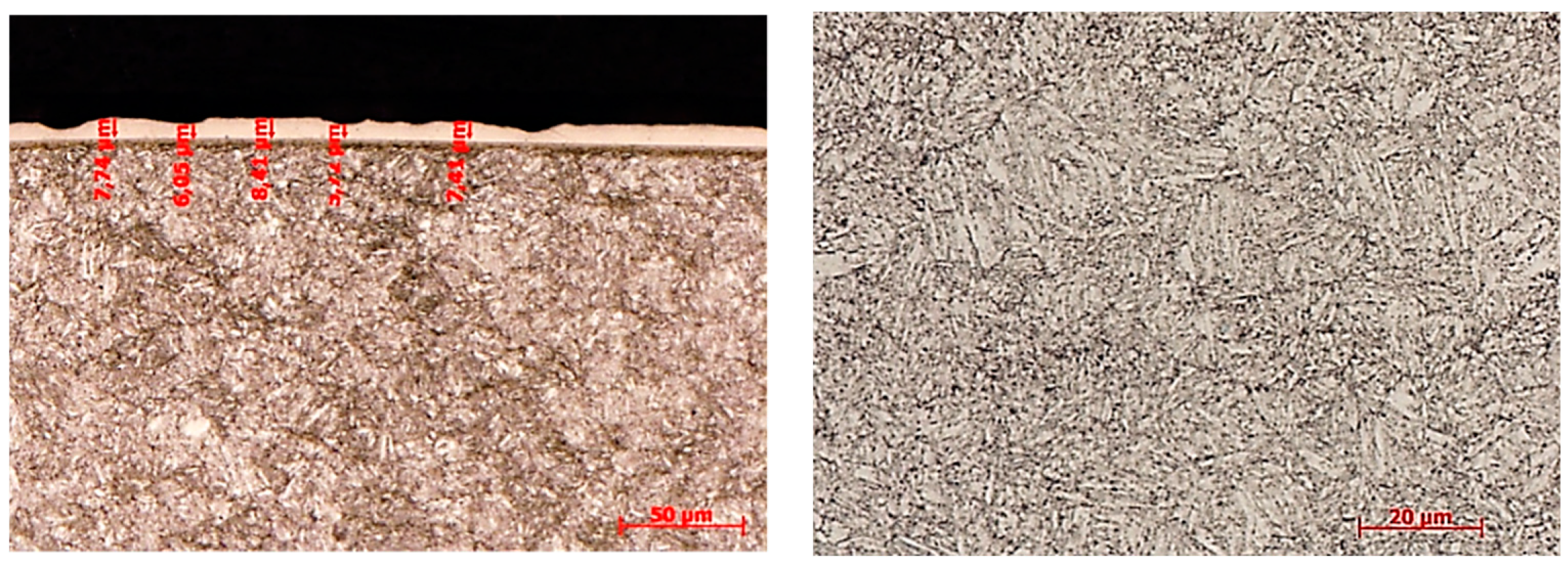
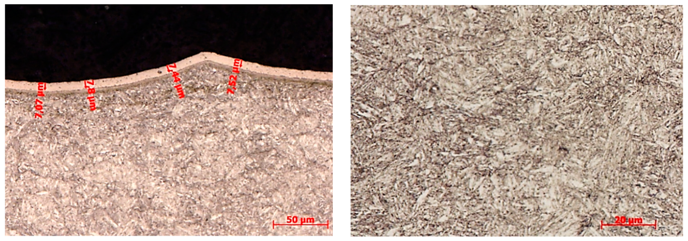
The microstructures of the samples hardened by electroless nickel plating machined with the feed per revolution f1 = 0.08 mm (the surface roughness ~Ra 0.6 µm) is presented in Figure 11 and with the feed per revolution f5 = 0.24 mm (the surface roughness ~Ra 4.5 µm) is presented in Figure 12.
Cylinders hardened by electroless nickel plating have the same layer thickness of approximately 7–8 µm. The layer follows the relief of the surface, it is consistent and without any visible defects. The base material corresponds to the hardness values required in the material tables, but the surface micro-hardness values were lower than expected. The measured microhardness (HV 0.025) of both fine and roughly turned samples with Ni coating deposition is presented in Table 3.
It is clear from Table 3 that the surfaces of cylinders machined with the feed per revolution f1 = 0.08 mm are harder compared to the samples machined with f5 = 0.24 mm. The hardness of the roughly turned surface (and especially of the crosswise cut) is lower. However, this can be influenced by the fact that at a higher roughness at the measured point, the layer is not compact, but there is a “softer” base underneath.
5. Tribological Behaviour of 34CrNiMo6 Steel
5.1. Pin-on-Disk Test
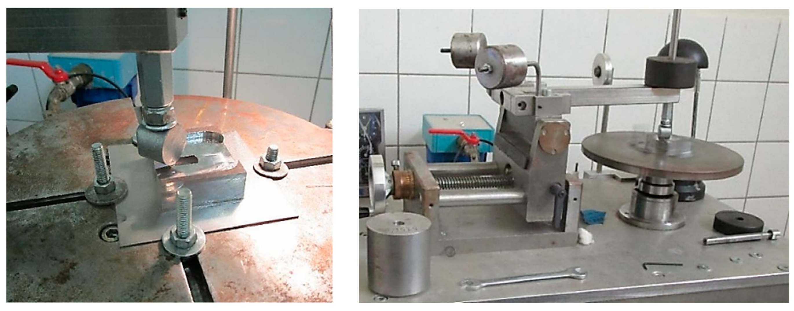
At the first stage of tribological properties of 34CrNiMo6 steel investigation, a testing device—tribometer “PIN-ON-DISC” was designed and manufactured at the WBU in Pilsen. The principle of testing was as follows. Two cylinders were placed in the machine. One specimen was fixed firmly to the tribometer arm holder and the second to the movable holder. The operational load was carried out using weights (utilization of gravitational force). By a movement of the samples relative to each other, a contact load was simulated. After reaching the prescribed number of cycles of contact, the test was discontinued and both samples were turned to be tested in another contact area or to be the samples exchanged. The samples clamping in a holder and the complex view on tribometer used at the testing process are shown in Figure 13.
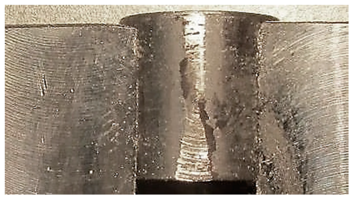
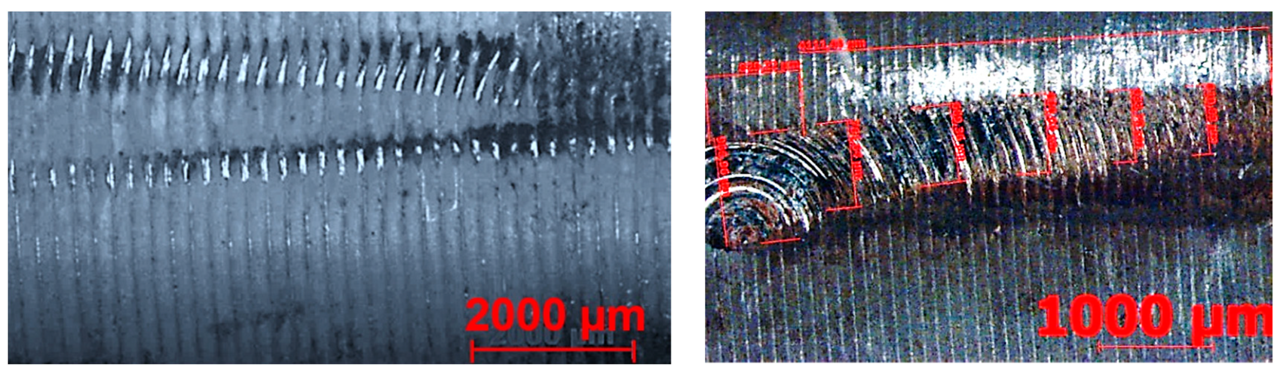
In order to follow the development of the damage, a gradual increase of cycles in the series was chosen: 1.8 × 10³; 5 × 10³; 10 × 103 and 20 × 103 cycles. The sample movement speed was 3 rpm, and the load was selected at 5 N or 10 N. At the end of the test, the generated tribological traces were examined by the stereo magnifying glass. To compare a degree of the wear of all samples, the wear area was selected as a measured parameter. The area better interprets the relative wear than e.g., the track width. The example of wear is presented in Figure 14.
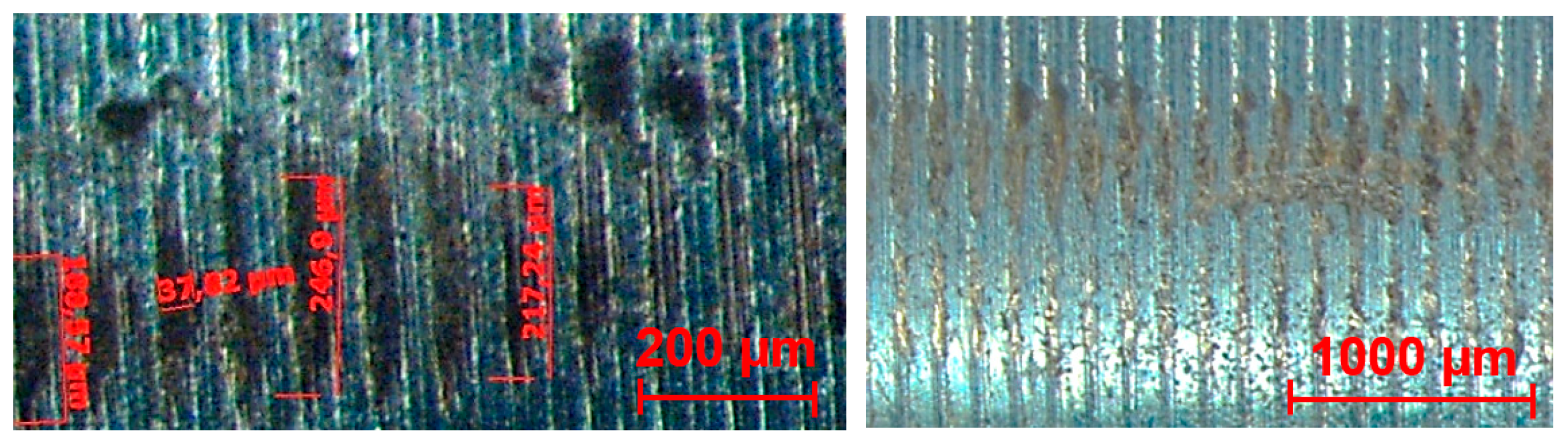
5.1.1. Wear Measuring and Observation
Measured were always the samples that were fixed to the bottom bracket because these samples showed a more measurable and more regular trace of wear. The measurements were done by making photographs where the length and width of the track were measured. If the track tapered, the track was divided into multiple rectangles, and their area was then added together. It was necessary to use 2–3 images per one track evaluation, depending on the created length. In the case of nickel-plated specimens, there was generally no continuous measurable trace. Mostly, only the peaks were worn out after machining. In this case, the tracks had to be measured, averaged and then summed.
Since there is a possibility that the oil layers between the levers may break due to very high Hertzian pressure and there may be limit lubrication between the contact surfaces [42] (see Figure 15), authors decided not to use the oil lubricant. The second reason for not using oil or other lubricant was to accelerate the wear process during the test. It can also be said at this point that the finally produced levers were tested under real conditions (i.e., with lubricant) and the measured wear after long-term tests were very low (or none), so the levers comply with the standard requirements for their safety and reliable operation.
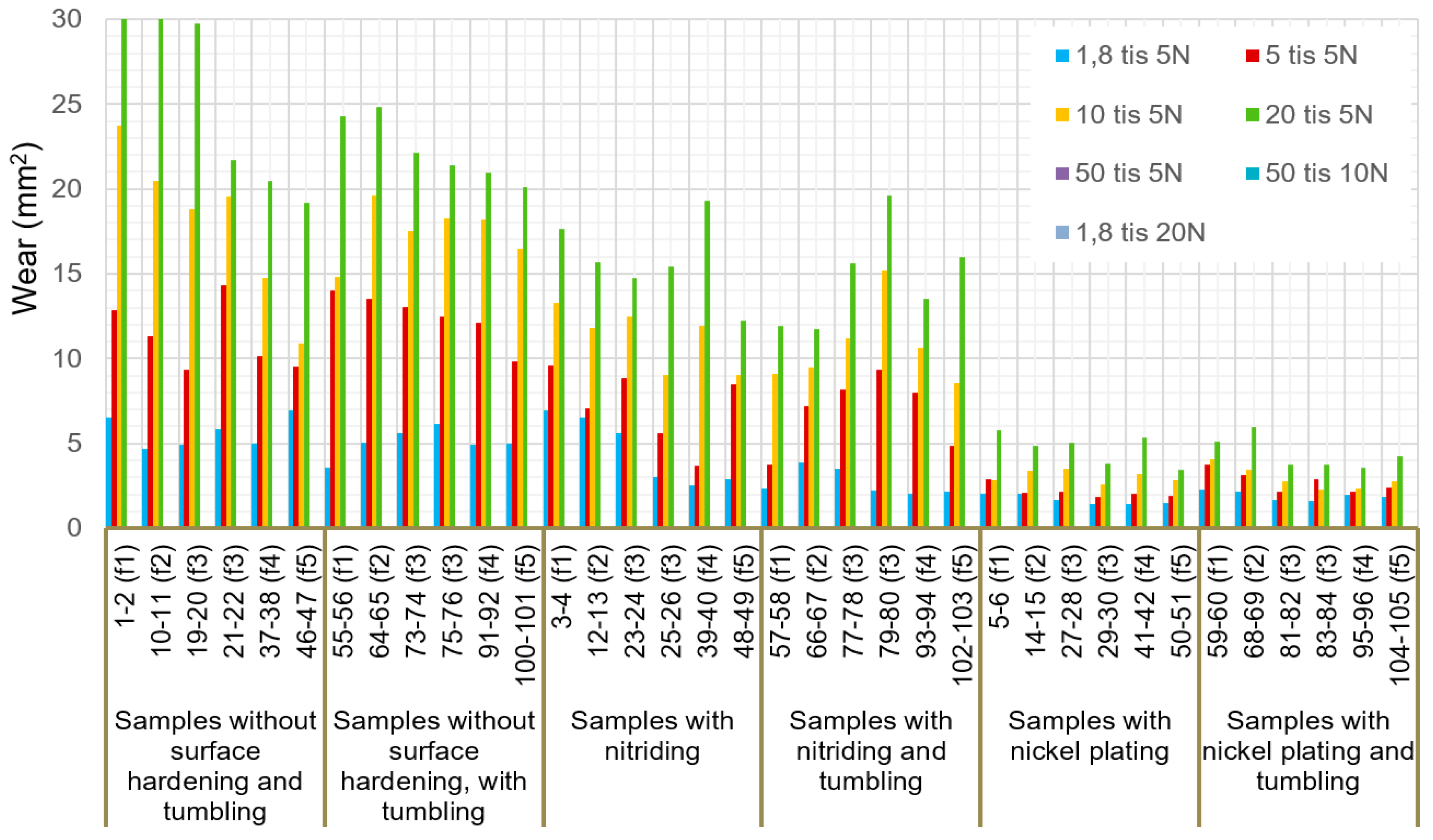
The wear results of all samples are shown in Figure 16 and examples of cylinders’ wear for individual types of surface hardening are shown in Figure 17, Figure 18 and Figure 19.
The samples without surface treatment showed relatively similar abrasion resistance, despite differences in surface roughness. The following pictures in Figure 17 show the damage development of samples No. 11 and 55, which were evaluated as the worst in the tribological test.
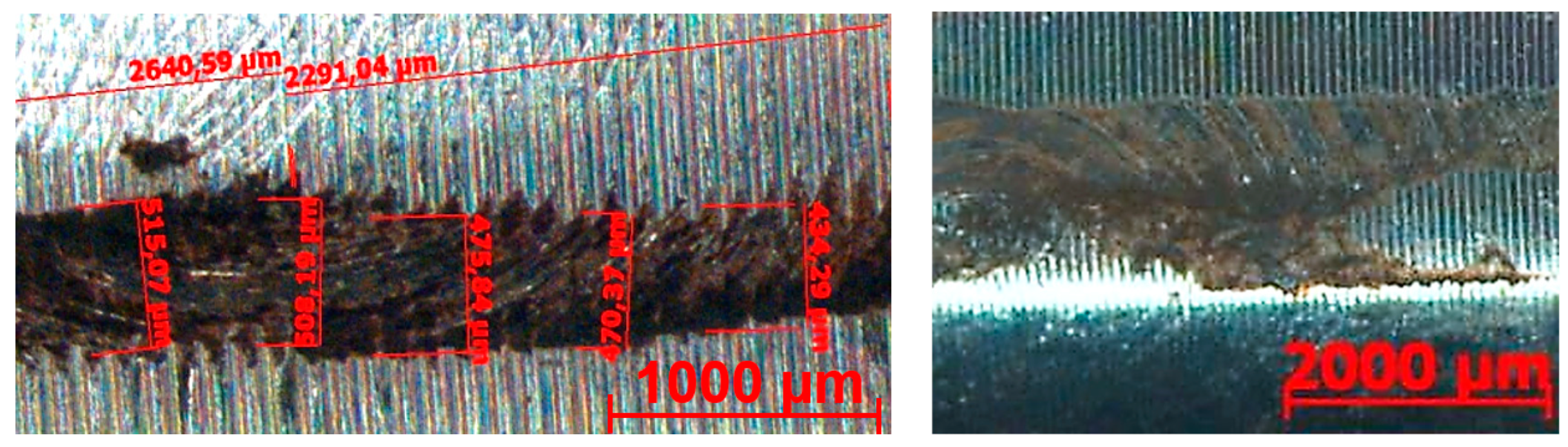
For presentation in the article, the sample No. 49 was selected as a representative of nitriding samples. In Figure 18, the picture on the left side shows the beginning of the damage and on the right, there is a significant breakage (the layer has ceased to function). The effect of surface roughness was manifested only in the samples with higher roughness values.
The smallest wear was measured at the samples, which were hardened by electroless nickel plating. In Figure 19 is presented wear of the sample No. 5 reached after 1.8 × 10³ cycles at a force of 5 N load. As another example can be selected sample num. 27, which didn’t show any wear even after 50 × 103 cycles at 5 N load, because only a discontinuous trace was created that was difficult to measure. Therefore, the sample was loaded again at 100 × 103 cycles by a force of 10 N load. On this sample, in the most stressed area, it was already possible to find a continuous measurable trace with measured surface damage of approximately 920 µm. However, even in this case, it cannot be said that this sample would behave as worn out.
The measured values were statistically processed by ANOVA analysis, which shows the best results for surface and wears analysis. This statistical method consists of evaluating the relationships between the variance of the selected sets. The essence of the method is to perform the so-called decomposition of the total variance into two sub-variations, namely the variation caused by the influence of individual factors and on a part called “noise”, which can be assumed to occur accidentally. The statistical significance of the ratio between these components is then tested in this method. Generally, this method makes it possible to verify whether the monitored factors have a statistically significant effect on the monitored quantities [43].
The monitored factors included: displacement, surface condition (surface hardening) and the number of cycles. In this analysis, some pairs of factors, at which were supposed they could be statistically significant were also studied. When evaluating all these parameters, it was found that the factors Feed, Surface Condition, Number of Cycles, and the factor pairs “Feed-Surface Condition” and “Surface Condition-Number of Cycles” have been statistically significant.
5.1.2. Discussions
Summary from the used surface treatments point of view
It is clear from the table and graphs above that the best wear performance was achieved on samples treated with electroless nickel plating. These coatings, whose hardness is not significantly higher than that of the other types of coatings tested, exhibit excellent tribological properties due to very good lubricating properties. However, due to the relatively thin deposited layers, it is to be assumed that in the event of the layer destruction, the next damage will be rapidly increasing.
The hardness of the nitrided layer was recorded in relatively small depths. However, samples with the nitrided surfaces showed higher wear resistance compared to samples without surface treatment. Due to the small thickness of the hard layer, rapid delamination and spreading of damage occurred. In the early stages of the test, nitrided specimens seemed to have an effect of surface roughness, where a concentration of damage has occurred primarily on the profile peaks that prevented a relatively long time of spreading of the next degree of layer degradation.
Samples only heat-treated showed no difference in a surface quality in dependence on tumbling. Already in the early stages of loading, a worn area was formed on the surface, which rapidly increased.
Summary from the surface roughness point of view
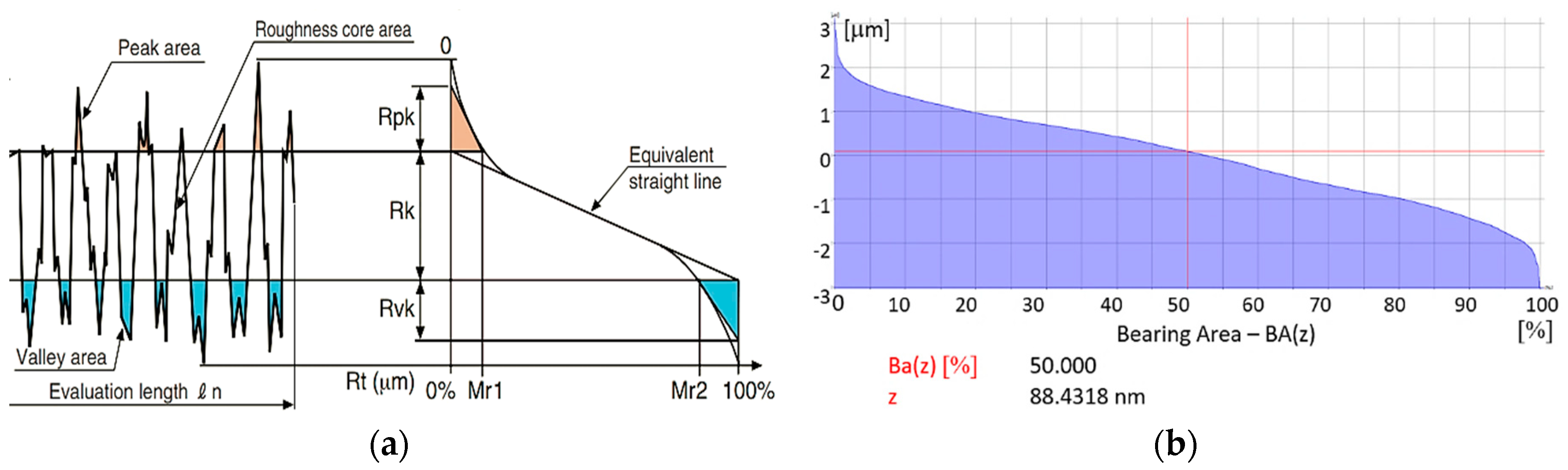
It is also evident from the above graphs that the samples machined with higher feeds per revolution (f3–f5) came out best from the surface roughness point of view. Subsequent surface tumbling had little or no effect on wear. Within the experimental study, the Abbott-Firestone’s curves (AFC) were used for surface roughness evaluation. These curves graphically describe the distribution of material within the profile height and they can be also used for assessing the functional properties of surfaces and their possible exploitation. The principle of AFC construction (according to the standard ISO13565-2:1996) is in Figure 20a, while an example of an AF curve obtained by means of the software belonging to the Mahr MarSurf M300 device (MAHR GmbH, Göttingen, Germany) for sample number 55 is in Figure 20b.
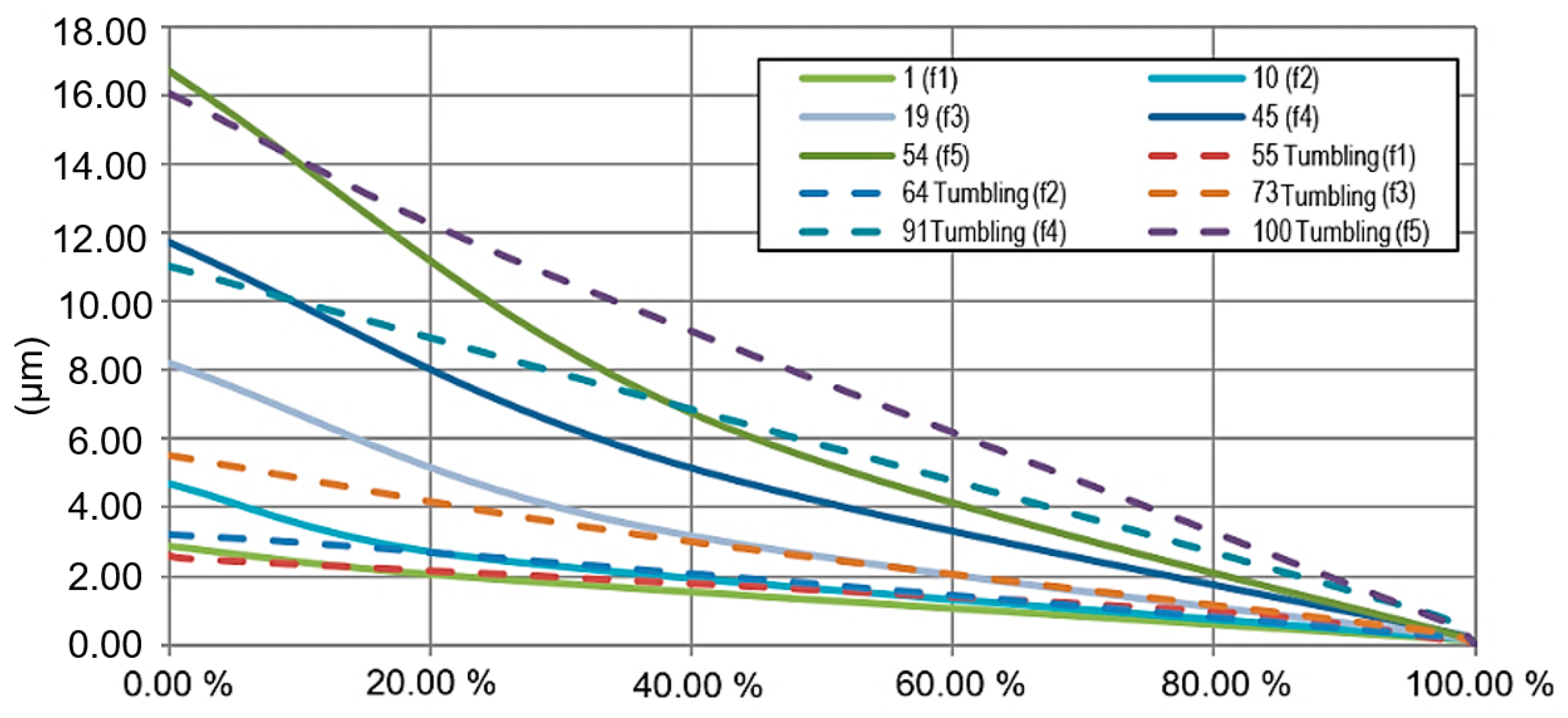
Problem of Mahr MarSurf M300 (MAHR GmbH, Göttingen, Germany) or Alicona (Alicona Imaging GmbH, Graz, Austria) software for data processing is that it can generate only one particular Abbott-Firestone’s curve, and so it is impossible to compare different AF curves in the same ratio. So, the measured values Rk, Rpk, Rvk, A1, A2, Mr1 and Mr2 were used for the bearing area curves construction using MS Excel software (version 1911, Microsoft corporation Inc., Redmond, WA, USA) application. They were plotted based on the principle presented in Figure 20a, what provided a possibility to compare them in one chart and easy to evaluate. The bearing area curves of selected cylinders are presented in Figure 21.
Looking at the bearing area curves in Figure 21, it can be seen how at feeds f4 and f5 the curves are steep. The peaks at the feed f5 reach 16–17 µm. During the initial run-in, the “peaks” usually reduced to about 0.07 µm. Since the levers are in contact with each other, this value needs to be doubled. Such a value (~0.015 µm) is already critical, as the production of the levers should be within an absolute accuracy of about 0.03 mm. The bearing at worse accuracy can no longer absorb deflections higher than 0.1°. If almost 50% of the manufacturing tolerance is “decreased” only due to surface roughness, it unnecessarily increases the cost and complicates production, as more levers would have to be thrown out due to inaccurate.
Another important aspect is that when using higher feeds (and hence higher roughness values), a higher coefficient of friction between the levers results. Given that the levers are flooded with oil, it is not exactly possible to specify how much the roughness of the functional surfaces affects the mutual rolling movement of the levers.
5.2. Frequency Tribological Test
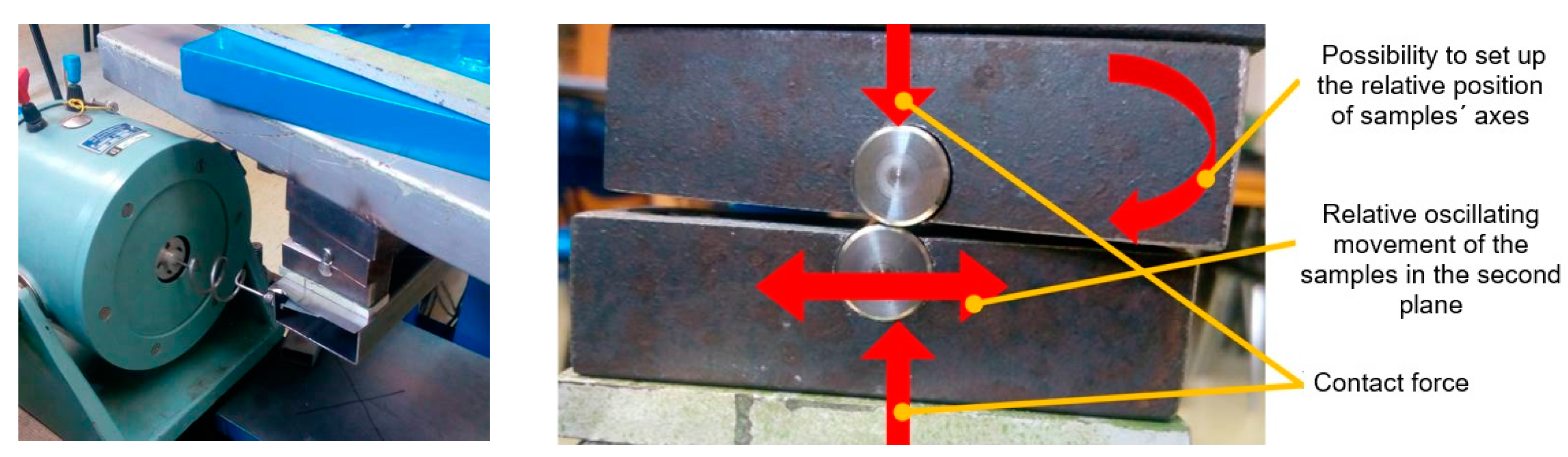
Considering the need to specify the real tribological properties of the levers, a special test facility (Figure 22) was built at WBU in Pilsen, technical prerequisites of which are close to the real conditions of bearing operation.
The oscillating motion was selected on the principle of a frequency exciter with a frequency generator that can work in a fluent frequency change from 0 Hz to 10 MHz. Scanning of vibration intensity was continuously performed using an accelerometer set with a possibility to display measured results at an oscilloscope and to record measured data on PC.
The aim of the proposed frequency load experiments was to compare the behaviour of selected surface treatments and to monitor their response to the frequency load. The frequency test was performed for both the Cylinder/Cylinder assembly and the Cylinder/Plate assembly without lubrication and with the following loading conditions:
| contact force: | 15 N; |
| feed: | ±0.2 mm; |
| oscillation speed: | 50 Hz; |
| a number of oscillations: | 1 × 10⁶. |
Two samples were relatively positioned to each other. The upper sample was firmly clamped in a horizontal bracket and the lower sample was mounted on a movable arm where an operating load was applied through the lever. The core of the electromagnetic coil was resiliently attached to the arm, causing the respective oscillations. Their frequencies were set at 50 Hz, which are the closest to the expected operating frequency of future machine parts.
Within the frequency tribological tests, the samples made from 34CrNiMo6 steel were used, which were either only heat-treated, either nitrided or nickel-plated. Wear documentation was made using a stereo magnifying glass. Due to the fact that very different roughness of samples was in the experiment, using the volume of wear for the evaluation would be burdened with a high error. Since all samples had the same diameter, the wear area and width seemed to be sufficient value for compare. The measurement was carried out by dividing the track according to pictures and then the obtained areas were summed up. The wear width was averaged based on the figures.
It can be stated that all deviations were less than 10%. A minimum of three repetitions of measurements was performed on each sample and if there were any doubts (e.g., the deviation was in the range of 8 to 10%), the samples were tested five times.
5.2.1. Configuration “Cylinder/Cylinder”
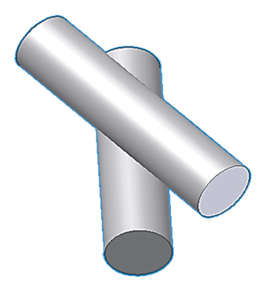
The purpose of this test was to achieve a point contact between the samples and thereby achieve a simulated probable load during the operation of the levers in the turbine when contacting the Cylinder/Cylinder types of surfaces.
The configuration of tested samples was as it is shown in Figure 23 below. Two 12 mm diameter cylinders with the same roughness, provided with the same surface treatment, were offset at 15° to each other and loaded against each other by the weights.
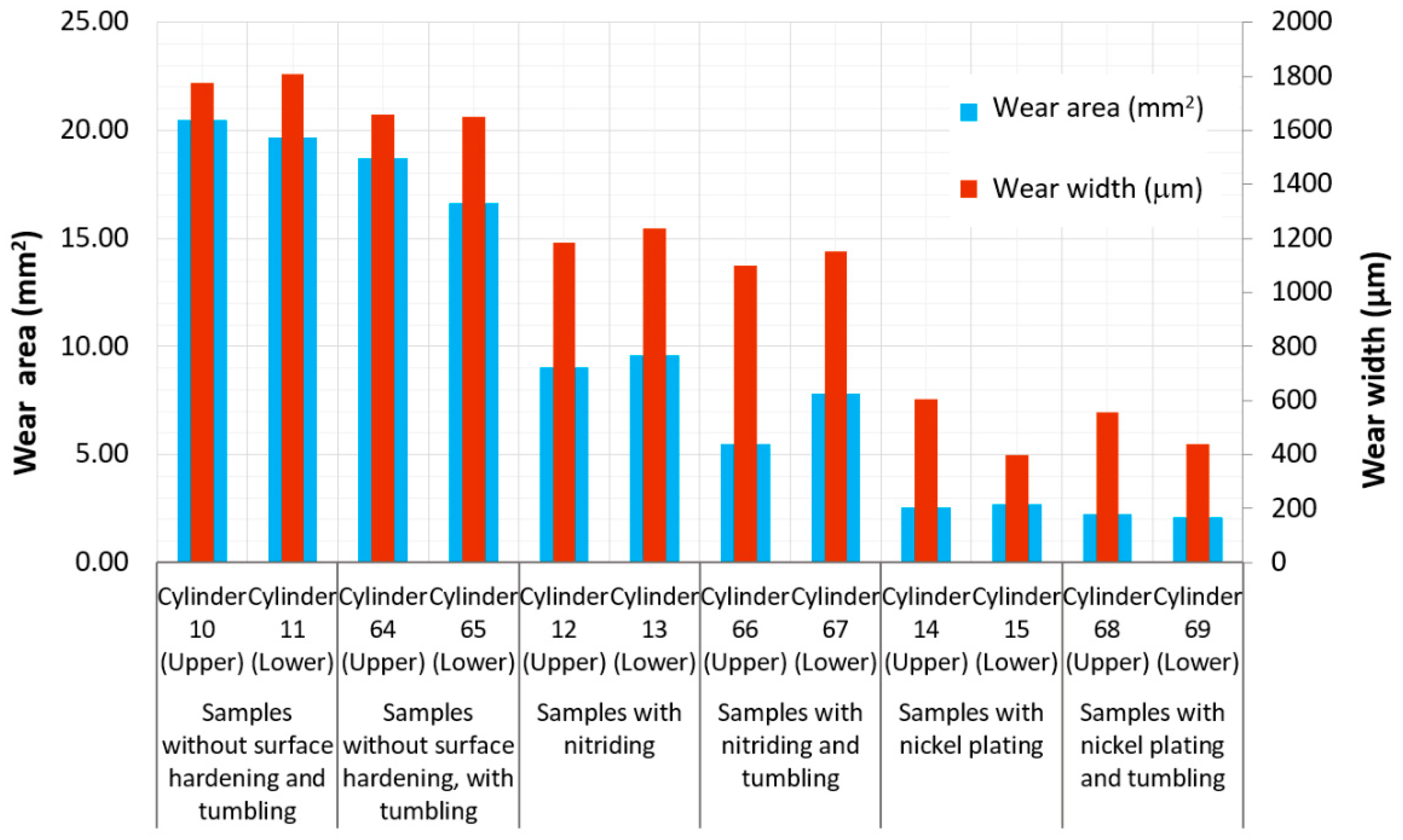
The graph in Figure 24 provides a wear comparison between individual samples. The best results achieved the samples treaded by electroless nickel plating. Their worn area was about half in comparison to nitrided samples and a quarter in comparison with samples, which surface was not treated. However, it cannot be unequivocally said that these surfaces will exhibit four times the resistance to untreated real parts, which will, in addition, be intensively lubricated.
Moreover, some samples showed some fragmentation of the nickel-plated coating at the edge of the trace. The size of these fragments was in the range of units up to tens of micrometre. Due to the oil film thickness of the bearing, which is in the range of 25–40 µm, this value is already critical.
The nitrided specimens showed about a half less wear than the untreated specimens, so the nitride layer partially retained its properties despite the revelation of the base material.
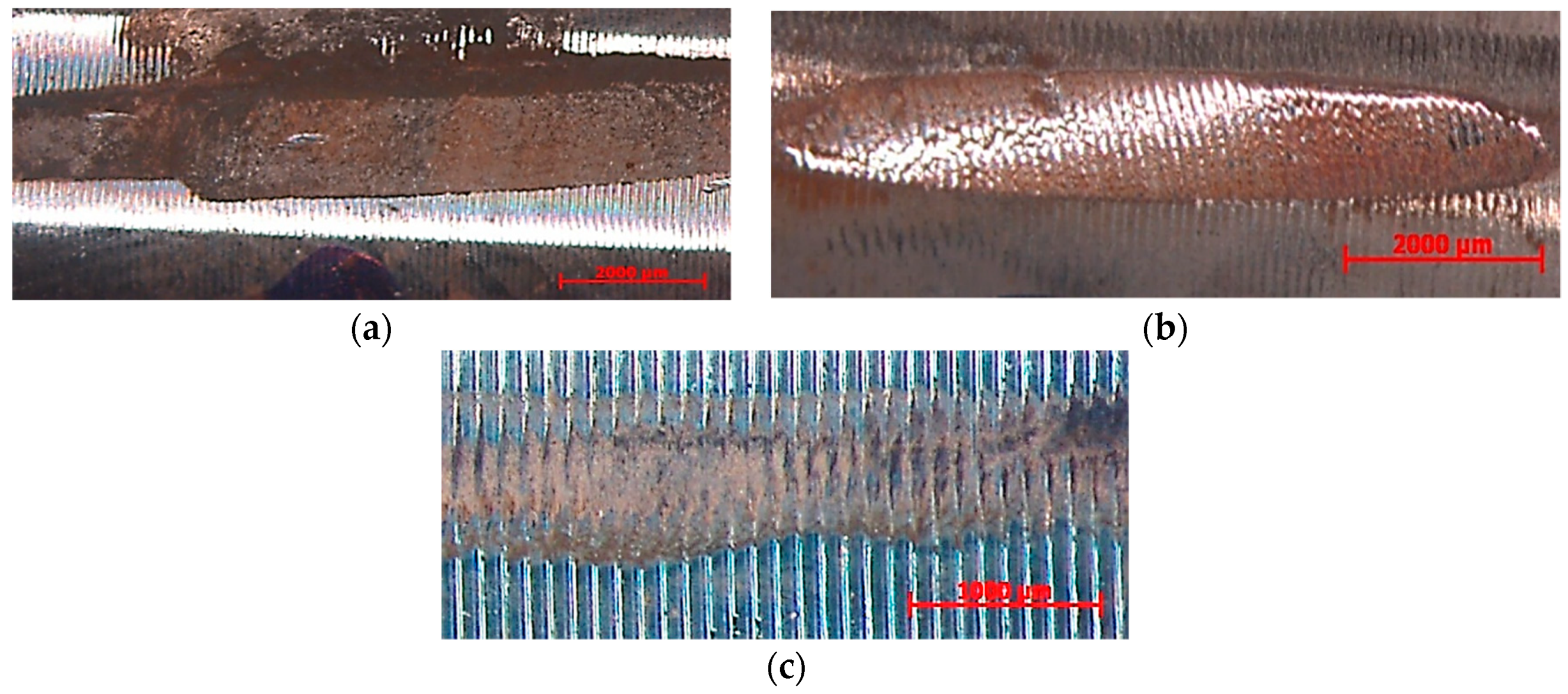
Significant amounts of oxides formed in the process of rubbing the samples against each other appeared on the untreated and nitrided samples. For nickel-plated samples, this amount was smaller. This can be attributed to the very good natural lubricating properties of the nickel surface. Documented wears on selected samples are shown in Figure 25.
5.2.2. Configuration “Cylinder/Plate”
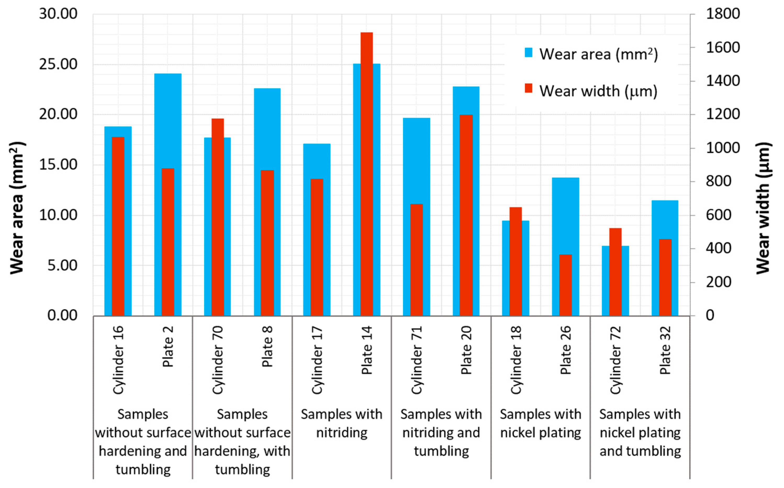
The configuration of tested samples for testing the Cylinder/Plate combination of surfaces is shown in Figure 26. A 12 mm diameter cylinder, provided with the same finish as the plate, was loaded against the plate with weights. Comparison of wear between individual samples is evaluated by means of the graph presented in Figure 27.
From the point of view of worn-out surfaces, the nickel-plated samples were again the best. The wear area of these samples was about half, compared to uncoated and nitrided samples. In this configuration (i.e., Cylinder/Plate), the nickel-plated surface did not prove to be easily susceptible to delamination and dividing in larger portions and thus to the risk of an accident related to oil lubrication. The wear area of the nitrided and uncoated samples was not very different. Here, it depends probably on the thickness of the layer [44].
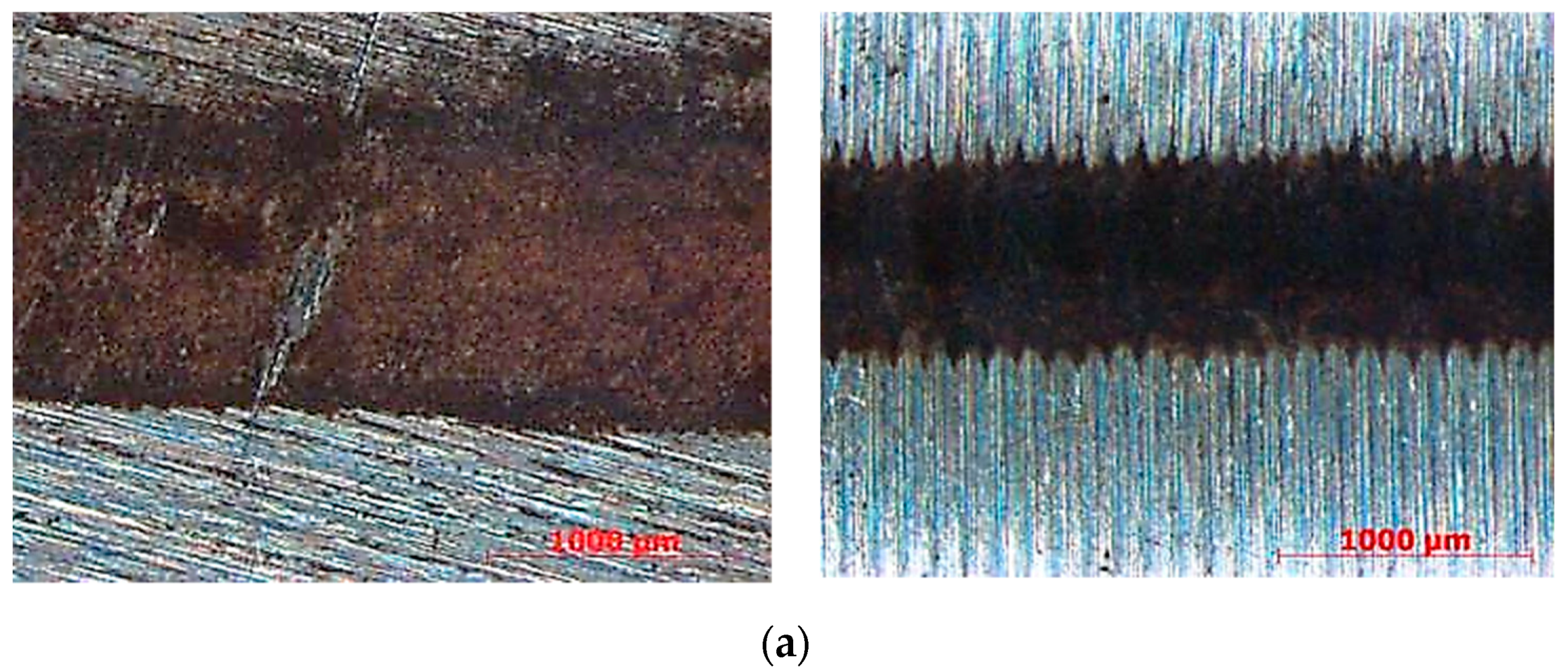
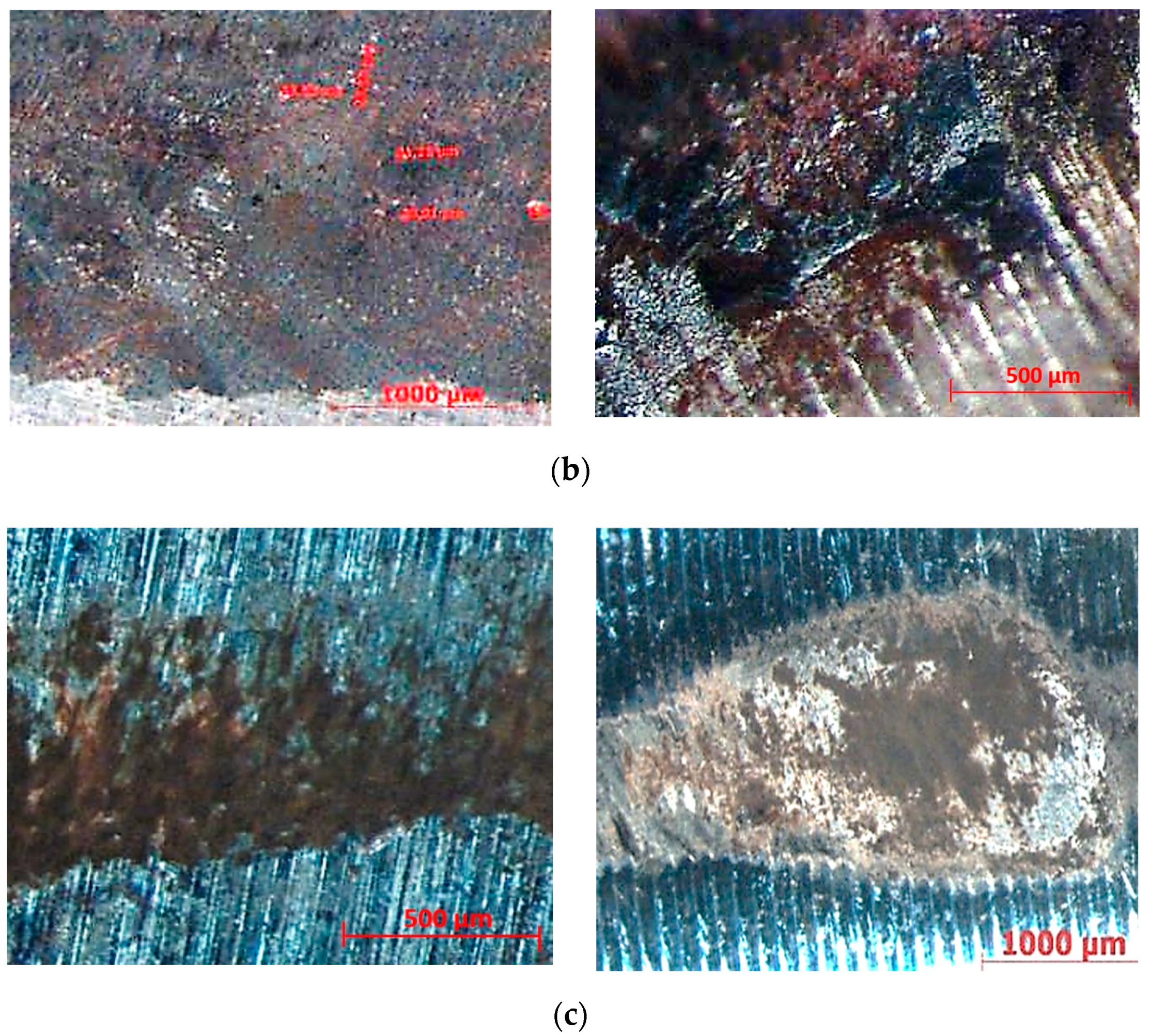
The worn area of the plate was in all cases about 20% larger than that of the cylinders. Documented wears on selected samples are shown in Figure 28a–c.
6. Conclusions
Two types of contact surfaces (Cylinder/Cylinder and Cylinder/Plate) were selected for investigation tribological properties of 34CrNiMo6 steel in the production of a newly designed self-equalizing thrust bearing. Except that all samples were heat-treated, and some of the samples were treated with tumbling, next two types of surface treatment were selected for the surface quality of bearing levers improvement, i.e., nitriding and electroless nickel plating.
Within preliminary tests, the surface roughness, microhardness HV and microstructure of the samples were analysed. The tests confirmed the high influence of the feed on surface roughness. At the same time, it could be stated from the measurement results that the surface roughness of the cylinders decreased after tumbling.
When studied the microhardness (HV 0.025) of fine and roughly turned samples with Ni coating deposition, the results show that surfaces of cylinders machined with the feed per revolution f1 = 0.08 mm are harder compared to the samples machined with f5 = 0.24 mm. The hardness of the roughly turned surface (and especially of the crosswise cut) is lower. However, this can be influenced by the fact that at a higher roughness at the measured point, the layer is not compact, but there is a “softer” base underneath.
Tribological properties of samples were investigated experimentally within Pin-on-Disc and Frequency tests focusing on the wear and surface roughness evaluation. It was observed that the most likely mechanism of wear was abrasive and partially adhesive. It can be also stated based on the results that in all cases the best tribological properties have achieved samples treated by electroless nickel plating compared with the nitrided or only heat-treated samples. The effect of tumbling was not significant.
Within the frequency test of contact surfaces pair Cylinder/Cylinder, the best results achieved the samples treaded by electroless nickel plating. Their worn area was about half in comparison to nitrided samples and a quarter in comparison with samples, which surface was not treated. However, the problem needs to be looked at comprehensively—whether in terms of the kinematics of the mechanism it seems to be the most suitable variant of the Cylinder/Cylinder assembly, and in wear tests, this assembly already showed defects in layer delamination—which is undesirable. This claim was confirmed in subsequent static tests that are not part of this article. Therefore, it was decided to use levers with kinematic Cylinder/Plate pairs when testing prototype self-aligning bearings.
Author Contributions
Conceptualization, M.U. and K.M.; methodology, K.M. and M.U.; validation, K.M.; investigation, M.U. and K.M.; resources, K.M. and M.U.; data curation, M.U.; writing—original draft preparation, K.M.; writing—review and editing, M.U.; supervision, K.M. All authors have read and agreed to the published version of the manuscript.
Funding
This article was funded by the Ministry of Education of the Slovak Republic by grants APVV-19-0550 and KEGA 007TUKE-4/2018.
Acknowledgments
The article was prepared thanks to the Project TE02000232 “Special rotary machine engineering center” with the financial support of TA CZ and thanks to supporting by the Ministry of Education of the Slovak Republic by grants APVV-19-0550 and KEGA 007TUKE-4/2018.
Conflicts of Interest
The authors declare no conflict of interest.
Nomenclature
| ap | depth of cut (mm) |
| vc | cutting speed (mmin−1) |
| f | feed per revolution (mm) |
| rpm | revolution per minute (min−1) |
| Ra | arithmetical average deviation from a mean line (μm) |
| Rz | ten-point height of irregularities (μm) |
| C/C | Cylinder/Cylinder contact surfaces |
| C/P | Cylinder/Plate contact surfaces |
| R | refinement |
| N | nitriding |
| ENP | Electroless Nickel Plating |
| Rk | core roughness depth: Depth of the roughness core profile |
| Rpk | reduced peak height Average height of protruding peaks above the roughness core profile |
| Rvk | reduced valley depths: Average depth of valleys projecting through roughness core profile |
| Mr1 | material portion 1: Level in (%): determined for the intersection line which separates the protruding peaks from the roughness core profile |
| Mr2 | material portion 2: Level in (%), determined for the intersection line which separates the deep valleys from the roughness core profile. |
| A1 | Peak area |
| A2 | Valley area |
References
- DeCamillo, S. Current issues regarding unusual conditions in high-Speed turbomachinery. In 5th EDF/LMS Poitiers Workshop Proceedings; Université de Poitiers: Paris, France, 2006; pp. A1–A10. [Google Scholar]
- Kumar, D.A.; Manisha, D.; Shailendra, J. Study of shaft voltage & bearing currents in electrical machines. In Proceedings of the IEEE Students’ Conference on Electrical, Electronics and Computer Science (SCEECS), Bhopal, India, 1–2 March 2012; pp. 1–4. [Google Scholar]
- Tanaka, T. Approaches to the safer operation of thrust and journal bearings used in turbomachinery. In 10th EDF/Pprime Poitiers Workshop; Université de Poitiers: Paris, France, 2011; pp. A1–A22. [Google Scholar]
- Wodtke, M.; Schubert, A.; Fillon, M.; Wasilczuk, M.; Pajączkowski, P. Large hydrodynamic thrust bearing—Comparison of the theoretical prediction and measurements. In 9th EDF/LMS Poitiers Workshop Proceedings; Université de Poitiers: Paris, France, 2010; pp. M1–M8. [Google Scholar]
- Gregory, R.S. Factors Influencing Power Loss of Tilting-Pad Thrust Bearings. J. Lubr. Technol. 1979, 101, 154–160. [Google Scholar] [CrossRef] [Green Version]
- Zhu, S.; Huang, P. Influence mechanism of morphological parameters on tribological behaviors based on bearing ratio curve. Tribol. Int. 2017, 10, 10–18. [Google Scholar] [CrossRef]
- Malotová, Š.; Čep, R.; Kratochvíl, J.; Šajgalík, M.; Czán, A. Dependence of the Resistance of the Integrated Layers on the Wear of Ceramic Cutting Tool. Manuf. Technol. 2018, 18, 444–448. [Google Scholar] [CrossRef]
- Ettles, C.M.; Knox, R.T.; Ferguson, J.H.; Horner, D. Test Results for PTFE-Faced Thrust Pads, With Direct Comparison Against Babbitt-Faced Pads and Correlation with Analysis. J. Tribol. 2003, 125, 814–823. [Google Scholar] [CrossRef]
- Martsinkovsky, V.; Yurko, V.; Tarelnik, V.; Filonenko, Y. Designing Thrust Sliding Bearings of High Bearing Capacity. Procedia Eng. 2012, 39, 148–156. [Google Scholar] [CrossRef] [Green Version]
- Mikula, A.M. The Leading-Edge-Groove Tilting-Pad Thrust Bearing: Recent Developments. J. Tribol. 1985, 107, 423–428. [Google Scholar] [CrossRef]
- Rohatgi, P.K.; Tabandeh-Khorshid, M.; Omrani, E.; Lovell, M.R.; Menezes, P.L. Tribology for Scientists and Engineers; Springer: New York, NY, USA, 2013; pp. 233–268. [Google Scholar]
- Straka, F. Static Analysis of Self-Equalizing System in Tilting Pad Thrust Bearing; Pilsen Doosan Skoda Power: Pilsen, Czech Republic, 2013. [Google Scholar]
- Pitel, J.; Matiskova, D.; Marasova, D. A new approach to evaluation of the material cutting using the artificial neural networks. TEM J. 2019, 8, 325–332. [Google Scholar]
- Branagan, L.A. Survey of Damage Investigation of Babbitted Industrial Bearings. Lubricants 2015, 3, 91–112. [Google Scholar] [CrossRef]
- Ferroudji, F. Static Strength Analysis of a Full-scale 850 kW wind Turbine Steel Tower. Int. J. Eng. Adv. Technol. 2019, 8, 403–406. [Google Scholar]
- Pantazopoulos, G.; Toulfatzis, A.; Vazdirvanidis, A.; Rikos, A. Analysis of the Degradation Process of Structural Steel Component Subjected to Prolonged Thermal Exposure. Met. Microstruct. Anal. 2016, 5, 149–156. [Google Scholar] [CrossRef]
- Glavatskih, S.B. Tilting Pad Thrust Bearings. In Tribological Research and Design for Engineering Systems; Elsevier: Amsterdam, The Netherlands, 2003; pp. 379–390. [Google Scholar]
- Noda, S.; Zenitani, S.; Yamada, Y.; Sasaki, T. Improved Technologies of Steam Turbine for Long Term Continuous Operation. Mitsubishi JUKO GIHO 2004, 41, 161–165. [Google Scholar]
- Urban, M.; Skopeček, T.; Dolejš, J. Measurement of axial bearings with self-equalized elements and the fixture design for the measuring their maximal misalignement. Proc. Mech. Eng. Technol. 2015, 1, 263–270. [Google Scholar]
- Pantazopoulos, G.A. A Short Review on Fracture Mechanisms of Mechanical Components Operated under Industrial Process Conditions: Fractographic Analysis and Selected Prevention Strategies. Metals 2019, 9, 148. [Google Scholar] [CrossRef] [Green Version]
- Lehocká, D.; Simkulet, V.; Klich, J.; Štorkan, Z.; Krejčí, L.; Kepič, J.; Birčák, J. Evaluation of possibility of AISI 304 stainless steel mechanical surface treatment with ultrasonically enhanced pulsating water jet. In Lecture Notes in Mechanical Engineering; Springer Nature: Basel, Switzerland, 2019; pp. 163–172. [Google Scholar]
- Battez, A.H.; González, R.; Felgueroso, D.; Fernández, J.; Fernández, M.D.R.; García, M.; Peñuelas, I.; Fernandez, R. Wear prevention behaviour of nanoparticle suspension under extreme pressure conditions. Wear 2007, 263, 1568–1574. [Google Scholar] [CrossRef]
- Popescu, N.; Cojocaru, M.; Mihailov, V. Experimental studies on bulk tempering of 34CrNiMo6 steel. Surf. Eng. Appl. Electrochem. 2012, 48, 28–34. [Google Scholar] [CrossRef]
- Cochet, J.; Thuillier, S.; Loulou, T.; Decultot, N.; Carré, P.; Manach, P.Y. Heat treatment of 34CrNiMo6 steel used for mooringshackles. Int. J. Adv. Manuf. Technol. 2017, 91, 2329–2346. [Google Scholar] [CrossRef]
- Ge, Y.; Wang, K. Effect of tempering temperature on precipitate evolution and mechanical properties of 34CrNiMo6 steel. Mater. Tehnol. 2019, 53, 527–534. [Google Scholar] [CrossRef]
- Branco, R.; Costa, J.; Antunes, F. Low-cycle fatigue behaviour of 34CrNiMo6 high strength steel. Theor. Appl. Fract. Mech. 2012, 58, 28–34. [Google Scholar] [CrossRef]
- Li, Y.; Fang, W.; Lu, C.; Gao, Z.; Ma, X.; Jin, W.; Ye, Y.; Wang, F. Microstructure and Mechanical Properties of 34CrMo4 Steel for Gas Cylinders Formed by Hot Drawing and Flow Forming. Materials 2019, 12, 1351. [Google Scholar] [CrossRef] [Green Version]
- Maniee, A.; Mahboubi, F.; Soleimani, R. The study of tribological and corrosion behaviour of plasma nitrided 34CrNiMo6 steel under hot and cold wall conditions. Mater. Des. 2014, 60, 599–604. [Google Scholar] [CrossRef]
- Huang, C.; Lin, X.; Yang, H.; Liu, F.; Huang, W. Microstructure and Tribological Properties of Laser Forming Repaired 34CrNiMo6 Steel. Materials 2018, 11, 1722. [Google Scholar] [CrossRef] [PubMed] [Green Version]
- Abd El-Azim, M.E.; Ghoneim, M.M.; Nasreldin, A.M.; Soliman, S. Effect of various heat treatments on microstructure and mechanical properties of 34CrNiMo6 steel. Z. Metallkd 1997, 88, 502–507. [Google Scholar]
- Costa, J.; Ferreira, J.; Ramalho, A. Fatigue and fretting fatigue of ion-nitrided 34CrNiMo6 steel. Theor. Appl. Fract. Mech. 2001, 35, 69–79. [Google Scholar] [CrossRef] [Green Version]
- Selmy, A.I.; El-Sonbaty, I.; Shehata, F.; Khashaba, U.A. Some factors affecting the accuracy of turned parts. Sci. Bull. Fac. Eng. 1989, 24, 356–368. [Google Scholar]
- Baron, P.; Dobránsky, J.; Pollák, M.; Kočiško, M.; Cmorej, T. The Parameter Correlation of Acoustic Emission and High-Frequency Vibrations in the Assessment Process of the Operating State of the Technical System. Acta Mech. Autom. 2016, 10, 112–116. [Google Scholar] [CrossRef] [Green Version]
- Xiao, L.; Rosen, B.G.; Amini, N.; Nilsson, P.H. A study on the effect of surface topography on rough friction in roller contact. J. Wear 2003, 254, 1162–1169. [Google Scholar] [CrossRef]
- Borghi, A.; Gualtieri, E.; Marchetto, D.; Moretti, L.; Valeri, S. Tribological effects of surface texturing on nitriding steel for high-performance engine applications. Wear 2008, 265, 1046–1051. [Google Scholar] [CrossRef]
- Liu, D.; Zhang, Q.; Qin, Z.; Luo, Q.; Wu, Z.; Liu, L. Tribological performance of surfaces enhanced by texturing and nitrogen implantation. Appl. Surf. Sci. 2016, 363, 161–167. [Google Scholar] [CrossRef]
- Sedlaček, M.; Podgornik, B.; Vizintin, J. Influence of surface preparation on roughness parameters, friction and wear. Wear 2009, 266, 482–487. [Google Scholar] [CrossRef]
- Polcar, T.; Parreira, N.; Novak, R. Friction and wear behaviour of CrN coating at temperatures up to 500 °C. Surf. Coat. Technol. 2007, 201, 5228–5235. [Google Scholar] [CrossRef]
- Kuduzović, A.; Poletti, M.C.; Sommitsch, C.; Dománková, M.; Mitsche, S.; Kienreich, R. Investigations into the delayed fracture susceptibility of 34CrNiMo6 steel, and the opportunities for its application in ultra-high-strength bolts and fasteners. Mater. Sci. Eng. A 2014, 590, 66–73. [Google Scholar] [CrossRef]
- Bayes, D.M. The Physical Properties of Electroless Nickel Coatings. In Proceedings of the EN 95 Conference, Singapore, 21–23 November 1995. [Google Scholar]
- Kiran, K.; Manohar, B.; Divakar, S. A central composite rotatable design analysis of lipase catalyzed synthesis of lauroyl lactic acid at bench-scale level. Enzym. Microb. Technol. 2001, 29, 122–128. [Google Scholar] [CrossRef]
- Wang, Y.; Wang, Q.J.; Lin, C.; Shi, F. Development of a Set of Stribeck Curves for Conformal Contacts of Rough Surfaces. Tribol. Trans. 2006, 49, 526–535. [Google Scholar] [CrossRef]
- Filippov, A.; Nikonov, A.; Rubtsov, V.; Dmitriev, A.; Tarasov, S. Vibration and acoustic emission monitoring the stability of peakless tool turning: Experiment and modeling. J. Mater. Process. Technol. 2017, 246, 224–234. [Google Scholar] [CrossRef]
- Panda, A.; Dobransky, J.; Jančik, M.; Pandova, I.; Kačalova, M. Advantages and effectiveness of the powder metallurgy in manufacturing technologies. Metalurgija 2018, 57, 353–356. [Google Scholar]
Figure 1.
Axial slide bearing with the self-equalizing segment, (a) real view; (b) illustration of force transfer by means of levers.
Figure 1.
Axial slide bearing with the self-equalizing segment, (a) real view; (b) illustration of force transfer by means of levers.

Figure 2.
Self-equalizing bearing with levers (1—bearing body/housing, 2—thrust pad, 3—self-equalizing element (lever), 4—nozzle, 5—floating pressure element).
Figure 2.
Self-equalizing bearing with levers (1—bearing body/housing, 2—thrust pad, 3—self-equalizing element (lever), 4—nozzle, 5—floating pressure element).

Figure 3.
The principle of the lever tilting, (a) without the shaft deflection (misalignment); (b) at the shaft deflection (misalignment).
Figure 3.
The principle of the lever tilting, (a) without the shaft deflection (misalignment); (b) at the shaft deflection (misalignment).
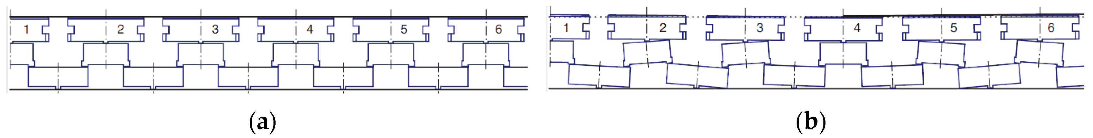
Figure 4.
Comparison of the unworn surface of the lever (left side) with worn (right side highlighted in red).
Figure 4.
Comparison of the unworn surface of the lever (left side) with worn (right side highlighted in red).

Figure 5.
Variants of contact surfaces of lever, (a) Cylinder/Cylinder contacts on both sides of a lever, (b) Cylinder/Cylinder contact on the left side and Cylinder/Plane contact on the right side, (c) Cylinder/Plane contacts on both sides of a lever.
Figure 5.
Variants of contact surfaces of lever, (a) Cylinder/Cylinder contacts on both sides of a lever, (b) Cylinder/Cylinder contact on the left side and Cylinder/Plane contact on the right side, (c) Cylinder/Plane contacts on both sides of a lever.

Figure 6.
A tested cylindrical sample.

Figure 7.
Production of cylinders for experimental testing.

Figure 8.
The surface roughness of tested samples.

Figure 9.
Sample without surface treatment, observation on the edge of the cylinder—magnified 100× (left); detail—magnified 500× (right).
Figure 9.
Sample without surface treatment, observation on the edge of the cylinder—magnified 100× (left); detail—magnified 500× (right).
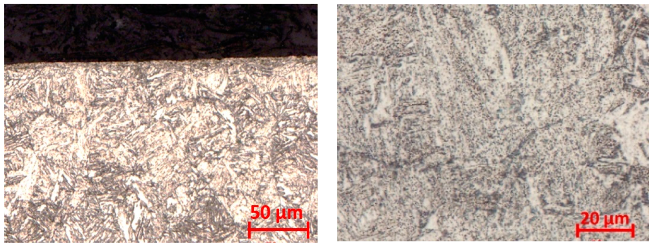
Figure 10.
Nitrided sample—white layer thickness magnified 200× (left); sample centre magnified 500× (right).
Figure 10.
Nitrided sample—white layer thickness magnified 200× (left); sample centre magnified 500× (right).

Figure 11.
Sample electroless nickel-plated, turned with a feed of f1 = 0.08 mm—surface with marked layer thickness—magnified 200× (left); sample center—magnified 500× (right).
Figure 11.
Sample electroless nickel-plated, turned with a feed of f1 = 0.08 mm—surface with marked layer thickness—magnified 200× (left); sample center—magnified 500× (right).

Figure 12.
Sample electroless nickel-plated, turned with a feed of f1 = 0.24 mm—surface with marked layer thickness—magnified 200× (left); sample center—magnified 500× (right).
Figure 12.
Sample electroless nickel-plated, turned with a feed of f1 = 0.24 mm—surface with marked layer thickness—magnified 200× (left); sample center—magnified 500× (right).

Figure 13.
The samples clamping in the holder (left) and the complex view on tribometer (right).

Figure 14.
The example of a wear.

Figure 15.
Lubrication regimes.

Figure 16.
Graphs of all cylinders’ wears—measured on the tribometer.

Figure 17.
Sample No. 11—20× magnification, 1.8 × 10³ cycles of 5 N load (left); Sample No. 55—10× magnification, 5 × 10³ cycles, 5 N load (right).
Figure 17.
Sample No. 11—20× magnification, 1.8 × 10³ cycles of 5 N load (left); Sample No. 55—10× magnification, 5 × 10³ cycles, 5 N load (right).

Figure 18.
Sample No. 49—10× magnification—5 × 10³ cycles, 5 N load (left); Sample No. 13—20× magnification—5 × 10³ cycles 5 N (right).
Figure 18.
Sample No. 49—10× magnification—5 × 10³ cycles, 5 N load (left); Sample No. 13—20× magnification—5 × 10³ cycles 5 N (right).

Figure 19.
Sample No. 5—20× magnification, 1.8 × 10³ cycles of 5 N load (left); Sample No. 27—20× magnification, 20 × 103 cycles, 5 N load (right).
Figure 19.
Sample No. 5—20× magnification, 1.8 × 10³ cycles of 5 N load (left); Sample No. 27—20× magnification, 20 × 103 cycles, 5 N load (right).

Figure 20.
Abbott-Firestone’s curves, (a) construction according to the standard ISO13565-2:1996; (b) AFC obtained by means of software belonging to the Mahr MarSurf M300 device for sample No. 55.
Figure 20.
Abbott-Firestone’s curves, (a) construction according to the standard ISO13565-2:1996; (b) AFC obtained by means of software belonging to the Mahr MarSurf M300 device for sample No. 55.

Figure 21.
The bearing area curves of selected cylindrical samples (No. 1–54 without tumbling and No. 55–108 with tumbling).
Figure 21.
The bearing area curves of selected cylindrical samples (No. 1–54 without tumbling and No. 55–108 with tumbling).

Figure 22.
Frequency tribological testing device: Detail of adjustable holders and vibration exciter; (left), detail of samples positioning with the indication of movement possibilities (right).
Figure 22.
Frequency tribological testing device: Detail of adjustable holders and vibration exciter; (left), detail of samples positioning with the indication of movement possibilities (right).

Figure 23.
Test configuration–position of cylinders with respect to each other.

Figure 24.
Frequency load (all samples of configuration Cylinder/Cylinder together).

Figure 25.
The example of wears of selected samples at tested configuration Cylinder/Cylinder. (a) Sample No. 10 without surface treatment (only heat-treated), 10× magnification; (b) sample No. 66 nitrided, 10× magnification; (c) sample No. 15 treated by electroless nickel plating, 10× magnification.

Figure 26.
Test configuration–position of a cylinder with respect to the plate.
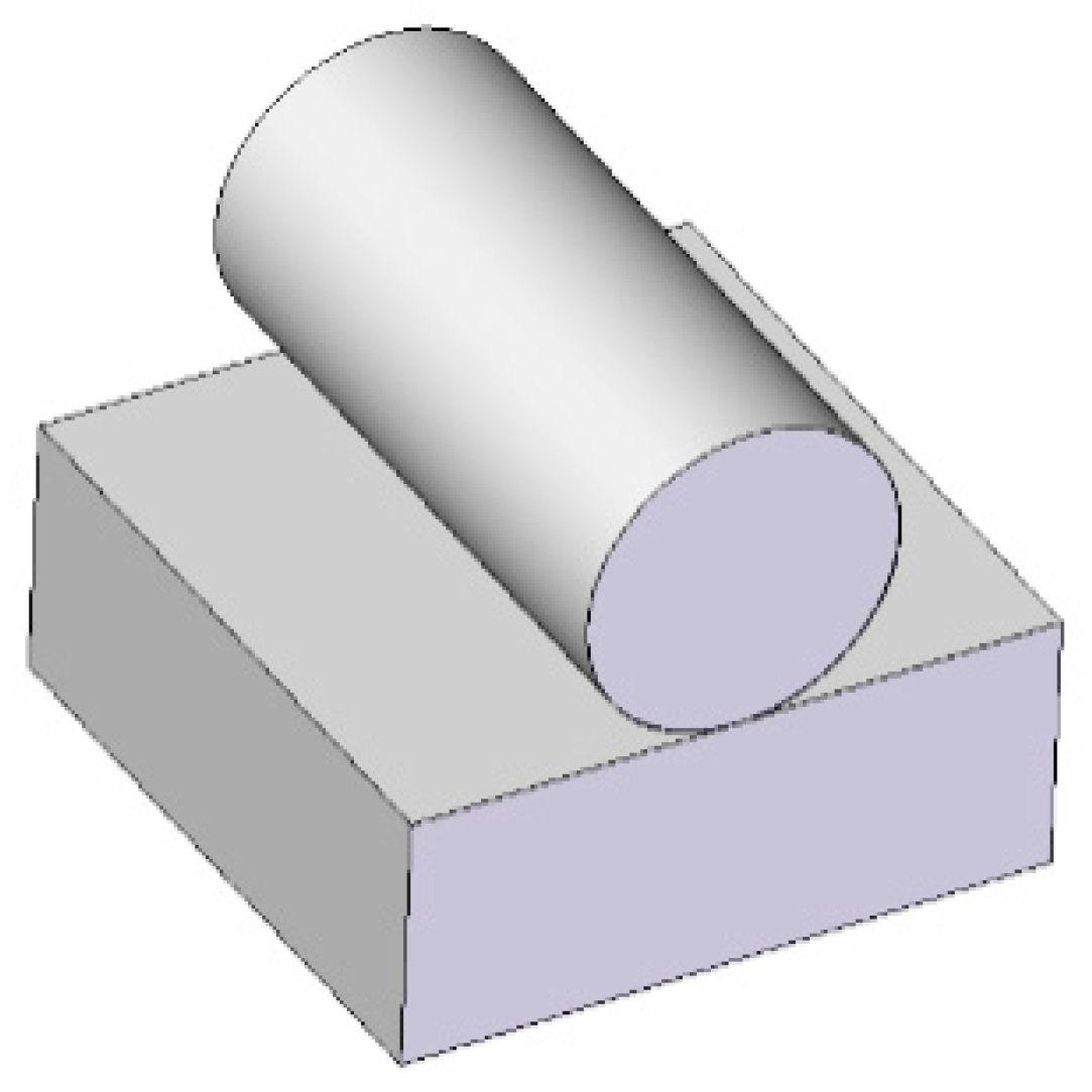
Figure 27.
Frequency load (all samples of configuration Cylinder/Plate together).

Figure 28.
The example of wears of selected samples at tested configuration Cylinder/Plate. (a) Samples without surface treatment (only heat-treated): Plate No. 2—30× magnification (left); Cylinder No. 16, 30× magnification (right). (b) Nitrided samples: Plate No. 14—measurement of layer fragments, 30× magnification (left); Cylinder No. 17—detail of degradation of nitrided layer, 63× magnification (right). (c) Samples treated by electroless nickel plating: Plate No. 32, 40× magnification, (left); Cylinder No. 72, 20× magnification (right).


Table 1.
Chemical composition of the 34CrNiMo6 steel.
| Component | C | Mn | Si | P | S | Cr | Ni | Mo | V | Cu | Al |
|---|---|---|---|---|---|---|---|---|---|---|---|
| (wt.%) | 0.34 | 0.793 | 0.282 | 0.0196 | 0.0052 | 1.72 | 1.55 | 0.221 | 0.0092 | 0.193 | 0.0194 |
Table 2.
Samples with an assigned number and associated characteristics (C/C—Cylinder/Cylinder contact type; C/P—Cylinder/Plane contact type; R—refinement; N—nitriding, ENP—Electroless Nickel Plating).
Table 2.
Samples with an assigned number and associated characteristics (C/C—Cylinder/Cylinder contact type; C/P—Cylinder/Plane contact type; R—refinement; N—nitriding, ENP—Electroless Nickel Plating).
| Without Tumbling | With Tumbling | Feed | Type of Surface | Heat Treatment | Without Tumbling | With Tumbling | Feed | Type of Surface | Heat Treatment | Without Tumbling | With Tumbling | Feed | Type of Surface | Heat Treatment |
|---|---|---|---|---|---|---|---|---|---|---|---|---|---|---|
| Sample (Cylinder) Number | Sample (Cylinder) Number | Sample (Cylinder) Number | ||||||||||||
| 1 | 55 | f1 | C/C | R | 19 | 73 | f3 | C/C | R | 37 | 91 | f4 | C/C | R |
| 2 | 56 | R | 20 | 74 | R | 38 | 92 | R | ||||||
| 3 | 57 | R + N | 21 | 75 | R | 39 | 93 | R + N | ||||||
| 4 | 58 | R + N | 22 | 76 | R | 40 | 94 | R + N | ||||||
| 5 | 59 | R + ENP | 23 | 77 | R + N | 41 | 95 | R + ENP | ||||||
| 6 | 60 | R + ENP | 24 | 78 | R + N | 42 | 96 | R + ENP | ||||||
| 7 | 61 | C/P | R | 25 | 79 | R + N | 43 | 97 | C/P | R | ||||
| 8 | 62 | R + N | 26 | 80 | R + N | 44 | 98 | R + N | ||||||
| 9 | 63 | R + ENP | 27 | 81 | R + ENP | 45 | 99 | R + ENP | ||||||
| 10 | 64 | f2 | C/C | R | 28 | 82 | R + ENP | 46 | 100 | f5 | C/C | R | ||
| 11 | 65 | R | 29 | 83 | R + ENP | 47 | 101 | R | ||||||
| 12 | 66 | R + N | 30 | 84 | R + ENP | 48 | 102 | R + N | ||||||
| 13 | 67 | R + N | 31 | 85 | C/P | R | 49 | 103 | R + N | |||||
| 14 | 68 | R + ENP | 32 | 86 | R | 50 | 104 | R + ENP | ||||||
| 15 | 69 | R + ENP | 33 | 87 | R + N | 51 | 105 | R + ENP | ||||||
| 16 | 70 | C/P | R | 34 | 88 | R + N | 52 | 106 | C/P | R | ||||
| 17 | 71 | R + N | 35 | 89 | R + EN | 53 | 107 | R + N | ||||||
| 18 | 72 | R + ENP | 36 | 90 | R + ENP | 54 | 108 | R + ENP | ||||||
Table 3.
Microhardness (HV 0.025) of fine and roughly turned samples with Ni coating deposition.
| HV 0.025 | f1 = 0.08 mm | f1 = 0.24 mm | ||||||
|---|---|---|---|---|---|---|---|---|
| Cross-Cut | Longitudinal Cut | Cross-Cut | Longitudinal Cut | |||||
| Surface | Core | Surface | Core | Surface | Core | Surface | Core | |
| Average Value | 621 | 392 | 225 | 382 | 451 | 375 | 671 | 386 |
| Deviation | 18 | 19 | 23 | 13 | 108 | 17 | 11 | 26 |
© 2020 by the authors. Licensee MDPI, Basel, Switzerland. This article is an open access article distributed under the terms and conditions of the Creative Commons Attribution (CC BY) license (http://creativecommons.org/licenses/by/4.0/).
Share and Cite
MDPI and ACS Style
Urban, M.; Monkova, K. Research of Tribological Properties of 34CrNiMo6 Steel in the Production of a Newly Designed Self-Equalizing Thrust Bearing. Metals 2020, 10, 84. https://doi.org/10.3390/met10010084
AMA Style
Urban M, Monkova K. Research of Tribological Properties of 34CrNiMo6 Steel in the Production of a Newly Designed Self-Equalizing Thrust Bearing. Metals. 2020; 10(1):84. https://doi.org/10.3390/met10010084
Chicago/Turabian StyleUrban, Marek, and Katarina Monkova. 2020. "Research of Tribological Properties of 34CrNiMo6 Steel in the Production of a Newly Designed Self-Equalizing Thrust Bearing" Metals 10, no. 1: 84. https://doi.org/10.3390/met10010084
Note that from the first issue of 2016, this journal uses article numbers instead of page numbers. See further details here.