Article

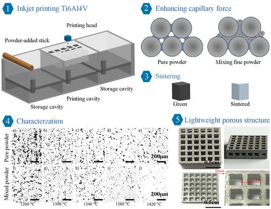
Enhancing the Capillary Force of Binder-Jetting Printing Ti6Al4V and Mechanical Properties under High Temperature Sintering by Mixing Fine Powder

1
Printable Electronics Research Center, Suzhou Institute of Nano-tech and Nano-Bionics, Chinese Academy of Sciences, Suzhou 215123, China
2
School of Mechanical and Ocean Engineering, Jiangsu Ocean University, Lianyungang 222005, China
*
Authors to whom correspondence should be addressed.
Metals 2020, 10(10), 1354; https://doi.org/10.3390/met10101354
Submission received: 7 August 2020 / Revised: 30 September 2020 / Accepted: 5 October 2020 / Published: 10 October 2020
(This article belongs to the Special Issue State-of-Art within 3D Printing and Advanced Machining Processes)

Abstract

:
Binder jet 3D printing (BJ3DP) is an additive manufacturing technology that selectively deposits binder on powder to form a three-dimensional green body followed by sintering process. The low strength of green body and metallurgical issues limit the manufacture of Ti6Al4V parts with high-performance and that are lightweight. In this study, thermal-bubble inkjet technology was used to print Ti6Al4V parts via jetting low-concentration in-situ polymer binders. In addition, a method for mixing fine powder was used to enhance the capillary force of the powder bed and mechanical properties of the parts. The results show that the capillary force was enhanced from 8.35 kPa for pure powder to 16.27 kPa for mixed powder by mixing fine powder. The compression strength of green body was enhanced from 1.5 MPa to 3.21 MPa. After sintering, the sample with mixed powder sintered at 1420 °C for 2 h had achieved a maximum density of 95.2%, microhardness of 316 HV, and yield stress of 589 MPa. The relative density of 95.2% of Ti6Al4V parts fabricated by BJ3DP technology in our study is significantly higher than the value reported in the existing literature. Finally, the porous structure with a size of 550 μm was fabricated. Results presented demonstrate that BJ3DP can produce Ti6Al4V parts with excellent properties.

Graphical Abstract

1. Introduction

Additive manufacturing (AM) is a technology that can be used to manufacture high-accuracy and highly complex structural parts. As one of the AM technologies, binder jet 3D printing (BJ3DP) has attracted a lot of attention due to its advantages, such as a much lower cost and more efficient manufacturing capability. BJ3DP technology takes place at low temperatures by selectively depositing binder materials on powder materials to form a three-dimensional green body. Then, the green body must be post-processed to achieve functional densities by deboning and sintering processes [1,2,3,4,5]. From a metallurgical perspective, BJ3DP is now well established for Ni-based alloys and tool steels [6,7,8]. In terms of high activity Ti alloys, the research is still in the early stages of development. The BJ3DP of Ti alloys has attracted the interest because it can produce geometric shapes that cannot be achieved by traditional powder metallurgy methods, and it is expected to realize the lightweight design of Ti alloys. In addition, the parts of BJ3DP will not produce defects, such as residual stress and cracks caused, compared with selective laser melting.
As a relatively new engineering material, Ti alloys have been widely used in the fields of biomedicine, automotive, and aerospace due to its advantages of high strength to weight ratio, superior corrosion resistance, excellent biocompatibility, and low elastic modulus. Previously, several attempts were made to manufacture Ti alloys with BJ3DP [9,10,11,12]. Barui et al. [13] used Washburn model to quantify the capillary ink infiltration time in a porous powder bed of finite thickness, and successfully manufactured Ti6Al4V parts with strength reliability and cytocompatibility. El-Hajje et al. [14] fabricated Ti alloy parts with fracture strength of 245.7 MPa and density of 3.1 g/cm3 by using BJ3DP technology. Wiria et al. [15] used BJ3DP technology to fabricate a porous Ti implant prototype and obtained components with a compressive strength of 455 MPa. However, the research on the mechanical properties of green body has not been reported in the literature before. In addition, the Ti alloy parts fabricated by the above-mentioned researchers are all used in the biomedical field, and they are not devoted to improving the density and mechanical properties of Ti alloy parts.
The high binding strength can support the removal of high-precision microstructures from the powder bed, thereby realizing the lightweight design of BJ3DP technology in terms of microstructures. Obviously, increasing the binder content can improve the mechanical strength of the green bodies. Nevertheless, too much binder is not preferred because the binder is only the support material that needs to be decomposed by heat during the sintering process. In terms of metallurgy, as per authors’ knowledge, the highest density of Ti alloy parts fabricated with BJ3DP technology is only 84.2% as reported [16]. On the one hand, the slow diffusion of Al and V tend to prohibit densification. On the other hand, the reactivity of Ti easily reacts with C and O decomposed by the polymer to form refractory compounds. The hot isostatic pressing (HIP) sintering can be used to improve density, and another method of adding sintering aids can be performed. However, the HIP method has limited applicability because the green body has complex geometries and internal cavities. In addition, the sintering aids method is also not preferred because it affects the purity of the alloy. Therefore, enhancing the bonding strength between the binder and the powder and increasing the sintered density of the part are particularly important to expand the application fields of BJ3DP titanium alloy parts.
In this study, thermal-bubble inkjet (TIJ) technology was used to eject low concentration and environmentally friendly in-situ polymer binder ink due to its lower cost, higher nozzle density, and higher print speed compared to piezoelectric inkjet (PIJ) [17]. Ti6Al4V, one of the most difficult materials to handle in 3D AM processes, was chosen as the research object of BJ3DP. In addition, a method for mixing fine powder with coarse powder was proposed, which has been used in powder metallurgy processing [18]. Mixing fine powder can not only increase the density of the powder bed and the coordination number of powder particles, but also contribute to the metallurgical densification process. First, the forming principle of BJ3DP by capillary infiltration of binder solution into the powder bed was illustrated. Then, the effect of mixing fine powder on the capillary force of powder bed and properties of green bodies was studied by experiment. After sintering, the properties of BJ3DP-printed parts such as density, shrinkage, microstructure, phase formation, and mechanical properties were characterized in detail. Finally, the microstructures of Ti6Al4V parts were also successfully fabricated. These results might provide new directions to improve properties of BJ3DP-printed Ti6Al4V parts and new applications of BJ3DP, such as the field of micro-aircraft.

2. Materials and Methods

2.1. Materials

A gas atomized spherical Ti6Al4V powder (Beijing AMC Powders Metallurgy Technology Co., Ltd., Beijing, China), with two different types, was used as the powder bed material. One type is pure powder with particle size of 15–53 μm, and the other is mixed powder with particle size of 0–20 μm and 15–53 μm at a weight ratio 1:4. The selection of this ratio increases the density of the powder without affecting the fluidity required by powder spreading in the printing process. The fine powder with particle size of 0–20 μm was not used directly due to its poor fluidity. The particle size distribution of the original powder and the microstructure of the pure powder and mixed powder were characterized as shown in Figure 1. The chemical composition was given in Table 1. Additionally, the water-based binder with ethanol (68 vol%) and polyvinylpyrrolidone (PVP, 7.5 g per 100 mL) was developed by our team. The surface tension and viscosity of binder were measured as 25.8 mN/m and 4.1 mPa.s, respectively.

2.2. 3D Printing Processes

Prismatic specimens of dimensions 10 mm × 10 mm × 10 mm and tensile specimens of dimensions 100 mm × 8 mm × 6 mm were printed using the 3D printer RF 2006T (Nantong RealFast print technology Co., LTD, Nantong, China). The printhead with a nozzle diameter of 40 μm was used (Suzhou RealFast print technology Co., LTD, Suzhou, China). The layer thickness was set to 100 μm, the moving speed of print head was set to 8 mm/s, the drop speed was set to 9 m/s, the moving speed of infrared heating lamp was set to 15 mm/s.
After completing the printing process, the entire powder bed was cured at 180 °C in a vacuum for 2 h so that the green body could be successfully removed from the surrounding loose powder. The green bodies were unbound and sintered in a tube furnace under a vacuum (the vacuum level was ~10–3 bar) with the following heating profile: the green bodies were heated from room temperature to 480 °C with a rate of 5 °C/min, then heated and ramped at 10 °C/min to 1200 °C, and then heated and ramped at 5 °C/min to sintering temperature (1260, 1300, 1340, 1380, 1420, and 1460 °C), then held at the sintering temperature for 2 h, then cooled and ramped at 3 °C/min to 600 °C, and finally cooled down to room temperature naturally.

2.3. Characterization Methods

The microstructure of the pure powder and mixed powder were characterized by a laser particle size analyzer (Mastersize 3000, Malvern, UK). The chemical composition was measured by a spectrometer (ICP-OES, Beijing, China). The densities of the powder bed were measured by volumetric density method with precision balance (0.01 mg resolution). The contact angle was measured by a video optical contact angle measuring instrument (OCA15EC, Dataphysics, Raiffeisenstrabe, Germany). According to Archimedes’ principle, the densities of the sintered samples were measured by an electronic density meter (Fubrs, FK-120X, Xiamen, China). The densities and the pore size of the sintered samples were measured by an optical microscope (Olympus BX53M, Tokyo, Japan). The dimensions of the parts after sintering were measured to calculate the shrinkage with vernier calipers. Microstructure observation and elemental composition analysis of the as-printed and sintered samples were conducted with a scanning electron microscope (SEM; Quanta FEG 250, Hillsboro, OR, USA) equipped with energy dispersive x-ray spectroscopy (EDS; Quanta FEG 250, Hillsboro, OR, USA). The sintered samples were polished and etched using a reagent for metallographic analysis. The phase compositions of the sintered samples were characterized by XRD analysis (D8ADVANCE, Bruker, Karlsruhe, Germany). The Vickers hardness values of the sintered samples were measured by using a Vickers hardness testing machine (HVS-30Z, Shanghai Precision Instrument Co., Ltd., Shanghai, China). The Instron 3366 electronic universal testing machine (Instron Corporation, Norwood, MA, USA) was used to measure the compression (ASTM E9-09) and tensile strength (ASTM E8-04) with ASTM Standards [19,20]. The test speed of the compression strength was set to 0.5 mm/min, and the test speed of the tensile strength was set to 0.1 mm/min.

3. Results and Discussion

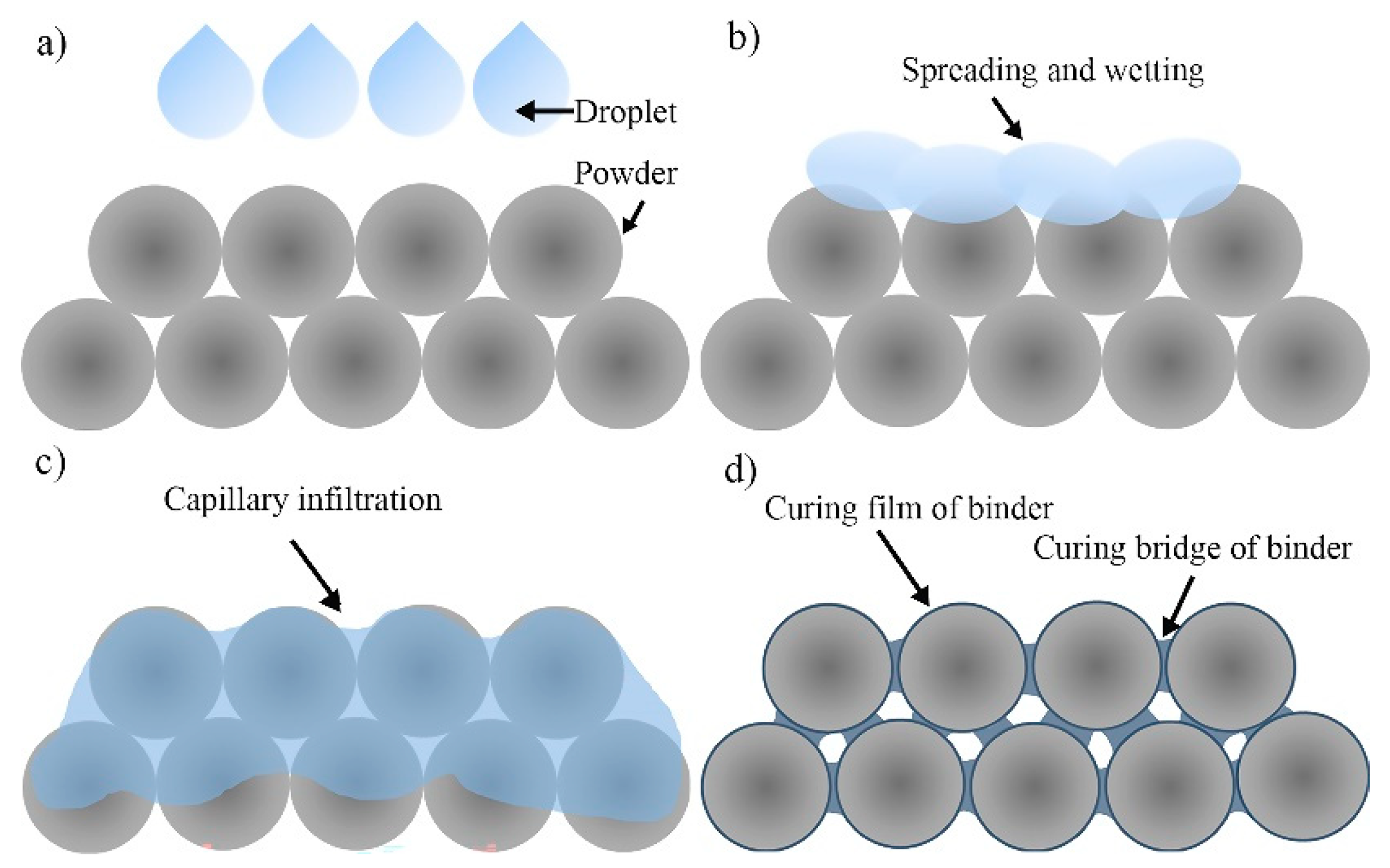
3.1. Principle of Capillary Infiltration of Polymer Binder for BJ3DP

To illustrate the principle of capillary infiltration 3D printing, a proposed model for close-packed arrangement of spherical powder of equal size is shown in Figure 2. Note that, the powder bed can be considered as a capillary tube. In the beginning, the binder droplets are ejected from the nozzle and selectively deposited to the powder bed (Figure 2a). The initial kinetic energy drives the droplet to continue spreading on the powder surface (Figure 2b). Due to the capillary pressure (P) in the porous bed, the binder solution actively infiltrates into the powder by the effect of the capillary force (Figure 2c). Capillary pressure is related to surface tension (γ), effective capillary radius (r), contact angle (θ), density ( ρ 0 ), gravity (g), and vertical capillary height (h), and which satisfies the following equation [21],
P = 2 γ r c o s θ ρ 0 g h
When the powder bed is heated, the water in the solution evaporates, and polymer binder is cross-linked with itself. The self-crosslinking polymer binder forms a cured film on the particle surface. In addition, the self-crosslinking polymer binder acts as the “bridge” between adjacent particles, which contributes to bond the powder particle (Figure 2d). Finally, the green body is fabricated and prepared for sintering.

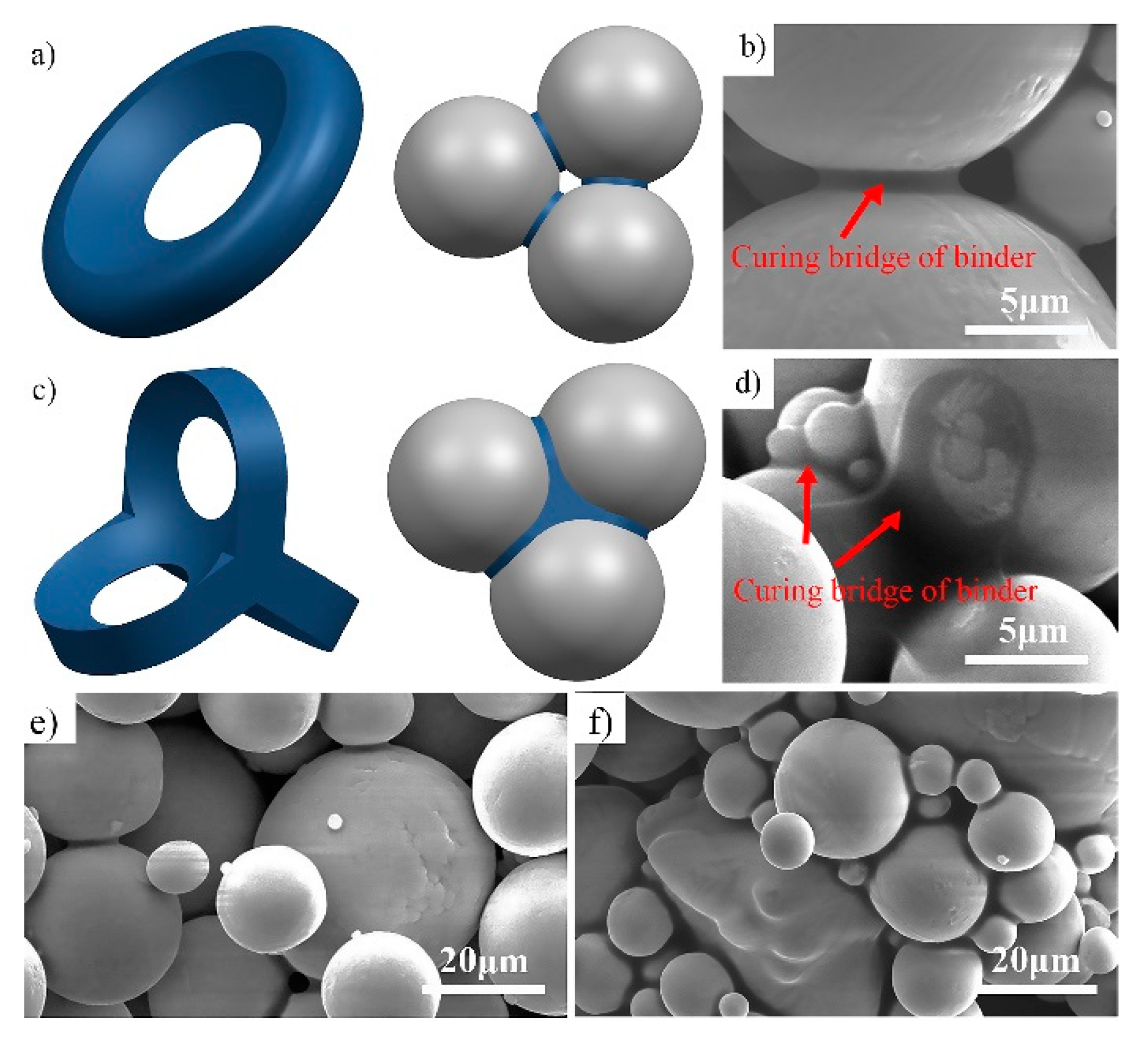
3.1.1. Enhance Capillary Force of BJ3DP by Mixing Fine Powder

In this section, experimental characterization and theoretical calculation are adopted to study the effect of mixing fine powder on the capillary force. On one hand, the density fraction of the powder bed increases by mixing fine powder, which determines the value of the effective capillary radius of the powder bed. The relationship between effective capillary radius ( r ) of the porous bed, porosity ( p ), and particle size (D) was studied by Barui et al., as shown below [13],
r = p 1 p D 3
In the theoretical calculation, the porosity of the porous bed with pure powder and mixed powder was measured at 49% and 45%, respectively. The particle size of D10 of mixed powder as 6.08 μm was considered. As a result, the value of effective capillary radius is estimated to be 1.66 μm. Based on experimental data with the particle size of D10 of pure powder as 23.5 μm, the value of the effective capillary radius of powder bed with pure powder is estimated to 7.53 μm by using the above method.
Furthermore, the wettability of binder ink and powder particles is also affected by the density fraction. The wettability between binder and powder particles of pure powder and mixed powder was measured by contact angle as shown in Figure 3. The results show that the initial contact angle of binder ink on the surface of pure powder and mixed powder are found to be 83° and 87°, respectively. The process of spreading and infiltration are accompanied by a decrease in contact angle. In particular, the spreading and infiltration time of binder ink on the surface of pure powder is only 0.2 s, while that on the surface of mixed powder is 2 s.
In fact, the gravity-assisted pressure is negligible compared to the capillary pressure, so the capillary pressure of Equation (1) can be expressed in terms of the above parameters as [21],
P = 2 γ r c o s θ
Putting the values of surface tension, effective radius, and contact angle in Equation (4), it can be calculated that the capillary pressure of pure powder and mixed powder in the powder bed is 8.35 kPa and 16.27 kPa, respectively. Notably, the capillary pressure of mixed powder is twice that of pure powder. This result indicates that the capillary force is significantly enhanced by mixing fine powder. Such analysis will be further used to explain the compression strength of green bodies in a later subsection.

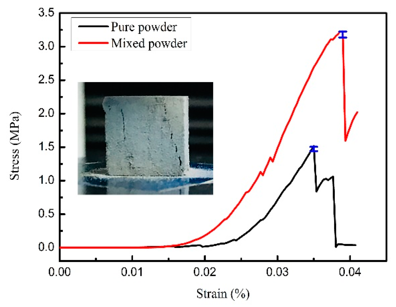
3.1.2. Compression Strength of the Green Body

Figure 4 shows the compression strain-stress curve of green bodies. The results show that the compression strength of samples with pure powder and mixed powder are 1.5 MPa and 3.21 MPa, respectively. In particular, the compression strength of the green bodies mixed with fine powder is twice that of the samples with pure powder.
A reliable model and experiment characterization are used to explain the results, as shown in Figure 5. It is easy to understand that there are two main structural modes of self-crosslinked polymer binder as a bridge between adjacent particles [22], which are also confirmed by SEM of samples (Figure 5a,c). One is a single structure of bridge formed between adjacent particles (Figure 5a,b), the other is a staggered structure of bridge formed by binder between multiple particles (Figure 5c,d). Obviously, the mechanical properties of staggered structure are superior to those of single structure. Figure 5e,f show the microstructure of samples with pure powder and mixed powder. It can be found that a small amount of large pores are distributed in the sample with pure powder. Meanwhile, the pores of samples with mixed powder are filled with a large number of fine particles, which produces a large number of small pores distributed throughout the whole sample. Based on the analysis in the previous section, the mixing of fine powder reduces the effective capillary radius and enhances the capillary force. The binder solution is more likely to accumulate in the narrow space of the neck of adjacent particles and fill the small pores. During the heating process, the self-crosslinking of the polymer binder contributes to form a bridge with a staggered structure, even covering fine particles (Figure 5f). However, almost only single structures of bridge exist, and no bridge with a staggered structure is found in the pure powder sample (Figure 5e). Therefore, mixing fine powder contributes to form more curing bridges with staggered structures and enhances the compressive strength of the green body.

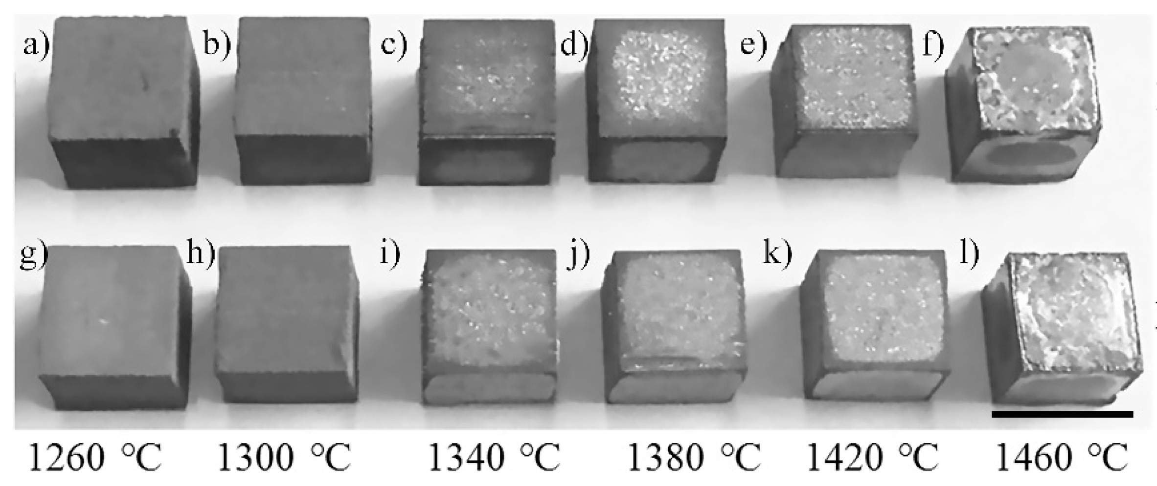
3.2. The Appearance Morphology of the Sintered Samples

Figure 6 shows the appearance morphology of the samples sintered from 1260 °C to 1460 °C. The sintered samples show some shrinkage due to binder removal and the sintering densification. Samples of pure powder and mixed powder show similar appearances at the same temperature. As the sintering temperature increases, the metallic luster on the surface of samples becomes more obvious. Meanwhile, the dark area is observed due to oxidation. When the sintering temperature is 1460 °C, the samples are all warped due to over-sintering.

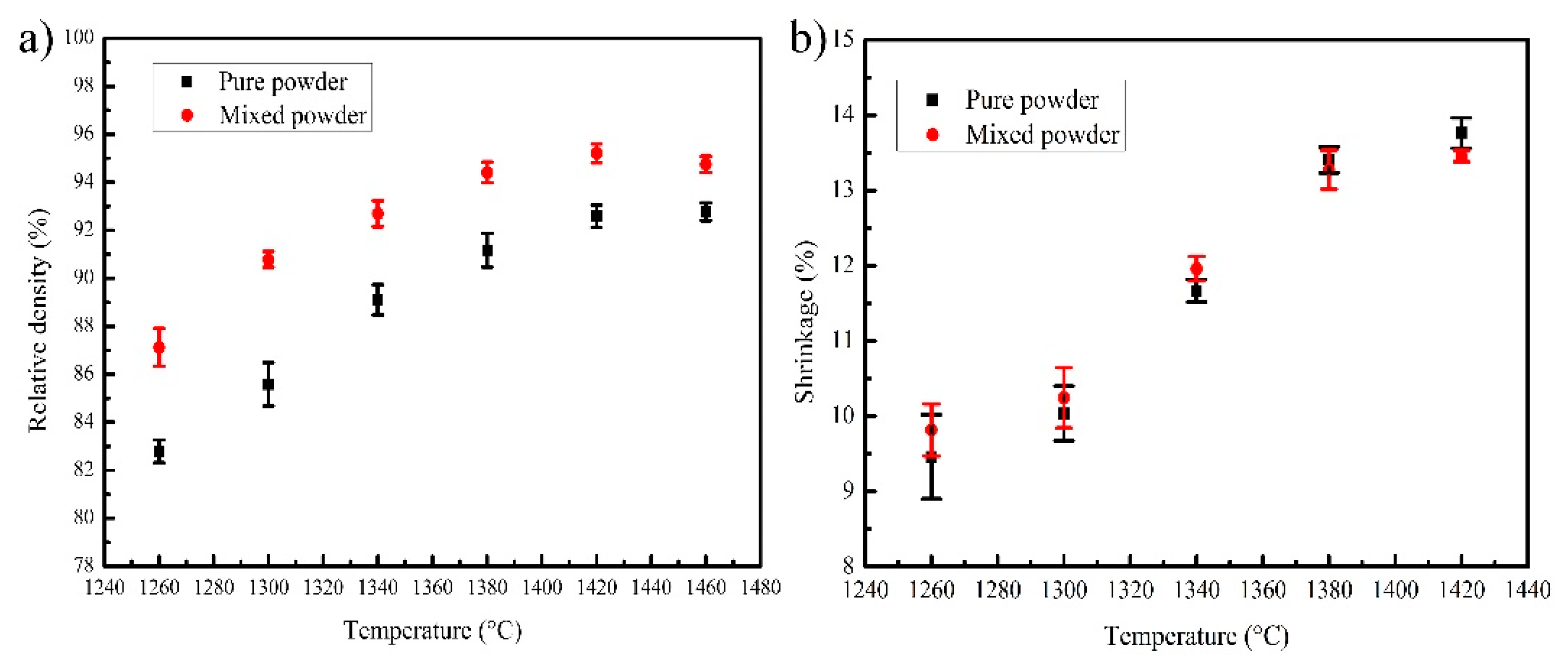
3.3. Relative Density and Shrinkage of the Sintered Samples

Figure 7a shows the relative density of sintered samples that is measured by using Archimedes’ method. As the sintering temperature increases from 1260 to 1420 °C, the relative density of samples sintered with pure powder and mixed powder increases from 82.7% to 92.6% and from 87.1% to 95.2%, respectively. The sample sintered with mixed powder is denser than that sintered with pure powder at the same sintering temperature. When the sintering temperature increases to 1460 °C, the relative density of pure powder samples increase slightly to 92.7%, but the relative density of mixed powder samples decreases to 94.7%. Therefore, when the sintered temperature was 1420 °C, the maximum relative density of 95.2% was achieved for the sintered samples with mixed powder. In the field of Ti6Al4V alloys manufactured by BJ3DP technology, the highest relative density was reported by Stevens et al. [16], who fabricated components with an average relative density of 84.2%. In this study, the relative density of 95.2% is significantly higher than that of previously reported results by BJ3DP technology. In fact, our result is close to the Ti6Al4V alloy samples with a relative density of 96% fabricated by the pressing method reported by Villa et al. [23]. Other studies have reported the use of HIP technology to manufacture completely dense parts [24].
As shown in Figure 7b, the transverse linear shrinkage of sintered samples shows a similar trend to the relative density as the temperature increases. The difference is that the shrinkage of sintered samples with mixed powder is larger than that of pure powder at lower sintering temperatures of 1260–1340 °C, while the opposite situation occurs at higher sintering temperatures of 1380–1420 °C. The maximum shrinkage of samples was measured to be 13.9% for pure powder and 13.4% for mixed powder, respectively.
As shown in Figure 8, the solid volume fraction and maximum pore size are measured by characterizing the cross sections of sintered samples using an optical microscope, and the quantitative results are shown in Table 2. As the sintering temperature increases, the solid volume fraction increases. The large and irregular interconnected pores become small and disconnected spherical pores due to the process of densification (Figure 8), especially for samples sintered with mixed powder (Figure 8f–j). The sintered sample with mixed powder achieves the maximum solid volume fraction of 97.1%, and its maximum pore size decreases to 35.1 μm. Note that there is a slight difference between the density measured by Archimedes and the solid volume fractions measured by the optical image, which is likely due to the small pores that are missed in the optical micrographs.
Unlike compacted PM parts, the densities of green bodies are low during the debonding process due to the thermal decomposition of the binder. In the process of powder metallurgy sintering, the samples gradually shrink and their densities increase as the powder particles melt and fill the pores. As the sintering temperature increases, the powder metallurgy becomes more sufficient, which contributes to further fusing of powder particles. Nevertheless, sintered samples with full density cannot be obtained even if the sintering temperature exceeds the solidus. This is because the C and O elements decomposed by the binder react with highly active Ti to produce refractory TiC and TiO2, which hinders the densification process. On the other hand, the samples mixed with fine powder tend to obtain higher relative density. Fine powder particles produce a high quantity of small pores distributed through the entire part; while coarse powder particles produce a small number of large pores, heterogeneously distributed in the sample. It is easy to understand that small pores are more likely to shrink and dense due to particle melting. Furthermore, the fine powder particles not only provide higher surface energy, but also can increase the powder coordination number due to the filling of larger pores with the fine particles (Figure 5c). According to German research, the function of the coordination number (Nc) and fractional density (f) satisfy the following equation [25]:
N c = 2 + 11 f 2
Obviously, the coordination number is positively correlated with fractional density. The above results can reasonably explain the fact that the sintering density of Ti6Al4V parts can be enhanced by mixing fine powder at constant sintering temperature in this study.

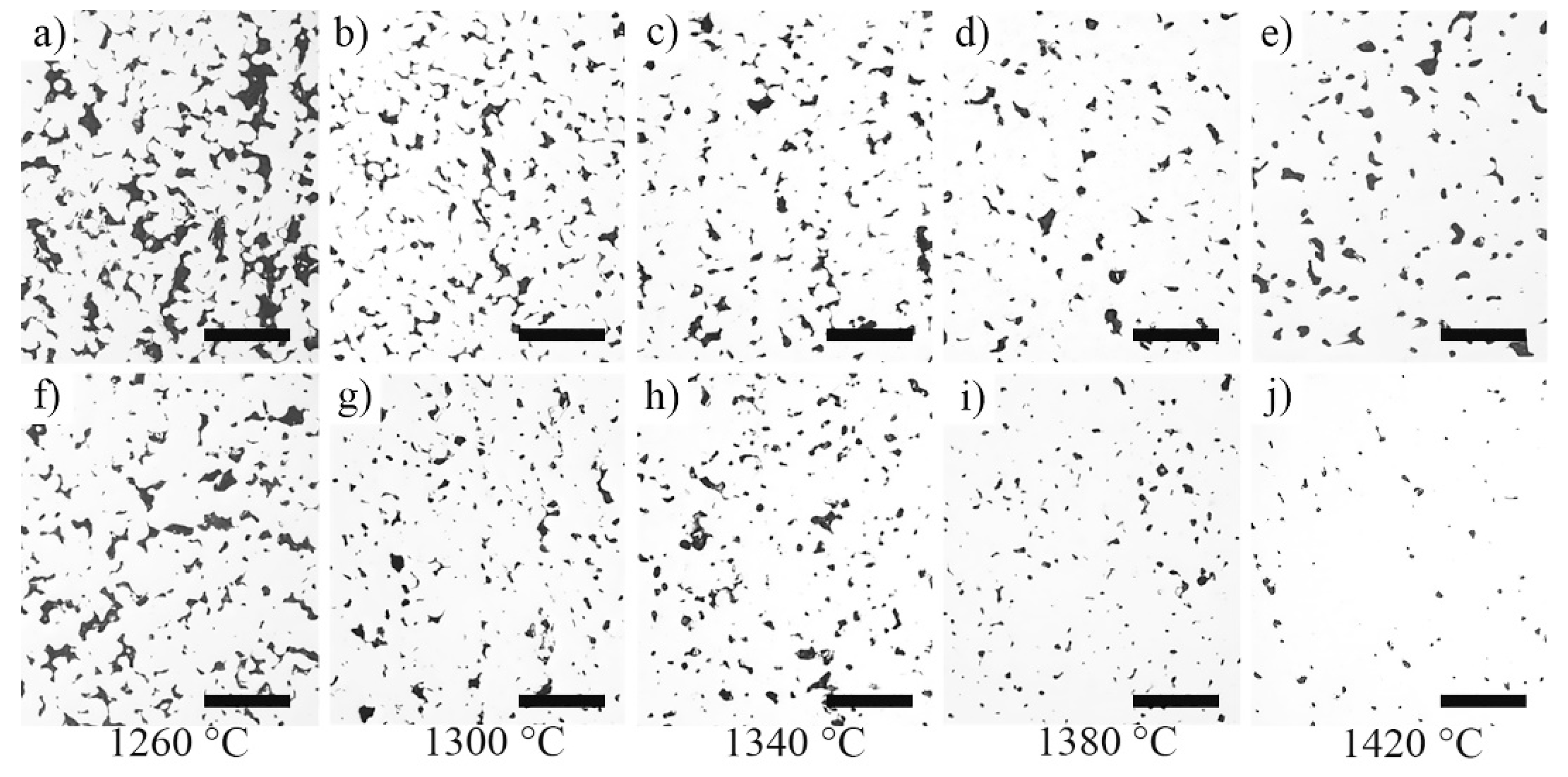
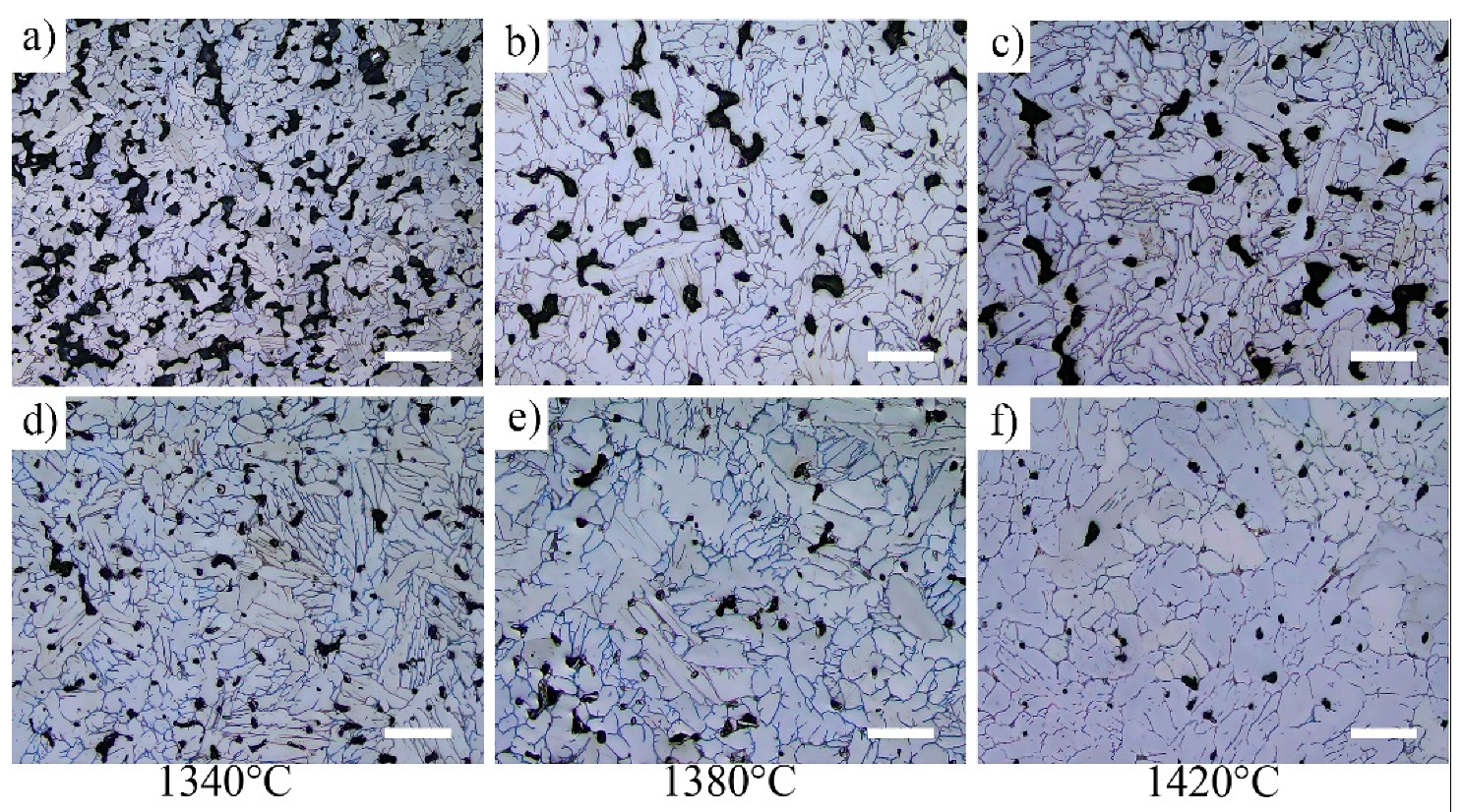
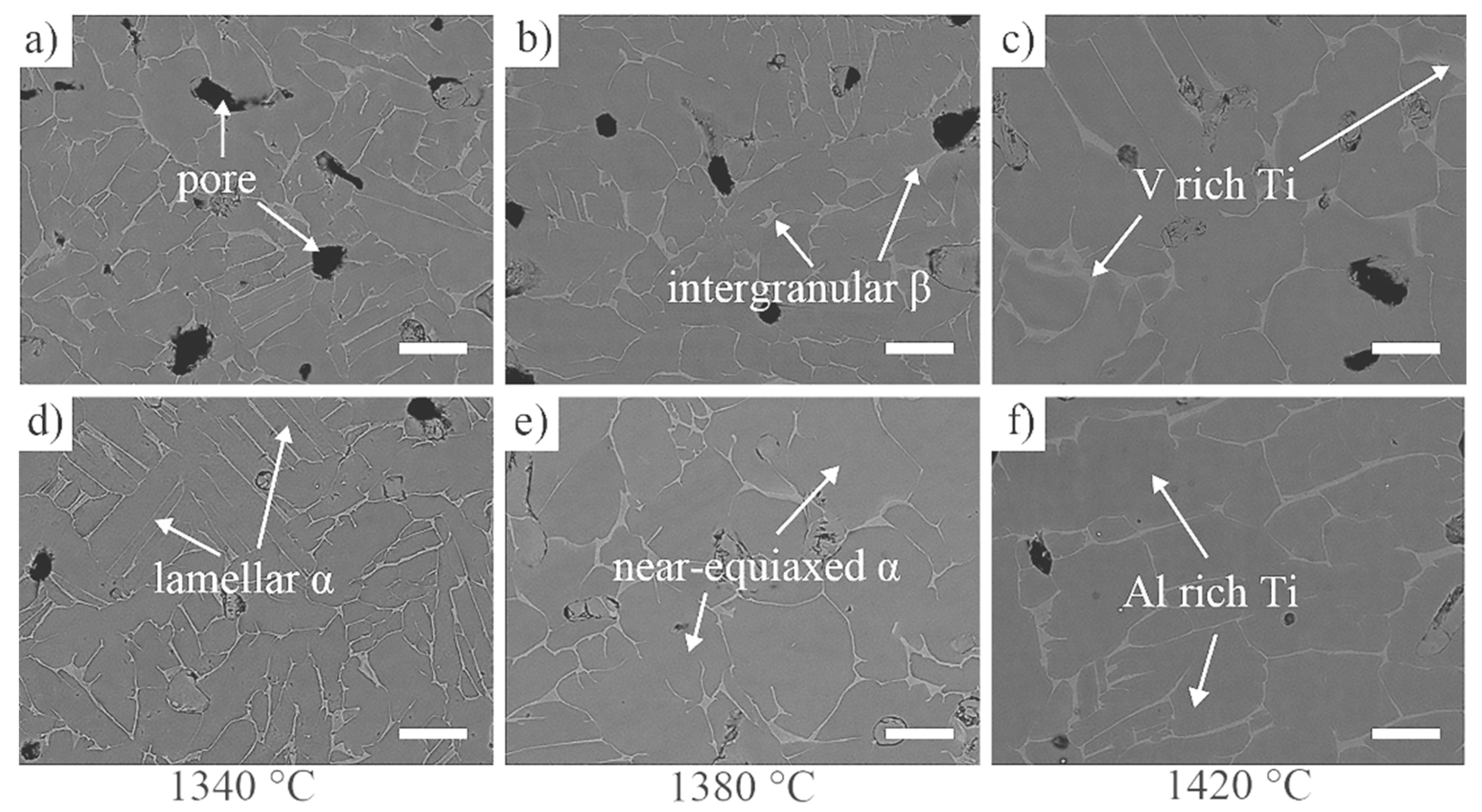
3.4. Microstructure of the Sintered Samples

The microstructure of samples sintered at higher sintering temperatures is further studied as shown in Figure 9. The microstructure of sintered samples mainly presents lamellar and near-equiaxed structure with additional presence of pores. The lamellar structures have different orientations. The grain size of the sintered samples with pure and mixed powder increases with the increase of the sintering temperature. At the same sintering temperature, the grain size of the sintered samples is larger by mixing fine powder. As the temperature increased to 1420 °C, the lamellar structures of the mixed powder sintered samples decreased, the size of the near-equiaxed structures increased, and the average grain size was measured as 76.88 μm. Analysis considers that the precipitation and recrystallization of powder mainly occur at the particle boundary. Meanwhile, the larger specific surface area and particle boundary size of fine powder promote the nucleation of recrystallization. In addition, the β-phase grains have sufficient driving force to engulf and coarsen each other after sintering at a higher temperature, resulting in a larger grain size.

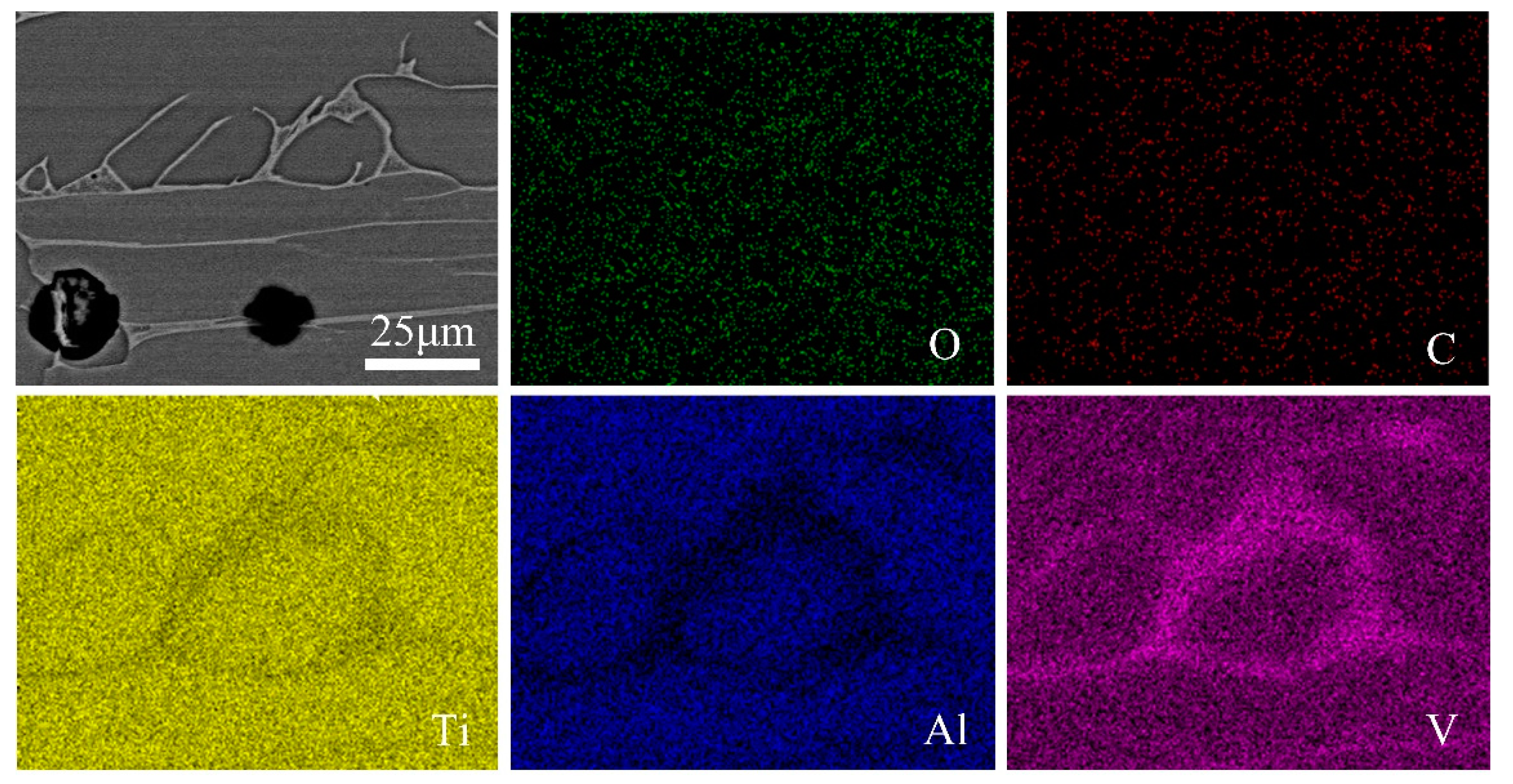
3.5. Electron Microscopy and Elemental Analysis

Figure 10 shows the backscattering electron micrographs of sintered samples. EDS mapping of the sample with mixed powder sintered at 1420 °C is shown in Figure 11. The results indicated that Ti6Al4V alloys consist of the solid solution region with a dark gray color for Al-rich matrix and the interdendritic eutectic with a light gray color for V-rich precipitates. The Al is better distributed than the V due to the full melting and spreading of Al at lower temperatures. In addition, the mixing of fine powder has no significant effect on the element distribution and morphology of the samples.

3.6. Phase Analysis by XRD

Figure 12 illustrates the XRD patterns of original powder and the samples sintered at different temperatures. The results show that Ti phase exists as the main crystalline peaks in the original powder and sintered samples. The difference is that TiC phase can only be observed in sintered samples, caused by the reaction between Ti with residual C from PVP pyrolysis. However, the diffraction peak of TiC is very weak. In addition, it can be observed that the characteristic peak of Ti at 40.5° becomes stronger with the increase of sintering temperature, indicating the increase of crystallinity. The characteristic peak of sintered samples with mixed powder is stronger than that of pure powder.

3.7. Mechanical Properties

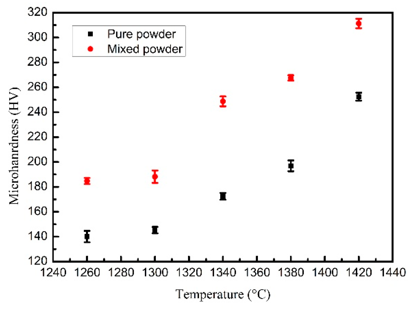
3.7.1. Microhardness

The microhardness measurement results of the sintered samples are shown in Figure 13. The microhardness of samples increases with the increase of sintering temperature, mostly due to the increase of density of samples. The microhardness value of samples sintered with pure powder and mixed powder increases from 141 HV to 255 HV and from 185 HV to 316 HV, respectively. The highest value is close to that reported by Villa et al. [23], who used the pressing method to obtain a Ti6Al4V parts with the microhardness of 353 HV.

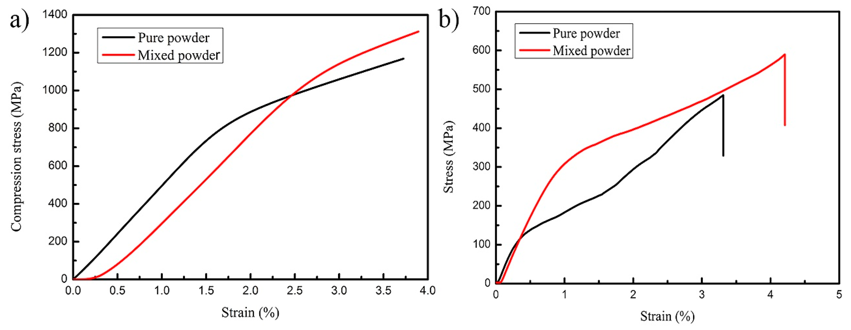
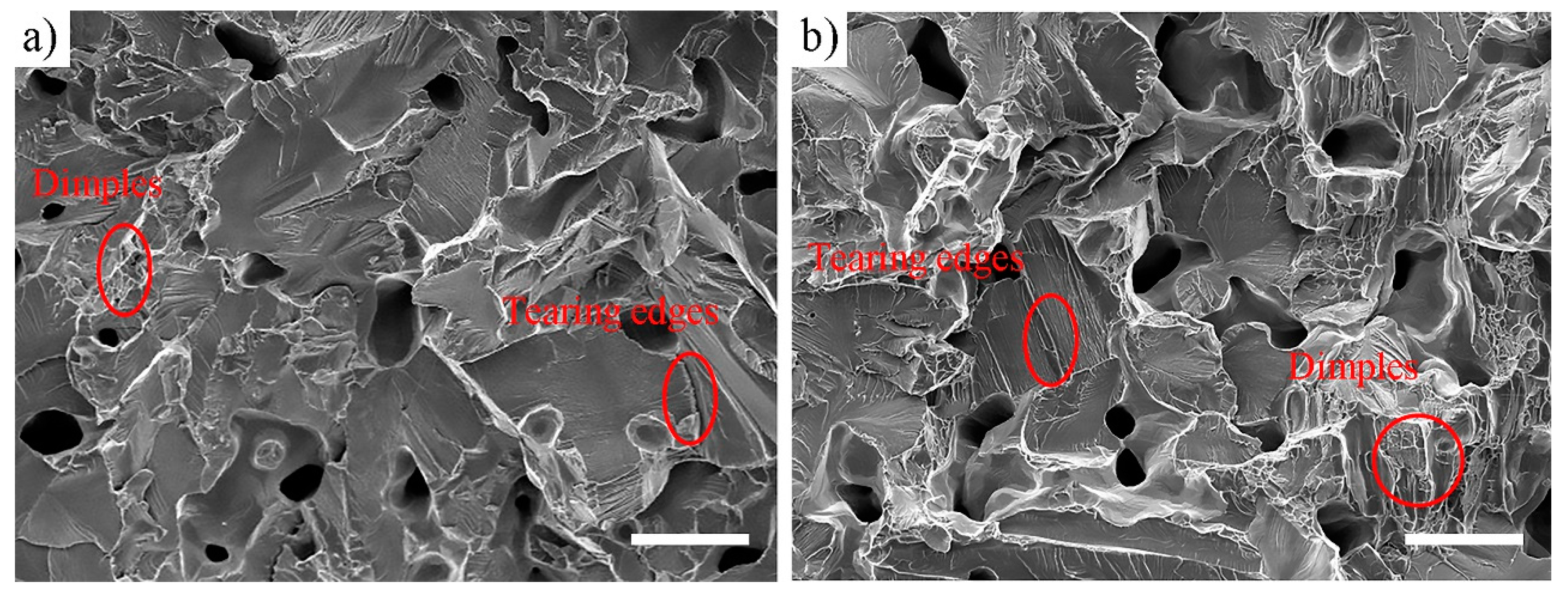
3.7.2. Compression and Tensile Tests

Figure 14 shows the compressive strength and tensile strength of the BJ3DP Ti6Al4V samples sintered at 1420 °C. The compression strain-stress curve (Figure 14a) of the samples can be divided into two stages. The sample displays elastic deformation in the first stage and plastic deformation (deviating from Hooke’s law) in the second stage. The compressive stress value (σ 0.2) is 862 MPa for the pure powder sintered sample, and 1021 MPa for the mixed powder sintered sample. The compressive stress values (σ 0.2) obtained in our work is larger than the value of 753 MPa reported by Villa [23]. In addition, the values are also larger than 825 MPa reported by the standard of titanium alloy casting (ASTM B863-2010).
The tensile strain-stress curve of the samples sintered at 1420 °C is shown in Figure 14b. The yield stress and elongation of the pure powder sintered sample are 475 MPa and 3.26%, respectively, and of the mixed powder sintered sample are 589 MPa and 4.15%, respectively. Analysis considers that the low yield stress is more likely to be due to the uncertainty of sample fracture caused by randomly distributed pores acting as stress concentration. Meanwhile, the formation of grain boundary carbide leads to the reduction of ductility. SEM micrographs of the fracture surfaces illustrated as shown in Figure 15. The fracture surface of the mixed powder sample shows more dimple morphology, and the depth of the dimple is deeper than that of the pure powder sample. In addition, the quasi-cleavage fracture morphology and tear edges can be observed. These quasi-cleavage fractures indicate the sign of poor plasticity of the sample.

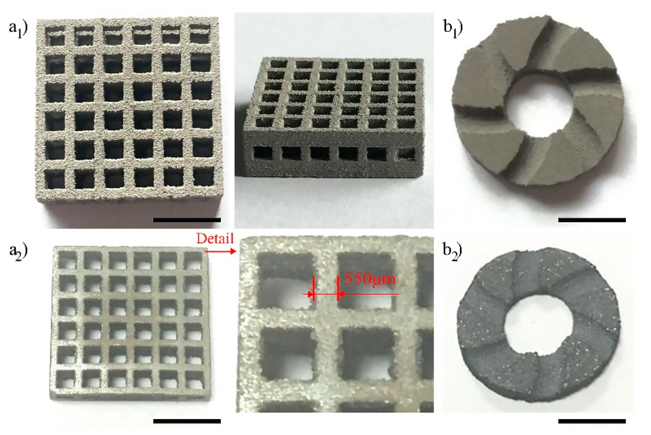
3.8. Lightweight Porous and Curved Structure for Ti6Al4V by BJ3DP

Figure 16(a1,b1) to Figure 16(a2,b2) shows the optical image of the printed Ti6Al4V parts with mixed powder before sintering and after sintering at 1420 °C for 2 h in a vacuum, respectively. It can be observed that the printed Ti6Al4V parts present the capabilities of BJ3DP of complex parts for lightweight porous and curved structure. In addition, the images demonstrate that the Ti6Al4V parts maintain the printed shape well after sintering. The detail size of the porous structure is measured to be 550 μm, which fully demonstrates the great potential of BJ3DP in the printing of fine structure in Ti6Al4V parts.

4. Conclusions

In this study, the thermal-bubble inkjet (TIJ) printhead was used to eject binder ink due to its lower cost, higher nozzle density and higher print speed compared to piezoelectric inkjet (PIJ). In addition, using a low concentration in-situ polymer binder offers an environmentally friendly and low-cost method for inkjet printing Ti6Al4V. Meanwhile, a new process pathway for mixing fine powders was used to fabricate Ti6Al4V parts with excellent properties. More importantly, the effects of mixed powder on the formation process of capillary force and the performance of the green body was analyzed by theoretical models and experiments. Furthermore, a reasonable process of sintering was used to improve the density of the Ti6Al4V parts. As expected, the capillary pressure was enhanced from 8.35 kPa to 16.27 kPa after mixing with fine powder. The compression strength of the green body was enhanced from 1.5 MPa to 3.21 MPa. After sintering, the densification of samples is dependent on the initial coordination number and sintering temperature. The results show that the sintered sample with mixed powder at 1420 °C for 2 h has achieved a maximum density of 95.2%, linear shrinkage of 13.4%, and microhardness of 316 HV, compression strength of 1021 MPa, yield stress of 589 MPa, and elongation of 4.15%. The mixing of fine powder has no significant effect on the element distribution and morphology of the sample. Phase analysis shows that the crystallinity of sintered samples can be improved by mixing fine powder. Finally, a porous structure with detail size of 550 μm and curved complex structure were manufactured. The present work has established the experiment and theoretical foundation for using BJ3DP in manufacturing of Ti6Al4V parts.
These results might provide new clues to better understand metal manufacturing by BJ3DP technology and new applications of Ti6Al4V parts. In addition, it is also valuable for the further research on fabrication of other metals. Although the Ti6Al4V parts fabricated by BJ3DP technique are still not fully dense, the density of nearly 95% can meet the requirements of light load. We believe that BJ3DP technology can be used to fabricate Ti alloy parts with higher density as well as complicated lightweight structures.

Author Contributions

Conceptualization, methodology, validation, data curation and writing—original draft preparation, Y.T.; formal analysis and investigation, Y.T. and Z.H.; writing—review and editing, Y.T., Z.H., and J.Y.; supervision, project administration and funding acquisition, Y.X.; All authors have read and agreed to the published version of the manuscript.

Funding

This research was funded by the Research and Development of Inkjet Technology and Nozzle Devices (NO. Y8AAM11001), and Joint R&D Laboratory of Inkjet Printing and 3D Printing (NO. 1119001002).

Acknowledgments

We would like to thank the support of Suzhou Institute of Nano-tech and Nano-bionics.

Conflicts of Interest

The authors declare no conflict of interest.

References

  1. Kumar, A.Y.; Wang, J.; Bai, Y.; Huxtable, S.T.; William, C.B. Impacts of process-induced porosity on material properties of copper made by binder jetting additive manufacturing. Mater. Des. 2019, 182, 108001. [Google Scholar] [CrossRef]
  2. Enneti, R.K.; Prough, K.C.; Wolfe, T.A.; Klein, A.; Studley, N.; Trasorras, J.L. Sintering of WC-12%Co processed by binder jet 3D printing (BJ3DP) technology. Int. J. Refract. Met. Hard Mater. 2018, 71, 28–35. [Google Scholar] [CrossRef]
  3. Bai, Y.; Williams, C.B. The effect of inkjetted nanoparticles on metal part properties in binder jetting additive manufacturing. Nanotechnology 2018, 29, 39. [Google Scholar] [CrossRef] [PubMed]
  4. Mostafaei, A.; De Vecchis, P.R.; Buckenmeyer, M.J.; Wasule, S.R.; Brown, B.N.; Chmielus, M. Microstructural evolution and resulting properties of differently sintered and heat-treated binder-jet 3D-printed Stellite 6. Mater. Sci. Eng. C 2019, 102, 276–288. [Google Scholar] [CrossRef]
  5. Salehi, M.; Maleksaeedi, S.; Nai, S.M.L.; Meenashisundaram, G.K.; Goh, M.H.; Gupta, M. A paradigm shift towards compositionally zero-sum binderless 3D printing of magnesium alloys via capillary-mediated bridging. Acta Mater. 2019, 165, 294–306. [Google Scholar] [CrossRef]
  6. Nandwana, P.; Elliott, A.M.; Siddel, D.; Merriman, A.; Peter, W.H.; Babu, S.S. Powder bed binder jet 3D printing of Inconel 718: Densification, microstructural evolution and challenges. Curr. Opin. Solid State Mater. Sci. 2017, 21, 207–218. [Google Scholar] [CrossRef]
  7. Mostafaei, A.; Vecchis, P.R.D.; Nettleship, I.; Chmielus, M. Effect of powder size distribution on densification and microstructural evolution of binder-jet 3D-printed alloy 625. Mater. Des. 2019, 162, 375–383. [Google Scholar] [CrossRef]
  8. Mostafaei, A.; Stevens, E.L.; Hughes, E.T.; Biery, S.D.; Hilla, C.; Chmielus, M. Powder bed binder jet printed alloy 625: Densification, microstructure and mechanical properties. Mater. Des. 2016, 108, 126–135. [Google Scholar] [CrossRef] [Green Version]
  9. Elsayed, H.; Rebesan, P.; Giacomello, G.; Pasetto, M.; Gardin, C.; Ferroni, L.; Zavan, B.; Biasetto, L. Direct ink writing of porous titanium (Ti6Al4V) lattice structures. Mater. Sci. Eng. C 2019, 103, 109794. [Google Scholar] [CrossRef]
  10. Geetha, M.; Singh, A.K.; Asokamani, R.; Gogia, A.K. Ti based biomaterials, the ultimate choice for orthopaedic implantsea review. Progess Mater. Sci. 2009, 54, 397–425. [Google Scholar] [CrossRef]
  11. Meenashisundaram, G.K.; Wang, N.Y.; Maskomani, S.; Lu, S.L.; Anantharajan, S.K.; Dheen, S.T.; Nai, S.M.L.; Fuh, J.Y.H. Fabrication of Ti + Mg composites by three-dimensional printing of porous Ti and subsequent pressureless infiltration of biodegradable Mg. Mater. Sci. Eng. C 2020, 108, 110478. [Google Scholar] [CrossRef] [PubMed]
  12. Barui, S.; Chatterjee, S.; Mandal, S.; Kumar, A.; Basu, B. Microstructure and compression properties of 3D powder printed Ti-6Al-4V scaffolds with designed porosity: Experimental and computational analysis. Mater. Sci. Eng. C 2017, 70, 812–823. [Google Scholar] [CrossRef] [PubMed]
  13. Barui, S.; Panda, A.K.; Naskar, S.; Kuppuraj, R.; Basu, S.; Basu, B. 3D inkjet printing of biomaterials with strength reliability and cytocompatibility: Quantitative process strategy for Ti-6Al-4V. Biomaterials 2019, 213, 119212. [Google Scholar] [CrossRef] [PubMed]
  14. El-Hajje, A.; Kolos, E.C.; Wang, J.K.; Maleksaeedi, S.; He, Z.M.; Wiria, F.E.; Choong, C.; Ruys, A.J. Physical and mechanical characterisation of 3D-printed porous titanium for biomedical applications. Mater. Med. 2014, 25, 2471–2480. [Google Scholar] [CrossRef] [PubMed]
  15. Wiria, F.E.; Shyan, J.Y.M.; Lim, P.N.; Wen, F.G.C.; Yeo, J.F.; Cao, T. Printing of Titanium implant prototype. Mater. Design 2010, 31, S101–S105. [Google Scholar] [CrossRef]
  16. Stevens, E.; Schloder, S.; Bono, E.; Schmidt, D.; Chmielus, M. Density variation in binder jetting 3D-printed and sintered Ti-6Al-4V. Addit. Manuf. 2018, 22, 746–752. [Google Scholar] [CrossRef]
  17. Wang, Y.; Bolkor, J. Ultra-high-resolution monolithic thermal bubble inkjet print head. J. Micro-Nanolithogr. Mem. 2007, 6, 043009. [Google Scholar]
  18. German, R.M. Prediction of sintered density for bimodal powder mixtures. Metall. Trans. A 1992, 23, 1455–1465. [Google Scholar] [CrossRef]
  19. ASTM Standards. Standard Test Methods for Tension Testing of Metallic Materials; ASTM Internation: West Conshohocken, PA, USA, 2008. [Google Scholar]
  20. ASTM Standards. Standard Test Methods of Compression Testing of Metallic Materials at Room Temperature; ASTM Internation: West Conshohocken, PA, USA, 2008. [Google Scholar]
  21. Washburn, E.W. The dynamics of capillary flow. Phys. Rev. 1921, 17, 273–283. [Google Scholar] [CrossRef]
  22. Scheel, M.; Seemann, R.; Brinkmann, M.; Di Michiel, M.; Sheppard, A.; Breidenbach, B.; Herminghaus, S. Morphological clues to wet granular pile stability. Nat. Mater. 2008, 7, 189–193. [Google Scholar] [CrossRef]
  23. Cabezas-Villa, J.L.; Lemus-Ruiz, J.; Bouvard, D.; Jiménez, O.; Vergara-Hernández, H.J.; Olmos, L. Sintering study of Ti6Al4V powders with different particle sizes and their mechanical properties. Int. J. Miner. Metall. Mater. 2018, 25, 1389–1401. [Google Scholar] [CrossRef]
  24. Cai, C.; Song, B.; Xue, P.J.; Wei, Q.S.; Wu, J.M.; Li, W.; Shi, Y.S. Effect of hot isostatic pressing procedure on performance of Ti6Al4V: Surface qualities, microstructure and mechanical properties. J. Alloy. Compd. 2016, 686, 55–63. [Google Scholar] [CrossRef]
  25. German, R.M. Coordination number changes during powder densification. Powder Technol. 2014, 253, 368–376. [Google Scholar] [CrossRef]
Figure 1. Properties of the Ti6Al4V powder; (a) the particle size distribution of original powder, (b) the microstructure of the pure powder, (c) the microstructure of mixed powder. Scale bar = 50 μm.
Metals 10 01354 g001
Figure 2. Principle of capillary infiltration forming of polymer binder, (a) binder droplets were selectively deposited into the powder bed, (b) binder solution spreads in the powder bed, (c) binder solution infiltrates in the powder bed, (d) curing film and bridge are formed after heating.
Metals 10 01354 g002
Figure 3. The contact angles of droplets on the surfaces of pure and mixed powders were measured. (a) The droplet of binder on the surface of pure powder; (b) the droplet of binder on the surface of mixed powder.
Metals 10 01354 g003
Figure 4. Stress-strain curves obtained from the binder jet 3D printing (BJ3DP) Ti6Al4V green bodies.
Metals 10 01354 g004
Figure 5. The establishment of the theoretical model and the characterization of the SEM to assist in understanding BJ3DP. A model for the single structure of the curing bridge (a) and SEM of sample (b); a model for the staggered structure of the curing bridge (c) and SEM of sample (d); SEM of the sample with pure powder (e) and mixed powder (f).
Metals 10 01354 g005
Figure 6. The appearance morphology of sintered samples with pure powder (af) and mixed powder (gl) at different sintering temperatures. Scale bar = 1 cm.
Metals 10 01354 g006
Figure 7. The relative density (a) and shrinkage (b) of the sintered samples at different sintering temperatures.
Metals 10 01354 g007
Figure 8. Optical micrographs of polished sintered samples at different temperatures: (ae) pure powder; (fj) mixed powder. Scale bar = 200 μm.
Metals 10 01354 g008
Figure 9. Microstructures of the sintered samples sintered with pure powder and mixed powder at different temperatures: (ac) pure powder; (df) mixed powder. Scale bar = 100 μm.
Metals 10 01354 g009
Figure 10. The backscattering electron micrographs imaging of different sintered samples: (ac) pure powder; (df) mixed powder. Scale bar = 25 μm.
Metals 10 01354 g010
Figure 11. Scanning electron micrographs with EDS mapping elemental analysis of the mixed powder samples sintered at 1420 °C.
Metals 10 01354 g011
Figure 12. The XRD patterns of original powder and the samples sintered at different temperatures: (a) the pure powder, (b) the mixed powder.
Metals 10 01354 g012
Figure 13. Microhardness of Ti6Al4V parts sintered with pure powder and mixed powder.
Metals 10 01354 g013
Figure 14. The stress-strain curves of BJ3DP Ti6Al4V samples: (a) the compression strain-stress curve; (b) the tensile strain-stress curve.
Metals 10 01354 g014
Figure 15. SEM micrographs of the fracture surface of BJ3DP Ti6Al4V samples sintered with pure powder (a) and mixed powder (b). Scale bar = 50 μm.
Metals 10 01354 g015
Figure 16. The optical images of Ti6Al4V parts with lightweight porous (a1,a2) and curved structure (b1,a2): before sintering (a1,b1) and after sintering (a2,b2). Scale bar = 0.5 cm.
Metals 10 01354 g016
Table 1. Powder composition.
Particle Size (μm)Ti (wt%)Al (wt%)V (wt%)C (wt%)O (wt%)N (wt%)
15–53Bal3.825.830.0230.0960.018
0–20Bal3.825.830.0230.1280.018
Table 2. Image analysis results on micrographs (shown in Figure 8) obtained from the sintered samples at different sintering temperatures.
Sample DescriptionSintering Temperature (°C)Solid Volume Fraction (%)Porosity (%)Maximum Pore Size (μm)
Pure powder1260 °C82.0 ± 3.118.0 ± 3.8188.5 ± 8.9
Pure powder1300 °C86.4 ± 1.613.6 ± 1.2147.1 ± 5.7
Pure powder1340 °C89.5 ± 1.310.5 ± 2.1132.8 ± 6.1
Pure powder1380 °C91.6 ± 1.18.4 ± 0.8112.1 ± 5.4
Pure powder1420 °C93.2 ± 0.86.8 ± 0.7117.2 ± 4.9
Mixed powder1260 °C90.5 ± 2.19.5 ± 2.0128.7 ± 6.2
Mixed powder1300 °C92.2 ± 1.87.8 ± 1.5109.7 ± 5.8
Mixed powder1340 °C93.8 ± 1.36.2 ± 0.592.5 ± 5.0
Mixed powder1380 °C94.9 ± 0.95.1 ± 1.062.5 ± 4.6
Mixed powder1420 °C97.1 ± 0.62.9 ± 0.235.1 ± 3.3

