Article

Residual Stresses and Surface Roughness Analysis of Truncated Cones of Steel Sheet Made by Single Point Incremental Forming

1
Institute of Technology and Material Engineering, Faculty of Mechanical Engineering, Technical University of Košice, Mäsiarska 74, 04001 Košice, Slovakia
2
Department of Mechanical Engineering, State School of Higher Vocational Education, Rynek 1, 38-400 Krosno, Poland
3
Department of Manufacturing and Production Engineering, Rzeszow University of Technology, al. Powst. Warszawy 8, 35-959 Rzeszów, Poland
4
Department of Materials Forming and Processing, Rzeszow University of Technology, al. Powst. Warszawy 8, 35-959 Rzeszów, Poland
5
Centre for Innovative Technologies, University of Rzeszów, ul. Pigonia 1, 35-959 Rzeszów, Poland
6
Institute of Technology, Faculty of Mathematics and Natural Sciences, University of Rzeszów, al. Rejtana 16c, 35-959 Rzeszow, Poland
7
Department of Machining and Manufacturing Technology, University of Žilina, Univerzitna 1, 010-26 Žilina, Slovakia
*
Author to whom correspondence should be addressed.
Metals 2020, 10(2), 237; https://doi.org/10.3390/met10020237
Submission received: 31 December 2019 / Revised: 5 February 2020 / Accepted: 7 February 2020 / Published: 10 February 2020
(This article belongs to the Special Issue Forming Processes of Modern Metallic Materials)

Abstract

:
The dimensional accuracy and mechanical properties of metal components formed by the Single Point Incremental Forming (SPIF) process are greatly affected by the prevailing state of residual stress. An X-ray diffraction method has been applied to achieve an understanding of the residual stress formation caused by the SPIF process of deep drawing a quality steel sheet drawpiece. The test object for an analysis of residual stress distribution was a conical truncated drawpiece with a slope angle of 71° and base diameter of the cone of 65 mm. The forming process has been carried out on a 3-axis HAAS TM1P milling machine. Uniaxial tensile tests have been carried out in the universal tensile testing machine to characterize the material tested. It was found that the inner surface of the drawpiece revealed small linear grooves as a result of the interaction of the tool tip with the workpiece. By contrast, the outer surface was free of grooves which are a source of premature cracking. The stress profile exhibits a nonlinear distribution due to different strengthening of the material along the generating line of the truncated conical drawpiece. The SPIF parts experienced a maximum residual stress value of about 84.5 MPa.

1. Introduction

Single Point Incremental Forming (SPIF) is a sheet metal forming process which involves forming by local stretching of the sheet with a pin tool. The tool moves along a path controlled by a computer numerical control (CNC) machine. Incremental Sheet Forming (ISF) allows the forming of complex parts with a much higher degree of deformation than conventional deep drawing or stretch forming processes [1,2].
Springback is one of the main problems associated with incremental forming processes. The amount of springback is affected by the geometry of the drawpiece, the mechanical properties of the sheet material and the tension applied [3]. In SPIF, the state of residual stress can be influenced by adjusting the process parameters during the machining process [4]. A literature review of SPIF suggests that the geometrical accuracy of drawpieces may be increased by using a smaller tool diameter, a smaller tool step-down, and thicker sheets [5,6]. The large levels of deformation occurring in SPIF induce highly non-uniform residual stresses that affect the shape and dimensional accuracy of the formed parts.
Analysis of surface topography in ISF has gained research interest in the past few years [7,8]. According to Lasunon et al. [9] feed rate has little effect on the surface roughness, while the wall angle, depth increment, and its interaction play an important role. Hagan and Jeswiet [10] analyzed the effect of several forming variables, such as step-down size and spindle speed, on surface roughness. They concluded that the surface finish is a resultant of large-scale waviness created by the tool path and small-scale roughness induced by large surface strains. Attanasio et al. [11] investigated effect of variable step size and constant step size on surface roughness. It was found that varying step size with constant scallop height produced better surface finish. Powers et al. [12] found that the maximum height of the profile Rz is greater with rolling marks perpendicular to forming orientation. The surface roughness increases with the post-forming sheet strength, forming force, and residual stress, thereby showing that strain hardening has a direct influence on the roughness [13]. Furthermore, Al-Ghamdi and Hussain [13] found that the free-surface roughness and the contact-surface roughness are inversely related. Durante et al. [14] investigated the effect of spindle speed on the average surface of pyramid frusta. Roughness of surface was found to decrease when spindle speed passed from not rotating to rotating conditions. A detailed review of the current state-of-the-art of ISF processes in terms of its technological capabilities and discussions on the ISF process parameters and their effects on ISF processes may be found in the works of Gatea et al. [15] and Behera et al. [8]. Maqbool and Bambach [16] quantified the respective contribution of each forming mechanism (i.e., bending, membrane stretching, through-thickness shear) involved in the SPIF process and the dependence of geometrical accuracy on the dominant deformation mechanism. The practical consequence of the mode of deformation on the geometrical accuracy of pyramid-shaped parts has been demonstrated. It was found that a decrease in the dissipation energy in the bending mode leads to lower residual moments.
Residual stresses are defined as the internal stresses in a material that are present in the absence of external loading. In ISF the residual stresses are mainly caused due to local yielding of the material as a consequence of its plastic deformation. The lifetime and integrity of the components are greatly affected by the intensity of residual stresses [17]. The residual stresses also affect the fatigue life of the protective coatings which is especially important in the case of the low-carbon deep-drawing quality steel sheets used in the automotive industry. The combination of tensile residual stresses with service stresses adversely affects the fatigue life of the components, whereas compressive residual stresses are beneficial in improving the fatigue life of formed components [17,18,19]. An increase in the geometrical accuracy is achieved due to the decreased contribution of the bending deformation mode and lower residual moment [16]. A better understanding of the residual stresses is necessary to increase the geometrical accuracy of incrementally formed parts.
In the last decade, many papers have been devoted to residual stress analysis in incremental forming. There are various methods for measuring residual stresses such as hole drilling [20,21], slitting [22], the contour method [23], and numerical computations [4,17,20]. Maaß et al. [4] analyzed the significance of kinematic hardening effects on the state of residual stress based on numerical simulations. They found that the average deviation of the residual stress amplitudes in the clamped and unclamped parts may reach 18%. The results of numerical computations made by Tanaka et al. [24] revealed that the smaller the radius of the forming stylus, the larger the residual stresses become. Radu et al. [20] inspect, experimentally and by finite element-based simulation, the state of the residual stresses induced in incrementally formed double frustums of pyramids made from 1050 aluminium-based alloy. The hole drilling strain gauge method has been used to find the distribution of residual stresses in the sheet thickness. The results indicated compressive residual stresses with a magnitude that varies through the sheet thickness. In another paper, Radu et al. [25] investigated the effect of residual stresses on the accuracy of parts processed by SPIF using the strain-rosette method. The results of the investigations revealed that a favorable state of residual stresses, and implicitly a good accuracy of parts, can be obtained when small values of tool diameter and vertical step sizes are used. Shi et al. [21] investigated the residual stresses in incrementally formed Cu/steel bonded laminates using the hole-drilling method. They found that the most significant process parameters influenced by residual stresses were the tool diameter and wall angle, while the tool rotation was the least significant process parameter. Different unidirectional and bidirectional tool path strategies were used by Maaß et al. [26] to analyze the residual stress development in SPIF formed parts. The results suggest that the influence of the tool path strategy on the amplitude of the resulting residual stress is not decisive. Abdulrazaq et al. [27] used three types of tool shape in their work on the forming of pyramid like drawpieces from 1050 aluminium alloy which gave higher residual stresses than other types. It has been found that residual stresses increased with increasing step size and feed rate values. Al-Ghamdi and Hussain [28] experimentally analyzed the through-thickness stress gradient across the thickness of Cu/steel bonded laminates. It was found that ISF induces a gradient in compressive stress gradient, which can be much greater (about 18 times) than that the rolling process induces in the parent laminates while bonding. An experimental and numerical investigation of the influence of process parameters in ISF on residual stresses has been carried out by Maqboll and Bambach [17]. Residual stresses were determined in parallel and perpendicularly to the direction of tool motion at the center of a strip cut from the numerical model in the clamped and unclamped states. The results of the analyses reveal that the most significant parameter in the build-up of residual stress and the reduction of geometrical accuracy is the wall angle. Different strategies that analyze the intensity of the residual stresses and its effects on the accuracy of parts formed have been discussed in the literature [25,29].
Hajavifard et al. [30] used ISF to improve properties of conical annular discs by introduction residual stresses in material. The main mechanism of residual stress generation was the transformation of metastable austenite into martensite under the action of the forming tool. The residual stresses induced by the selective laser melting process on the fabricated AlSi10Mg metallic sheets, as well as those produced during their ISF operation were analyzed by López et al. [31].
To the best of authors’ knowledge, measurement of the residual stresses by the X-ray diffraction (XRD) method in the SPIF process has not so far been reported. So, in the current study, residual stress distribution was investigated in a conical truncated drawpiece formed by the incremental forming process. The residual stresses were measured in the subsurface layer at a depth of about 0.005 mm. Therefore, verification will be carried out of the possible interaction between the value of the residual stress measured in different parts of the conical truncated drawpieces and the roughness parameters measured on the surface of the drawpieces. In this manuscript residual stresses were measured separately in the axial and tangential directions. The experimental investigations to form a conical truncated drawpiece were carried out on a 3-axis TM1P milling machine (HAAS, Oxnard, CA, USA). A Proto iXRD Combo diffractometer (Proto Manufacturing Inc., Taylor, MI, USA) using CrKα radiation was used to determine the distribution of residual stresses.

2. Experimental Methodology

2.1. Material

The experimental forming of conical truncated drawpieces has been carried out for cold rolled DC04 deep drawing quality steel sheet (1.0338 acc. to EN 10130:2009) with a thickness of 0.8 mm supplied by Arcellor-Mittal (Dąbrowa Górnicza, Poland). The DC04 steel sheet is characterized by high ability to deform, weldability and susceptibility to springback. This material is intended for use in forming processes where good strength, rigidity and ductility are required. Typical applications are to be found in the automotive industry, metal furniture and the domestic appliance sector. The results of the element-analysis obtained by optical emission spectroscopy are presented in Table 1.
The basic mechanical properties of the sheet tested (Table 2) were determined in the uniaxial tensile test according to EN ISO 6892-1:2016-09. The mechanical properties of the sheet metal were determined through tensile tests along three directions with respect to the rolling direction: 0°, 45° and 90°. Three specimens were tested for each cut direction and an average value of a specific parameter was determined. The strain hardening parameters (strength coefficient K and strain hardening exponent n) were determined by approximation of the true stress-true strain relationship using the Hollomon equation
σ p = K · ε n
where σp is the yield stress, ε is the true strain.

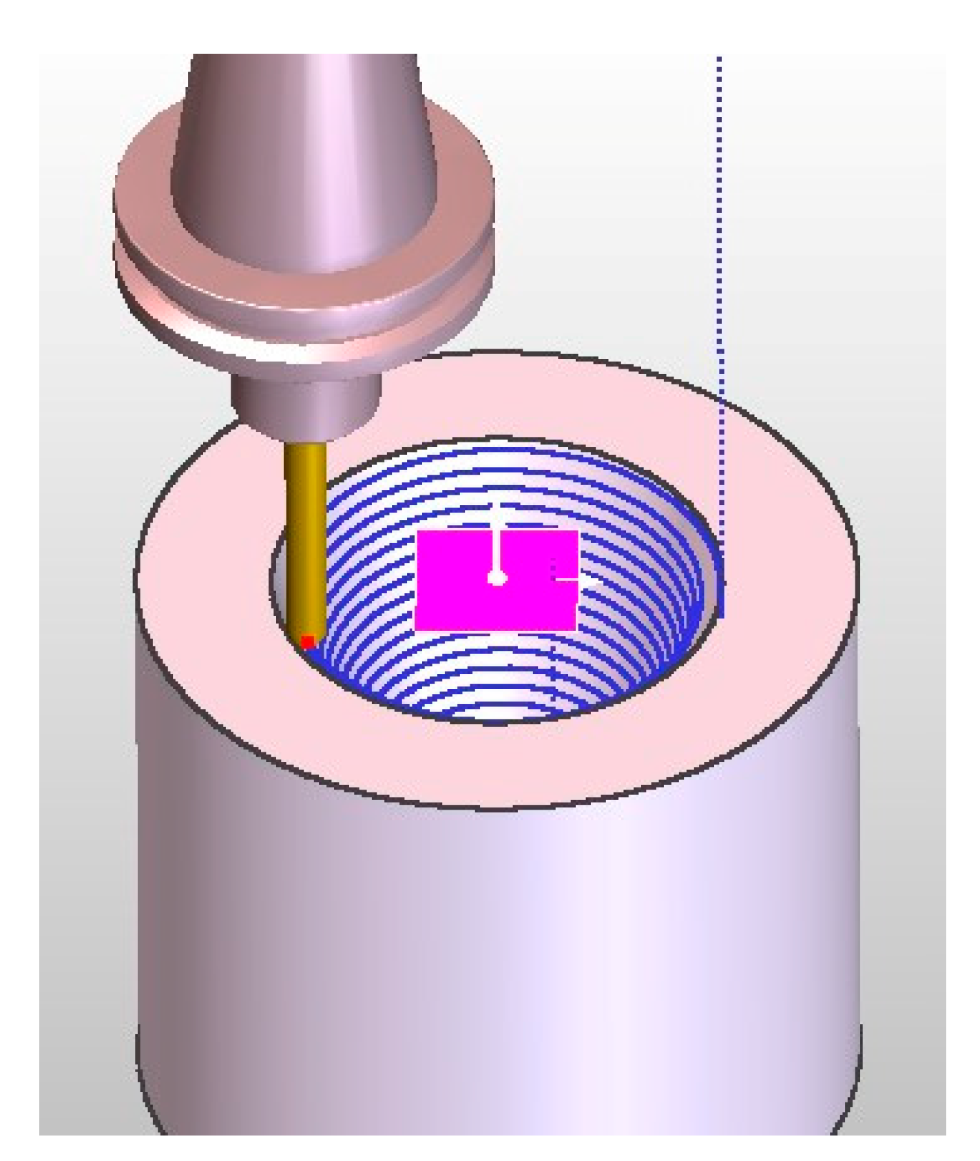
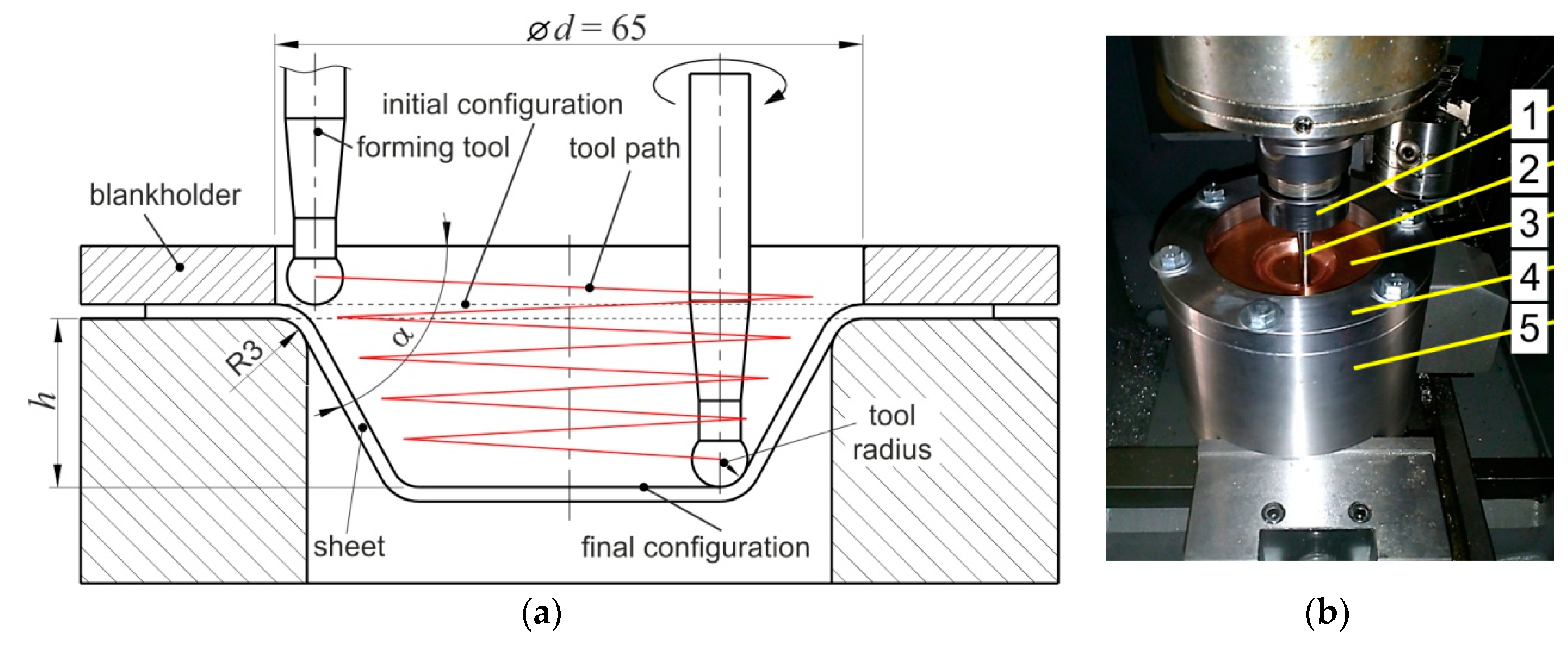
2.2. Incremental Forming

The experimental investigations to form the conical truncated drawpiece (Figure 1a) were carried out on a 3-axis TM1P milling machine (HAAS, Oxnard, CA, USA). Blanks of size 120 mm × 120 mm were placed in the machine, and were clamped at the edges using screws (Figure 1b). The die supports the sheet, and its opening defines the working area of operation of the forming tool. The tool, which is attached in the head of the machine through the ER collet system, continuously indents into the sheet by step size and follows a spiral path for the desired part. The final height drawpiece was equal to 70 mm. The slope angle of the truncated cone and the diameter of the base of the cone were 71° and 65 mm, respectively. The tool was made of high-speed steel and had a rounded tip with a radius R = 3.5 mm and a diameter of 7 mm.
During machining, based on the recent investigations and experience the following processing conditions were applied:
  • − feed rate f = 1500 mm·min–1,
  • − tool rotational speed n = 87 rpm,
  • − incremental depth (step size) ap = 0.3, 0.5 and 0.7 mm,
  • − lubricant: full synthetic 75W-85 (Castrol Ltd., Liverpool, UK) lubricant (viscosity 74.0 mm2/s (at 40 °C), density 874 kg/m3 (at 15 °C), pour point −45 °C).
The tool path (Figure 2) was generated using the EDGECAM software (Hexagon, Reading, UK) based on the 3D model of a conical truncated drawpiece. After the control program was created, the forming device and tool were mounted on the milling machine. The control program, created in the simulation mode, was then validated in the test mode.

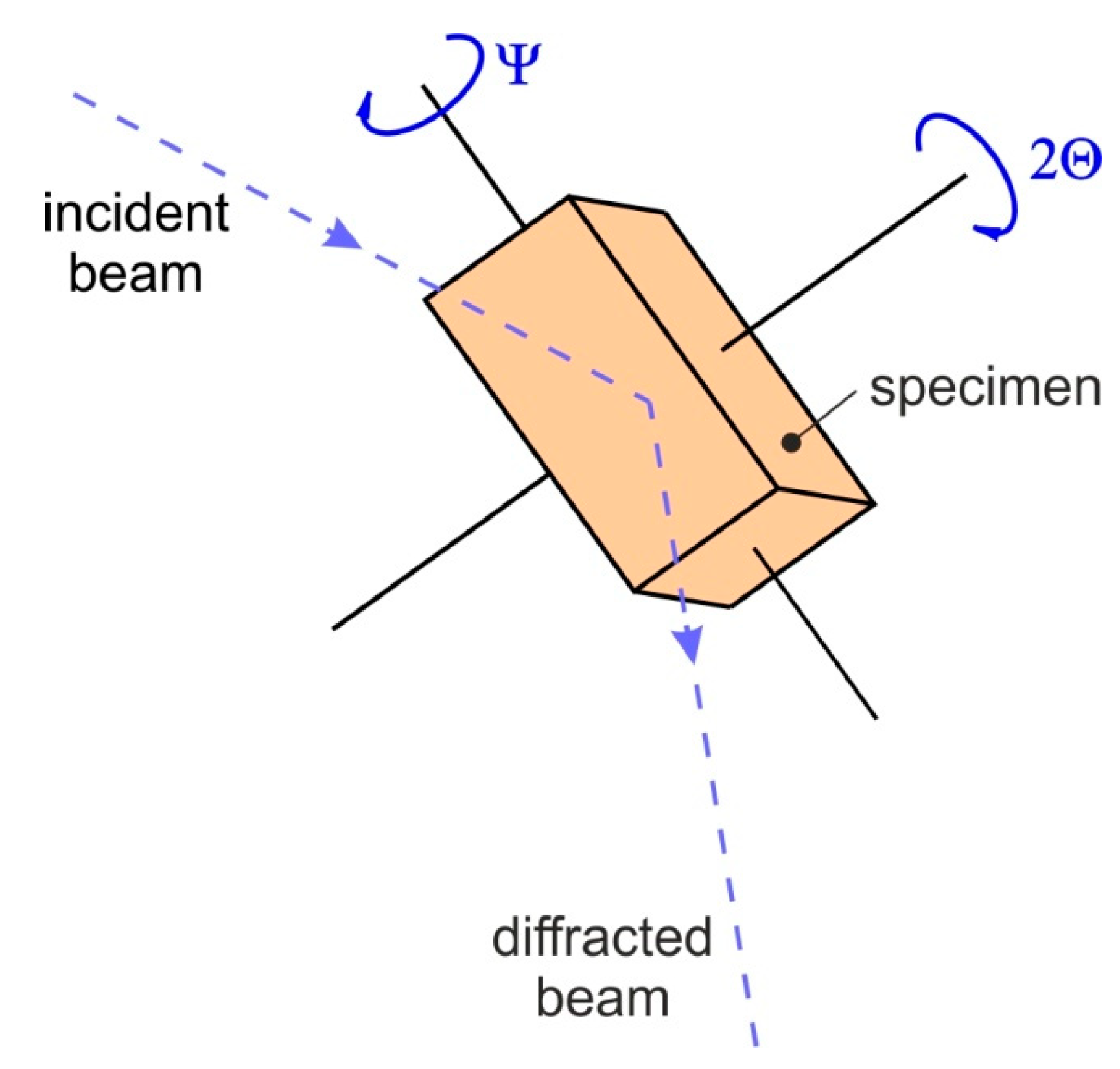
2.3. X-ray Diffraction Analysis

The XRD technique was used to measure the residual stress within the surface layer formed, as a result of interaction between the SPIF tool and the surface of the material being processed. The XRD method is based on the change of position of a diffracted plane which corresponds to a change of the material lattice parameter as a result of material deformation. Residual stresses after unloading were measured by the XRD technique carried out on a Proto iXRD Combo diffractometer (Proto Manufacturing Inc., Taylor, MI, USA) using CrKα radiation (average effective penetration depth ~5 μm, scanning angle ±39° and Bragg angle 156.4°). The residual stresses were calculated from shifts of the 211 reflection. The Winholtz and Cohen method and X-ray elastic constants ½s2 = 5.75 TPa−1, s1 = −1.25 TPa−1 were used for residual stress determination. Residual stresses were measured in the axial as well as the tangential directions in the center of the sample (with respect to their width and length). The strain analysis is based on the interplanar spacing d according to Bragg’s law:
n λ = 2 d ( h k l ) s i n Θ
where λ is the wavelength, Θ is the Bragg angle, n is the diffraction order of the interference (hkl).
The interplanar lattice spacings were measured for different specimen orientations. The residual stress can then be calculated using the sin2ψ method based on the Bragg symmetrical diffraction, and the appropriate elastic material constants. This method uses a Ψ–type goniometer (Proto Manufacturing Inc., Taylor, MI, USA), which allows one to obtain appropriate inclinations of the diffraction vector by angles Ψi (Figure 3) in the plane perpendicular to the diffraction plane. In XRD analyses a round collimator with a diameter of 2 mm was used. The exposure time during which the specimen was overexposed for each diffraction angle was 12 s. The reflection profiles for the were measured in the 2Θ angular range of −39° to 39°. Figure 4 shows the location of the measuring point in the element of the cone.

2.4. Surface Characterisation

Topographies of the as-received and deformed surfaces of truncated cones were characterized by 3D main surface roughness parameters. Measurement of the surface roughness parameters was carried out using a Contour GT 3D optical microscope (Bruker, MA, USA) with vision 64 software. Surface topography was measured at both internal and external surfaces of drawpieces. The main standard 3D parameters determined by this measurement are the average roughness Sa, the highest peak of the surface Sp, the root mean square roughness parameter Sq, and the maximum pit depth Sv. Selection of surface roughness parameters was based on the work of Ham et al. [32,33] which suggested that it was more useful to use areal surface texture parameters in evaluating surface texture and topography in single point incremental sheet forming.
The Sa parameter shows a strong correlation with the Sq parameter. Both the Sa and Sq parameters are used to represent the roughness of a two-dimensional surface topography. Sa describes surface roughness more comprehensively than the arithmetical mean height Ra, the arithmetical mean deviation of the profile that is assessed, which reflects the roughness of a one-dimensional contour [34]. In ISF, the Sa parameter is more suitable for analysis of surface topography than the Ra parameter [35,36].

3. Results and Discussion

3.1. Formability

During the experimental tests truncated cones were made with a slope angle α = 70–72° and with different step size ap, and feed rates. The assumed total depth of the formed part was 75 mm. Two drawpieces were tested for each set of input parameters. The aim of the investigations was to obtain, for all configurations of the input parameters of the forming process, truncated cones with a height of 75 mm. It is noteworthy that a slope angle α in combination with step size ap are responsible for the limit conditions for obtaining the successful deformation of drawpieces without cracks.
The step size ap determines the amount of material that is subjected to deformation during one pass. According to the results of tests carried out, this parameter has little effect on the change of plasticization of the processed material. With an increase in step size ap, a slight increase in the slope angle α was obtained at which the truncated conical drawpiece had a shape that was correct and did not have any defects. The reduction of the ap value caused the drawpieces to crack at the initial stage of forming, in the range of a slope angle of 71–72° (Table 3). The heights of the drawpieces at fracture, shown in Table 3, are the averages of the two drawpieces that are formed. In addition, the reduction in ap results in a longer duration of treatment, which is disadvantageous from the point of economic production. The only positive effect of decreasing the value of the step size is a clear improvement in the quality of the outer and inner surface of the drawpiece (Table 3).
The SPIF of the cones with larger wall angles was limited by their premature fracture (Table 3). It is well known [37], in fact, that at increasing the steepness of the walls, process conditions become heavier, so that plastic collapse occurs in the blank. Obviously, this result is strongly dependent on sheet thinning, which increases at increasing the steepness of the walls. All drawpieces with a slope angle of 72 were fractured at a depth much smaller than the assumed total depth. In contrast the truncated cones with the 70° wall angles were successfully formed until they reached the design depth without fracture. Since at a specific wall angle, a cone can only be successfully formed to a certain depth using single-stage SPIF, the maximum forming angle alone cannot properly represent the formability of the material. Hence, according to Shamsari et al. [38], the formability of a sheet metal in SPIF can be best illustrated by the maximum forming depth at various wall angles, as depicted in Table 3.
Figure 5 shows the deformed parts at fracture. In the case of all the fractured surfaces a fracture occurred as a continuous crack along the circumference of the component. The corner of the drawpiece is the most strained region in the sheet due to its complex stress state. The formability and morphology of crack initiation in the sheet (region of local sheet thinning) is a complex function of the tool path strategy [7,39,40], shape of the drawpiece [15,41], forming temperature [8,15], friction conditions [8,42], and vertical step down [15,38] used. The crack initiation was observed in the vicinity of the rib bottom and propagates along the edge of the truncated cone (Figure 5). The fracture region observed coincides with that seen in the results of the investigations of many authors [38,41]. The drawpieces were fractured due to excessive thinning of the sheet and sharp edges were produced from the crack surface.

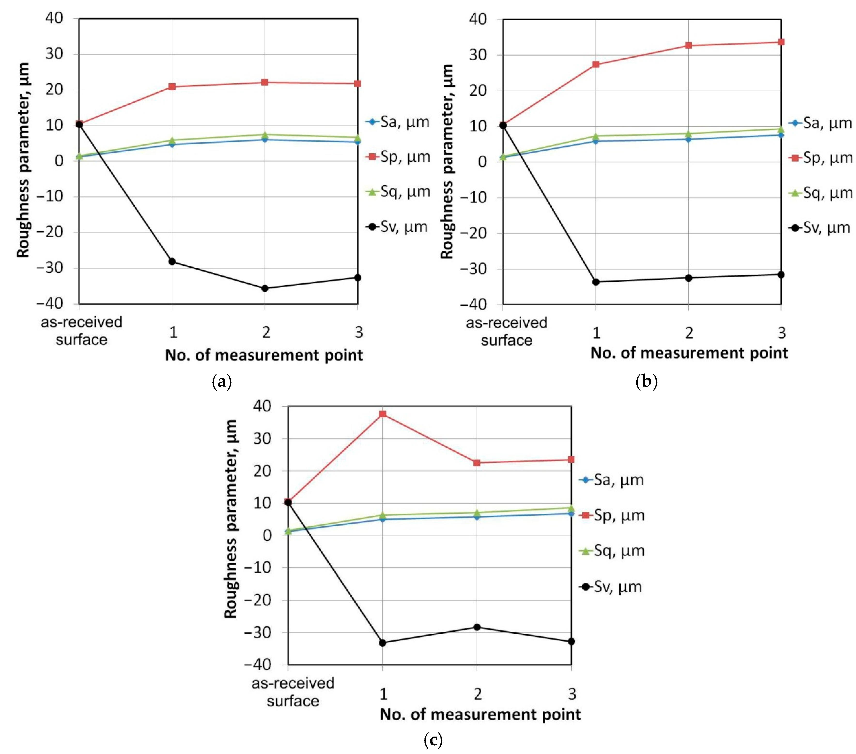
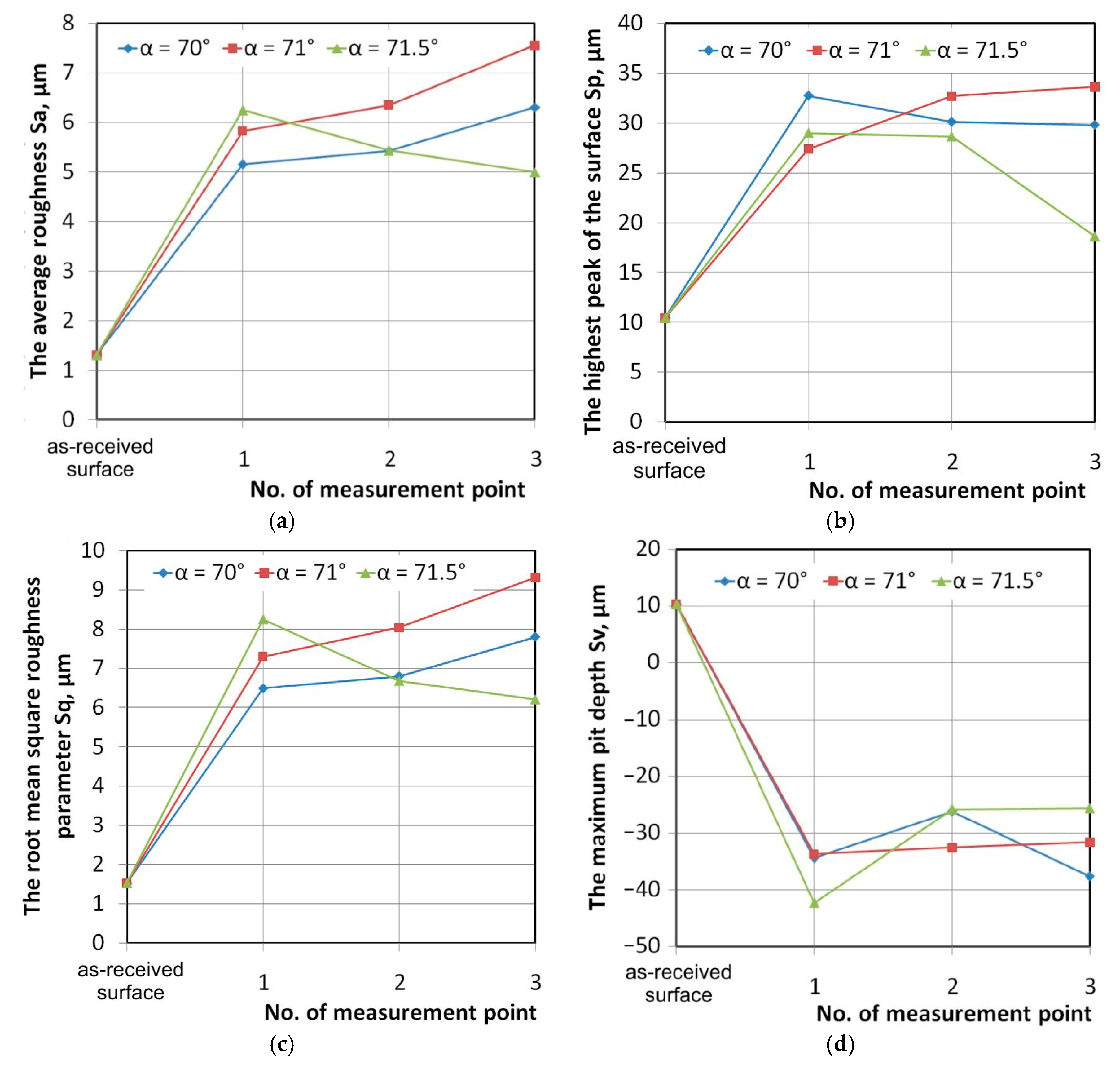
3.2. Surface Roughness

As mentioned above, a slope angle in combination with a step size ap are responsible for obtaining a successful drawpieces without cracks. The step size influences the material deformation limit to a small degree. However, the step size had a very large impact on the surface finish of the surface of the part. Although the small linear scratch bands resulting from the interaction of the tool tip with the workpiece material have been revealed on the inner surface of the drawpiece, no clear grooves have been found on the outer surface. Small areas of galling with a wavy appearance are also visible on the internal surface (Figure 6). In SPIF, the surface finish on the inner surface can be mainly be characterized as a resultant of large-scale waviness created by the forming path [43]. The surface roughness of the outer surface is mainly caused by large surface strains, which usually leads to an orange peel phenomenon (Figure 6).
Figure 7 and Figure 8 show the surface topographies of the outer (Figure 7) and inner (Figure 8) surface of the drawpieces with a slope angle α = 71° formed at step size ap = 0.5 mm. Surface topographies were measured in three locations A, B, and C along the generating line of the cone, according to the Figure 6. There is no clear change in the maximum height of the profile at outer surface of the drawpiece. In the outer surface there are clear peaks and valleys (scratch bands) resulted from the local contact of tool tip with sheet surface. The width between adjacent peaks equals the values of step size. The surface topography was measured at half a height of drawpieces (vicinity of point 2 in Figure 4). The distance between scratch bands do not increases with the increasing of the drawpiece heights (Figure 8). In means that the thickness of sheet metal which undergone the deformation due to interaction of tool tip did not change due to further increasing of drawpiece height.
Figure 9 and Figure 10 show the effect of step size on the value of the basic roughness parameters on the outer and inner surfaces of the drawpiece, respectively. The parameters were measured in the vicinity of the points indicated in Figure 4. The trend of change in the values of Sv was found to be a decrease on the outer surface of the drawpiece (Figure 9). In the case of the drawpieces formed at ap = 0.3 and ap = 0.5 (Figure 9a,b) an increase of the Sa, Sp and Sq parameters along the height of drawpiece was found. Drawpieces formed at ap = 0.7 (Figure 9c) are characterized by clear reduction of the highest peak of the surface Sp. The location of the roughness measurement at the outer surface do not effect significantly on the change in value of roughness Sv parameter (Figure 9).
It is very interesting to show the influence of ISF on the surface topography of the inner surface of drawpieces. In the case of the step sizes of 0.3 mm and 0.5 mm, as the surface roughness was measured at increasingly high locations along the drawpiece height, the value of Sp clearly increased (Figure 10b). In contrast, the value of the maximum pit depth Sv decreased. Surface roughness measurements of the drawpiece formed at ap = 0.7 mm show the Sp parameter value is close to the one measured on the as-received surface.
The value of the two commonly used surface roughness parameters Sa and Sq did not change significantly with the increasing of the height of drawpiece. It can be concluded that the surface finish of outer surface of a drawpiece is a resultant of small-scale roughness induced by large surface strains. While the surface quality of inner surface of drawpiece is a result of large-scale waviness created by the tool path. This is in accordance with results of Hagan and Jeswiet et al. [10]. In general, observations of the surface roughness change are in accordance with the results of obtained by Liu et al. [43]. They concluded that surface roughness on the external noncontact surface is always higher than that of the internal tool-sheet contact surface.
Figure 11 shows the effect of slope angle on the main roughness parameters on the outer surface of the drawpieces. A clear increase in the average roughness Sa (Figure 11a) and Sq (Figure 11c) is observed for the slope angles α = 70° and α = 71°. In the same conditions, the value of these parameters decreases along the height of the drawpiece. An increase in the slope angle of the drawpiece causes more proportional stretching of the sheet in the circumferential direction and in the axial direction. In addition, ISF causes a decrease in the maximum pit depth Sv, a clear relationship between the location of place measurement and the value of this parameter was not revealed.
Final inner and outer average roughness was greater than on the initial surface of the blanks, whereas Oleksik et al. [44] concluded that the outer surface of parts was unaffected by the input parameters. In fact, in our investigations the average roughness Sa increases to a smaller extent on the inner surface than the outer surface.
A decrease in step size increases the processing time. However, the quality of the outer and inner surface characterized by the value of the average roughness was not significantly affected by step size (Figure 8 and Figure 9). In the case of the outer surface, a small increase in the Sa parameter is observed along the generating line of the cone (Figure 9). Many researchers investigated the effect of process parameters on the resulting surface roughness at one selected location on the drawpiece surface. As found in this paper, the surface roughness changes with drawpiece height. So, to receive reasonable conclusions, the investigations must be focused on the evaluation of overall surface roughness.

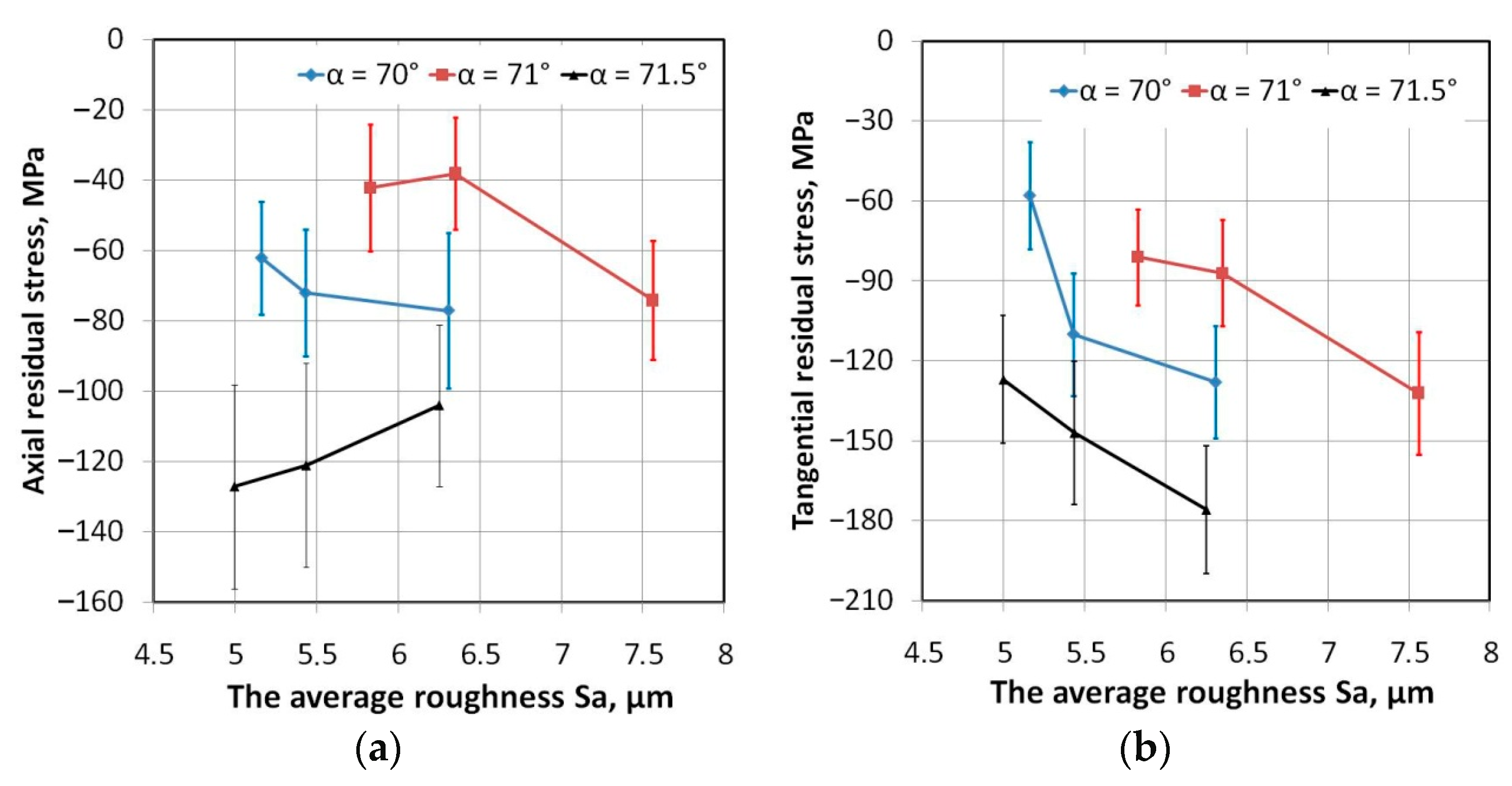
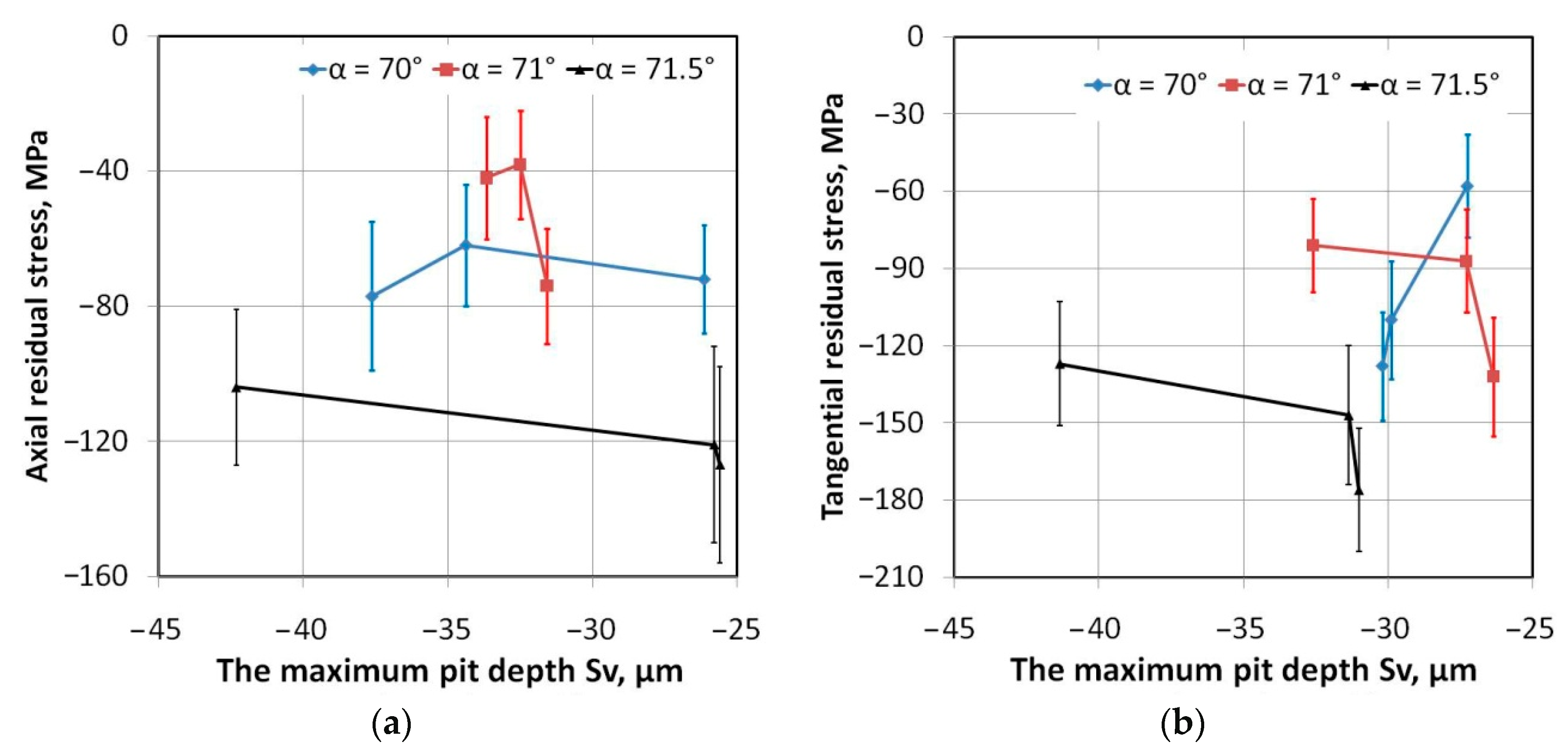
3.3. Residual Stresses

The outer surface of the drawpiece exhibits a compressive magnitude of residual stress (Figure 12). Radu [45], when studying DC04 steel with a thickness of 0.8, found that residual stresses in the material were of a compression type. As for the drawpieces formed at ap = 0.5 mm, α = 70° and ap = 0.5 mm, α = 71°, the residual stress starts to decrease along the surface until it reaches its maximum compressive magnitude value at point 3 (Figure 4). It was found that tangential residual stress was lower than axial stress. In the case of a drawpiece formed at ap = 0.5 mm, α = 71.5° another relationship between the axial and tangential residual stresses than for drawpiece formed at ap = 0.5 mm, α = 70° was revealed. The tangential stress increases between points 1 and 3, while the axial residual stresses decrease.
This variation of stress magnitudes between the measurement points 1 and 3 is an indication of flexural stresses on the conical truncated drawpiece formed from steel. The increase in the slope angle lead to increase of the circumference of the drawpiece at specific cross-sections parallel to the cone base. Base on the constancy-of-volume relationship, when the circumference of the drawpiece at specific cross-section increases, the sheet thickness decreases. In these conditions the stiffness of the drawpiece is smaller and sheet material in smaller extend accumulate the plastic deformation.
The surface roughness of drawpieces was measured at the same locations as the residual stresses (Figure 4). Considering that the stresses were measured in the subsurface layer at a depth of about 5–10 μm, this permitted them to investigate the possible effect of surface topography on the amount of residual stress. The effect of roughness parameters on the value of residual stress is presented in Figure 13, Figure 14 and Figure 15. Only in the case of the Sa parameter, which plays an important role in the characterization of surface roughness in manufacturing processes, can a clear relation between slope angle, average roughness and residual stress be found. Residual stresses measured in a tangential direction decrease with the increasing value of the Sa parameter (Figure 13b). A similar trend is observed for the axial stresses, but only for the drawpieces with slope angles of 70° and 71°. Only in the case of a drawpiece with a slope angle of 71.5° does the increase of the Sa parameter lead to an increase in residual stresses (Figure 13a). Due to the similar trends of the changes of the Sa and Sq parameters (Figure 9 and Figure 10), the above-mentioned conclusions are also valid for the effect of the Sq parameter on the residual stresses.
An increase in step size causes an increase in the axial (Figure 16a) and tangential (Figure 16b) residual stresses, as was also found by Radu et al. [25] and Jimenez et al. [46]. By increasing the tool step-down, the magnitude of the compressive residual stresses on the non-contact surface also increases when forming pyramidal drawpieces [17]. As for step size ap = 0.3 mm, the value of the residual stresses measured in an axial and a tangential direction shows great proportionality (Figure 17a). When step size started to increase, this relationship led to a disturbance. Increase of step size to the maximal value considered, the value ap = 0.7 mm, causes a reversal of the changes of the value of tangential residual stress, and at point 3 the value of the tangential stress is higher than the axial stress. The results allow us to draw the conclusion that the values of the residual stresses measured in the subsurface layer depend on the direction of measurement. The effect of surface roughness on the residual stresses is not entirely clear because the mechanical properties of the sheets change between points 1 and 3 due to the strengthening phenomenon.
The change of residual stresses along the generating line of the cone may be attributed to the strain hardening phenomenon and material field stress. The mechanism of strain hardening is enhanced by the increase in density of the dislocations. On the other hand, dislocations are needed to produce the lattice rotation, and at the same time the remaining dislocation will increase the residual stresses [16]. The intensity and distribution of the residual stresses are controlled by the underlying plastic deformation mechanisms of the forming process, i.e., bending, stretching and through-thickness shear [16]. As Tanaka et al. [24] concluded, the higher the contribution of bending deformation, the more pronounced will be the geometric deviations. The non-compatible strain fields form the other source of residual stresses. The characteristics of the plastic zone are crucial for an understanding of the underlying physics of the deformation process and the generation of residual stress around a crack tip under fatigue loading.

4. Conclusions

The residual stress distribution was investigated along the outer surface of a DC04 steel sheet conical truncated drawpiece processed by SPIF. A XRD analysis has been carried out in an axial and tangential direction. The following conclusions are drawn from the research:
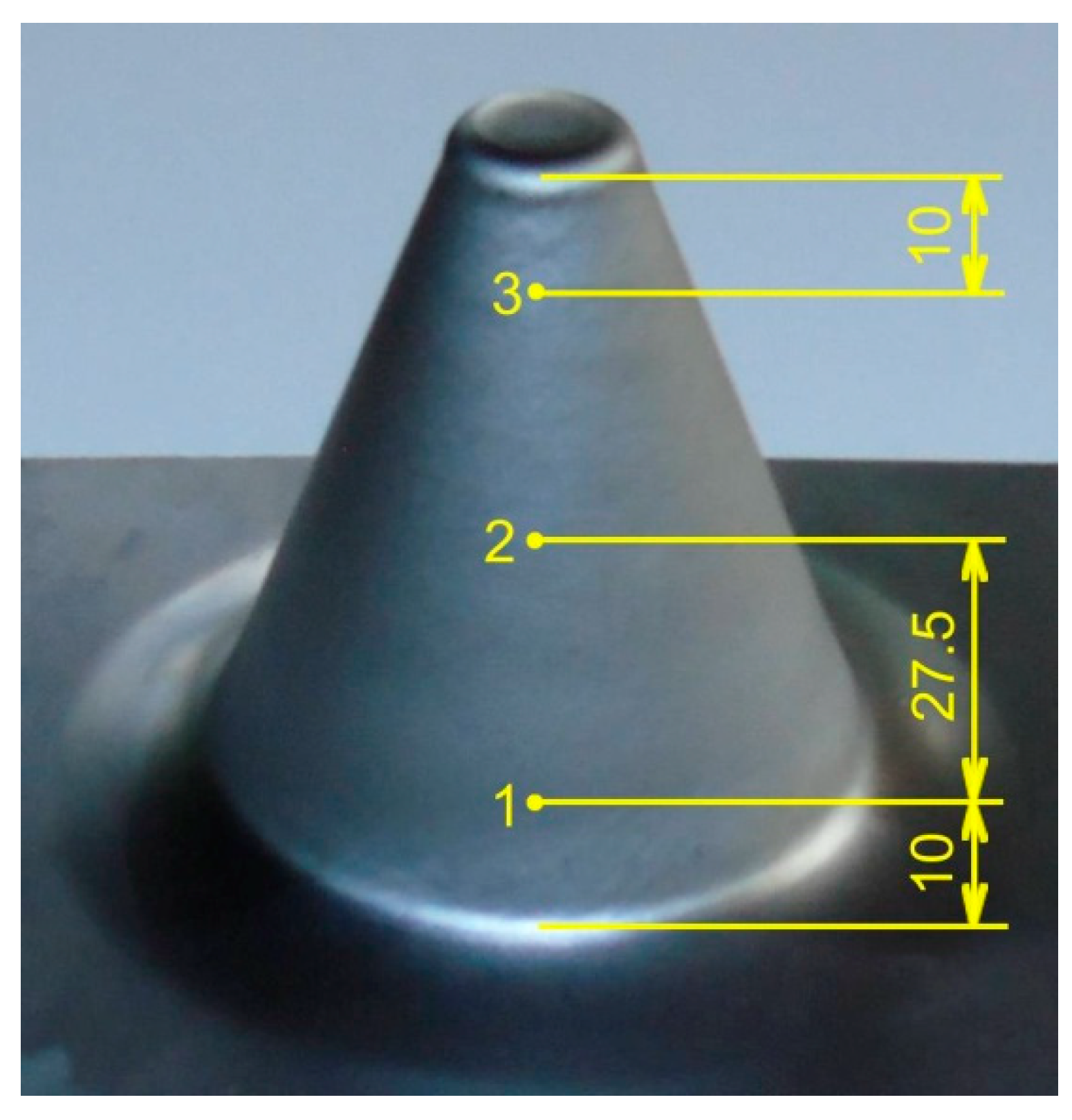
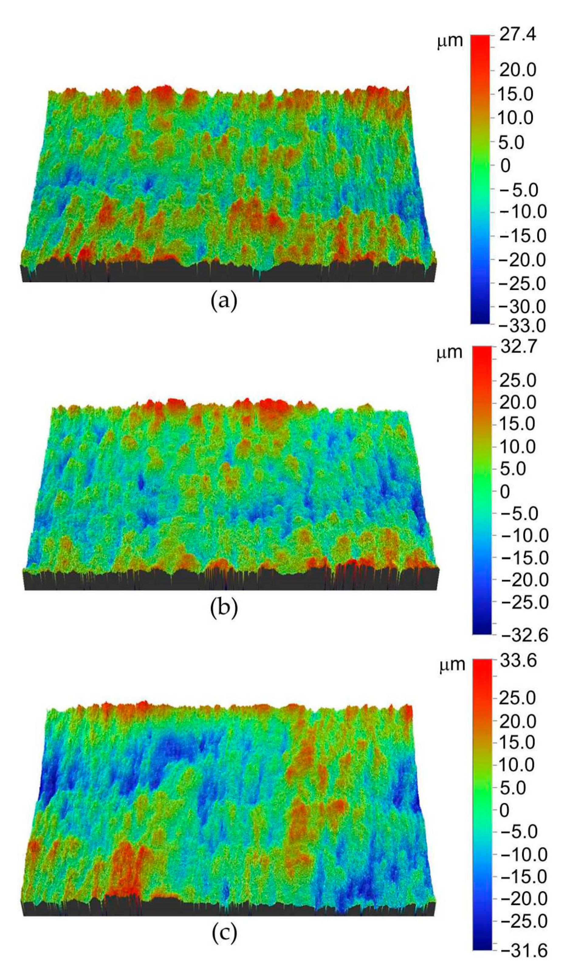
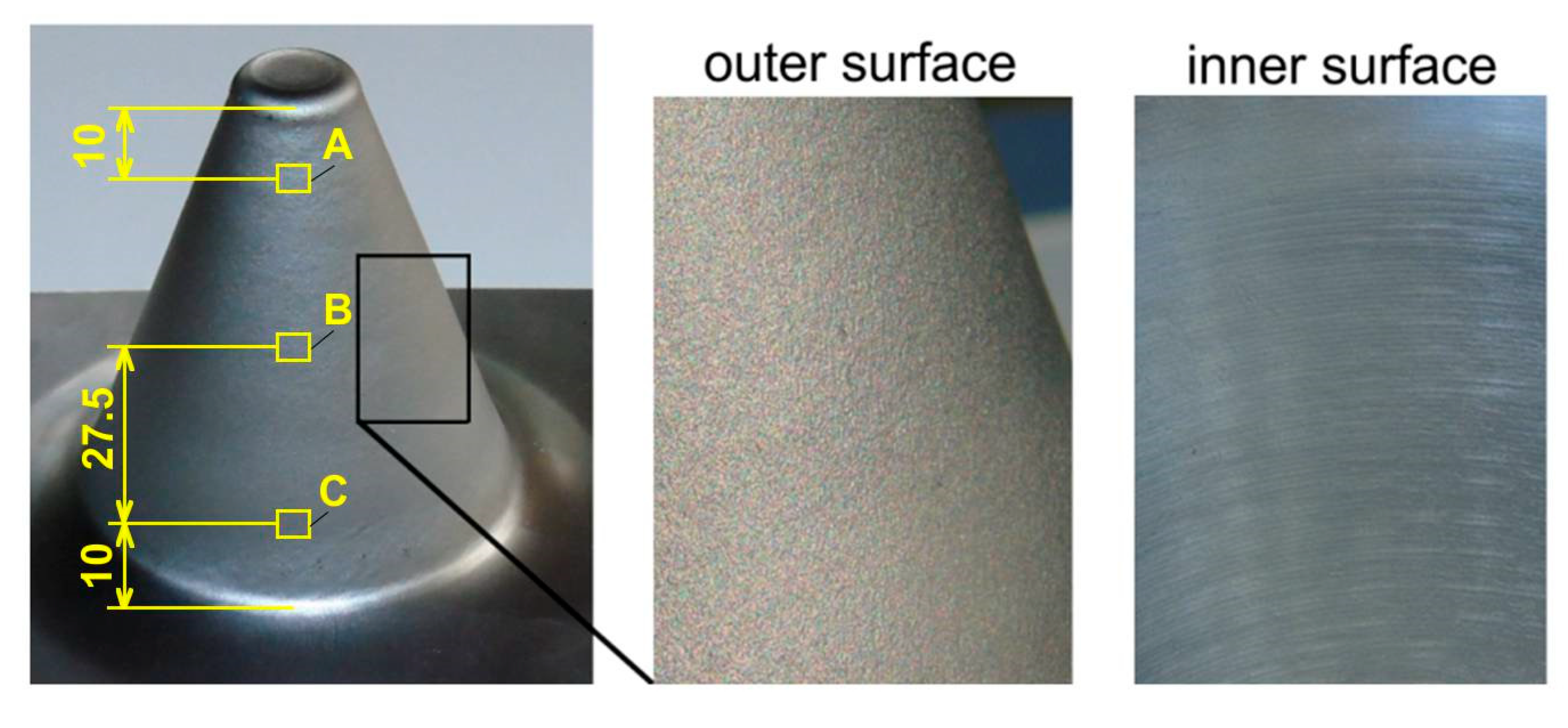
  • The inner surface of the drawpiece revealed small linear grooves as a result of the interaction of the tool tip with the workpiece. The surface finish of the outer surface of a drawpiece is the result of small-scale roughness induced by large surface strains which leads to an orange peel phenomenon.
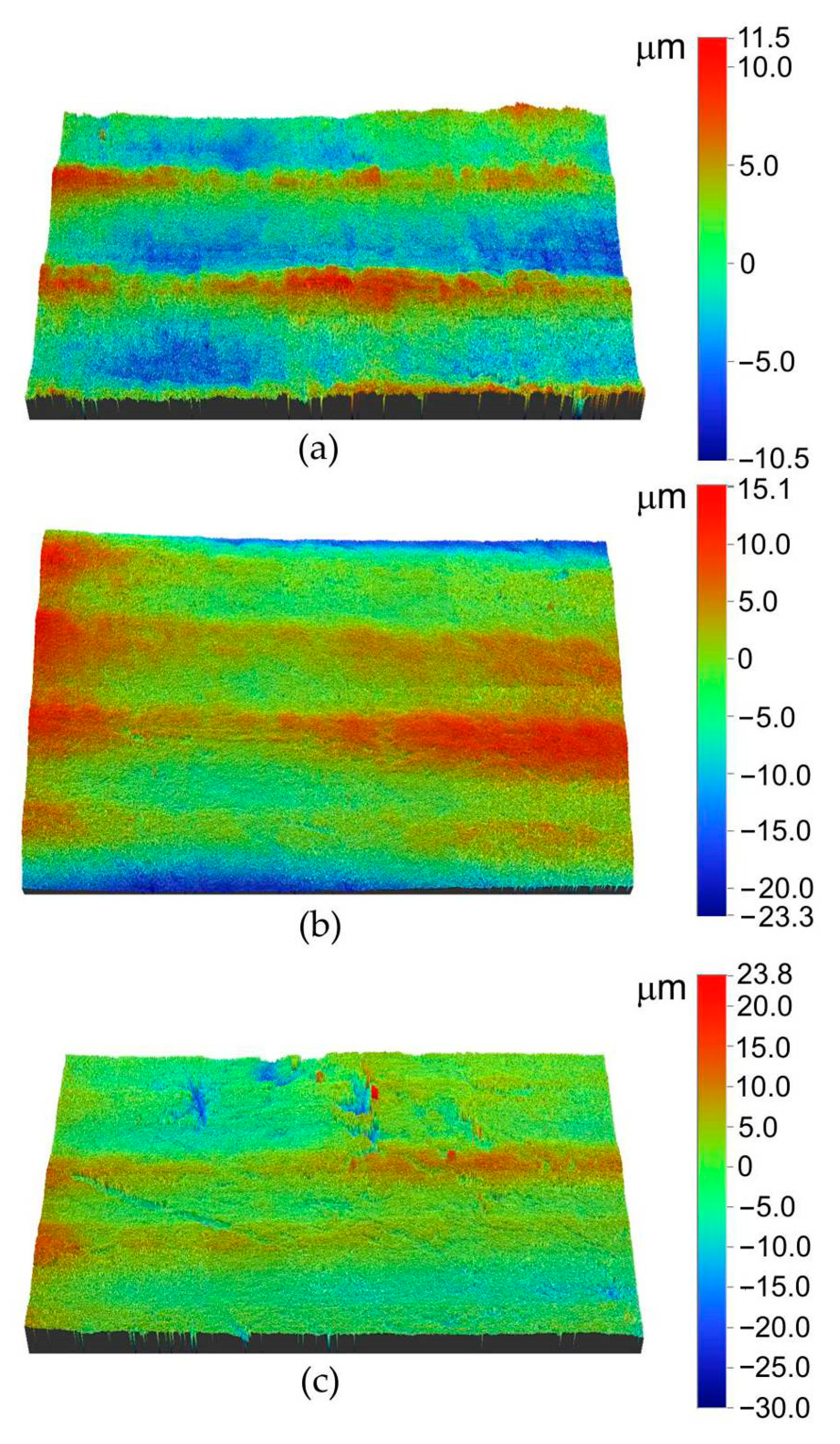
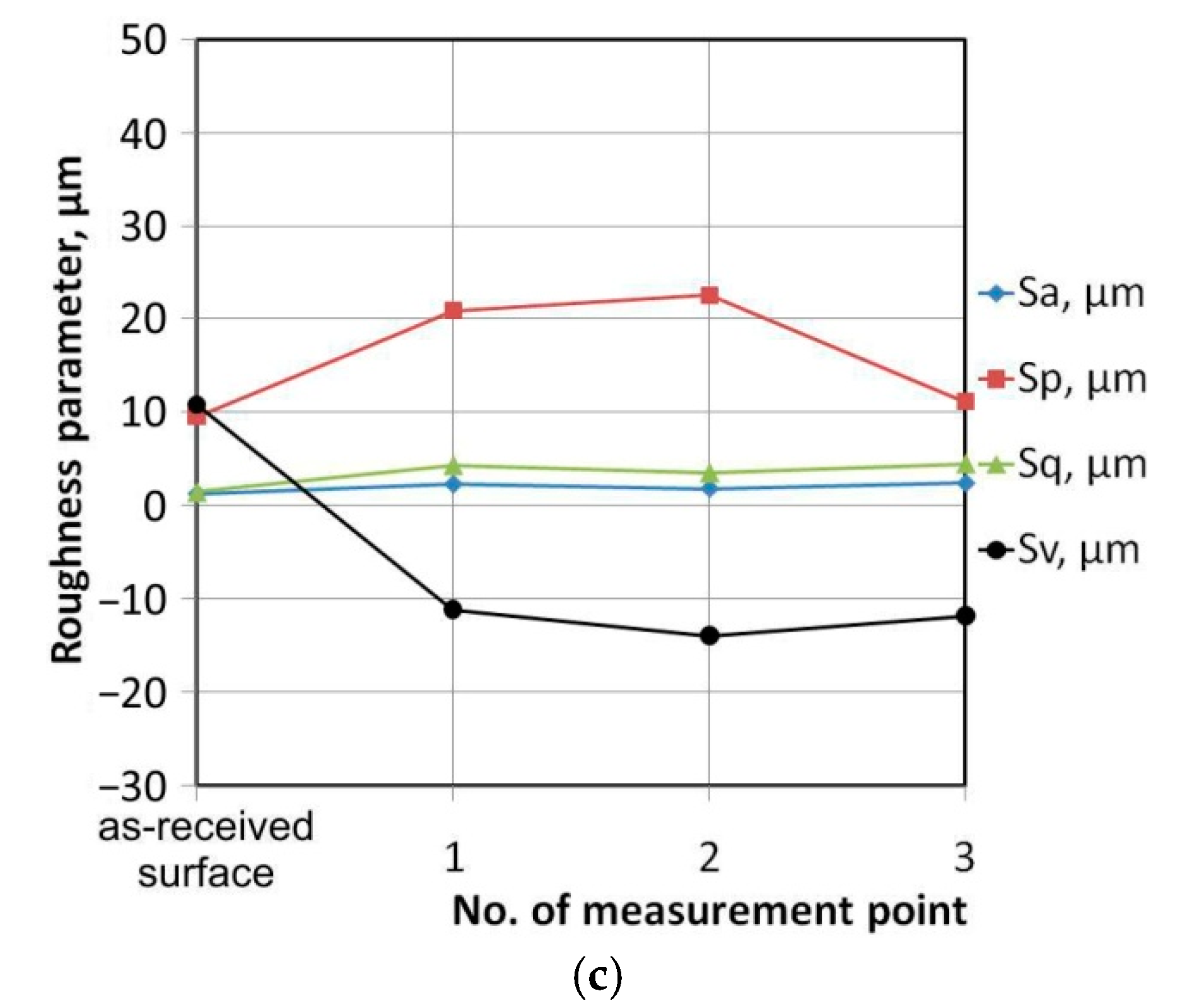
  • On both the inner and outer surfaces of the drawpiece, an increase of the Sa, Sp, and Sq parameters was found along the generating line of the cone when compared to the as-received surface. Moreover, a clear reduction in the Sv parameter was revealed.
  • The inner and outer surfaces, characterized by their average roughness values, was not significantly affected by step size. In the case of the outer surface, only a small increase in the Sa parameter is observed along the generating line of the cone.
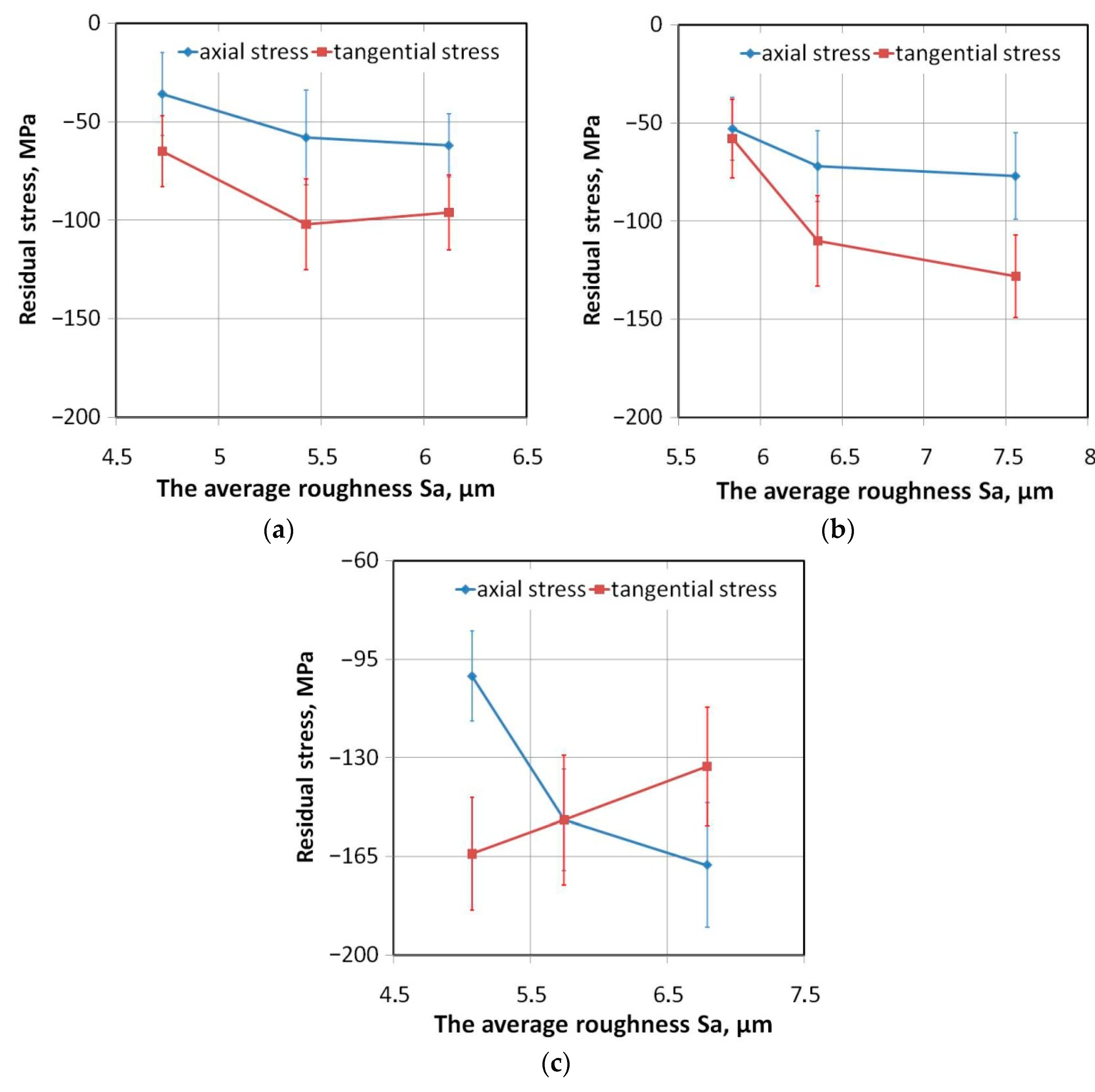
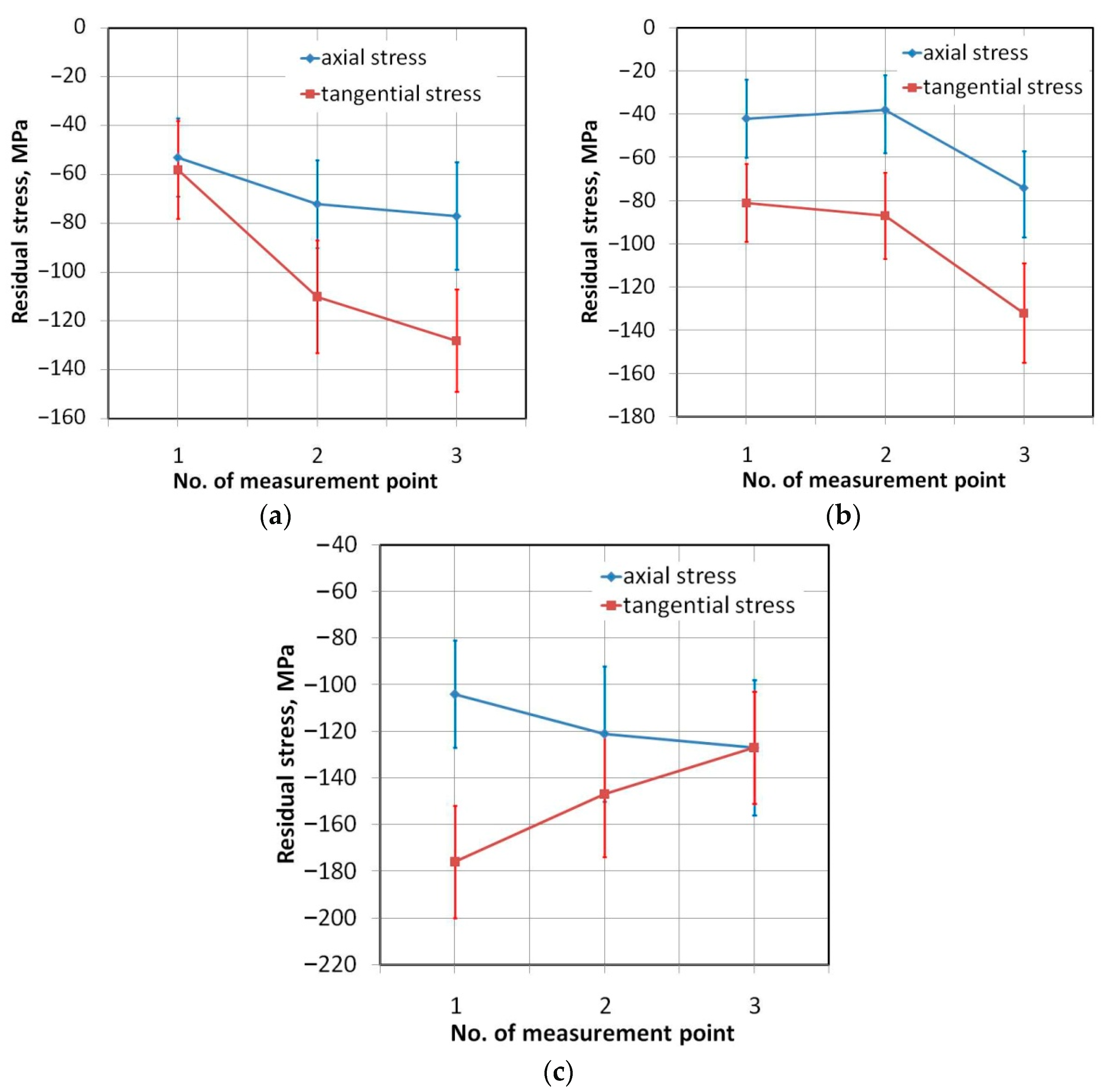
  • The outer surface of the drawpiece exhibits a compressive magnitude of residual stress in both the axial and tangential direction. The value of tangential residual stresses was lower than axial stresses.
  • Residual stresses measured in a tangential direction decrease with an increase in the value of the Sa parameter.
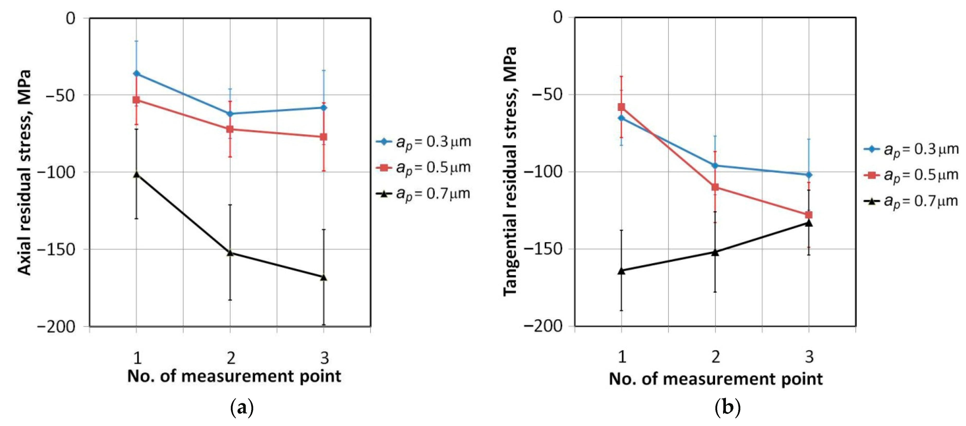
  • Step size had a very large impact on the value of residual stresses. An increase in step size causes an increase in the absolute values of axial and tangential residual stresses.
  • Residual stresses measured in a tangential direction decrease with the increasing value of the Sa and Sq parameters. A similar trend is observed for the axial stresses, but only for the drawpieces with slope angles of 70° and 71°. No clear relationship was found between the rest of roughness parameters and residual stress values.
  • The geometric deviations found in the incrementally formed drawpieces are a result of local springback behind the actual forming process as well as springback upon unclamping and upon trimming. To better understand the role of residual stress on the geometric accuracy of the SPIFed part, the effect of the process parameters on the residual stresses after different stages of drawpiece fabrication will be analyzed in future research.

Author Contributions

Conceptualization, B.K., A.K. and T.T., investigation, B.K., A.K., T.T., W.B., K.D. and M.N.; formal analysis, J.S.; validation, B.K., A.K., T.T., K.D. and M.N.; project administration, J.S.; funding acquisition, J.S.; writing–original draft, T.T.; writing–review and editing, T.T. All authors have read and agreed to the published version of the manuscript.

Funding

This research was funded by the Grant Agency of the Ministry of Education, Science, Research and Sport of the Slovak Republic, grant number VEGA 1/0259/19.

Conflicts of Interest

The authors declare no conflict of interest.

References

  1. Duflou, J.R.; Habraken, A.M.; Cao, J.; Malhotra, R.; Bambach, M.; Adams, D.; Vanhove, H. Single point incremental forming: State-of-the-art and prospects. Int. J. Mater. Form. 2018, 11, 743–773. [Google Scholar] [CrossRef]
  2. Martins, P.A.F.; Bay, N.; Skjoedt, M.; Silva, M.B. Theory of single point incremental forming. Cirp Ann. Manuf. Technol. 2008, 57, 247–252. [Google Scholar] [CrossRef]
  3. Trzepiecinski, T.; Lemu, H.G. Effect of computational parameters on springback prediction by numerical simulation. Metals 2019, 7, 380. [Google Scholar] [CrossRef] [Green Version]
  4. Maaß, F.; Gies, S.; Dobecki, M.; Brömmelhoff, K.; Tekkaya, A.E.; Reimers, W. Analysis of residual stress state in sheet metal parts processed by single point incremental forming. AIP Conf. Proc. 2018, 1960, 160017. [Google Scholar]
  5. Micari, F.; Ambrogio, G.; Filice, L. Shape and dimensional accuracy in single point incremental forming: State of the art and future trends. J. Mater. Process. Technol. 2007, 191, 390–395. [Google Scholar] [CrossRef]
  6. Ambrogio, G.; Cozza, V.; Filice, L.; Micari, F. An analytical model for improving precision in single point incremental forming. J. Mater. Process. Technol. 2007, 191, 92–95. [Google Scholar] [CrossRef]
  7. Blaga, A.; Oleksik, V. A study on the influence of the forming strategy on the main strains, thickness reduction, and forces in a single point incremental forming process. Adv. Mater. Sci. Eng. 2013, 2013, 382635. [Google Scholar] [CrossRef] [Green Version]
  8. Behera, A.K.; de Sousa, R.A.; Ingarao, G.; Oleksik, V. Single point incremental forming: An assessment of the progress and technology trends from 2005 to 2015. J. Manuf. Process. 2017, 27, 37–62. [Google Scholar] [CrossRef] [Green Version]
  9. Lasunon, O.U. Surface roughness in incremental sheet metal forming of AA5052. Adv. Mater. Res. 2013, 753-755, 203–206. [Google Scholar] [CrossRef]
  10. Hagan, E.; Jeswiet, J. Analysis of surface roughness for parts formed by computer numerical controlled incremental forming. Proc. Inst. Mech. Eng. Part B J. Eng. Manuf. 2004, 218, 1307–1312. [Google Scholar] [CrossRef]
  11. Aldo, A.; Ceretti, E.; Giardini, C. Optimization of tool path in two points incremental forming. J. Mater. Process. Technol. 2006, 177, 409–412. [Google Scholar]
  12. Powers, B.M.; Ham, M.; Wilkinson, M.G. Small data set analysis in surface metrology: An investigation using a single point incremental forming case study. Scanning 2010, 32, 199–211. [Google Scholar] [CrossRef]
  13. Al-Ghamdi, K.A.; Hussain, G. On the free-surface roughness in incremental forming of a sheet metal: A study from the perspective of ISF strain, surface morphology, post-forming properties, and process conditions. Metals 2019, 9, 553. [Google Scholar] [CrossRef] [Green Version]
  14. Durante, M.; Formisano, A.; Langella, A.; Minutolo, F.M.C. The influence of tool rotation on an incremental forming process. J. Mater. Process. Technol. 2009, 209, 4621–4626. [Google Scholar] [CrossRef]
  15. Gatea, S.; Ou, H.; McCartney, G. Review on the influence of process parameters in icremental sheet forming. Int. J. Adv. Manuf. Technol. 2016, 87, 479–499. [Google Scholar] [CrossRef] [Green Version]
  16. Maqbool, F.; Bambach, M. Dominant deformation mechanisms in single point incremental forming (SPIF) and their effect on geometrical accuracy. Int. J. Mech. Sci. 2018, 136, 279–292. [Google Scholar] [CrossRef]
  17. Maqbool, F.; Bambach, M. Experimental and numerical investigation of the influence of process parameters in incremental sheet metal forming on residual stresses. J. Manuf. Mater. Process. 2019, 3, 31. [Google Scholar] [CrossRef] [Green Version]
  18. Huber, N.; Heerens, J. On the effect of a general residual stress state on indentation and hardness testing. Acta Mater. 2008, 56, 6205–6213. [Google Scholar] [CrossRef] [Green Version]
  19. Bambach, M.; Araghi, B.T.; Hirt, G. Strategies to improve the geometric accuracy in asymmetric single point incremental forming. Prod. Eng. 2009, 3, 145–156. [Google Scholar] [CrossRef]
  20. Radu, C.; Herghelegiu, E.; Tampu, N.C.; Cristea, I. The residual stress state generated by single point incremental forming of aluminum metal sheets. Appl. Mech. Mater. 2013, 371, 148–152. [Google Scholar] [CrossRef]
  21. Shi, X.; Hussain, G.; Butt, S.I.; Song, F.; Huang, D.; Liu, Y. The state of residual stresses in the Cu/Steel bonded laminates after ISF deformation: An experimental analysis. J. Manuf. Process. 2017, 30, 14–26. [Google Scholar] [CrossRef]
  22. Kotobi, M.; Honarpisheh, M. Uncertainty analysis of residual stresses measured by slitting method in equal-channel angular rolled Al-1060 strips. J. Strain Anal. Eng. Des. 2017, 52, 83–92. [Google Scholar] [CrossRef]
  23. Alinaghian, I.; Amini, S.; Honarpisheh, M. Residual stress, tensile strength, and macrostructure investigations on ultrasonic assisted friction stir welding of AA6061-T6. J. Strain Anal. Eng. Des. 2018, 53, 494–503. [Google Scholar] [CrossRef]
  24. Tanaka, S.; Nakamura, T.; Hayakawa, K.; Nakamura, H.; Motomura, K. Residual stress in sheet metal parts made by incremental forming process. AIP Conf. Proc. 2017, 908, 775. [Google Scholar]
  25. Radu, C.; Tampu, C.; Cristea, I.; Chirita, B. The effect of residual stresses on the accuracy of parts processed by SPIF. J. Mater. Manuf. Process. 2013, 28, 572–576. [Google Scholar] [CrossRef]
  26. Maaß, F.; Hahn, M.; Dobecki, M.; Thannhauser, E.; Tekkaya, A.E.; Reimers, W. Influence of tool path strategies on the residual stress development in single point incremental forming. Procedia Manuf. 2019, 29, 53–58. [Google Scholar] [CrossRef]
  27. Abdulrazaq, M.M.; Gazi, S.K.; Ibraheem, M.Q. Investigation the influence of SPIF parameters on residual stresses for angular surfaces based on ISO-planar tool path. Al-Khwarizmi Eng. J. 2019, 15, 50–59. [Google Scholar] [CrossRef] [Green Version]
  28. Al-Ghamdi, K.A.; Hussain, G. Stress gradient due to incremental forming of bonded metallic laminates. J. Mater. Manuf. Process. 2017, 32, 1384–1390. [Google Scholar] [CrossRef]
  29. Alinaghian, M.; Alinaghian, I.; Honarpisheh, M. Residual stress measurement of single point incremental formed Al/Cu bimetal using incremental hole-drilling method. Int. J. Lightweight Mater. Manuf. 2019, 2, 131–139. [Google Scholar] [CrossRef]
  30. Hajavifard, R.; Maqbool, F.; Schmiedt-Kalenborn, A.; Buhl, J.; Bambach, M.; Walther, F. Integrated forming and surface engineering of disc springs by inducing residual stresses by incremental sheet forming. Materials 2019, 12, 1646. [Google Scholar] [CrossRef] [Green Version]
  31. López, C.; Elías-Zúñiga, A.; Jiménez, I.; Martínez-Romero, O.R.; Siller, H.; Diabb, J.M. Experimental determination of residual stresses generated by single point incremental forming of AlSi10Mg sheets produced using SLM additive manufacturing process. Materials 2018, 11, 2542. [Google Scholar] [CrossRef] [Green Version]
  32. Ham, M.; Powers, B.M.; Loiselle, J. Surface topography from single point incremental forming using an acetal tool. Key Eng. Mater. 2013, 549, 84–91. [Google Scholar] [CrossRef]
  33. Ham, M.; Powers, B.M.; Loiselle, J. Multiscale analysis of surface topography from single point incremental forming using an acetal tool. J. Phys. Conf. Ser. 2014, 483, 012008. [Google Scholar] [CrossRef]
  34. Li, X.; Liu, Z.; Liang, X. Tool wear, surface topography, and multi-objective optimization of cutting parameters during machining AISI 304 austenitic stainless steel flange. Metals 2019, 9, 972. [Google Scholar] [CrossRef] [Green Version]
  35. Oraon, M. Surface roughness evaluation of AA 3003 alloy in single point incremental forming technique. Int. J. Sci. Eng. Res. 2018, 9, 28–34. [Google Scholar]
  36. Behera, A.K.; Ou, H. Effect of stress relieving heat treatment on surface topography and dimensional accuracy of incrementally formed grade 1 titanium sheet parts. Int. J. Adv. Manuf. Technol. 2016, 87, 3233–3248. [Google Scholar] [CrossRef] [Green Version]
  37. Ambrogio, G.; Filice, L.; Gagliardi, F.; Micari, F. Sheet thinning prediction in single point incremental forming. Adv. Mater. Res. 2005, 6–8, 479–486. [Google Scholar] [CrossRef]
  38. Shamsari, M.; Mirnia, M.J.; Elyas, M.; Baseri, H. Formability imrpovement in singe point incremental forming of truncated cone using a two-stage hybrid deformation strategy. Int. J. Adv. Manuf. Technol. 2018, 94, 2357–2368. [Google Scholar] [CrossRef]
  39. Liu, Z.; Li, Y.; Meehan, P.A. Tool path strategies and deformation analysis in multi-pass incremental sheet forming process. Int. J. Adv. Manuf. Technol. 2014, 75, 395–409. [Google Scholar] [CrossRef]
  40. Said, L.B.; Mars, J.; Wali, M.; Dammak, F. Effects of the tool path strategies on incremental sheet metal forming process. Mech. Ind. 2016, 17, 411. [Google Scholar] [CrossRef]
  41. Gatea, S.; Xy, D.; Ou, H.; McCartney, G. Evaluation of formability and fracture of pure titanium in incremental sheet forming. Int. J. Adv. Manuf. Technol. 2018, 95, 625–641. [Google Scholar] [CrossRef] [Green Version]
  42. Kim, Y.H.; Park, J.J. Effect of process parameters on formability in incremental forming of sheet metal. J. Mater. Process. Technol. 2002, 130–131, 42–46. [Google Scholar] [CrossRef]
  43. Liu, Z.; Liu, S.; Li, Y.; Meehan, P.A. Modeling and optimization of surface roughness in incremental sheet forming using a multi-objective function. Mater. Manuf. Process. 2014, 29, 808–818. [Google Scholar] [CrossRef]
  44. Oleksik, V.; Pascu, A.; Deac, C.; Fleacă, R.; Bologa, O.; Racz, G. Experimental study on the surface quality of the medical implants obtained by single point incremental forming. Int. J. Mater. Form. 2010, 3, 935–938. [Google Scholar] [CrossRef]
  45. Radu, C. Analysis of the correlation accuracy-distribution of residual stresses in the case of parts processed by SPIF. Mathematical models and methods in modern science. In Proceedings of the 14th WSEAS International Conference on Mathematical Methods, Computational Techniques and Intelligent Systems, Porto, Portugal, 1–3 July 2012; pp. 195–199. [Google Scholar]
  46. Jiménez, I.; López, C.; Martinez-Romero, O.; Mares, P.; Siller, H.R.; Diabb, J.; Sandoval-Robles, J.A.; Elías-Zúñiga, A. Investigation of residual stress distribution in single point incremental forming of aluminum parts by X-ray diffraction technique. Int. J. Adv. Manuf. Technol. 2017, 91, 2571–2580. [Google Scholar] [CrossRef]
Figure 1. Geometry (a) and view (b) of the forming tool: 1—ER collet, 2—spindle, 3—workpiece, 4—holding ring, 5—body.
Metals 10 00237 g001
Figure 2. Tooling model with the tool path generated.
Metals 10 00237 g002
Figure 3. X-ray diffraction (XRD) methodology.
Metals 10 00237 g003
Figure 4. Location of the stress measurement points.
Metals 10 00237 g004
Figure 5. Morphology of fracture of drawpieces formed with the following parameters: (a) α = 71°, ap = 0.3 mm; (b) α = 71.5°, ap = 0.3 mm; (c) α = 72°, ap = 0.3 mm; (d) α = 72°, ap = 0.5 mm; (e) α = 72°, ap = 0.7 mm.
Metals 10 00237 g005
Figure 6. View of the outer and inner surface of the drawpiece.
Metals 10 00237 g006
Figure 7. Surface topography of the outer surface of the drawpiece with a slope angle α = 71° formed at step size ap = 0.5 mm; surface topographies (a), (b) and (c) are measured in locations of A, B and C indicated in Figure 6, respectively.
Metals 10 00237 g007
Figure 8. Surface topography of the inner surface of the drawpiece with a slope angle α = 71° formed at step size ap = 0.5 mm; surface topographies (ac) are measured in locations of A, B and C indicated in Figure 6, respectively.
Metals 10 00237 g008
Figure 9. Variation of surface roughness parameters on the outer surface of a drawpiece with a slope angle α = 70° formed at step size (a) ap = 0.3 mm, (b) ap = 0.5 mm and (c) ap = 0.7 mm.
Metals 10 00237 g009
Figure 10. Variation of surface roughness parameters on the inner surface of a drawpiece with a slope angle α = 70° formed at step size (a) ap = 0.3 mm, (b) ap = 0.5 mm and (c) ap = 0.7 mm.
Metals 10 00237 g010aMetals 10 00237 g010b
Figure 11. Variation of surface roughness parameters (a) Sa, (b) Sp, (c) Sq and (d) Sv on the outer surface of a drawpiece formed at step size ap = 0.5 mm.
Metals 10 00237 g011
Figure 12. Variation of residual stress on the outer surface of a drawpiece with a slope angle (a) α = 70°, (b) α = 71° and (c) α = 71.5°, formed at step size ap = 0.5 mm.
Metals 10 00237 g012
Figure 13. Effect of the average roughness Sa on the variation of (a) axial and (b) tangential residual stresses in the outer surface of a drawpiece formed at a step size ap = 0.5 mm.
Metals 10 00237 g013
Figure 14. Effect of the highest peak of the surface Sp on the variation of (a) axial and (b) tangential residual stresses in the outer surface of a drawpiece formed at step size ap = 0.5 mm.
Metals 10 00237 g014
Figure 15. Effect of the maximum pit depth Sv on variation of (a) axial and (b) tangential residual stresses in the outer surface of a drawpiece formed at a step size ap = 0.5 mm.
Metals 10 00237 g015
Figure 16. Effect of the step size ap on the variation of (a) axial and (b) tangential residual stresses on the outer surface of a drawpiece with a slope angle α = 70°.
Metals 10 00237 g016
Figure 17. Effect of the average roughness Sa on the variation of residual stresses in the outer surface of a drawpiece with a slope angle α = 70° formed at a step size (a) ap = 0.3 mm, (b) ap = 0.5 mm and (c) ap = 0.7 mm.
Metals 10 00237 g017
Table 1. The chemical composition (in weight%) of DC04 steel sheet.
CMnCuNiCrAlTiMoVSSiFe
0.0160.1880.060.0420.0210.0350.0220.0030.0200.0040.003Rest
Table 2. Basic mechanical properties of DC04 steel sheet.
Specimen
Orientation
Yield Stress Rp02, MPaUltimate Tensile Stress Rm, MPaElongation A50, %Strengthening Coefficient K, MPaStrain Hardening Exponent n
184.5303.923.0490.40.205
45°193.7314.922.1489.90.164
90°176.1296.022.8465.70.169
Table 3. Results of experimental tests (√ means that drawpiece has been successfully formed)
Slope Angle α (°)Step Size ap (mm)
0.30.50.7
70
71Fractured at h = 15.6 mm
71.5Fractured at h = 16.5 mm
72Fractured at h = 16.5 mmFractured at h = 18.9 mmFractured at h = 20.4 mm

