Remote Fibre Laser Welding of Advanced High Strength Martensitic Steel
by
 ,
,
Urban Prijanovič
1, 
Marica Prijanovič Tonkovič
2,
Uroš Trdan
3,*,
Matej Pleterski
4,
Matija Jezeršek
3 and
Damjan Klobčar
3,* 1
TPV Group Corporation, Kandijska 60, 8000 Novo mesto, Slovenia
2
High Mechanical Engineering School, Šegova 112, 8000 Novo mesto, Slovenia
3
Faculty of Mechanical Engineering, University of Ljubljana, Aškerčeva cesta 6, 1000 Ljubljana, Slovenia
4
NUMIP Engineering, Construction, Maintenance and Production Ltd., Cesta krških žrtev 135b, 8270 Krško, Slovenia
*
Authors to whom correspondence should be addressed.
Metals 2020, 10(4), 533; https://doi.org/10.3390/met10040533
Submission received: 21 March 2020
/
Revised: 15 April 2020
/
Accepted: 18 April 2020
/
Published: 20 April 2020
(This article belongs to the Special Issue Microstructure and Properties of Metallic Heat-Affected Zones)
Abstract
:The study presents the results of remote robotic laser welding of advanced high strength Docol® 1200 M martensitic steel. One mm thick samples were welded in a lap joint configuration using a special clamping system. Welding was done using a continuous-wave (CW) fibre laser with a constant welding power of 300 W and constant focus diameter Ø 1.8 mm. Welding was done using 12 different welding speeds in the range from 0.15 to 1 m/min, whereas the inclination angle was kept constant at 0°. The influence of various welding speeds and linear heat inputs during welding on microstructural changes were examined by the occurrence of acicular and allotriomorphic ferrite or martensite. Results revealed big influence of the clamping system on the accumulation of the laser beam energy, heat sink and consequently weld size and geometry, as well as its microstructure and joint strength. Tensile-shear strength, microstructure and hardness results confirmed laser power of 300 W and 0.6 m/min welding speed as the optimal parameters, at which a martensitic structure was obtained in the weld. The width of the heat affected zone (HAZ) in this case is 1100 μm.
1. Introduction
The transportation industry is under a constant pressure toward cleaner, more efficient and sustainable production with reduced fuel consumption to decrease the negative impact on the environment. Moreover, requirements are dictated by ever-shorter and rigorous timeframes with controlled, high-productivity and sustainably oriented manufacturing technologies. One of the ways to achieve mass reduction, financial savings and extend the life of vehicle machine parts and components is the implementation of new/innovative materials combined with laser technologies. The selection of proper materials for the given application, by using multi-material components, with good strength to weight ratio and optimisation of joining technologies plays a crucial role.
Nowadays, there are many types of high strength steels known and used in the practical application [1]. In the automotive industry dual-phase (DP) and transformation-induced plasticity (TRIP) [2,3] steels are used for structural and safety parts such as B-pillar reinforcements, cross members, longitudinal beams, bumper reinforcements, seat structures and seat mechanisms [3,4,5,6,7,8,9]. DP steels are also used for painted surfaces used for roof, door, body side, hood, fender, while TRIP steels are also used for armour applications [3,4,5,6,7,8,9]. Docol® steels (SSAB AB, Stockholm, Sweden) are martensitic advanced high-strength steels (AHSS) produced in thicknesses from 0.50 to 4.00 mm which have a maximal carbon content between 0.15 and 0.25%. It has shear strength higher than 980 MPa and ultimate tensile strength reaching up to 1400 MPa (e.g. can be found in construction elements for passenger safety cell as they allow minimal deformations of body in white (BIW), hence enabling maximum passenger safety [10,11]. The advantage of AHSS steels compared to other materials such as composites, aluminium and magnesium alloys is that they have good formability, recyclability and weldability in addition to their lower price, due to the small amount of alloying elements in steel [2,12,13,14].
Moreover, the conventional martensitic steel grades are progressively replaced in many applications by press-hardening steels and quench-and-partitioning steels. Several researchers investigated the post-weld heat treatment of AHSS after laser welding of butt welds [15]. A very promising is a quenching and partitioning heat treatment (Q&PHT) which consists of: (i) fully or partially austenitization (ii) quenching the steel to a temperature between Ms and Mf to make a volume fraction of martensite and followed by (iii) heating to a temperature above or below the Ms temperature i.e., partitioning temperature (PT), where the carbon diffuse from martensite to austenite [15].
Nonetheless, it should be noted that chemical composition as well as mechanical and heat pre-treatment have an enormous effect on the weldability of high strength steels. Vanovsek et al. [11] studied the effect of aluminium content on microstructure and formation of inclusions in the welds of U/AHSS steel. Their results revealed that the strength and ductility of U/AHSS depend on the size and number of inclusions that are formed during the solidification process. The presence of hydrogen is unwanted due to its diffusion tendency to the crystal boundaries during cooling of the weld. Hence, introduction of hydrogen during welding of U/AHSS steels, due to the chemically bonded water/moisture in the electrode, filler material and shielding gas, etc., must be strictly avoided to prevent embrittlement [2,16]. The presence of hydrogen in concentration of a few parts per million is often enough to cause brittle failure [2].
U/AHSS steels can be welded using various welding technologies, e.g. resistance spot welding, arc welding [13,17], laser welding, electron beam welding and other joining technologies. The welding technology is usually chosen based on the wall thickness of the element in a joint, joint type, quality, quantity, etc. Thicker work pieces are usually welded using Gas Metal Arc Welding (GMAW) or with shielded metal arc welding (SMAW), although some research is done using high power laser welding [13,18]. Thin steel plates are mostly welded using resistance spot or projection welding [19] and laser welding [20,21], or lately also using Cold Metal Transfer CMT GMAW process [22]. Kim et al. [22] investigated the effect of Al-Si coating on laser weldability of U/AHSS steels with tensile strength of around 1500 MPa. It was confirmed that with Al-Si coated steel, an intermetallic phase developed during the welding that had a detrimental effect which weakened the strength of a joint.
Furthermore, recently extensive research efforts have been devoted to exploit resistance welding and automated laser welding technologies for joining AHSS. For example, Górka et al. [13] used robotic resistance spot welding of 1.8 mm thick Docol® 1200M steel in a lap joint to determine the structure and properties of joints. In another study, Górka and Ozgowicz [23] laser welded AHSS Docol® 1200M of 1.8 mm thickness in the overlapped joint configuration. In the weld area they obtained martensitic microstructure. They found that the martensite needles enlarged with increasing linear heat input and that HAZ had a microstructure of tempered martensite.
Moreover, Guo and Li [18] laser welded high strength steels (S960 and S700) of 8 mm and 13 mm thickness in butt weld configuration. Laser welding was done in single pass and multipass with ultra-narrow gap using a 16 kW fiber laser. They found that cracking in the welded joints could be avoided. The fast cooling rate during laser welding causes the generation of hard martensite in the fusion zone (FZ) and heat affected zone (HAZ). Laser welding with higher heat input causes the formation of bainite in the FZ, while hard martensite and bainite were formed in the HAZ. The tensile strength and elongation of laser welded specimens remained the same than that of the base materials. Górka [24] laser welded 10 mm thick butt joints made of steel 700 MC subjected to the TMCP (thermo-mechanically controlled processed) process. Laser welding was done using linear energies of 4 kJ/mm and 5 kJ/mm. The obtained tensile strength of the joints was only 5% lower than of the base metal. In the welded joint precipitation hardening with finely dispersed (Ti, Nb) (C, N) type precipitates (several nanometres in size) were observed, which resulted in the reduction of plastic properties. An increase in hardening element levels, i.e., Ti and Nb, reduced the weld toughness to a value of 25 J/cm2. They concluded that phase transformation of austenite due to thermal welding cycles and the value of carbon equivalent (CE) are not the only factors to be considered for assessing weldability.
Lasers are movable heat sources that are also used for material processing steps like cutting, heat treatment, drilling, welding, additive manufacturing (powder bed and direct energy deposition) and forming. Modelling temperature fields produced by moving laser heat source are very important for understanding of phase transformations that are occurring at laser welding of AHSS [21,25].
Nĕmeček and Mužík [26] studied the differences between laser and GMA welding of AHSS TRIP 900 and high strength martensitic with 0.11 wt.% C and 1.4 wt.% Mn. They studied the effect of main welding parameters on the formation of weld and HAZ microstructure and hardness properties. The welds have a ferritic microstructure in different morphological forms, i.e., acicular, allotriomorphic, widmanstätten or proeutectoidic ferrite. Due to the relatively large austenitic grains and high density of intergranular nucleation sites acicular ferrite predominated inside austenitic grains. The formation of acicular ferrite in the weld of high strength steels depends on many factors; the linear heat input in during the welding, presence of oxygen, type and quantity of alloying elements, the size of austenitic grain as well as the type, size and number of non-metal inclusions such as: TiO2, Al2O3, SiO2, MnO-SiO2, Al2O3-MnO-SiO2, MnS, TiN, MnOAl2O3, MnOTiO2, MnS [27].
Radwański et al. [14] have done the microstructure characterisation and modelling of the mechanical properties of DP HCT600X steel. In the multiphase microstructure they characterized ferrite as a matrix phase and a fine dispersion of martensitic/bainitic islands. They determined the area fraction, mean equivalent diameter, and mean free distance of observed phases.
Although, the resistance spot welding (RSW) process is used extensively in the automotive industry, the use of laser welding is constantly increasing, since a substantial weight reduction of components and car body can be achieved as a consequence of different joint design [28,29]. The use of lasers predominantly depends on the power used [30].
There are several types of lasers used in industry like CO2 lasers, laser diodes (LDs), lamp pumped neodymium-doped yttrium aluminium garnet (Nd: YAG) lasers, LD-pumped solid state lasers, fibre lasers, etc. [28,31]. Depending on the laser system and materials the welding speed, laser mode and its power should be optimised to ensure proper weld shape and penetration depth [32]. By the implementation of welding with preheating, welding cracks can easily be avoided if this cannot be accomplished by using different laser pulses. In such a case a welding device has a dual beam system or beam splitter, so that one beam preheats the welding spot and the other melts it [30].
Forouzan et al. [15] investigated two-step Q&PHT of laser welded 5.5 mm thick AHSS Domex® 960 steel in butt weld configuration in order to achieve fine grained microstructure by stabilizing the austenite in the steel immediately after welding using induction heating. Optimal parameters of Q&PHT enabled improvement of microstructure and mechanical properties of FZ and HAZ, and proposes a quick processing method for post welding treatments.
With this in mind, the purpose of the present study is to investigate the effects of the remote laser welding parameters on the tensile-shear strength, hardness and microstructure of martensitic AHSS in the lap joint. To accomplish this, welding speed was experimentally varied from 0.15 m/min to 1.0 m/min, while other parameters were kept constant.
2. Materials and Methods
Welding of U/AHSS Docol® 1200M was done using a remote laser welding machine (RLW). Samples of 250 × 100 mm2 were sectioned from a 1 mm thick plate and clamped in a jig to get a lap joint with 15 mm coverage. The microstructure of the supplied base material was a severely tempered martensite. Supplied Docol® 1200 martensitic steel had a tensile strength of 1289 MPa and yield strength of 1108 MPa. These materials can reach elongation A80, ranging from 5% [19] up to 30% [12]. The chemical composition (wt.%) was 0.099C; 0.20Si, 1.65Mn, 0.004S, 0.03Cr, 0.008P, 0.018V, 0.033Ni, 0.039Ti, 0.008Cu, 0.043Al; 0.0022B and Fe the rest. Steel had a carbon equivalent CE of 0.38%, calculated using equation CE = C + Mn/6 + (Cr + Mo + V)/5 + (Ni + Cu)/15 [2,18]. Due to the low weldabilty these steels are welded with a preheating or low energy input or PWHT is used to improve the microstructure and properties of welded joint [11,13,14,15,18,24].
The implemented robotic laser system consisted of: a fibre laser YLR-400AC (IPG Photonics, Oxford, MA, USA) with power 400 W, wave length 1070 nm and beam quality M2 = 1.03, a head for a remote laser welding was model RLSK (HighYAG, Oxford, MA, USA), a robotic arm YR-MC2000-A00 (Yaskawa, Ribnica, Slovenia), and a 3-D module (with accuracy of 0.2 mm). The work pieces were clamped in a jig before laser welding process was applied to form a lap joint with 15 mm coverage (Figure 1a). It had a self-closing, adjustable mechanism. Adjustment by length can be done in two ways, rough adjusting through drill holes (adjustable up to 40 mm) and fine adjusting by a screw with a 35 mm running. The distance between the nearest hole and the centre of the channel was kept constant at 100 mm.
Remote laser welding was performed on lap joints of U/AHSS martensitic Docol® 1200. For the welding a continuous-wave (CW) fibre laser with a constant welding power of 300 W and constant focus diameter of Ø 1.8 mm has been applied. The laser beam inclination angle was constant at 0° at majority tests. Experiments were done using the twelve welding speeds, i.e., 0.15, 0.17, 0.18, 0.2, 0.3, 0.4, 0.5, 0.6, 0.7, 0.8, 0.9 and 1.0 m/min.
After the welding the welded samples were visually examined, and the characteristics of welds and HAZ were measured. After the welding, the width of the carrying part of the lap weld joint was measured and used for calculation of surface are for determination of tensile-shear strength of the weld. Afterwards, the samples for: tensile-shear test (Figure 1b), analysis of microstructure and hardness measurement were sectioned using a water jet cutting process.
The tensile shear strength of the weld joint was tested using a Z250 tensile testing machine (Zwick, Ulm, Germany) with a maximum up to 250 kN load, in accordance to standard EN ISO 6892-1:2009. Three test-tubes of standard dimensions were used for the test (Figure 1b). The hardness was measured on all samples using the Vickers method with load of 5 kg (HV5) at different parts of the weld and HAZ using a Zwick 3212 machine. The hardness was measured on the weld face 300 μm from the top edge of the surface (Figure 2), on the following spots: 1-weld, 2-rough grain in the HAZ, 3-fine grain in HAZ, 4-dark part of the HAZ, 5-at the interface between dark part/base metal, 6-and load bearing part of the weld (border between two steel sheets). The macroscopic and microscopic analysis was conducted using an Axiolab light optical microscope (ZEISS, Oberkochen, Germany) equipped with an Axio Cam Mrc 5 camera and Dhs processing software. Etching was done using a 2% HNO3 in ethanol (nital) agent.
3. Results and Discussion
Results of the tensile test for the base material in as delivered condition are shown in Figure 3. Tensile strength of the base material sample sectioned parallel to rolling direction was 1307 MPa and for the sample sectioned perpendicularly to rolling direction (RD) was 1294 MPa. The strains were 19% and 23% respectively. These results are in good accordance with the data from manufacturer (Rm = 1289 MPa and minimal elongation of 5%) [20]. Strain at breaking was larger than in the parallel sample (Figure 3a). Microstructure of the base material is tempered martensite (Figure 3b) and is the same as specified in the material datasheet.
3.1. Visual Examination and Macro Sections
Figure 4a shows face and root side of the weld with the HAZ for experimentally welded specimens. The results of the top weld surface show that at higher welding speeds i.e., at smaller heat input, the weld width and HAZ width are smaller. Visual examination of the bottom side pictures reveals that welding speeds slower than 0.2 m/min enable weld penetration over both steel plates. Welding speeds slower than 0.7 m/min produces visible HAZ at the root side of the bottom steel plate. At higher welding speeds the heat input is too low to produce oxidation at the root side of the bottom plate, thus indicating the presence of insufficient fusion.
Figure 4b shows macro-sections of the welds where a distinct influence of the welding speed on the laser weld size and penetration depth as well as the size of the HAZ region can be clearly seen. At lower welding speeds between 0.2 and 0.3 m/min a typical, fault-free laser weld without any imperfections were obtained.
In contrast, at welding speeds lower than 0.2 m/min, the linear heat input was too high and weld underfill was detected due to excessive weld penetration at the root side of the weld. Linear energy input E during welding was determined by Equation (1):
where power P is expressed in [W], and welding speed in vc [cm/min].
All these welds were wider on the face side. Welding at higher speeds ranging from 0.4 to 0.7 m/min decreased the linear heat input. The weld face appearance became visually more acceptable and flawless, and the penetration depth decreased. At these welding conditions the repeatability of welding drastically improved, and the welds had sufficient width of the remelted area between the sheets, smaller HAZ and at the bottom side of the sheets there was still visible marks from oxidation. With increased welding speeds, in the range from 0.8 to 1.0 m/min, the heat input was insufficient to obtain joining of both sheets. Hence, the penetration depth was too small for successful fusion of both sheets. Based on the visual examination of welds and macrosections we concluded that acceptable welds were obtained at welding speeds between 0.3 to 0.7 m/min. At lower welding speeds the linear heat input was too big and welds were underfilled since the molten metal, due to the gravity effect, sagged through the weld root. As expected, HAZ region strongly depends on the welding speed, with widest area obtained at the lowest speed (highest heat input) and vice-versa.
3.2. Analysis of Tensile-Shear Strength and Hardness
Tensile-shear strength (τ) was calculated from maximum force (Fmax) at the breakage and measured cross-section surface S of the broken weld (Equation (2)), using a light optic microscope (Figure 5).
The average hardness of the base material in the as received condition was 400 HV5. Hardness results in relation to the distance from the centre of the weld for different welding speeds are depicted in Figure 6.
In a rough grained part of HAZ region hardness increased and at some welding speeds it becomes larger than the hardness of the base material (400 HV5). When welding with speeds ranging from 0.15 to 0.2 m/min the obtained weld hardness was between 205 and 245 HV5, while the HAZ achieved similar hardness values as the base material (Figure 6a). In all welding cases when the linear heat input was between 900 J/cm to 1200 J/cm the specimens deformed. At welding speeds above 0.8 m/min when the linear heat input was up to 230 J/cm, the weld penetration depth was insufficient to produce acceptable weld (Figure 6c).
The most optimal welding parameters regarding hardness in the weld region was obtained at 0.6 m/min when the linear heat input was 300 J/cm. Here the hardness difference between weld, HAZ and base metal was minimal and it was in a range of base metal between 350 and 420 HV5 (Figure 6b). In this case the workpieces did not deform after welding, since the heat input and amount of remelted material was smaller.
Nonetheless, one should note that HV reduction in the HAZ region is expected and was observed previously also by other authors dealing with welding of DOCOL 1200M steel. For example, Górka et al. [13] reported approx. 100HV0.1 hardness drop in the HAZ region (for resistance spot welding), compared to the native material, due to the tempering effect contributing to the softened zone, whereas the area of the weld nugget was characterized by a bainitic-martensitic structure with columnar primary structure oriented towards the heat sink. Moreover, Górka et al. [23] reported for laser welding of Docol® 1200M steel a hardness drop of approx. 140 HV in HAZ and approx. 45 HV in the weld area.
Figure 7 shows the effect of welding speed on the weld joint tensile-shear strength and elongation. By increasing the welding speed, the values of ultimate tensile-shear force and elongation at break decrease and reach the minimal value at welding speed of 1 m/min.
The calculation of tensile-shear strength showed that the highest tensile-shear strength of the joint was reached at welding speed of 0.6 m/min and it was 945 MPa, which is consistent with the results of other authors [13,23]. In that study the shear strength of the joint achieved 90% shear strength of native material and meet the strength criteria according to PN-EN ISO 14273:2016.
Hardness values of the carrying cross-section surface of the weld are shown in Figure 7. It can be seen that hardness increased with increasing welding speed due to the faster cooling rate. The weld hardness at welding speed of 0.5 m/min exceeds hardness of the base material (400 HV5).
3.3. Microstructural Analysis
The weld microstructure generally depends on the material thickness, its chemical composition, heat input, welding speed and technology used, the cooling speed can be altered by preheating the workpiece. Microstructure of welded samples at welding speed of 0.2, 0.6 and 0.8 m/min are shown in Figure 8, Figure 9 and Figure 10, respectively.
In the weld microstructure obtained at welding speed of 0.15 m/min allotriomorphic ferrite (ALF) precipitated along the crystal boundaries, whereas inside the crystal grains the acicular ferrite dominated (ACF). In the HAZ region typical areas could be detected, i.e., roughly and finely grained microstructure (hot part of the HAZ) and darker HAZ region with the smallest equiaxed (cooler part of HAZ). In rough HAZ region there is a martensitic microstructure with a small percentage of bainite. These results are consistent with Guo and Li [18] where also formation of hard martensitic and bainitic grains was confirmed in the HAZ region after laser welding with higher heat input.
The martensitic grains were in the range of 50 μm, presumably due to the workpiece temperature exceeding 1000 °C. In fine grained area, the workpiece was heated up to the temperatures just above the austenitic transformation point (Ac3). Microstructure consists of martensite (M) and bainite (B). At the transition point onto the darker part of HAZ a proeutectoid ferrite has formed, which result in lower hardness values. In the darker part of HAZ the slight increase of ferrite amount can be seen, which precipitated on the crystal boundaries in the form of symmetrical axis polyhedron grains. This is proeutectoid ferrite and its base is martensite. A layer of base material follows with strongly tempered martensitic microstructure.
Figure 8 shows a microstructure of the weld obtained at the welding speed of 0.2 m/min, where in the microstructure of the weld ferrite (ALF, ACF) prevails, but there are also bainitic and martensitic grains present. Grains in the rough part of the HAZ are approximately 30 μm large and inside of them martensite is present. On the right site of Figure 8 fine martensitic grains and darker part of HAZ are shown, where proeutectoid ferrite and martensitic grains can be seen.
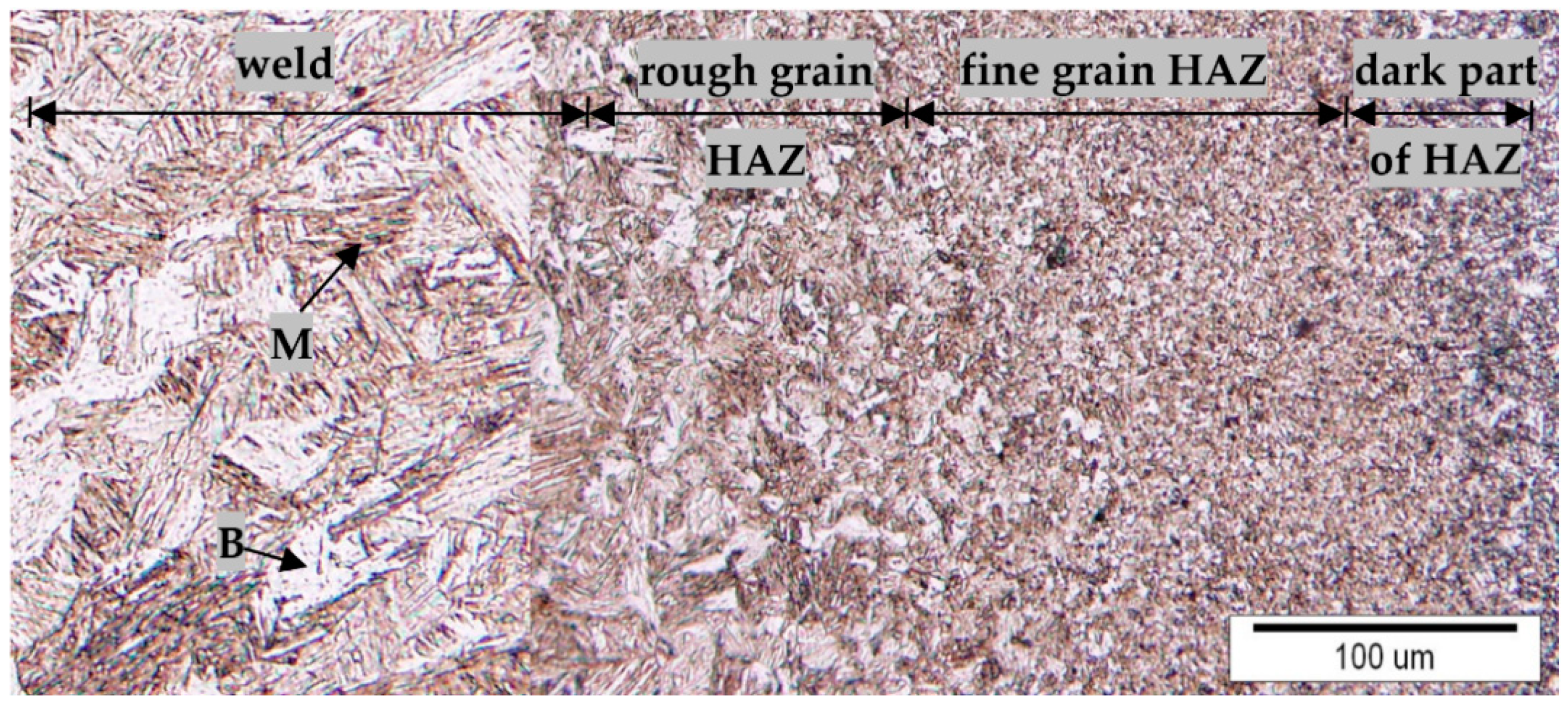
Figure 9 depict the cross-sectional microstructure along the weld obtained with welding speed of 0.6 m/min (energy input 300 J/cm). In the weld region is mainly martensitic with a small percentage of bainitic crystal grains. Martensitic microstructure is also present in the rough and fine grained part of HAZ. In the fine grained/ dark part HAZ transition zone proeutectoid ferrite was formed and here the hardness is decreased. In the dark part of HAZ the quantity of ferrite slightly increases, whereas the proeutectoid ferrite precipitated in the form of equiaxed polyhedron grains. As expected, similar to the previous samples, the base workpiece has microstructure of tempered martensite.
The microstructure of the weld produced using a welding speed of 0.8 m/min is mostly martensitic with a small amount of bainite, whereas the rough HAZ region (Figure 10) is quite narrow. On the left side of the Figure 10 a fine grained HAZ is obtained, where the microstructure is similar, only the crystal grains are approximately 6 μm large. This area is followed by the microstructure of proeutectoid ferrite with a smaller hardness.
Furthermore, by comparing Figure 9 and Figure 10 an obvious trend can clearly be observed, i.e., higher the heat input (lower the welding speed), larger the martensitic needles in the weld region and tempered martensitic grains in HAZ [13,23,26].
Figure 11 shows the effect of welding speed on the microstructural and mechanical properties on the carrying cross-section part of the weld. It can be seen that in the weld microstructure at welding speed of 0.2 m/min mostly acicular ferrite precipitated and on the crystal boundaries, allotriomorphic ferrite is present.
The weld hardness ranged from 201 to 250 HV5. At welding speed of 0.3 m/min the quantity of martensitic microstructure increases in the weld therefore hardness increases to about 347 HV5. Strong increase of martensitic microstructure is evident in specimen welded with the speed of 0.4 m/min where hardness increased also to the same value (347 HV5). There is also bainitic microstructure mixed with martensitic.
On the carrying cross-section of the weld there is about 70% of martensitic microstructure and 30% of bainitic microstructure obtained at welding speed between 0.6 m/min and 0.7 m/min. At this welding parameters the highest tensile-shear strength (945 MPa) of the weld was achieved. At welding speed above 0.8 m/min the tensile-shear strength was zero due to the insufficient fusion. The reason for this was that the welding speed was too high and linear heat input too small to obtain the proper fusion between metal sheets.
Metallographic examinations clearly confirmed that specimens welded with lower welding speed with higher linear heat input have microstructure with acicular (ACF) and allotriomorphic ferrite (ALF). ACF is clearly evident in the root of the weld processed at speed of 0.18 m/min. (Figure 12). Magnified view in Figure 12b depicts that ALF precipitated along the crystal boundaries of ACF.
The welds at carrying cross section for welding speeds 0.2 m/min and 0.6 m/min were examined using a JSM-5610 Scanning Electron Microscopy (SEM, Jeol, Tokyo, Japan) microscope equipped with EDS microanalysis hardware. Microstructure of the weld welded with the speed of 0.2 m/min is mostly acicular ferrite (ACF) with a small amount of widmanstätten ferrite (WF, Figure 13a), whereas the microstructure of the weld welded with the speed of 0.6 m/min is martensitic (Figure 13b). Microstructural results obtained in our study are consistent with those reported by other authors [13,18,23,26] concerning the application of laser welding of AHSS steels.
In this research we came to the conclusion that martensitic microstructure is precipitated in the weld of martensitic high strength steel at the welding speed of 0.6 m/min. At lower welding speeds there is also acicular and allotriomorphic ferrite precipitated along with the martensitic microstructure. Similar microstructures were observed by other authors that investigated the welding of AHSS [13,18,23,26]. The quantity of ACF and ALF increases as the welding speed decreases and they prevail at speeds lower than 0.2 m/min. With quantity of ACF, ALF, B and M, hardness and tensile-shear strength as well as elongation at break point are changing. By decreasing linear energy input (i.e., increasing welding speed) microstructure is changed into more martensitic due to higher cooling speed of the weld. This microstructure has higher hardness and tensile-shear strength, while the elongations are smaller.
4. Conclusions
In the present study, we investigated the effects of various remote laser welding parameters on high strength martensitic steel. Based on the research conducted, where the effect of different welding parameters on weld characteristics, mechanical and microstructural properties were investigated, the following conclusion can be drawn:
- The gap width in laser lap welding has a high influence on repeatability of welds. The gap must be avoided or reduced as much as possible for successful fusion. Small gaps can be ensured by using appropriate clamping.
- Optimal laser welding parameters were determined based on tensile-shear strength. The highest tensile-shear strength of 945 MPa, and the weld hardness of 396 HV5, being almost the similar as the hardness of the base material (400 HV5), was achieved at a laser power of 300 W and at a welding speed of 0.6 m/min. Such welds are suitable for static applications.
- Optimal laser welding parameters for dynamical loading were obtained at welding speeds between 0.18–0.3 mm/min at a constant laser power of 300 W. These welds have a proper visual appearance and suitable cross-sectional microstructure. The obtained welds have wider weld carrying cross section and elongations between 7% and 11%. Microstructure predominately consists of acicular ferrite, and smaller amount of allotriomorphic ferrite, bainite and martensite.
- Weld microstructures obtained at welding speeds of up to 0.2 m/min, consist predominately of acicular ferrite and allotriomorphic ferrite, which precipitated along its borders. Hence, the obtained hardness is low and ranging from 200 to 250 HV5. With higher welding speeds, i.e., 0.3 m/min and above, martensitic grains evolved, thus increase in hardness and tensile-shear strength was observed.
- Weld joints with highest tensile-shear strength exhibit pronounced martensitic and bainitic microstructure. For example, at welding speed of 0.6 and 0.7 m/min, the microstructural ratio between martensite and bainite is approximately 70/30. This contributed to increased strength and reduced strain at the breaking point of the weld carrying cross-sections.
Author Contributions
Conceptualization, U.T., M.P. and D.K.; data curation, U.P.; formal analysis, U.P. and M.P.T.; investigation, U.P. and M.P.T; methodology, U.T. and M.P.; project administration, D.K.; resources, M.J. and D.K.; supervision, D.K.; validation, U.T., M.P., M.J. and D.K.; writing-original draft, U.P. and M.P.T.; writing-review & editing, U.T., M.P. and D.K. All authors have read and agreed to the published version of the manuscript.
Funding
The authors acknowledge the financial support from the state budget by the Slovenian Research Agency Programme No. P2-0270 and projects No. L2-8181 and L2-8183.
Acknowledgments
The authors would also like to thank A. Nagode for the assistance with SEM measurements.
Conflicts of Interest
The authors declare no conflict of interest.
References
- Lesch, C.; Kwiaton, N.; Klose, F.B. Advanced High Strength Steels (AHSS) for Automotive Applications–Tailored Properties by Smart Microstructural Adjustments. Steel Res. Int. 2017, 10, 88. [Google Scholar] [CrossRef]
- Bhadeshia, H.K.D.H.; Honeycombe, R. Steels Microstructure and Properties, 3rd ed.; Elsevier Ltd.: Alpharetta, GA, USA, 2006. [Google Scholar]
- Gould, J.E.; Khurana, S.P.; Li, T. Predictions of Microstructures when Welding Automotive Advanced High-Strength Steels. Weld. J. 2006, 85, 111s–116s. [Google Scholar]
- De Cooman, B.C.; Speer, J.G. Quench and Partitioning Steel: A New AHSS Concept for Automotive Anti-Intrusion Applications. Steel Res. Int. 2006, 77, 634–640. [Google Scholar] [CrossRef]
- Steel Market Development Institute. Materials Competition in Automotive. Available online: http://automotive.arcelormittal.com/ (accessed on 28 December 2017).
- Jody, N. Hall (General Motors Company): Evolution of Advanced High Strength Steels in Automotive Applications. Available online: http://www.steelsustainability.org/ (accessed on 28 December 2017).
- Kwon, O.; Lee, K.; Kim, G.; Chin, K.G. New Trends in Advanced High Strength Steel Developments for Automotive Application. Mater. Sci. Forum 2010, 638–642, 136–141. [Google Scholar] [CrossRef]
- Jin, Y.S. Development of advanced high strength steels for automotive applications. La Metallurgia Italiana 2011, 6, 43–48. [Google Scholar]
- Branagan, D. The NanoSteel Company: Overview of a New Category of 3rd Generation AHSS. Available online: http://automotive.arcelormittal.com/ (accessed on 28 December 2017).
- De Guzman, J.J. The Influence of Hydrogen on MS980, MS1180, MS 1300 and MS1500 Martensitic Advanced High Strength Steels Used for Automotive Applications. Ph.D. Thesis, The School of Mechanical and Minin Engineering, University of Queensland, Brisbane, Australia, 2017. [Google Scholar]
- KEM Automobilkonstruktion. Schweißen Warmumgeformter Stähle im Karosseriebau von Volvo. Available online: http://automobilkonstruktion.industrie.de/karosserie-interieur/auf-die-kalte-art/ (accessed on 31 January 2017).
- Cora, Ö.N.; Koçe, M. Promises and problems of ultra/advanced high strength steel (U/AHSS) ultilization in automotive industry. In Proceedings of the 7th Automotive Technologies Congress, Bursa, Turkey, 26–27 May 2014; Hamad bin Khalifa University: Doha, State of Qatar; pp. 1–8. [Google Scholar]
- Gorka, J.; Ozgowicz, A.; Matusek, K. Robotic spot welding of DOCOL 1200M steel. Weld. Technol. Rev. 2019, R.91, 33–38. [Google Scholar] [CrossRef]
- Radwański, K.; Wroźyna, A.; Kuziak, R. Role of the advanced microstructures charactization in modelling of mechanical properties of AHSS steels. Mater. Sci. Eng. A 2015, 639, 567–574. [Google Scholar]
- Forouzan, F.; Vuorinen, E.; Mücklich, F. Post weld-treatment of laser welded AHSS by application of quenching and partitioning technique. Mater. Sci. Eng. A 2017, 698, 174–182. [Google Scholar] [CrossRef]
- Vanovsek, W.; Bernhard, C.; Filder, M.; Posch, G. Influence of aluminium content on the characterization of microstructure and inclusions in high-strength steel welds. Weld. World 2013, 57, 73–83. [Google Scholar] [CrossRef]
- Sperle, J.O.; Olsson, K. High Strength and Ultra High Strength Steels for Weight Reduction in Structural and Safety Related Applications; Saab Tunnplåt AB: Borlänge, Sweden, 2005; pp. 1–10. Available online: https://www.sperle.se/referenser/pdf/artiklar/V4_ISATA.pdf/ (accessed on 28 December 2019).
- Guo, W.; Li, L.; Crowther, D.; Dong, S.; Francis, J.A.; Thompson, A. Laser welding of high strength steels (S960 and S700) with medium thickness. J. Laser Appl. 2016, 28, 022425. [Google Scholar] [CrossRef]
- Keeler, S.; Kirnchi, M. Advanced High-Strength Steels Application Guidelines V6; WorldAutoSteel, World Steel Association: Brussels, Belgium, April 2017. [Google Scholar]
- SSAB. Docol AHSS for the Automotive Industry; Internal Company Documentation SSAB; SSAB: Stockholm, Sweden, 2016; Available online: https://www.ssab.com/products/brands/docol/products/docol-1200m (accessed on 28 December 2019).
- Oyyaravelu, R.; Kuppan, P.; Arivazhagan, N. Metallurgical and mechanical properties of laser welded high strength low alloy steel. J. Adv. Res. 2016, 7, 463–472. [Google Scholar] [CrossRef] [PubMed] [Green Version]
- Kim, C.; Kang, M.J.; Park, Y.D. Laser welding of Al–Si coated hot stamping steel. Procedia Eng. 2011, 10, 614–714. [Google Scholar] [CrossRef] [Green Version]
- Górka, J.; Ozgowicz, A. The structure and properties of laser seam stepper system (LSS) welded the low alloy high strength steel DOCOL 1200M with martensitic structure. Mater. Sci. Adv. Compos. Mater 2018, 2, 1–10. [Google Scholar] [CrossRef]
- Górka, J. Assessment of the effect of laser welding on the properties and structure of TMCP steel butt joints. Materials 2020, 13, 1312. [Google Scholar]
- Winczek, J.; Modrzycka, A.; Gawrońska, E. Analytical description of the temperature field induced by laser heat source with any trajectory. Procedia Eng. 2016, 149, 553–558. [Google Scholar] [CrossRef] [Green Version]
- Němeček, S.; Mužík, T. Differences between laser and arc welding of HSS steels. Phys. Procedia 2012, 39, 67–74. [Google Scholar]
- Popović, O.; Lukić, U.; Prokić, C.R.; Burzić, M.; Jovičić, R. The influence of heat input on the content of acicular ferrite in weld metal of microalloyed steel. In Proceedings of the 18th International Reserch/Expert Conference, TMT 2014, Budapest, Hungary, 10–12 September 2014; pp. 401–404. [Google Scholar]
- Katayama, S. Handbook of Laser Welding Technologies, 1st ed.; Woodhead Publishing: Cambridge, UK, 2013. [Google Scholar]
- Klobčar, D.; Tušek, J. An overview of use of laser technologies in the automotive industry. Ventil 2015, 21, 214–219. [Google Scholar]
- Davim, J.P. Lasers in Manufacturing; John Wiley & Sons: London, UK, 2012. [Google Scholar]
- Jezeršek, M.; Možina, J.; Diaci, J.; Kosler, H. System and Method for Laser Processing. EP15178871, 29 July 2015. [Google Scholar]
- Steen, W.M.; Mazumder, J. Laser Material Processing; Springer Science & Business Media: Berlin, Germany, 2010. [Google Scholar]
Figure 1.
Presentation of (a) jig for clamping the work pieces during laser welding and (b) specimen for tensile-shear testing.
Figure 1.
Presentation of (a) jig for clamping the work pieces during laser welding and (b) specimen for tensile-shear testing.

Figure 2.
Mascrosection of the weld with schematic presentation of hardness measurement positions: (a) 0.3 m/min, (b) 0.8 m/min.
Figure 2.
Mascrosection of the weld with schematic presentation of hardness measurement positions: (a) 0.3 m/min, (b) 0.8 m/min.

Figure 3.
Properties of Docol 1200 U/AHHS in as-delivered condition; (a) engineering stress-strain diagram of the specimens sectioned parallel and perpendicular to the rolling directions, (b) microstructure of the “as-delivered” condition.
Figure 3.
Properties of Docol 1200 U/AHHS in as-delivered condition; (a) engineering stress-strain diagram of the specimens sectioned parallel and perpendicular to the rolling directions, (b) microstructure of the “as-delivered” condition.

Figure 4.
Macrographic images of laser welded Docol 1200M samples at constant 300 W laser power: (a) welding speed from 0.2 to 1.0 m/min for lap joints from upper and bottom side and (b) welding speed from 0.15 to 1.0 m/min for macro section showing the penetration depth.
Figure 4.
Macrographic images of laser welded Docol 1200M samples at constant 300 W laser power: (a) welding speed from 0.2 to 1.0 m/min for lap joints from upper and bottom side and (b) welding speed from 0.15 to 1.0 m/min for macro section showing the penetration depth.

Figure 5.
Schematic presentation of the weld carrying cross-section surface determination.

Figure 6.
Hardness in direction from the weld centre to the base obtained at welding speeds (a) below 0.2 mm/min (b) from 0.3 to 0.6 m/min and (c) from 0.7 to 1.0 m/min.
Figure 6.
Hardness in direction from the weld centre to the base obtained at welding speeds (a) below 0.2 mm/min (b) from 0.3 to 0.6 m/min and (c) from 0.7 to 1.0 m/min.


Figure 7.
The effect of different welding speeds on the mechanical properties of the produced welds.
Figure 7.
The effect of different welding speeds on the mechanical properties of the produced welds.

Figure 8.
Microstructure of different weld region obtained at welding speed of 0.2 m/min.

Figure 9.
Microstructure of the weld and HAZ obtained at welding speed of 0.6 m/min.

Figure 10.
Microstructure of the weld and HAZ obtained at welding speed of 0.8 m/min.

Figure 11.
The effect of welding speed on the microstructure and hardness of the carrying part of the weld.
Figure 11.
The effect of welding speed on the microstructure and hardness of the carrying part of the weld.

Figure 12.
Microstructure (a) on the boundaries of HAZ/weld root, and (b) magnified view corresponding to the marked region in (a).
Figure 12.
Microstructure (a) on the boundaries of HAZ/weld root, and (b) magnified view corresponding to the marked region in (a).

Figure 13.
SEM microstructural observations: (a) 0.2 m/min, (b) 0.6 m/min; SEM.

© 2020 by the authors. Licensee MDPI, Basel, Switzerland. This article is an open access article distributed under the terms and conditions of the Creative Commons Attribution (CC BY) license (http://creativecommons.org/licenses/by/4.0/).
Share and Cite
MDPI and ACS Style
Prijanovič, U.; Prijanovič Tonkovič, M.; Trdan, U.; Pleterski, M.; Jezeršek, M.; Klobčar, D. Remote Fibre Laser Welding of Advanced High Strength Martensitic Steel. Metals 2020, 10, 533. https://doi.org/10.3390/met10040533
AMA Style
Prijanovič U, Prijanovič Tonkovič M, Trdan U, Pleterski M, Jezeršek M, Klobčar D. Remote Fibre Laser Welding of Advanced High Strength Martensitic Steel. Metals. 2020; 10(4):533. https://doi.org/10.3390/met10040533
Chicago/Turabian StylePrijanovič, Urban, Marica Prijanovič Tonkovič, Uroš Trdan, Matej Pleterski, Matija Jezeršek, and Damjan Klobčar. 2020. "Remote Fibre Laser Welding of Advanced High Strength Martensitic Steel" Metals 10, no. 4: 533. https://doi.org/10.3390/met10040533
Note that from the first issue of 2016, this journal uses article numbers instead of page numbers. See further details here.