Article

Effect of Short T6 Heat Treatment on the Thermal Conductivity and Mechanical Properties of Different Casting Processes Al-Si-Mg-Cu Alloys

Key Laboratory of Automobile Materials of Ministry of Education & School of Materials Science and Engineering, Nanling Campus, Jilin University, No. 5988 Renmin Street, Changchun 130025, China
*
Author to whom correspondence should be addressed.
Metals 2021, 11(9), 1450; https://doi.org/10.3390/met11091450
Submission received: 9 August 2021 / Revised: 1 September 2021 / Accepted: 8 September 2021 / Published: 13 September 2021

Abstract

:
The thermal conductivity of alloys is gradually becoming appreciated. It is often assumed that heat treatment can improve the thermal conductivity of Al-Si-Mg-Cu alloys, but there has been little relevant research. This paper studies the effects of different casting processes and short T6 heat treatment (ST6) on the thermal conductivity and mechanical properties of Al-Si-Mg-Cu alloys. The results show that a microstructure with fine α-Al crystal grains can be obtained by semi-solid die casting (SSDC), improving the mechanical properties of the Al-Si-Mg-Cu alloy in the as-cast state. After SSDC, the size and aspect ratio of eutectic silicon can be reduced by ST6 treatment, effectively improving the thermal conductivity and mechanical properties of the alloy. Finally, the influence of eutectic silicon on electron transport is analyzed in detail. With the SSDC + ST6 processing technology, Al-Si-Mg-Cu alloys with excellent thermal conductivity and mechanical properties can be obtained.

1. Introduction

With the popularization of 5G communication technology the construction of 5G base stations is in full swing, and with the acceleration of data transmission rates the resulting generation of heat is also increasing. Therefore, to ensure the stable operation of the base station and prevent work efficiency from being impaired by high-temperature frequency reduction, it is necessary to add a heat dissipation module for the equipment. Heat dissipating materials such as Al-Si alloys meet the requirements in terms of their mechanical properties and thermal conductivity while also being lightweight, therefore Al-Si alloy has been selected as the preferred material [1,2]. Al-Si alloy’s mechanical properties are excellent, but the thermal conductivity required for heat dissipation cannot meet requirements. Research by Lu et al. [3] shows that the methods used to strengthen metals usually lead to a decrease in electrical conductivity. Solute atoms and crystal structure defects improve metals’ mechanical strength and resistivity, so high strength and high conductivity are usually mutually exclusive [4,5,6].
Heat treatment and changes to the casting process are common means for controlling the microstructure. To date, the research on conventional heat treatment of Al-Si alloy has always been focused on improving mechanical properties [7,8,9,10]; there has been little research on the influence of electrical and thermal conductivity. Moreover, the conventional T6 heat treatment takes about 10 h to meet the performance requirements, resulting in long production cycles, high energy consumption and low efficiency. Although the heat treatment process is being continuously optimized, as with short-time T6 heat treatment, such optimization is still focused on mechanical properties [11,12]. Rometsch et al. [13] found that solution treatment at 540 °C for less than 1 h is enough to make permanent gravity mold casting A356 approach the maximum strength obtained after T6 heat treatment. Cai et al. [14] found that short-time solution treatment can also spheroidize eutectic silicon and uniformly distribute solute in the aluminum matrix of die-cast Al-Si alloy, while at the same time weakening the growth trend of α-Al grains. Studies by Menargues et al. [15] found that solutes can be uniformly distributed in the aluminum matrix after 0.5 h of solid solution, and that the mechanical properties of semi-solid cast A356 alloy obtained by T6 heat treatment with a solution time of 0.5 h are better than those obtained by conventional T6 heat treatment over longer times. Some studies have shown that aging processes can reduce the solute content in the alloy matrix and improve the electrical and thermal conductivity of the alloy [16,17]. However, there are few studies on the effect of short-term and long-term T6 heat treatment on the thermal conductivity of Al-Si alloy. Solution treatment makes solute dissolve into the Al matrix, and subsequent artificial aging precipitates the second phase, which reduces the degree of lattice distortion in the α-Al matrix and improves the thermal conductivity of the alloy. Therefore, it is necessary to study the influence of eutectic silicon size and morphology under different heat treatment conditions on the thermal/electrical conductivity of the alloy.
In this paper, the microstructure, mechanical properties, electrical conductivity and thermal conductivity of alloys from three casting processes are studied under T6 short time heat treatment and T6 long time heat treatment. As-cast alloys with excellent mechanical properties were obtained by three manufacturing processes. In order to study the effect of solution treatment time on the thermal conductivity and mechanical properties of the alloy, the same artificial aging treatment parameters were selected. The discussion of the influence of different casting and heat treatment processes on the microstructure and thermal conductivity of the alloy is of great theoretical significance when it comes to optimizing the production process and creating alloys with good thermal conductivity and mechanical properties.

2. Materials and Methods

In a resistance furnace (SG2-7-12, TIANYE Shanghai, China), industrial pure Al (99.8%), pure Mg (99.9%), Al-24.4%Si alloy, Al-50%Cu alloy, Al-10%Sr alloy and Al-3%B alloy were smelted. The melt was released into the steel mold to obtain a metal mold gravity casting alloy (GC). The melt was cooled to 690 °C and then injected into the pressure chamber of a die casting machine (YIZU-MI400T, YIZUMI, Foshan, China) through a 45 degrees inclined vibration channel at a rate of 40% to obtain a semi-solid die casting alloy (SSDC). The melt was kept at 690 °C and injected into the shot sleeve chamber, then injected into the mold to form a die-casting alloy (DC). The chemical composition of the alloy was measured with an optical emission spectrometer (ARL 4460, Thermo Fisher Scientific, Ecublens, Switzerland). Table 1 shows the chemical composition of the alloy.
The heat treatment was carried out in an air circulation resistance furnace (HOC-DH30D, HOCHECK, Shanghai, China). Alloys with different processes were subjected to both short T6 heat treatment (ST6), of 535 °C/0.5 h solution treatment + 170 °C/3 h artificial aging and long T6 heat treatment (LT6), of 535 °C/4 h solution treatment + 170 °C/3 h artificial aging. Tensile testing was carried out on a tensile tester (MTS-810, MTS, Eden Prairie, MN, USA) with a tensile speed of 0.6mm/min. Tensile data were obtained from at least three samples of each alloy. Grinding of the testing surface to 2000 grit and conductivity testing was performed at room temperature with a conductivity measuring instrument (Sigmatest 2.069, Foerster, Reutlingen, Germany). At least five positions were measured for each alloy. Research shows that the conductivity measurement method can characterize thermal conductivity [18], thus we can calculate the thermal conductivity according to the modified Widman-Franz law:
λ = LTσ + c,
in which λ is thermal conductivity, σ is electrical conductivity, T is temperature, L is the Lorenz number and c is 12.6 W/(m·K) [19,20,21].
The microstructure samples were taken from the middle of the tensile parts, which were roughly ground, finely ground, polished according to standard procedures, then etched in 1 vol.% HF solution. An optical microscope (OM; Carl Zeiss Ax-io-Imager-A2M, Göttingen, Germany) characterized the grain structure of the alloys. Image-Pro Plus 6.0 software adopting the linear intercept method (ASTM E112-2013) was used to measure the grain size of alloys GC, SSDC and DC after short time T6 heat treatment, and at least ten pictures for each alloy were measured to obtain the average grain size of each alloy. A scanning electron microscope (SEM; Carl Zeiss Evo-18, Göttingen, Germany) equipped with energy dispersive spectrometer (EDS) was used to characterized eutectic silicon. Eutectic silicon was measured, and at least ten pictures were measured for each alloy. The area sizes and aspect ratios of eutectic silicon were quantitatively analyzed.

3. Results and Discussion

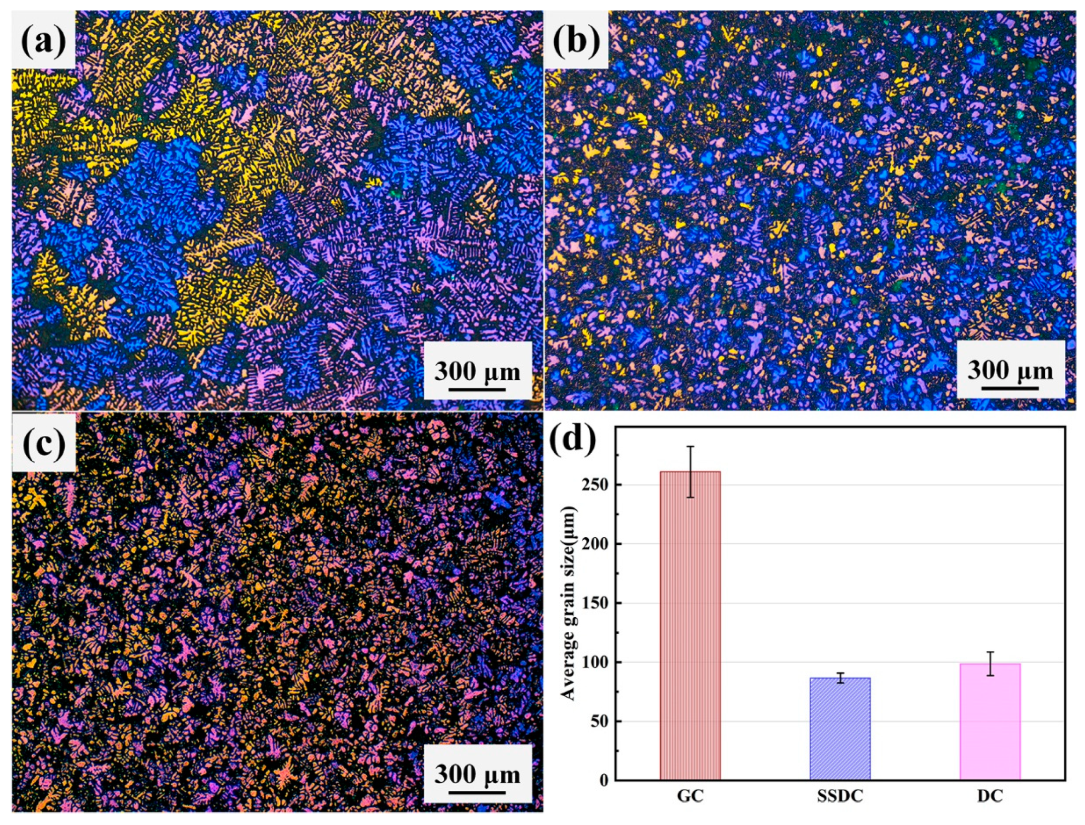
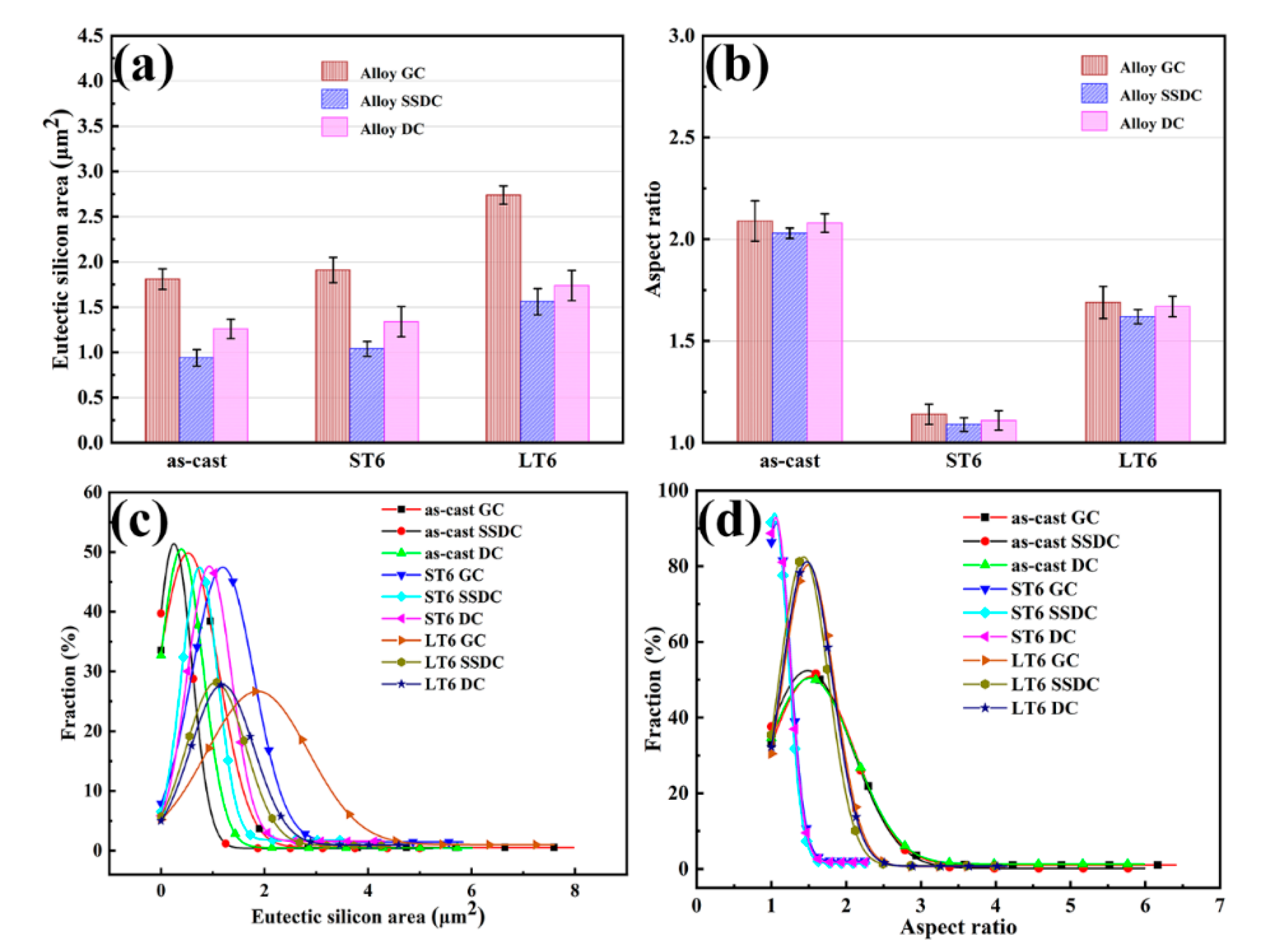
3.1. Microstructure of Alloy under Three Casting Processes

Figure 1 shows the as-cast polarized optical micrographs and average grain size diagrams of the GC, SSDC and DC alloys. It can be seen from Figure 1a,d that the α-Al grain size of alloy GC is coarse, with an average grain size of 260 μm. In Figure 1b,d it can be seen that alloy SSDC has fine and uniform α-Al grain size, with an average α-Al grain size of 86.6 μm. In Figure 1c,d the grain distribution of alloy DC is shown, with an average measured grain size of 98.7 μm. Due to the influence of different forming methods on the microstructure, the α-Al grain size and α-Al grain uniformity are different. Under the condition of gravity permanent mold casting the solidification rate is low, the dendrite has enough time to grow, and finally the coarse and uneven grain structure is obtained. The solidification rate is fast under die-casting, and although the dendrite growth is restrained, a microstructure with more refined grains and improved uniformity is finally obtained because of the anisotropy of dendrite growth. Semi-solid die-casting can form a finer microstructure, and through vibration and fast solidification rate greatly reduces unevenness in the microstructure caused by anisotropy of dendrite growth, thus obtaining a final microstructure with fine grain and high uniformity.
Figure 2 shows scanning electron microscope images of alloys GC, SSDC, and DC under as-cast, ST6, and LT6 treatments, respectively. As can be seen from Figure 2a, the as-cast structure image of alloy GC shows that the eutectic silicon is fibrous, but as indicated by the white arrow in the figure it can be seen that there are also large strips of eutectic silicon. Similar phenomena can also be seen in the as-cast microstructure of alloys SSDC and DC in Figure 2d,g. This is due to the residue of long strip eutectic silicon during the modification process. Figure 2b shows the microstructure of the eutectic silicon after alloy GC was treated with ST6. It can be seen in the image that the eutectic silicon is spherical, which is consistent with the previous conclusion [13]. The same phenomenon can also be seen in Figure 2e,h, which indicates that the eutectic silicon phases of different casting processes have the same response under ST6 treatment. Figure 2c shows the microstructure of alloy GC after LT6 treatment. The image shows that the eutectic silicon phase coarsens and takes shape irregularly; it even shows two adjacent eutectic silicon particles growing together, making the eutectic silicon larger in size (indicated by the white arrow in the figure). Since the atomic arrangement on the contact surface between eutectic silicon particles is consistent and matching, and meets the requirements of crystal growth, adjacent eutectic silicon particles tend to aggregate and overlap in order to further reduce the interface energy [22]. The same phenomenon can be seen in Figure 2f,i.
Figure 3 is the eutectic silicon size, aspect ratio and corresponding frequency Gaussian fitting distribution of alloys GC, SSDC and DC in the as-cast, ST6 and LT6 treatment states. Table 2 shows the eutectic silicon size and aspect ratio of the alloy in detail. The area size is used to characterize the size of eutectic silicon (the size of eutectic silicon appearing in this paper is its average area size unless otherwise stated). As can be seen from Figure 3a, the eutectic silicon size of alloy SSDC is the smallest in the as-cast state, while the eutectic silicon size of alloy GC is the largest. Compared with the traditional casting process, alloy SSDC has a faster cooling rate and smaller α-Al grain size. The smaller α-Al grain size reduces the aggregation of eutectic silicon and restricts the growth of eutectic silicon to some extent. At the same time, its structure is more uniform, and the second phase near the eutectic microscopic components shows a smaller size around the matrix [15]. The combined effect of these factors makes alloy SSDC in the as-cast state have a smaller eutectic silicon size. After ST6 treatment, the eutectic silicon size of the three alloys increases slightly. During the short-term solution treatment the diffusion rate of atoms increases, which leads to the breakage of long eutectic silicon particles. The distortion energy of sharp edges or sharp corners of fibrous eutectic silicon particles is higher, which further leads to the fracture of long eutectic silicon particles [23]. Meanwhile, the smaller silicon particles in the alloy gather on the larger eutectic silicon during solution treatment, which leads to the growth of eutectic silicon particles. After LT6 treatment, the silicon particle size of the three alloys increased significantly. On the one hand, as the solution time increases and in order to reduce the surface energy small eutectic silicon particles are attached to the larger eutectic silicon particles by diffusion; on the other hand, the coarsened eutectic silicon particles grow together. These factors cause the coarsening of the eutectic silicon particles. From Figure 3c, we can see the change in eutectic silicon area distribution from the as-cast state to the ST6 state and then to the LT6 state. From the as-cast state to the ST6 state the apex of the curve moves to the right, the number of small eutectic silicon particles decreases, and the large eutectic silicon disappears. This shows that the eutectic silicon with small size diffuses to the vicinity of the eutectic silicon with large size and gathers and grows there, while the eutectic silicon with larger size is broken. From the ST6 to the LT6 treatment state the vertex of the curve continues to move to the right, and the eutectic silicon with small size almost disappears, while the eutectic silicon with large size reappears. This shows that with increasing solution treatment time the aggregation and growth of small- and large-sized eutectic silicon particles continues to occur and a part of the grown eutectic silicon particles grow together. It can be seen from Figure 3b that the average aspect ratios of the three alloys under as-cast conditions have little difference (with a value of about 2), indicating that the eutectic silicon is in the shape of irregular strips. After ST6 treatment, the aspect ratio of eutectic silicon drops to about 1.1, indicating that its morphology is nearly spherical. This is because in order to further reduce the surface energy, particles are spheroidized when diffusion and dissolution reach equilibrium. After LT6 treatment, the aspect ratio of eutectic silicon increases to about 1.65, reflecting the possibility for adjacent eutectic silicon particles to grow together during the coarsening process with the extension of the solid solution time. It can be seen from Figure 3d that there is little difference in the frequency of the aspect ratio of the three alloys in different states, which reflects that the change trend of eutectic silicon in the heat treatment process of the alloys with different casting processes is basically the same. In the ST6 state, the frequency of the aspect ratio close to 1 is very high, indicating that most of the eutectic silicon at this time is close to spherical. The frequency of low aspect ratio decreased after LT6 treatment, but it was still higher than in the as-cast state. Since the preferred growth direction of eutectic silicon is the <112> crystal orientation on the {111} crystal plane, Si atoms grow uniformly along the six preferred orientations of the (111) plane. Therefore, the eutectic silicon is coarsened and the overlapping phenomenon of adjacent eutectic silicon occurs when it grows to a certain extent. The former phenomenon leads to an increase in the size of the eutectic silicon, and the latter leads to an increase in the aspect ratio.

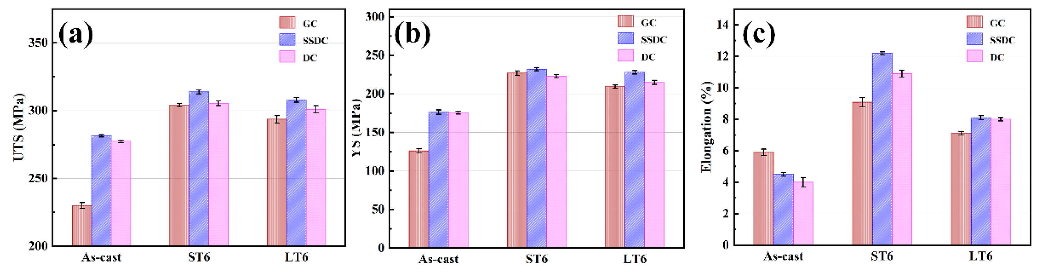
3.2. Mechanical Properties of Alloys under Three Casting Processes

Figure 4 and Table 3 show the tensile results of the three alloys: ultimate tensile strength (UTS), yield strength (YS), and elongation. It can be seen from Figure 4a,b that the UTS and YS of alloy SSDC are the highest in all three states, which is mainly due to the small grain size as the fine grain can form fine grain strengthening. The ST6 treatment effectively promoted the diffusion and migration of the eutectic phase and made the eutectic phase uniform [24]. Moreover, strength and elongation are remarkably improved. With the extension of the solution treatment time, the three alloys’ tensile strength first increased and then decreased, because the spheroidization and homogenization of eutectic silicon can reduce the splitting effect on the matrix and improve the mechanical properties of the alloy. The eutectic silicon in the ST6 treatment is basically spherical, and the splitting effect on the matrix is very low. With the extension of the solution treatment time, the aspect ratio of eutectic silicon to diameter increases and gradually becomes irregular, affecting the alloy’s strength according to the Griffith’s theory, described as Formula (2) [25]:
σc = kcd−1/2,
where kc is the fracture toughness of the particles and d is the average diameter of the particle. Therefore, compared with the as-cast and LT6 states, eutectic silicon in the ST6 state is relatively fine, which can promote higher fracture stress. Figure 4c shows that the elongation of alloy GC in the as-cast state is the highest at 5.9%, while the elongation of alloy DC is the lowest at 4%. This may be due to the stress concentration of alloys SSDC and DC during the casting process resulting in a decrease in elongation. The elongation of GC, SSDC and DC increases to 9.08%, 10.9% and 12.19% after ST6 treatment, respectively. The increase in elongation is due to the spheroidization and homogenization of eutectic silicon, which reduces the splitting effect on the matrix and eliminates stress defects. After LT6 treatment the elongation of all three process alloys decreased, and the elongation of alloy SSDC decreased to 8.1%. This is due to the decrease of elongation caused by the coarsening of eutectic silicon and the hindrance of dislocation migration with the extension of the solution time.
Figure 5 is an SEM picture of the tensile fracture morphology of the alloys. It can be seen from Figure 5a that the number of fracture dimples in the as-cast state is very small. As can be seen from Figure 5b–d, there are many fine dimples, indicating that they are all ductile fractures. This is because the spheroidization of eutectic silicon during solution treatment makes the alloy have higher plasticity after heat treatment [26]. With the decrease of the aspect ratio of eutectic silicon from the as-cast state to the ST6 state, there is an obvious increase in the number of fine dimples. Compared with the other two alloys, the number of fine dimples in alloy SSDC is clearly larger, and the plasticity is also the best [27].

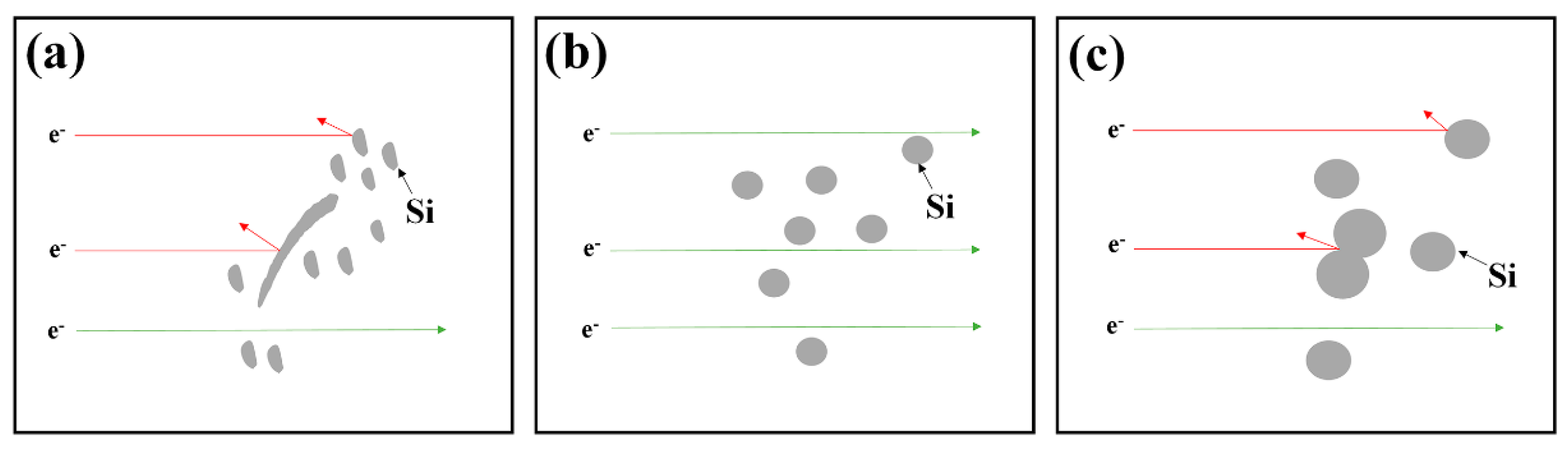
3.3. Electrical and Thermal Conductivity of Alloys under Three Casting Processes

Figure 6 shows the three alloys’ electrical conductivity and thermal conductivity under as-cast, ST6 and LT6 treatments, and Table 4 shows the detailed values. It can be seen from Figure 6a,b that alloy SSDC has the highest electrical and thermal conductivity under the as-cast conditions of the three processes, reaching 37.9% IACS and 159.6 W/(m·K), respectively. Vandersluis et al. [28] showed that grain size has little effect on thermal conductivity, so the main factor affecting the thermal conductivity of the alloy in the as-cast state was the morphology and size of eutectic silicon. The electrical conductivity and thermal conductivity of the three alloys were improved by the ST6 treatment. The electrical conductivity and thermal conductivity of alloy SSDC reached 42.3%IACS and 176.4 W/(m·K). Under the conditions of ST6 treatment the aspect ratio of the alloy was greatly diminished, reducing the obstacle of electron flow, increasing the electron transfer rate, and improving the electrical and thermal conductivity of the alloy [29]. After LT6 heat treatment, the electrical and thermal conductivity of the three alloys decreased. With the prolongation of the solution time the size and length-diameter ratio of eutectic silicon increased, resulting in enhanced electron scattering, reduced electron channels, and decreased electrical and thermal conductivity. The heat transfer between metals and alloys is essentially that electrons drift from relatively hot areas to relatively cold areas, resulting in the conduction of heat energy [30]. The changes to the microstructure of the alloys studied in this paper can effectively promote the electron drift process: in the process of solution treatment eutectic silicon particles are rapidly broken and spheroidized, and the same artificial aging process causes solute precipitation in the matrix, thus the heat transfer process of electrons is improved [31].
Figure 7 is a schematic diagram of free electron transport in different states. Figure 7a shows that the main reasons for the low as-cast thermal conductivity are the presence of strip eutectic silicon in the alloy and the electron scattering caused by the aggregation of eutectic silicon. Figure 7b shows that the spheroidization of eutectic silicon greatly increases the electron pass rate under ST6 treatment. Figure 7c shows that under LT6 treatment, with the extension of the solution time, silicon atoms continue to diffuse, thus increasing the size of eutectic silicon, resulting in adjacent eutectic silicon particles growing together. This blocks the transfer of free electrons, resulting in a decrease in thermal conductivity.

4. Conclusions

In this paper, the combined effects of different casting processes and heat treatments on the microstructure, thermal conductivity and mechanical properties of Al-Si-Mg-Cu alloy were investigated. Compared with the GC and DC processes, the grain size of α-Al in the SSDC process was reduced to 86.6 μm, and the UTS value of as-cast Al-Si-Mg-Cu alloys increased to 281.4 MPa. Compared with as-cast Al-Si-Mg-Cu alloys using the three aforementioned casting processes, the subsequent ST6 and LT6 treatments improved the thermal conductivity and mechanical properties of the alloys, with the properties of the alloys in the ST6 state being better than those in the LT6 state. Under the same aging conditions, the thermal conductivity of the alloys was mainly affected by the morphology and size of eutectic silicon. Short-time solid solution in the ST6 treatment process makes eutectic silicon spheroidized and the effective time of silicon atom diffusion is short, preventing the further growth of eutectic silicon and reducing obstacles for free electrons in the transmission process and thereby improving thermal conductivity. With the SSDC + ST6 process the thermal conductivity, UTS and elongation of Al-Si-Mg-Cu alloys can be increased to 176.4 W/(m·K), 313.87 MPa and 12.19%, respectively. Therefore, the Al-Si-Mg-Cu alloys treated by the SSDC + ST6 process can simultaneously obtain excellent thermal conductivity and excellent mechanical properties.

Author Contributions

Conceptualization, Z.-Q.D. and R.-F.Y.; methodology, Z.-Q.D., P.-K.M., R.-F.Y. and J.-G.W.; software, Z.-Q.D., P.Z., P.-K.M., Z.-J.L. and T.-S.L.; validation, Z.-Q.D., P.Z., P.-K.M., Z.-J.L. and T.-S.L.; investigation, Z.-Q.D., Z.-P.G., P.Z., Z.-J.L. and T.-S.L.; writing—original draft preparation, Z.-Q.D.; writing—review and editing, Z.-Q.D., R.-F.Y. and J.-G.W.; supervision, R.-F.Y., Z.-P.G. and P.-K.M.; project administration, J.-G.W. and Z.-P.G.; funding acquisition, J.-G.W. All authors have read and agreed to the published version of the manuscript.

Funding

This research was funded by the National Key Research and Development Program of China (Grant No. 2018YFB2001801).

Conflicts of Interest

The authors declare no conflict of interest.

References

  1. Sauvage, X.; Bobruk, E.V.; Murashkin, M.Y.; Nasedkina, Y.; Enikeev, N.A.; Valiev, R.Z. Optimization of electrical conductivity and strength combination by structure design at the nanoscale in Al–Mg–Si alloys. Acta Mater. 2015, 98, 355–366. [Google Scholar] [CrossRef]
  2. Kim, Y.-M.; Choi, S.-W.; Hong, S.-K. The behavior of thermal diffusivity change according to the heat treatment in Al-Si binary system. J. Alloys Compd. 2016, 687, 54–58. [Google Scholar] [CrossRef]
  3. Lu, L.; Shen, Y.; Chen, X.; Qian, L.; Lu, K. Ultrahigh Strength and High Electrical Conductivity in Copper. Science 2004, 304, 422. [Google Scholar] [CrossRef] [PubMed] [Green Version]
  4. Valiev, R.Z.; Murashkin, M.Y.; Sabirov, I. A nanostructural design to produce high-strength Al alloys with enhanced electrical conductivity. Scr. Mater. 2014, 76, 13–16. [Google Scholar] [CrossRef]
  5. Miyake, J.; Fine, M.E. Electrical conductivity versus strength in a precipitation hardened alloy. Acta Metall. Mater. 1992, 40, 733–741. [Google Scholar] [CrossRef]
  6. Sakai, Y.; Inoue, K.; Asano, T.; Wada, H.; Maeda, H. Development of high-strength, high-conductivity Cu-Ag alloys for high-field pulsed magnet use. Appl. Phys. Lett. 1991, 59, 2965–2967. [Google Scholar] [CrossRef]
  7. Alfonso, I.; Maldonado, C.; Gonzalez, G.; Bedolla, A. Effect of Mg content and solution treatment on the microstructure of Al-Si-Cu-Mg alloys. J. Mater. Sci. 2006, 41, 1945–1952. [Google Scholar] [CrossRef]
  8. Eisaabadi, B.G.; Yeom, G.Y.; Tiryakioğlu, M.; Netto, N.; Beygi, R.; Mehrizi, M.Z.; Kim, S.K. The effect of solution treatment time on the microstructure and ductility of naturally-aged A383 alloy die castings. Mater. Sci. Eng. A 2018, 722, 1–7. [Google Scholar] [CrossRef]
  9. Choi, S.-W.; Kim, Y.-M.; Kim, Y.-C.; Kang, C.-S. Effects of alloying elements on mechanical and thermal characteristics of Al-6wt-%Si-0.4wt-%Mg–(Cu) foundry alloys. Mater. Sci. Technol. 2019, 35, 1365–1371. [Google Scholar] [CrossRef]
  10. Beroual, S.; Boumerzoug, Z.; Paillard, P.; Borjon-Piron, Y. Effects of heat treatment and addition of small amounts of Cu and Mg on the microstructure and mechanical properties of Al-Si-Cu and Al-Si-Mg cast alloys. J. Alloys Compd. 2019, 784, 1026–1035. [Google Scholar] [CrossRef]
  11. Zhang, D.L.; Zheng, L.H.; StJohn, D.H. Effect of a short solution treatment time on microstructure and mechanical properties of modified Al–7wt.%Si–0.3wt.%Mg alloy. J. Light Met. 2002, 2, 27–36. [Google Scholar] [CrossRef]
  12. Pedersen, L.; Arnberg, L. The effect of solution heat treatment and quenching rates on mechanical properties and microstructures in AlSiMg foundry alloys. Metall. Mater. Trans. A Phys. Metall. Mater. Sci. 2001, 32, 525–532. [Google Scholar] [CrossRef]
  13. Rometsch, P.A.; Arnberg, L.; Zhang, D.L. Modelling dissolution of Mg2Si and homogenisation in Al-Si-Mg casting alloys. Int. J. Cast Met. Res. 2016, 12, 1–8. [Google Scholar] [CrossRef]
  14. Cai, Q.; Mendis, C.L.; Chang, I.T.H.; Fan, Z. Effect of short T6 heat treatment on the microstructure and the mechanical properties of newly developed die-cast Al–Si–Mg–Mn alloys. Mater. Sci. Eng. A 2020, 788. [Google Scholar] [CrossRef]
  15. Menargues, S.; Martín, E.; Baile, M.T.; Picas, J.A. New short T6 heat treatments for aluminium silicon alloys obtained by semisolid forming. Mater. Sci. Eng. A 2015, 621, 236–242. [Google Scholar] [CrossRef]
  16. Choi, S.W.; Cho, H.S.; Kang, C.S.; Kumai, S. Precipitation dependence of thermal properties for Al–Si–Mg–Cu–(Ti) alloy with various heat treatment. J. Alloys Compd. 2015, 647, 1091–1097. [Google Scholar] [CrossRef]
  17. Lados, D.A.; Apelian, D.; Wang, L. Solution Treatment Effects on Microstructure and Mechanical Properties of Al-(1 to 13 pct)Si-Mg Cast Alloys. Metall. Mater. Trans. B 2010, 42, 171–180. [Google Scholar] [CrossRef] [Green Version]
  18. Vandersluis, E.; Ravindran, C. Effects of solution heat treatment time on the as-quenched microstructure, hardness and electrical conductivity of B319 aluminum alloy. J. Alloys Compd. 2020, 838. [Google Scholar] [CrossRef]
  19. Cho, Y.H.; Kim, H.W.; Lee, J.M.; Kim, M.S. A new approach to the design of a low Si-added Al–Si casting alloy for optimising thermal conductivity and fluidity. J. Mater. Sci. 2015, 50, 7271–7281. [Google Scholar] [CrossRef]
  20. Lumley, R.N.; Deeva, N.; Larsen, R.; Gembarovic, J.; Freeman, J. The Role of Alloy Composition and T7 Heat Treatment in Enhancing Thermal Conductivity of Aluminum High Pressure Diecastings. Metall. Mater. Trans. A 2012, 44, 1074–1086. [Google Scholar] [CrossRef]
  21. Olafsson, P.; Sandstrom, R.; Karlsson, Å. Comparison of experimental, calculated and observed values for electrical and thermal conductivity of aluminium alloys. J. Mater. Sci. 1997, 32, 4383–4390. [Google Scholar] [CrossRef]
  22. Lin, Y.C.; Luo, S.-C.; Huang, J.; Yin, L.-X.; Jiang, X.-Y. Effects of solution treatment on microstructures and micro-hardness of a Sr-modified Al-Si-Mg alloy. Mater. Sci. Eng. A 2018, 725, 530–540. [Google Scholar] [CrossRef]
  23. Shivkumar, S.; Ricci, S.; Keller, C.; Apelian, D. Effect of solution treatment parameters on tensile properties of cast aluminum alloys. J. Heat Treat. 1990, 8, 63–70. [Google Scholar] [CrossRef]
  24. Zhang, B.; Zhang, L.; Wang, Z.; Gao, A. Achievement of High Strength and Ductility in Al-Si-Cu-Mg Alloys by Intermediate Phase Optimization in As-Cast and Heat Treatment Conditions. Materials 2020, 13, 647. [Google Scholar] [CrossRef] [Green Version]
  25. Jiang, W.; Xu, X.; Zhao, Y.; Wang, Z.; Wu, C.; Pan, D.; Meng, Z. Effect of the addition of Sr modifier in different conditions on microstructure and mechanical properties of T6 treated Al-Mg2Si in-situ composite. Mater. Sci. Eng. A 2018, 721, 263–273. [Google Scholar] [CrossRef]
  26. Dong, X.; Yang, H.; Zhu, X.; Ji, S. High strength and ductility aluminium alloy processed by high pressure die casting. J. Alloys Compd. 2019, 773, 86–96. [Google Scholar] [CrossRef]
  27. Chawla, N.; Shen, Y.L. Mechanical Behavior of Particle Reinforced Metal Matrix Composites. Adv. Eng. Mater. 2001, 3, 357–370. [Google Scholar] [CrossRef]
  28. Vandersluis, E.; Ravindran, C. Influence of solidification rate on the microstructure, mechanical properties, and thermal conductivity of cast A319 Al alloy. J. Mater. Sci. 2019, 54, 4325–4339. [Google Scholar] [CrossRef]
  29. Cui, X.; Cui, H.; Wu, Y.; Liu, X. The improvement of electrical conductivity of hypoeutectic Al-Si alloys achieved by composite melt treatment. J. Alloys Compd. 2019, 788, 1322–1328. [Google Scholar] [CrossRef]
  30. Choi, S.W.; Kim, Y.M.; Lee, K.M.; Cho, H.S.; Hong, S.K.; Kim, Y.C.; Kang, C.S.; Kumai, S. The effects of cooling rate and heat treatment on mechanical and thermal characteristics of Al–Si–Cu–Mg foundry alloys. J. Alloys Compd. 2014, 617, 654–659. [Google Scholar] [CrossRef]
  31. Lumley, R.N.; Polmear, I.J.; Groot, H.; Ferrier, J. Thermal characteristics of heat-treated aluminum high-pressure die-castings. Scr. Mater. 2008, 58, 1006–1009. [Google Scholar] [CrossRef]
Figure 1. As-cast microstructure of polarized optical microscope: (a) alloy GC, (b) alloy SSDC, (c) alloy DC and (d) average grain size.
Metals 11 01450 g001
Figure 2. SEM of alloy GC (a) as-cast (b) ST6 (c) LT6, alloy SSDC:(d) as-cast (e) ST6 (f) LT6, and alloy DC: (g) as-cast (h) ST6 (i) LT6.
Metals 11 01450 g002
Figure 3. Alloys in different states: (a) average eutectic silicon area, (b) average aspect ratio of eutectic silicon, (c) Gaussian fitting of size frequency of eutectic silicon, (d) Gaussian fitting of eutectic silicon aspect ratio frequency.
Metals 11 01450 g003
Figure 4. Mechanical properties of the alloys: (a) UTS, (b) YS, (c) Elongation.
Metals 11 01450 g004
Figure 5. Tensile fracture morphology of (a) as-cast alloy GC, ST6 treatment; (b) alloy GC; (c) alloy SSDC; (d) alloy DC.
Metals 11 01450 g005
Figure 6. Alloys in different states: (a) electrical conductivity (b) thermal conductivity.
Metals 11 01450 g006
Figure 7. Schematic diagram of electron transmission in different states: (a) as-cast (b) ST6 (c) LT6.
Metals 11 01450 g007
Table 1. Chemical composition of Al-Si-Mg-Cu alloy (wt.%).
SiCuMgFeSrBAl
7.9330.0990.5120.5510.0800.010Bal.
Table 2. Si area sizes and aspect ratio of Si particles.
AlloyStatusArea Size (μm2)Aspect Ratio
As-cast1.812.09
GCST61.911.14
LT62.741.69
As-cast0.942.03
SSDCST61.041.09
LT61.561.62
As-cast1.262.08
DCST61.341.11
LT61.741.67
Table 3. Mechanical properties of the alloys.
AlloyStatusUTS (MPa)YS (MPa)Elongation (%)
As-cast230.1 ± 2.1126.1 ± 2.75.9 ± 0.21
GCST6304 ± 1.2227 ± 2.89.08 ± 0.32
LT6293.7 ± 2.7209.4 ± 2.17.8 ± 0.11
As-cast281.4 ± 0.9176.5 ± 2.84.5 ± 0.12
SSDCST6313.87 ± 1.5232 ± 212.19 ± 0.09
LT6308 ± 1.8228 ± 2.28.1 ± 0.13
As-cast279.4 ± 0.9175.8 ± 24 ± 0.30
DCST6305.4 ± 1.7223 ± 2.110.9 ± 0.22
LT6301 ± 2.7215 ± 2.68 ± 0.11
Table 4. Electrical and thermal conductivity of the alloys.
AlloyStatusElectrical Conductivity (% IACS)Thermal Conductivity (W/(m·K))
As-cast36.24 ± 0.18152.9 ± 0.69
GCST640.96 ± 0.19171.2 ± 0.82
LT638.79 ± 0.18162.7 ± 0.68
As-cast37.94 ± 0.13159.6 ± 0.48
SSDCST642.31 ± 0.2176.4 ± 0.76
LT640.52 ± 0.19169.6 ± 0.73
As-cast37.07 ± 0.1156.2 ± 0.42
DCST641.78 ± 0.1174.4 ± 0.39
LT639.78 ± 0.17166.6 ± 0.65
Publisher’s Note: MDPI stays neutral with regard to jurisdictional claims in published maps and institutional affiliations.

