
Study of the Thermal History upon Residual Stresses during the Dry Drilling of Inconel 718
by

Kévin Chenegrin
1,*, 
Denis Bouscaud
2,
Mathieu Girinon
3,
Habib Karaouni
4,
Jean-Michel Bergheau
1 and
Eric Feulvarch
1 1
LTDS, UMR 5513 CNRS, Ecole Nationale d’Ingénieurs de Saint-Etienne, Université de Lyon, 42023 Saint-Etienne, France
2
Laboratoire d’Étude des Microstructures et de Mécanique des Matériaux LEM3 (UMR CNRS 7239), Arts et Métiers ParisTech, Université de Lorraine, 4 Rue Augustin Fresnel, 57078 Metz, France
3
Technical Centre for Mechanical Industry (CETIM), 7 Rue de la Presse, 42952 Saint-Etienne, France
4
SAFRAN Tech, Rue des Jeunes Bois, 78772 Magny-les-Hameaux, France
*
Author to whom correspondence should be addressed.
Metals 2022, 12(2), 305; https://doi.org/10.3390/met12020305
Submission received: 6 January 2022
/
Revised: 31 January 2022
/
Accepted: 7 February 2022
/
Published: 10 February 2022
(This article belongs to the Special Issue Computational Methods in Metal Manufacturing Processes)
Abstract
:The main objective of this article was to show for the first time that heat transfer plays a major role in residual stress generation during the dry drilling of Inconel 718, and to propose a numerical strategy capable of simulating such thermo-mechanical phenomena. An X-ray diffraction (XRD) analysis shows that without lubrication, high tensile residual stresses can be observed on the surface of a deep through drilled hole. Such a situation can be highly detrimental for the fatigue lifetime of a mechanical component. A thermal history in five phases is first identified by means of temperature measurements exhibiting an overheating of approximately 500 C on the created hole surface just before the end of the drilling operation. A 3D thermo-viscoplastic model is herein improved in terms of boundary conditions to show that this phenomenon is triggered by the progressive decrease in the Inconel 718 volume under the cutting zone. To the authors’ knowledge, such a phenomenon has never been reported and simulated before in the literature. Then, a 3D thermo-elasto-plastic simulation including elasticity is proposed to compute residual stresses from the thermal results of the previous model. It shows for the first time that the overheating stage induces sufficiently intense plasticity to produce high tensile residual stresses of approximately 900 MPa as we experimentally observed.
1. Introduction
Drilling is widely used in the aeronautic industry for high-value components made of the Inconel 718 superalloy which has excellent mechanical properties until 650 C. Its understanding is therefore essential from an industrial perspective. Nevertheless, the thermo-mechanical impact of drilling on the hole surface has been the subject of very few scientific studies in recent years compared to milling, turning or welding processes, whereas this process can also have a strong influence on the resistance of mechanical components. For example, drilling residual stresses can modify the cyclic evolution of the critical plane normal stress [1], which is an important parameter for lifetime estimation [2], especially for high-cycle fatigue [3].
Therefore, the study of thermo-mechanical mechanisms induced by drilling is of great interest to understand how residual stresses are generated on the hole surface and how the process parameters can be optimized. According to the work of Dudzinski et al. [4] and Wolf et al. [5], the low thermal conductivity of Inconel 718 induces a concentration of heat in the cutting zone. The coupling of this phenomenon with the significant hardening of Inconel 718 for high temperatures leads to increased friction with the tool as reported by Sarikaya et al. [6]. Moreover, the high nickel content of this superalloy frequently induces chip adhesion on the tool. Due to the characteristics of Inconel 718, heat transfer can play an important role in the mechanisms of residual stress generation in dry drilling. Unfortunately, the experimental analysis of the material removal zone is very difficult because it is confined, unlike more conventional machining processes. One of the particular features of drilling is that thermal interactions still occur in the hole after the passage of the drill tip. Hence, heat is exchanged between the hole surface, the drill tool and the chips as long as the drilling operation is not completed. This phenomenon is becomes even longer as the hole becomes deeper. This is especially highlighted in the case of dry drilling because calories are not evacuated by means of the lubricant.
It should be noticed that industrial drilling processes are often used with lubrication systems as studied by Pimenov et al. [7]. The effect of lubricant has been studied by Girinon et al. [8] and it has been shown that lubrication avoids producing tensile residual stresses on the hole surface. Nevertheless, recycling lubricants is nowadays both a complex and energy intensive problem from the ecological point of view. Energy is also consumed by the use of lubrication since it requires cleaning the drilled components as indicated by Dudzinski et al. [4]. In this context, understanding the generation of residual stresses is very important in order to optimize the lubrication conditions during a drilling operation without decreasing the mechanical resistance.
In order to understand the thermo-mechanical phenomena involved in drilling, numerical simulation is very useful in addition to experimental measurements around the hole surface. Indeed, the simulation can be used as an understanding tool allowing to follow the physical evolution of the hole surface all along the drilling operation. In addition, it makes it possible to obtain very useful data close to the cutting zone during the process.
In the literature, most machining simulations aim to model the separation of the material in the cutting zone in order to simulate the chip formation and the associated thermo-mechanical phenomena [9]. Among them, some researchers have employed a nodal release technique usually based on physical [10] or geometrical [11] separation criteria. These types of criteria have the advantage of being relatively simple to implement, but they are only limited to 2D numerical simulations. On the other hand, Outeiro et al. [12] and Chen et al. [13] investigated the orthogonal cutting process by means of damage models and failure criteria. The use of such models provides satisfactory results in terms of simulated chip geometry. However, their calibration seems to be difficult to manage in 3D for large strain rates as encountered in machining processes.
As far as drilling is concerned, Ozcelik et al. [14] and Wu et al. [15] were inspired by orthogonal cutting simulations with regard to predicting plastic strain and temperature evolution in the cutting zone. Unfortunately, such an approach cannot represent the thermo-mechanical impact of drilling on the whole cylindrical surface of the hole. In order to avoid this difficulty, a few 3D simulations have been proposed to compute thermo-mechanical phenomena during the dry drilling operation. However, Nan et al. [16] simulated a drilling time of approximately 0.03 s, while the one computed by Abouridouane et al. [17] is approximately 0.08 s corresponding to a drilled depth of 0.25 mm. Most recently, Pang et al. [18] evaluated the performances of micro-textured drill tools when dry drilling Inconel 718. The 3D Lagrangian finite element model can predict the chip morphology and the temperature distribution during the dry drilling operation, but only for a drilled depth of 2.5 mm. A similar simulation has been proposed by Bonnet et al. [19] in the case of dry drilling a Ti–6Al–4V titanium alloy. However, the drilled depth does not exceed 2 mm.
In the literature, the computed machined depth never exceeds the entry of the drill tool cone, i.e., less than approximately 2 mm depth for 3D models. To avoid the complex treatment of the material separation, Chenegrin et al. [20] proposed a 3D simulation strategy which consists of analytically creating the cutting zone geometry. The created cutting zone is then treated by means of an Eulerian formulation in order to prevent mesh distortions. This approach takes into account the process parameters and the drill tool geometry. Thus, it has the advantage of being able to simulate the drilling operation for large depths without restriction.
The main objective of this article was to show for the first time that heat transfer plays a major role in residual stress generation during the dry drilling of Inconel 718, and to propose a numerical strategy capable of simulating such thermo-mechanical phenomena. A thermal history in five phases was first identified by means of temperature measurements exhibiting an overheating of approximately 500 C on the hole surface just before the end of the drilling operation. The 3D thermo-viscoplastic modeling makes it possible to confirm the hypothesis that overheating is due to the geometry evolution of the component during drilling. To the authors’ knowledge, such a phenomenon has never been reported and simulated in the literature. A 3D thermo-elasto-plastic simulation then shows that the overheating stage induces sufficiently intense plasticity at the end of drilling to produce high tensile residual stresses of approximately 900 MPa as we experimentally observed.
2. Materials and Methods
2.1. Drilling Tests
Experimental tests were carried out in order to identify the thermo-mechanical phenomena involved in dry drilling Inconel 718. Table 1 gives the chemical composition of the Inconel 718 superalloy. The experiments were performed on a 17 mm-thick cylindrical geometry with an external radius of 25 mm as shown in Figure 1a. The drill tool crosses the whole thickness of Inconel 718 with a rotation velocity and a feed per rotation equal to 910.7 rpm and 0.1 mm/rev, respectively. This geometrical configuration corresponds to standard industrial conditions. Each dry drilling test was conducted with a new tool that bored 3 holes with external lubrication as a break-in stage. The industrial reference of the drill tool is SECO SD203A-8.5-27-10R1-M (Seco Tools, Fagersta, Sweden) with a 8.5 mm diameter and a TiAlN–TiN coating as shown in Figure 1b.
In addition, a heat treatment is applied to all workpieces before the drilling tests in order to annihilate initial residual stresses. This consists of maintaining workpieces at a temperature of 610 C during 2.5 h as shown in Figure 2. The hardness of the workpiece is approximately 47 HRC. The heat treatment is performed with a protective argon atmosphere to avoid the oxidation of the material at high temperature. In this way, the residual stresses analyzed in this article are assumed to be exclusively induced by the dry drilling operation.
For a robust analysis of residual stresses, 3 dry drilling tests were carried out by means of an HAAS machining center (Haas Automation Inc., Oxnard, CA, USA) as illustrated in Figure 3. These tests were performed with thermocouples in order to obtain thermal kinetics very close to the hole surface. Thus, 3 K-type thermocouples were placed in locating holes with a diameter of 0.65 mm positioned near the hole surface as shown in Figure 4.
After each experiment, all drilled workpieces were analyzed by means of the tomography technique as proposed by Chenegrin et al. [20] to verify the position of the thermocouples. The drilling tests were also observed by means of a high-temperature and high-frequency infrared (IR) camera (FLIR Systems Inc., Wilsonville, OR, USA). The camera was positioned in front of the drilling tests in order to visualize the temperature field evolution outside the drilled hole, and to obtain information about the chip evacuation during the drilling operation. Because of the dependency with emissivity, itself a function of temperature, geometry and surface roughness, the pictures provided here were only used to analyze the distribution of luminescence during drilling.
2.2. X-ray Diffraction Analysis
Residual stresses were determined by means of X-ray diffraction (XRD). For drilling, the XRD analysis on the hole surface requires cutting the workpiece because it is hidden by the component itself and is therefore not easily accessible. For this purpose, Girinon et al. [21] developed an experimental procedure in the case of a 316L austenitic stainless steel. This consists of cutting the workpiece into four identical parts as shown in Figure 5. Experience shows that this approach serves the purpose of not significantly relaxing residual stresses on the hole surface. The same procedure is applied in this work. The cutting stage is performed with lubricant and a very low advancing speed (≈0.5 mm/min) to avoid intense heating which could modify the residual stresses.
An XRD analysis was performed using a PROTO iXRD portable goniometer (Proto Manufacturing Inc., Taylor, MI, USA), with a spot size of approximately 1 mm. The residual stress analysis was conducted using the method (NF EN 15305) with the following parameters:
- lattice planes;
- Mn K anode ( = 0.210 nm);
- Acquisition time of 60 s per diffraction peak.
During the XRD analysis, 13 angles were used and peaks were localized with a Gaussian fit at 30% height of the peak maximum. Moreover, the radiocrystallographic elastic constants used for the determination of residual stresses are = −1.73 × MPa and = 6.85 × MPa. For the 3 dry drilled workpieces, the XRD analysis was carried out at 3 points numbered from 1 to 3 as shown in Figure 6a. Analysis points 1, 2 and 3 correspond, respectively, to the start, middle and end of the dry drilling operation. Table 2 gives the distance of each analysis point from the entry surface of the drill tool. The objective of these 3 locations is to study the influence of the drilling depth on the residual stress distribution.
The XRD analysis was performed on the surface and at a depth of 10 m. Electrolytical polishing was used to locally remove a material layer and thus determine the residual stresses at this depth. For each point, XRD analysis were performed along axial and hoop directions as shown in Figure 6b.
2.3. Physical Data for the Simulation
All the physical properties used for the improvement of the first 3D thermo-viscoplastic simulation such as material behavior and friction modeling were taken from [20].
As far as the second new 3D thermo-elasto-plastic simulation dedicated to residual stresses is concerned, Poisson’s coefficient and the linear thermal expansion coefficient of the workpiece were taken to be equal to 0.3 and C, respectively, [22]. The evolution of Young’s modulus of Inconel 718 with temperature is plotted in Figure 7a. The plastic strain–stress curves of Inconel 718 used for the residual stresses simulation are plotted in Figure 7b, within a temperature range from 20 C to 600 C.
3. Results and Discussion
3.1. Thermal History of the Hole Surface
According to the work of Dudzinski et al. [4], the low thermal conductivity of Inconel 718 induces a concentration of heat in the cutting zone. The coupling of this phenomenon with the significant hardening of Inconel 718 for high temperatures leads to increased friction with the tool. Moreover, the high nickel content of this superalloy frequently induces chip adhesion on the tool. Due to the characteristics of Inconel 718, heat transfer can play an important role in the mechanisms of residual stress generation in dry drilling.
The thermal kinetics obtained for the three drilling tests are presented in Figure 8. Times “O” and “E” correspond to the output of the drill tip from the bottom surface and the nearly instantaneous upward ejection of the tool, respectively. For each test, the thermocouple TC1 located at a distance of 500 m from the hole surface shows a first temperature peak at the instant corresponding to the passage of the drill tip ( s). This peak is directly caused by the heat dissipated by the material removal mechanisms in the cutting zone. It should be noted that for the thermocouple TC3 located at a distance of 2 mm from the hole surface, no peak is identified despite a temperature rise consistent with the drill tool depth.
The curves of TC1 and TC3 show a thermal plateau phenomenon after the passage of the drill tip until approximately s. The temperature does not decrease to the initial ambient temperature, but seems to reach a higher asymptotic value. Consequently, the hole surface is maintained at a high temperature, as illustrated in Figure 9a. This evolution is due to the thermal interaction between the hole surface, the tool and hot chips going up along the flutes. From a thermal point of view, this phenomenon reflects the pumping of heat by the bulk of the component which is colder than the thermal environment in the drilled hole. We can, however, note that the thermal plateau phenomenon is not visible with TC2 located at 2 mm from the exit bottom face of the drill tool. Indeed, the end of the drilling operation follows very quickly the passage of the drill tip in this zone. Thus, TC2 only records a single temperature rise during drilling.
Just before the output of the drill tip from the bottom surface (denoted “O” in Figure 8), the curves TC1, TC2 and TC3 exhibit intense overheating. This results in a sudden temperature rise of the hole surface and not only in its lower part.
Once the drill cone has completely crossed the workpiece bottom surface (time “O”), the temperature remains relatively high for the three thermocouples for approximately 2 s, before the nearly instantaneous upward ejection of the tool (denoted “E” in Figure 8). This period corresponds to the time during which the drill still goes along its trajectory to be sure to finalize the hole. Indeed, when the drill tip goes out of the workpiece, the cutting edges no longer produce chips. Thus, the chips located in the flutes are no longer evacuated due to the lack of new chips that can push the older ones. The last hot chips remain trapped in the hole before the nearly instantaneous upward ejection of the tool (see Figure 9b) which rises up here at a speed of 250 mm/s. After that, the cooling of the drilled part with the ambient air can be observed for all experimental thermal kinetics.
To summarize, the thermal history of Inconel 718 on the dry drilled hole surface is composed of five phases (see Figure 10):
- A temperature peak caused by the passage of the drill tip;
- A thermal plateau induced by the drill tool and chip evacuation;
- An overheating phase generated by the rising temperature of the chips;
- A temperature stabilization phase after the drill tip output (time “O”);
- Air cooling after the upward ejection of the drill tool (time “E”).
3.2. Numerical Modeling of the Overheating Phenomenon
As evidenced by Figure 10, phase 3 occurs just before the drill tip output at time “O”. This corresponds to the significant heating of the hole surface due to a fast increase in the temperature of chips which rises up along the flutes. By considering the fact that the mechanical power dissipated in the cutting zone is nearly constant, the progressive decrease in Inconel 718 volume under the drill tip induces the strong heating of the cutting zone as illustrated in Figure 11.
In order to evaluate this overheating phenomenon, a 3D thermo-viscoplastic model validated for phases 1 and 2 [20] was applied with the computer code SYSWELD® [24]. The average temperature computed in the cutting zone (purple color in Figure 12a) is plotted in Figure 12b. The curve exhibits an inflexion point at time s. After this point, we can note that the geometry evolution of the hole surface induces the natural overheating of the removal material zone.
This overheating stage needs to be taken into account in the heat exchanged between the surface and warming up of the chips (phase 3). For this purpose, the numerical model developed in [20] were improved herein by modifying the expression of the heat flux applied on the hole surface. A second term depending on is added after the time as follows:
where and denote, respectively, the temperature and an exchange coefficient that allow modeling the thermal plateau of phase 2 [20]. and n are calibrated by means of experimental thermal kinetics and more particularly the average thermal kinetics obtained with thermocouples. and n were estimated to be 1000 W·m·C and 2.1, respectively. These values allow achieving the average maximum temperature obtained for thermocouples TC2 and TC3 as shown in Figure 13.
For TC2 and TC3, the numerical and experimental maximum temperatures are not achieved at exactly the same time. This is due to the random nature of the cutting mechanisms that the numerical model is not able to simulate when the drill cone crosses the bottom surface. The main difficulty comes from the fact that the cutting edges are no longer completely immersed in the material. Nevertheless, we can note that the experimental maximum temperature of TC1 and the computed one are reached at approximately the same time near the hole surface.
Because the final objective of this work is to compute residual stresses on the hole surface, phase 4 is not considered for the simulation (see Figure 10). Indeed, the cutting mechanisms are no longer active during this fourth phase. From a thermodynamic point of view, this implies a decrease in the maximum temperature and the associated gradient. Thus, the thermal stresses will gradually decrease in Inconel 718 during phase 4 and the phenomenon of plasticity can only be attenuated. As such, the nearly instantaneous upward ejection of the tool is simulated at the end of phase 3, so as to directly compute the cooling of the hole surface (phase 5) in contact with air using a heat-exchanged coefficient of 40 W·m·C.
On the other hand, it should be noticed that the trigger phenomenon of phase 3 is considered as the progressive decrease in the Inconel 718 volume under the drill dip. However, the heat flux applied on the surface includes the indirect thermal consequences of other phenomena induced by the warming up of the cutting zone such as: the evolution of friction between Inconel 718 and the drill tool and the chip adhesion on the tool. In addition, we can note that it is difficult to determine the mechanisms of heat transfer between the surface, the tool and the chips. These are certainly composed of a combination of conduction, convection and radiation phenomena.
Figure 14 shows the evolution of temperature distributions inside the drilled component. The distributions plotted correspond to phases 1, 2 and 3, respectively, for a point located at mid-depth on the hole surface. As shown in Figure 14b, the surface of the hole is kept hot after the passage of the drill tip. This corresponds to the thermal plateau phenomenon (phase 2) modeled by means of parameters and in Equation (1). Moreover, we can see that the temperature in the cutting zone increases during the drilling operation.
The strong increase in temperature in phase 3 can be observed on the hole surface in Figure 14c. The maximum temperature and temperature gradient are reached just before the drill tip crosses the bottom surface. We can note that the maximum temperature in the removal material zone and the temperature on the hole surface are both of approximately 500 C in Figure 14c. Even if the heat flux given by Equation (1) was calibrated with TC2 and TC3, this temperature correspondence corroborates the fact that the surface warming up is directly linked to the rise of chips growing hotter in the flutes.
3.3. 3D Thermo-Elasto-Plastic Simulation of Residual Stresses
The 3D thermo-viscoplastic model is unable to compute residual stresses because it does not consider the material elasticity. In this article, we propose the computation of drilling residual stresses by means of a 3D thermo-elasto-plastic modeling. This simulation is carried out with a mesh corresponding to the final geometry of the drilled workpiece without considering the cutting zone with high strain rate levels. The mesh is made of first-order hexahedral finite elements. The B-bar technique is applied in order to avoid the volumetric locking phenomenon due to plastic incompressibility [25].
Figure 15 shows the mesh discretization with a zoom on the 16 m-thick elements in the radial direction near the hole surface. The temperature field computed during the whole drilling operation in the previous section is projected onto this mesh as shown in Figure 16.
From a mechanical point of view, the hole diameter during drilling is larger than the final one after cooling because of the thermal expansion of the workpiece. Moreover, Figure 17 shows that the experimental average ’cold’ diameter after drilling is more than 30 m larger than that of the drill tool, which may not grow more than 26 m in the worst case scenario (this value is estimated with a uniform temperature equal to the maximum temperature obtained in the previous section (≈500 C) and a linear thermal expansion coefficient of C for the drill tool [26]: m). Thus, no specific mechanical loading is applied onto the hole surface in the modeling phase.
3.4. Investigation of Residual Stress Generation
The mechanical analysis is based on the momentum equation:
where is the Cauchy stress tensor. It is performed with the infinitesimal strain theory. Therefore, is assumed to linearly depend on the elastic strain tensor by means of the temperature-dependent fourth rank elastic tensor as follows:
In this way, heat transfer is involved in the mechanical analysis through the thermal strains under the assumption of the additive decomposition of the strain rate into elastic, plastic and thermal parts:
Figure 18 shows the distribution of the hoop residual stress computed with the 3D thermo-elasto-plastic model. The computation time is less than 20 h in a 3.5 GHz standard computer with 64 GB RAM and a mesh containing 159,606 nodes and 853,015 elements. It should be noted that this stress very rapidly decreases under the hole surface. Moreover, the hoop residual stress is almost nil at both the top and bottom of the hole.
Figure 19a,b show the comparison between numerical and experimental results coming from an XRD analysis for three drilling depths. The simulated residual stresses are obtained at a radial depth of 8 m. Indeed, they are computed at the center of the finite elements adjacent to the hole surface whose radial thickness is 16 m (see Figure 15). As far as experiments are concerned, the maximum values of axial and hoop residual stresses are observed on the surface (0 m), and more particularly at mid-depth. This observation is also true for the 10 m-depth.
Numerical profiles of axial and hoop residual stresses also exhibit a maximum value near the mid-depth. In both directions, experiments show that the variation of stresses can reach more than 250 MPa on a distance of 10 m under the surface. Despite this high sensibility, we can note that the simulation leads to satisfactory results in terms of order of magnitude for the hoop direction, even if axial residual stresses are overestimated. Figure 19a,b evidence that hoop residual stresses are bigger than axial residual stresses. From the fatigue lifetime perspective, this means that the hoop stress can have a highly detrimental effect on the mechanical resistance due to its high tensile values.
The difference between numerical and experimental results can be explained by the fact that numerical modeling does not take into account the workpiece geometry changes, even if the hole evolution is implicitly included in the distribution of temperature.
Nevertheless, the 3D thermo-elasto-plastic model proposed shows that the thermal strain field plays a major role in residual stress generation during the dry drilling of Inconel 718. Indeed, such a phenomenon is capable of producing a very high tensile hoop residual stress of approximately 900 MPa, not far from experimental values analyzed at mid-depth (see Figure 19b).
Residual stresses are induced by the development of plasticity during the dry drilling operation. The beginning of residual stress generation can be detected when the ratio between the von Mises equivalent stress and the yield stress denoted by reaches the value of 1 somewhere in the workpiece (see Figure 20). This value corresponds to its entry in the plastic domain.
Figure 20 shows that plasticity does not occur in drilling phases 1 and 2. Indeed, the maximum von Mises equivalent stress calculated only reaches 55% of the yield stress. The plastic strain starts to increase just before the output of the drill tip at time “O”. This corresponds to phase 3 and thus, to the overheating phenomenon induced by the progressive decrease in the Inconel 718 volume under the cutting zone at the end of the drilling operation.
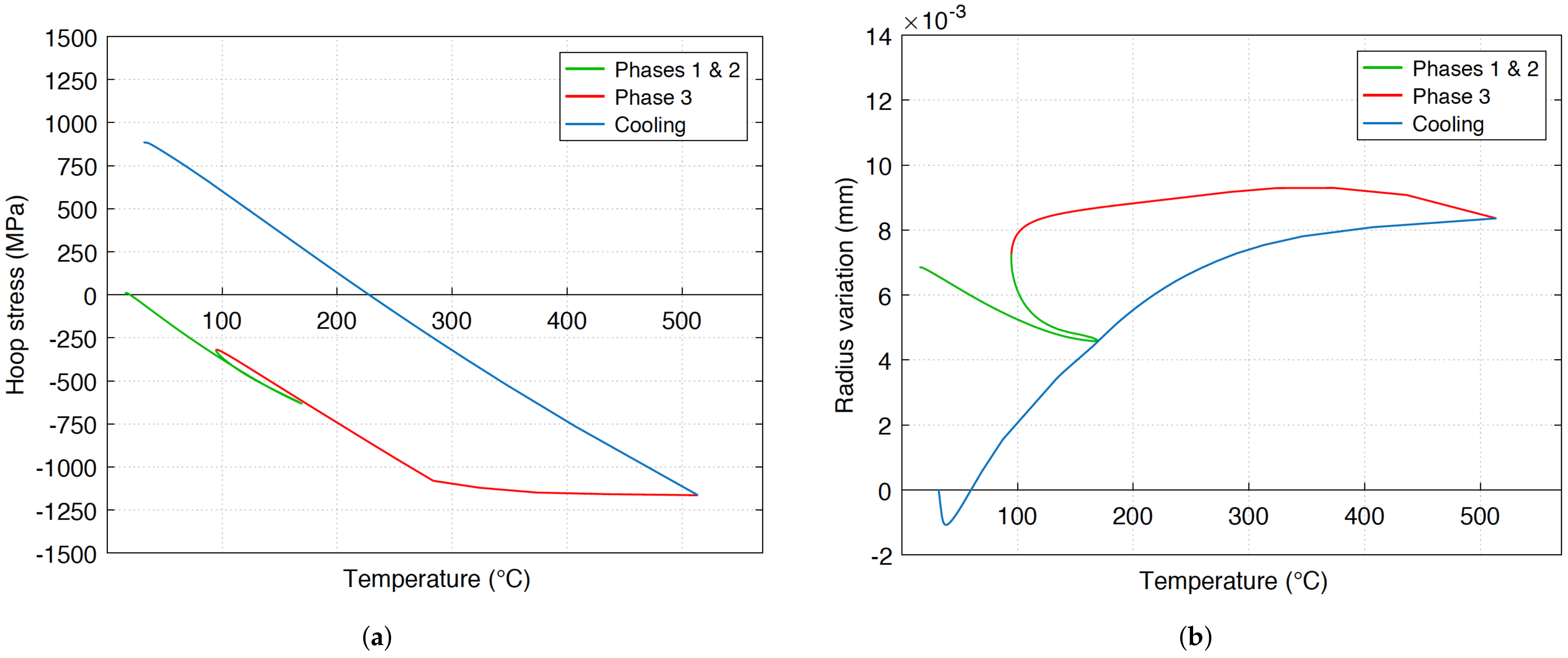
Figure 21a,b exhibit the evolution of the hoop stress and the radius variation computed during drilling at mid-depth on the hole surface. The graph of Figure 21a shows that the thermal strain field generates a compressive hoop state along the whole phases 1, 2 and 3. The beginning of plastification can be identified during phase 3 at a temperature of approximately 280 C, which is greater than the maximum ones of phases 1 and 2.
Because of this compressive hoop stress, the thermal expansion induces a hole radius larger than the one after cooling, as long as the workpiece is hot (see Figure 21b). The radius decreases all along the cooling stage in which the hoop stress sign changes and becomes positive at a temperature of approximately 225 C. It should be noted that its final intensity depends on the maximum temperature reached on the hole surface because of the linear elastic return during cooling (blue curve in Figure 21a).
4. Conclusions
The aim of this article was to analyze the impact of the thermal history upon residual stresses in the case of the dry drilling of the Inconel 718 superalloy. For this purpose, a coupled experimental and numerical approach was developed. In Section 2, both the material and the experimental methods were described. The first part of Section 3 was devoted to heat transfer:
- A thermal history in five phases was identified by means of temperature measurements with an overheating of approximately 500 C on the hole surface before the output of the drill tip;
- An improved version of a 3D thermo-viscoplastic modeling was developed to show that this overheating is triggered by the progressive decrease in the Inconel 718 volume under the cutting zone.
Such an evolution of heat transfer has never been reported and simulated before in the literature. Based on these new results, the second part of Section 3 focuses on the study of the heat transfer impact on the residual stresses generation:
- 3.
- A 3D thermo-elasto-plastic simulation including elasticity was proposed to compute the residual stresses induced by the dry drilling of a large depth hole. The loading is made of the thermal expansion due to the temperature field coming from the previous 3D thermo-viscoplastic model.
- 4.
- The comparison between experimental and simulation results shows for the first time that the thermal strain field plays a major role in residual stress generation during the dry drilling of Inconel 718.
- 5.
- The simulation also shows for the first time that the overheating stage induces plastic strains leading to high tensile residual stresses of approximately 900 MPa as we experimentally observed.
As far as lubrication is concerned, the use of lubricant prevents Inconel 718 from heating up during the whole drilling operation. On the other hand, lubrication leads to compressive residual stresses, both in the axial and hoop directions [27]. This corroborates the analysis presented in this article, which suggests that overheating in phase 3 plays a major role in residual stress generation during the dry drilling of Inconel 718.
Lubrication can have multiple impacts on heat transfer such as and calories and hot chips evacuation, modification of the mechanical dissipation at the tool–chip interface. Nevertheless, lubrication seems to be essential just before the output of the drill tip in order to avoid the generation of high tensile residual stresses on the hole surface.
Future work will focus on the optimization of lubricated conditions during the drilling operation. The main objective will be to show whether the use of lubricant can be reduced before phase 3 without producing high tensile residual stresses.
Author Contributions
Conceptualization, K.C., J.-M.B. and E.F.; methodology, K.C. and E.F.; software, K.C. and E.F.; validation, K.C. and E.F.; investigation, K.C. and D.B.; resources, M.G. and H.K.; writing—original draft preparation, K.C. and E.F.; writing—review and editing, J.-M.B. and D.B.; visualization, K.C.; supervision, J.-M.B. and E.F.; project administration, E.F.; funding acquisition, E.F. All authors have read and agreed to the published version of the manuscript.
Funding
This research received no external funding.
Institutional Review Board Statement
Not applicable.
Informed Consent Statement
Not applicable.
Data Availability Statement
Not applicable.
Acknowledgments
The authors would like to convey their gratitude to William Berckmans, Edouard Geslain and Anthony Jegat for providing the drilling experiments.
Conflicts of Interest
The authors declare no conflict of interest.
Abbreviations
The following abbreviations are used in this manuscript:
| IR | Infrared |
| TC | Thermocouple |
| XRD | X-ray diffraction |
| Thermal coefficient (W·m·C) | |
| Fourth rank elastic tensor (MPa) | |
| Elastic strain tensor (-) | |
| Elastic strain rate tensor (s) | |
| Plastic strain rate tensor (s) | |
| Thermal strain rate tensor (s) | |
| Exchange coefficient in the drilled hole (W·m·C) | |
| X-ray wavelength (nm) | |
| n | Thermal exponent (-) |
| Scan angle for the XRD analysis () | |
| q | Heat flux (W·m) |
| Cauchy stress tensor (MPa) | |
| von Mises equivalent stress (MPa) | |
| Initial yield stress (MPa) | |
| t | Time (s) |
| Temperature (C) | |
| Average temperature computed in the cutting zone (C) | |
| Temperature in the drilled hole (C) |
References
- Fauvin, F.; Roux, J.C.; Monnet, P.; Feulvarch, E. Fast estimation of the shear stress amplitude for fatigue life analysis of metals. Eur. J. Mech.-A/Solids 2020, 80, 103928. [Google Scholar] [CrossRef]
- Dang-Van, K.; Bignonnet, A.; Fayard, J.L. Assessment of welded structures by a structural multiaxial fatigue approach. Eur. Struct. Integr. Soc. 2003, 31, 3–21. [Google Scholar] [CrossRef]
- Dang-Van, K.; Griveau, B.; Message, O. On a New Multiaxial Fatigue Limit Criterion: Theory and Applications; EGF 3; Brown, M.W., Miller, K.J., Eds.; Mechanical Engineering Pulications: London, UK, 1989; pp. 479–496. [Google Scholar]
- Dudzinski, D.; Devillez, A.; Moufki, A.; Larrouquère, D.; Zerrouki, V.; Vigneau, J. A review of developments towards dry and high speed machining of Inconel 718 alloy. Int. J. Mach. Tools Manuf. 2004, 44, 439–456. [Google Scholar] [CrossRef]
- Wolf, T.; Iovkov, I.; Biermann, D. Influence of a Discontinuous Process Strategy on Microstructure and Microhardness in Drilling Inconel 718. J. Manuf. Mater. Process. 2021, 5, 43. [Google Scholar] [CrossRef]
- Sarıkaya, M.; Gupta, M.K.; Tomaz, I.; Pimenov, D.Y.; Kuntoglu, M.; Khanna, N.; Yıldırım, C.V.; Krolczyk, G.M. A state-of-the-art review on tool wear and surface integrity characteristics in machining of superalloys. CIRP J. Manuf. Sci. Technol. 2021, 35, 624–658. [Google Scholar] [CrossRef]
- Pimenov, D.Y.; Mia, M.; Gupta, M.K.; Machado, A.R.; Tomaz, I.V.; Sarikaya, M.; Wojciechowski, S.; Tadeusz, M.; Kaptonek, W. Improvement of machinability of Ti and its alloys using cooling-lubrication techniques: A review and future prospect. J. Mater. Res. Technol. 2021, 11, 719–753. [Google Scholar] [CrossRef]
- Girinon, M.; Karaouni, H.; Masciantonio, U.; Lefebvre, F.; Jourden, E.; Valiorgue, F.; Rech, J.; Feulvarch, E. Risks related to the lack of lubrication on surface integrity in drilling. Heliyon 2019, 5, e01138. [Google Scholar] [CrossRef] [Green Version]
- Sima, M.; Özel, T. Modified material constitutive models for serrated chip formation simulations and experimental validation in machining of titanium alloy Ti-6Al-4V. Int. J. Mach. Tools Manuf. 2010, 50, 943–960. [Google Scholar] [CrossRef]
- Shet, C.; Deng, X. Residual stresses and strains in orthogonal metal cutting. Int. J. Mach. Tools Manuf. 2003, 43, 573–587. [Google Scholar] [CrossRef]
- Lo, S. An analysis of cutting under different rake angles using the finite element method. J. Mater. Process. Technol. 2000, 105, 143–151. [Google Scholar] [CrossRef]
- Outeiro, J.; Umbrello, D.; M’Saoubi, R. Experimental and numerical modelling of the residual stresses induced in orthogonal cutting of AISI 316L steel. Int. J. Mach. Tools Manuf. 2006, 46, 1786–1794. [Google Scholar] [CrossRef]
- Chen, G.; Ren, C.; Yang, X.; Jin, X.; Guo, T. Finite element simulation of high-speed machining of titanium alloy (Ti-6Al-4V) based on ductile failure model. Int. J. Adv. Manuf. Technol. 2011, 56, 1027–1038. [Google Scholar] [CrossRef]
- Ozcelik, B.; Bagci, E. Experimental and numerical studies on the determination of twist drill temperature in dry drilling: A new approach. Mater. Des. 2006, 27, 920–927. [Google Scholar] [CrossRef]
- Wu, J.; Han, R. A new approach to predicting the maximum temperature in dry drilling based on a finite element model. J. Manuf. Process. 2009, 11, 19–30. [Google Scholar] [CrossRef]
- Nan, X.; Xie, L.; Zhao, W. On the application of 3D finite element modeling for small-diameter hole drilling of AISI 1045 steel. Int. J. Adv. Manuf. Technol. 2016, 84, 1927–1939. [Google Scholar] [CrossRef]
- Abouridouane, M.; Klocke, F.; Döbbeler, B. Characterisation and Modelling of the Machinability of Ferritic-pearlitic Steels in Drilling Operations. Procedia CIRP 2017, 58, 79–84. [Google Scholar] [CrossRef]
- Pang, K.; Wang, D. Study on the performances of the drilling process of nickel-based superalloy Inconel 718 with differently micro-textured drilling tools. Int. J. Mech. Sci. 2020, 180, 105658. [Google Scholar] [CrossRef]
- Bonnet, C.; Pottier, T.; Landon, Y. Development of a multi-scale and coupled cutting model for the drilling of Ti-6Al-4V. CIRP J. Manuf. Sci. Technol. 2021, 35, 526–540. [Google Scholar] [CrossRef]
- Chenegrin, K.; Roux, J.C.; Helfenstein-Didier, C.; Pouvreau, C.; Girinon, M.; Karaouni, H.; Bergheau, J.M.; Feulvarch, E. 3D numerical simulation of heat transfer during dry drilling of Inconel 718. J. Manuf. Process. 2021, 64, 1143–1152. [Google Scholar] [CrossRef]
- Girinon, M.; Valiorgue, F.; Rech, J.; Feulvarch, E. Development of a Procedure to Characterize Residual Stresses Induced by Drilling. Procedia CIRP 2016, 45, 79–82. [Google Scholar] [CrossRef] [Green Version]
- Chenegrin, K. Identification et Modélisation des Phénomènes Thermomécaniques mis en jeu lors du Perçage à sec de L’Inconel 718. Ph.D. Thesis, Université de Lyon, Lyon, France, 2021. [Google Scholar]
- Zemzemi, F. Caracterisation de Modèles de Frottement aux Interfaces Pièce-Outil-Copeau en Usinage: Application au cas de L’usinage des Aciers et de L’Inconel 718. Ph.D. Thesis, École Centrale de Lyon, Écully, France, 2007. [Google Scholar]
- Software SYSWELD®. Reference Manual; ESI Group: Lyon, France, 2020. [Google Scholar]
- Feulvarch, E.; Lacroix, R.; Deschanels, H. A 3D locking-free XFEM formulation for the von Mises elasto-plastic analysis of cracks. Comput. Methods Appl. Mech. Eng. 2020, 361, 112805. [Google Scholar] [CrossRef]
- Wang, H.; Webb, T.; Bitler, J. Study of thermal expansion and thermal conductivity of cemented WC-Co composite. Int. J. Refract. Met. Hard Mater. 2015, 49, 170–177. [Google Scholar] [CrossRef]
- Girinon, M.; Dumont, F.; Valiorgue, F.; Rech, J.; Feulvarch, E.; Lefebvre, F.; Karaouni, H.; Jourden, E. Influence of lubrication modes on residual stresses generation in drilling of 316L, 15-5PH and Inconel 718 alloys. Procedia CIRP 2018, 71, 41–46. [Google Scholar] [CrossRef]
Figure 1.
Geometry of experimental tests: (a) drilled workpiece; and (b) drill tool.

Figure 2.
Heat treatment for annihilating initial residual stresses before drilling.
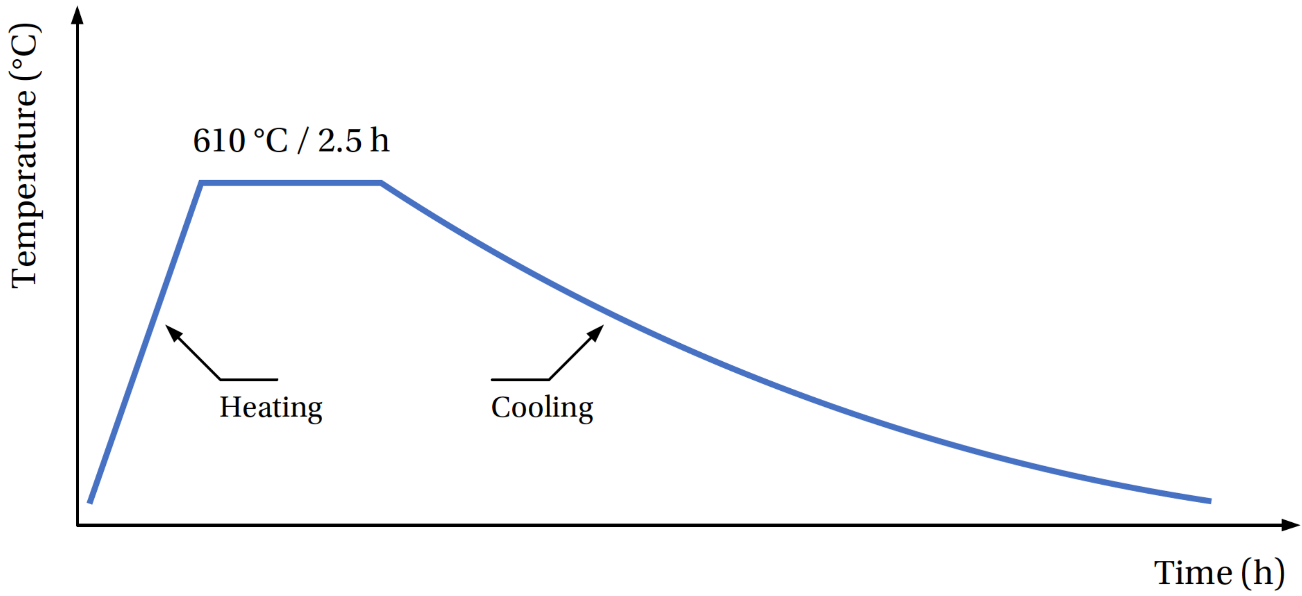
Figure 3.
Experimental setup during the dry drilling tests.

Figure 4.
Position of the thermocouples: (a) radial positions; and (b) depth positions.

Figure 5.
Cutting procedure: (a) cutting zones; and (b) sample used for XRD analysis.

Figure 6.
Characteristics of the XRD analysis: (a) analysis points; and (b) analysis directions.
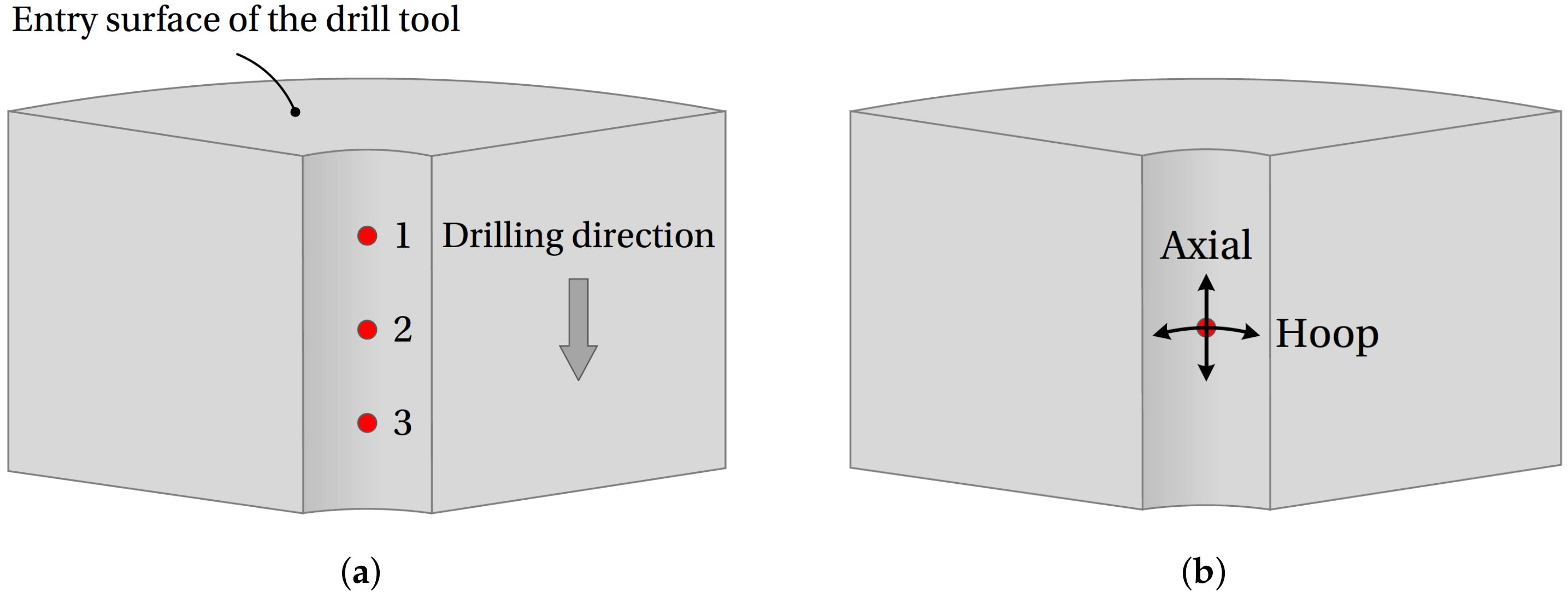
Figure 7.
Elasto-plastic properties of the Inconel 718 superalloy: (a) Young’s modulus [22]; and (b) plastic strain–stress curves [23].
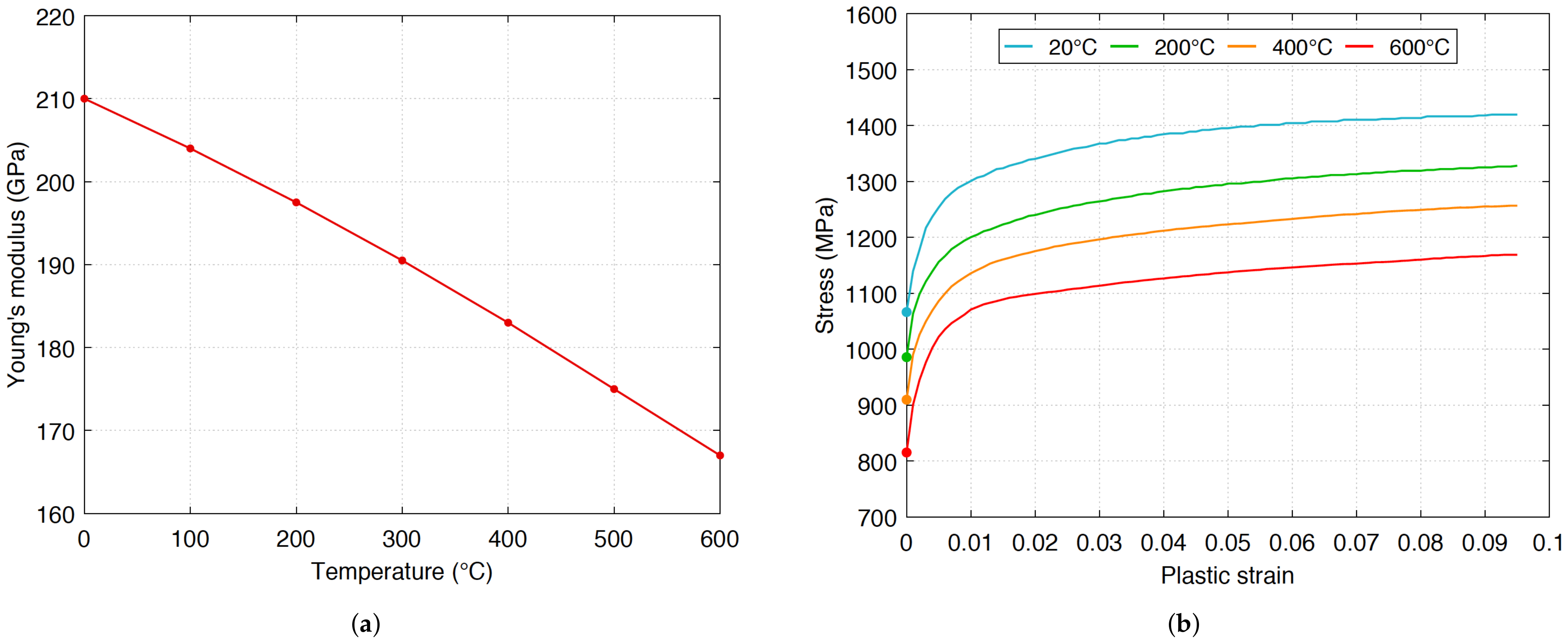
Figure 8.
Temperature measurements for the 3 drilling tests: (a) Test n1; (b) Test n2; and (c) Test n3.
Figure 8.
Temperature measurements for the 3 drilling tests: (a) Test n1; (b) Test n2; and (c) Test n3.
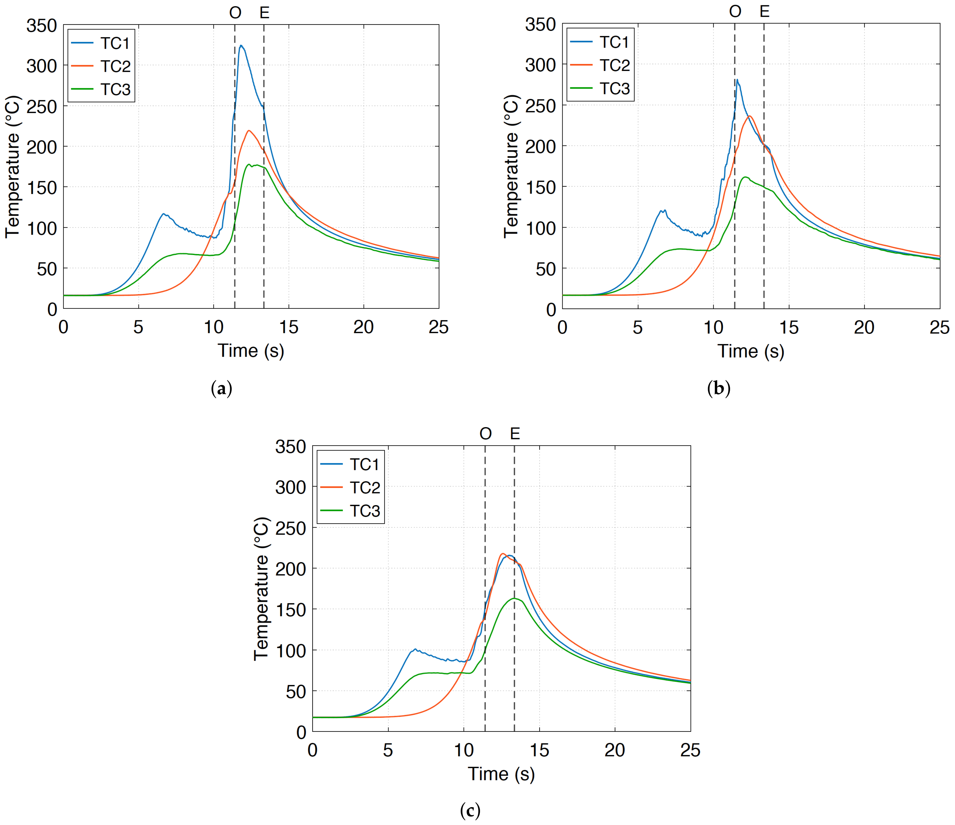
Figure 9.
Pictures from the IR camera: (a) during the dry drilling; and (b) after the upward ejection of the tool.
Figure 9.
Pictures from the IR camera: (a) during the dry drilling; and (b) after the upward ejection of the tool.
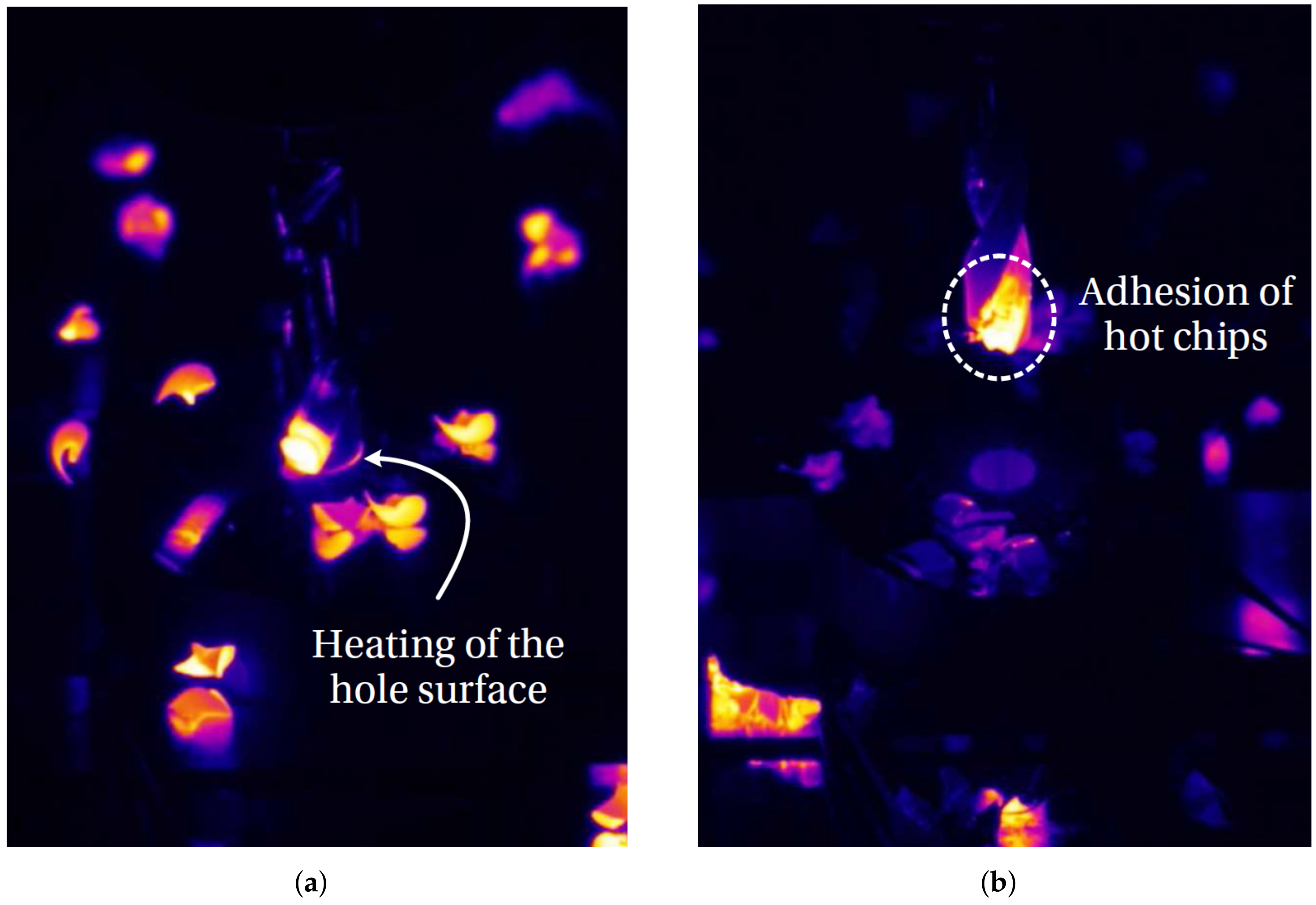
Figure 10.
Thermal history of Inconel 718 on the dry drilled hole surface.
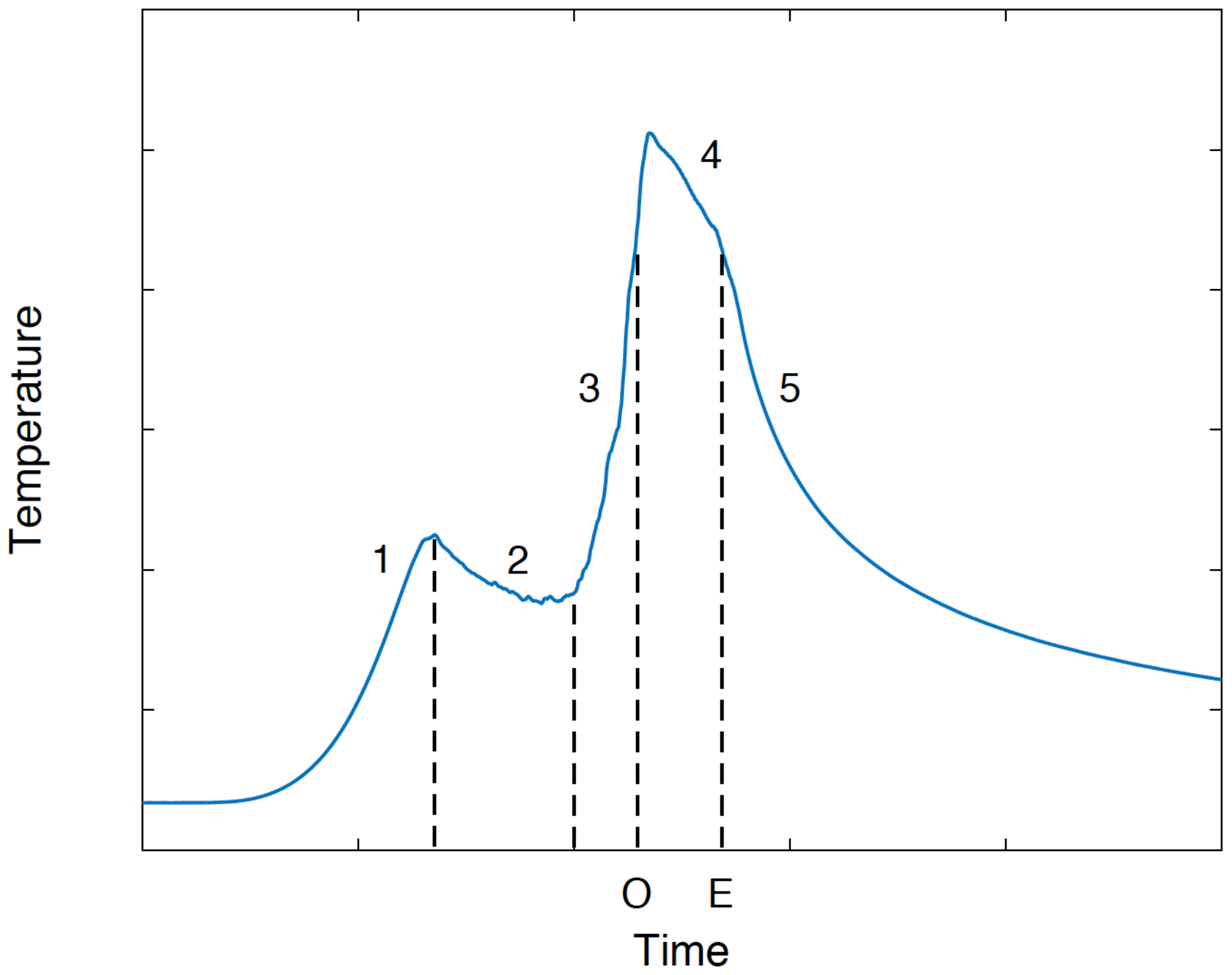
Figure 11.
Overheating of the cutting zone just before the end of the drilling operation.
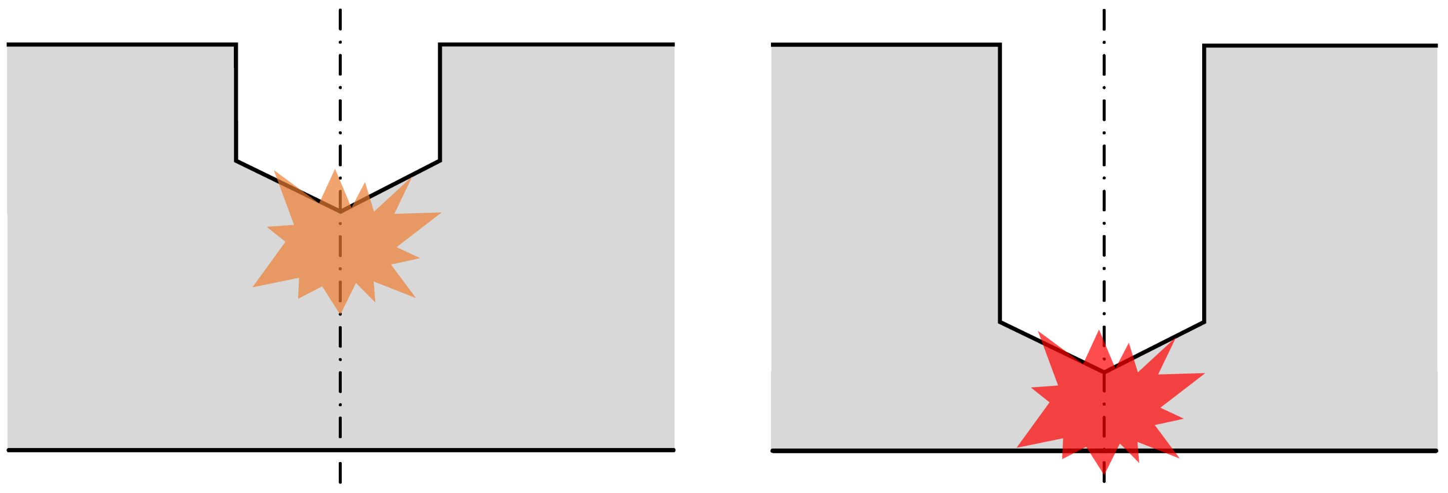
Figure 12.
Average temperature in the cutting zone: (a) cutting zone’s mesh in purple; and (b) time evolution.
Figure 12.
Average temperature in the cutting zone: (a) cutting zone’s mesh in purple; and (b) time evolution.
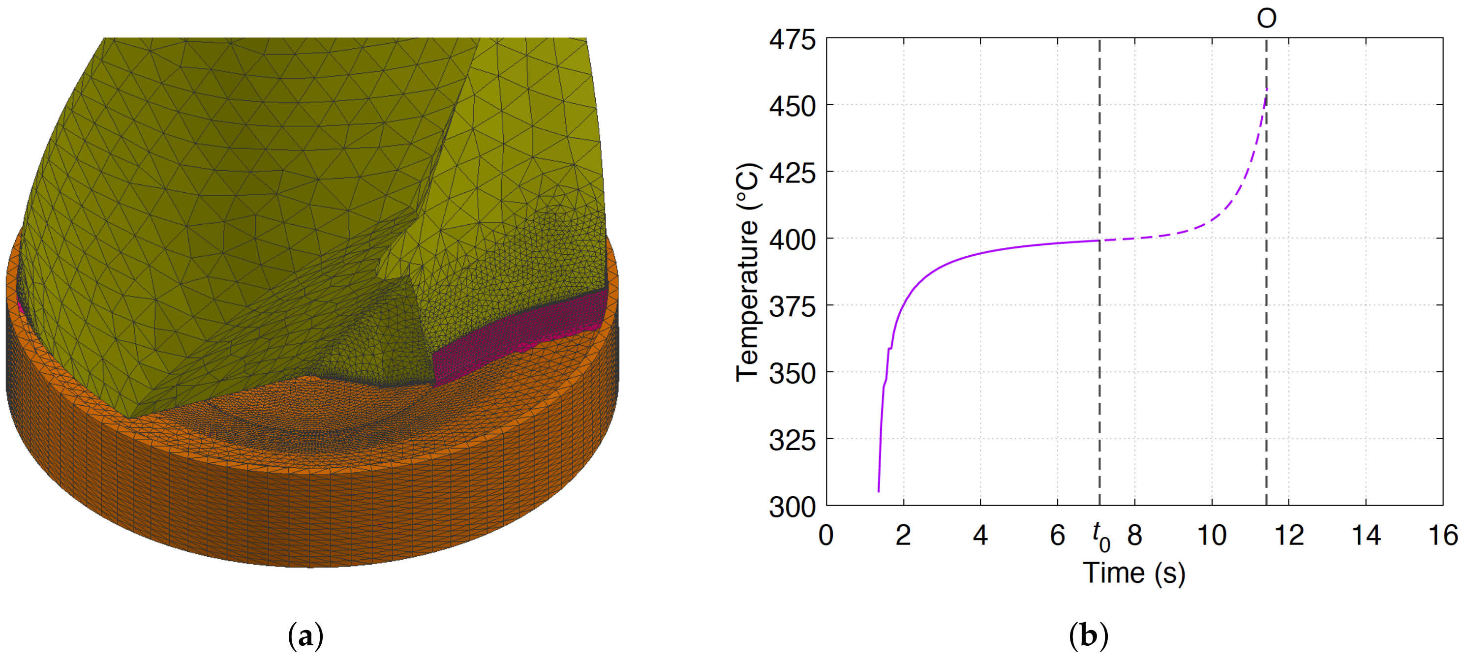
Figure 13.
Comparison between experimental test n1 and the improved numerical model.
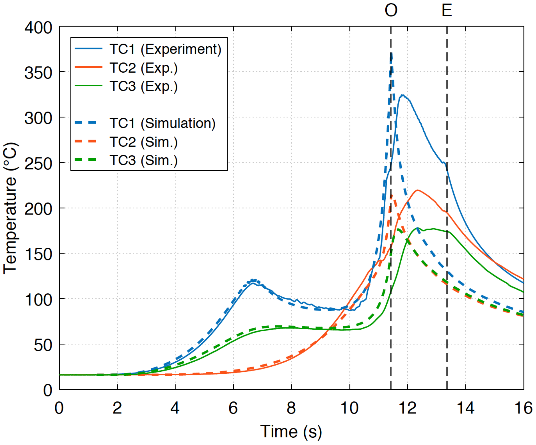
Figure 14.
Temperature evolution (C) simulated during the dry drilling operation: (a) phase 1 ( s); (b) phase 2 ( s); and (c) phase 3 (time “O”).
Figure 14.
Temperature evolution (C) simulated during the dry drilling operation: (a) phase 1 ( s); (b) phase 2 ( s); and (c) phase 3 (time “O”).
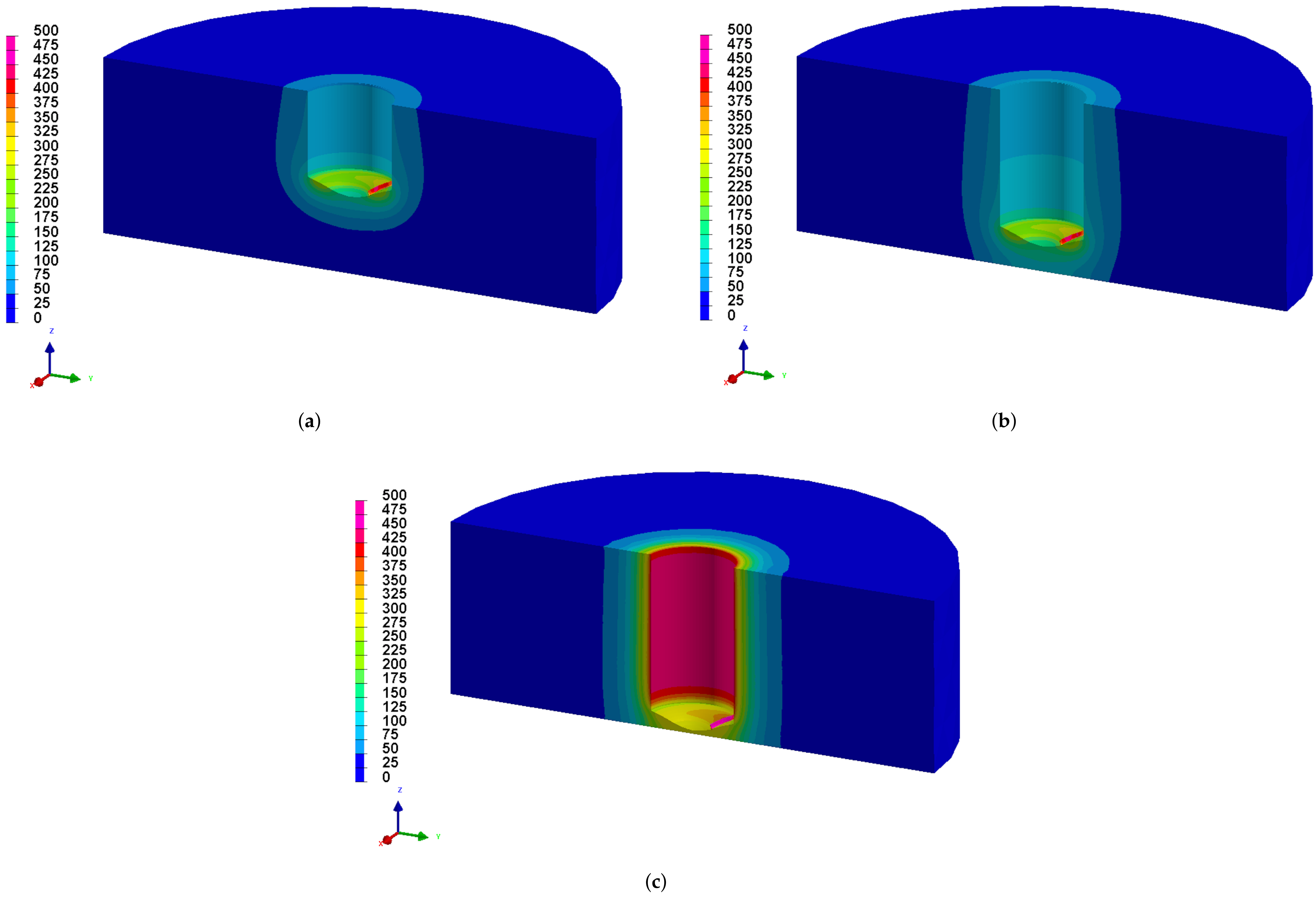
Figure 15.
Mesh of the 3D thermo-elasto-plastic modeling.

Figure 16.
Distribution of temperature (C) after projection.

Figure 17.
Distribution of experimental diameter after dry drilling.
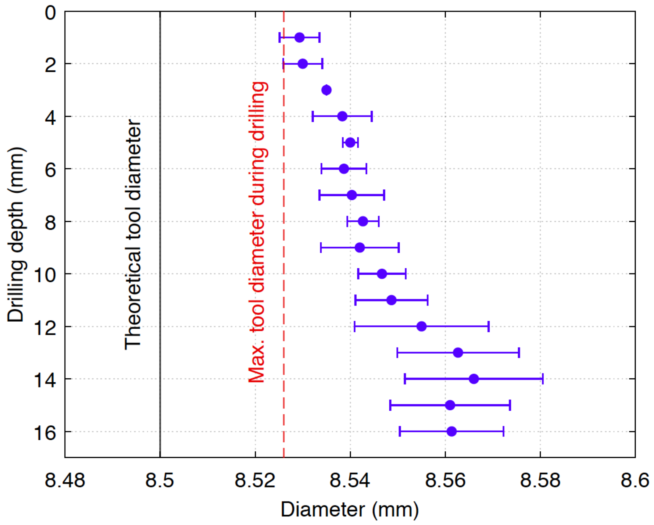
Figure 18.
Distribution of hoop residual stresses (MPa).
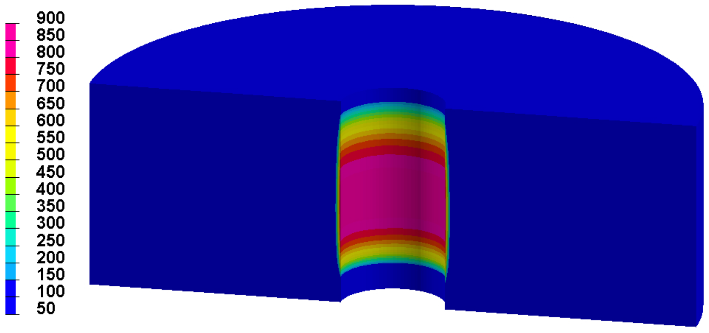
Figure 19.
Comparison between experimental and numerical results: (a) axial residual stress; and (b) hoop residual stress.
Figure 19.
Comparison between experimental and numerical results: (a) axial residual stress; and (b) hoop residual stress.
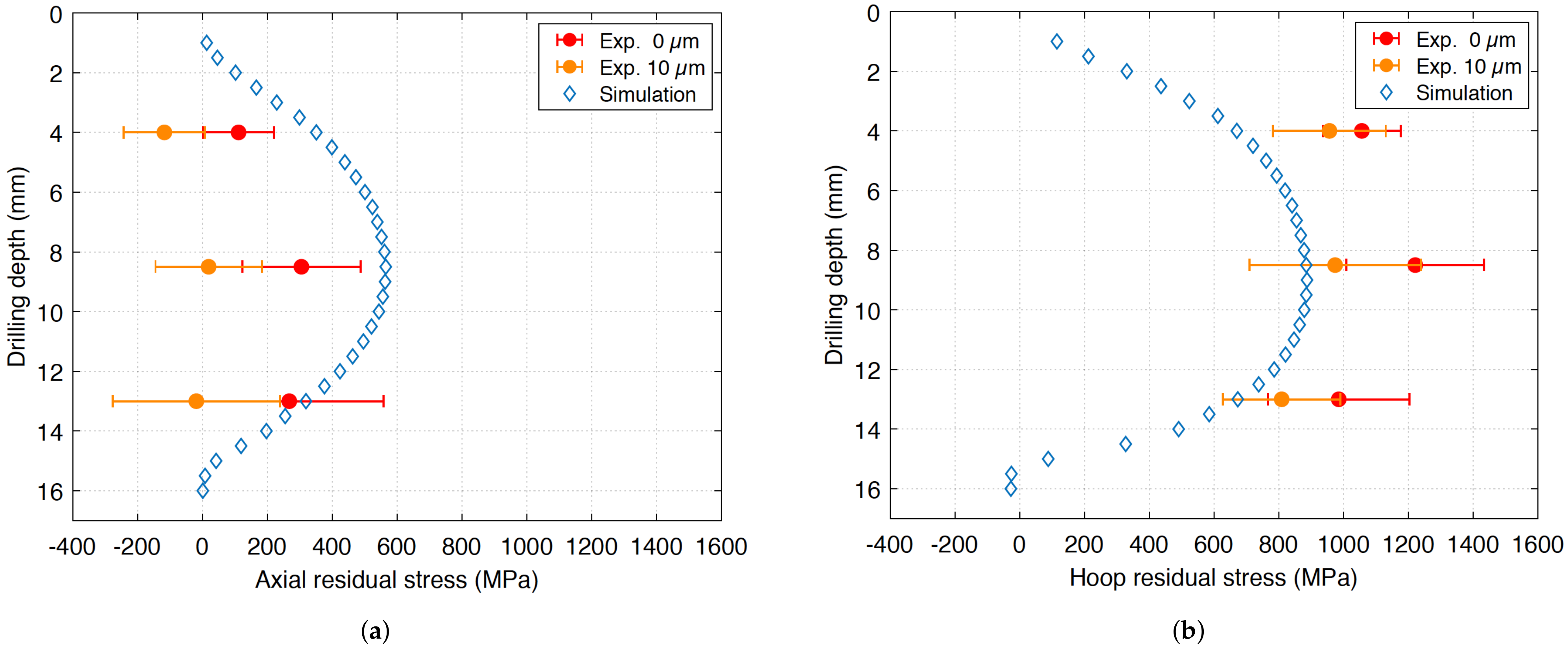
Figure 20.
Numerical detection of the beginning of plasticity.
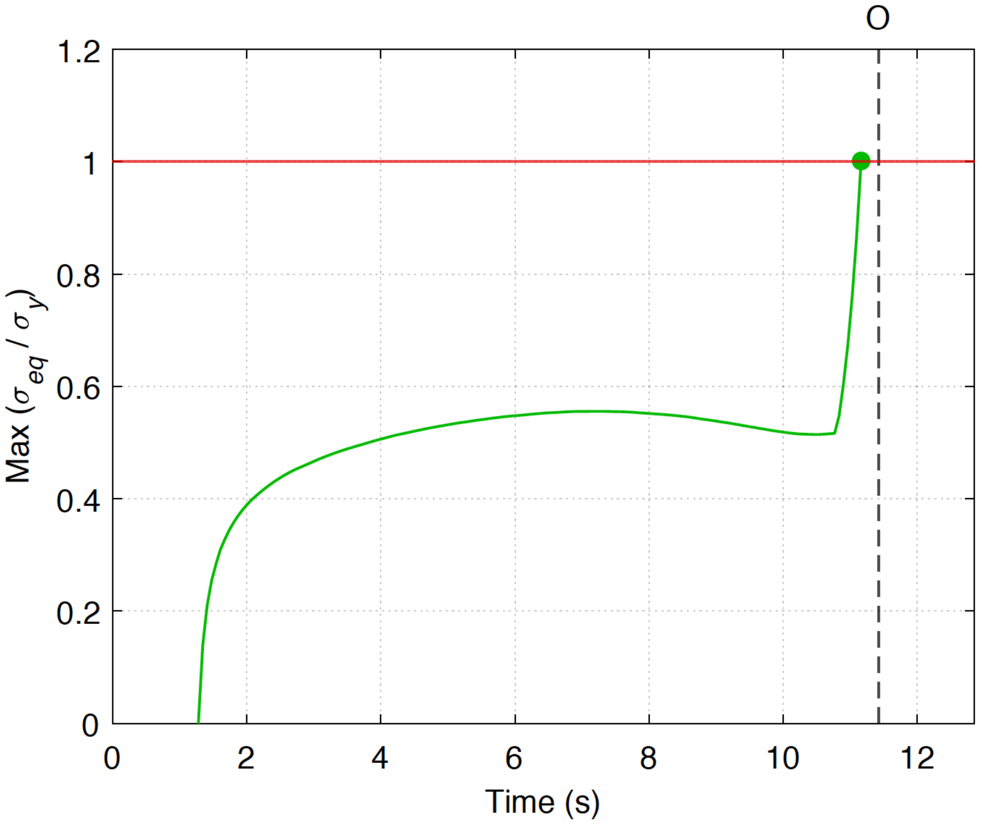
Figure 21.
Mechanical history of the hole surface simulated during the dry drilling at mid-depth: (a) hoop stress evolution; and (b) radius variation in reference to the final radius.
Figure 21.
Mechanical history of the hole surface simulated during the dry drilling at mid-depth: (a) hoop stress evolution; and (b) radius variation in reference to the final radius.

Table 1.
Chemical composition of Inconel 718 superalloy (in wt%).
| Ni | Cr | Fe | Nb | Mo | Ti | Al |
|---|---|---|---|---|---|---|
| 50–55 | 17–21 | 15–21 | 4.75–5.5 | 2.8–3.3 | 0.65–1.15 | 0.2–0.8 |
Table 2.
Analysis distance from the entry surface of the drill tool.
| Analysis Point | 1 | 2 | 3 |
|---|---|---|---|
| Distance | 4 mm | 8.5 mm | 13 mm |
Publisher’s Note: MDPI stays neutral with regard to jurisdictional claims in published maps and institutional affiliations. |
© 2022 by the authors. Licensee MDPI, Basel, Switzerland. This article is an open access article distributed under the terms and conditions of the Creative Commons Attribution (CC BY) license (https://creativecommons.org/licenses/by/4.0/).
Share and Cite
MDPI and ACS Style
Chenegrin, K.; Bouscaud, D.; Girinon, M.; Karaouni, H.; Bergheau, J.-M.; Feulvarch, E. Study of the Thermal History upon Residual Stresses during the Dry Drilling of Inconel 718. Metals 2022, 12, 305. https://doi.org/10.3390/met12020305
AMA Style
Chenegrin K, Bouscaud D, Girinon M, Karaouni H, Bergheau J-M, Feulvarch E. Study of the Thermal History upon Residual Stresses during the Dry Drilling of Inconel 718. Metals. 2022; 12(2):305. https://doi.org/10.3390/met12020305
Chicago/Turabian StyleChenegrin, Kévin, Denis Bouscaud, Mathieu Girinon, Habib Karaouni, Jean-Michel Bergheau, and Eric Feulvarch. 2022. "Study of the Thermal History upon Residual Stresses during the Dry Drilling of Inconel 718" Metals 12, no. 2: 305. https://doi.org/10.3390/met12020305
Note that from the first issue of 2016, this journal uses article numbers instead of page numbers. See further details here.