
Metallic Glassy Hollow Microfibers


Institute of Materials, School of Materials Science and Engineering, Shanghai University, Shanghai 200444, China
*
Author to whom correspondence should be addressed.
Metals 2022, 12(9), 1463; https://doi.org/10.3390/met12091463
Submission received: 19 July 2022
/
Revised: 28 August 2022
/
Accepted: 29 August 2022
/
Published: 31 August 2022
(This article belongs to the Special Issue Development and Application of Microscale Metallic Fibers)
Abstract
:Hollow microfibers can be fabricated by using different materials such as metals and glass. The inner diameter of strong, tough, and conductive metallic tubes is on a submillimeter scale while that of quartz glass tubes made by thermoplastic forming can reach 5 nm. However, quartz glass tubes are brittle and nonconductive. Metallic glasses (MGs) are strong, tough, conductive, and have a thermoplastic forming ability. Theoretically, such materials can be used to produce strong, tough, and conductive hollow microfibers. Here, we report a method to fabricate MG hollow microfibers via thermoplastic forming bulk Pd43Cu27Ni10P20 MG tubes in their supercooled-liquid region. Uniform and smooth MG hollow microfibers with single and multiple channels were successfully fabricated by this method. Investigation of the heterogeneous microstructure of the fibers revealed their forming mechanism. The hollow microfibers might attract scientific interest and may have engineering applications in areas such as electrochemistry, microelectromechanical devices, medicine, and biology.
1. Introduction
Hollow microfibers (HMs) have generated a significant amount of attention due to their low density, large specific surface area, high-loading capacity, and widespread potential applications in areas such as optical, electric, magnetic sensor, and biomedical engineering [1,2,3,4,5]. However, the performance and potential applications of HMs are strongly affected by the properties of their material [6]. For metals, such as copper and stainless steel, their HMs generally have high toughness and conductivity due to crystal defects such as dislocations [7,8]. Whereas, glasses without crystal defects are more accessible for fabricating HMs. For example, quartz glass with a high thermoplastic forming ability is commonly used for preparing HMs, which can reach a diameter of 5 nm [9,10]. The fatal weakness of quartz glass HMs is their brittleness and nonconductivity. In order to circumvent the shortcomings, a novel amorphous material (metallic glasses (MGs)) is taken as a candidate material for preparing the HMs with high performance. MG HMs would extend the function and application of engineering HMs and MGs.
MGs possess the characteristics of metals and glasses described above and remain an extensive attraction in materials science and condensed matter physics after the discovery of Au75Si25 MG in 1960 [11]. Due to their disordered microstructure and absence of dislocations, MGs possess superior mechanical properties [12,13,14] and excellent physical and chemical properties [15,16,17]. In particular, as with traditional glasses, MGs also have glass transitions [18] in their supercooled-liquid region. Glass transition behavior of metallic glasses can be described by using Angel’s plot and the Vogel–Tammann–Fulcher equation [19]. Additionally, the superplastic deformation behavior of MGs in their supercooled-liquid region has also been reported [20,21].
Furthermore, MGs have a unique thermoplastic forming ability in their supercooled-liquid region, which make MGs able to be stretched, compressed, and formed into complicated shapes and used as potential materials for micromanufacturing [15,22,23]. Many microscale MG structures, such as thin film [24], wires [25,26], and other structures [27], have been successfully fabricated and have high potential in different applications. For instance, metallic glass fibers were used as electrical resistance strain gauges [28] and micro-fuel cells for portable electronics applications [29]. However, there are few reports about metallic glass HMs. In particular, the metallic glass nanotube array was fabricated by using a nanomoulding technique [30]. However, the nanotubes were short and susceptible to oxidization. In addition, nanotubes with multiple channels could not be fabricated using this technique.
Here, we develop a thermoplastic forming technique for the fabrication of metallic glass HMs via thermoplastic deformation of bulk MG tubes in a vacuum chamber with a computer program to precisely control the heating process. The continuous metallic glass HMs have a smooth surface, a high-aspect ratio, and multiple channels. In addition, the 3D microstructure of the HMs was reconstructed by using synchrotron X-ray nano-CT and it demonstrated the forming mechanism of the HMs.
2. Materials and Methods
2.1. Preparation of Bulk MG Tubes
The master alloy ingots with the composition of Pd43Cu27Ni10P20 were prepared by arc melting (Physience Opto-electronics Co., Ltd., Beijing, China) a mixture of Pd43Cu27Ni10 alloy ingot, induction heating the ingot with pure (99.999 wt.%) P grains with a weight 15% higher than its calculated value, and subsequent fluxing of the Pd-Cu-Ni-P ingot with the Pd43Cu27Ni10 ingot (with calculated weight) and B2O3 in a vacuum sealed quartz tube. We made Pd40Ni10Cu30P20 bulk MG rods with a diameter of 1 mm and a 2 mm head, as shown in Figure 1a, by using a copper-mold-casting method in a vacuum chamber under argon atmosphere, and these rods were sliced to a length of 10 mm by using a diamond wafering blade (Shenyang KEJING, Shenyang, China). Bulk MG tubes with single and multiple holes were prepared by drilling the end of the MG rod using a desktop drill press with WC drills (Shenyang KEJING, Shenyang, China) (Φ 0.5 mm × 7 mm for single channel HMs, Φ 0.4 mm × 5 mm for double channel HMs, and Φ 0.3 mm × 4 mm for triple channel HMs). The drill could be easily broken because the chips that formed during drilling induced strong friction, which made continuous drilling inappropriate. Thus, the drill needed to be lifted out of the hole once a second to remove the chips and frictional heat. This action could also remove frictional heating to avoid crystallization. In addition, an XY manual positioning stage was used to position the MG rods to drill the hole at the expected positions.
2.2. Electrodeposition of Cu
Because the depth of the holes drilled in the rods was limited, Cu was electrodeposited onto the solid part of the bulk MG where thermoforming was not expected to happen. The electrodeposition solution that we used was composed of sulfuric acid (98 wt.%), cupric sulfate pentahydrate, and deionized water, and the concentration of H2SO4 and CuSO4 in the electrolyte were 0.75 mol/L and 1 mol/L, respectively. Copper-phosphorous plates (20 mm × 5 mm × 2 mm) (B-59-P08, Yamamoto-MS Co., Ltd., Tokyo, Japan) were used as the anode and the bulk of the MG tubes were used as the cathode. A constant current was provided by a power supply (Keithley 2230G-30-1, Keithley, Cleveland, OH, USA) with an initial current density of 0.1 mA/mm2. The thickness of the copper coating (50 μm) was precisely controlled by the electrodeposition time. The details of the calculation of the electrodeposition time can be found in the literature [31]. In addition, a magnetic stirrer was used for stirring the solution during electrodeposition.
2.3. Morphology and Microstructure Characterization
The cross-sections of the single channel samples were prepared by using an IM4000 Hitachi Ion Milling System (Hitachi, Tokyo, Japan), while those of the HMs with multiple channels were prepared by cutting them into short tubes, embedding them into resin, and subsequent polishing using SiC paper. The resin was then dissolved in acetone. The cross-section morphology of MG HMs was investigated by using HITACHI SU-1500 (Hitachi, Tokyo, Japan) scanning electron microscopy (SEM). The fully amorphous structure of the as-drawn MG HMs was confirmed by using X-ray diffraction (XRD) (Rigaku, Tokyo, Japan) and a JEM-2010F (JEOL, Tokyo, Japan) transmission electron microscope (TEM). The TEM samples with dimensions of 3.1 µm × 2.3 µm × 100 nm were prepared by using a 600i focused ion beam (FIB) (FEI, San Antonio, TX, USA). The 3D microstructure of the single channel MG HMs was detected and reconstructed by using the synchrotron X-ray nano-CT (Beijing Electron Positron Collider, Beijing, China) at the 4W1A beamline of the Beijing Synchrotron Radiation Facility (BSRF) [32]. The outer diameter of the nano-CT samples was less than 10 μm. Avizo software version 8.0 (Thermo Fisher Scientific, New York, NY, USA) was used to analyze the gray value to reconstruct the microstructure of the MG HMs. In addition, the explanation of the g values can be found in the literature [33].
3. Results and Discussion
3.1. Preparing Preform for MG HMs
Bulk MG tubes as the preform are crucial for the preparation of MG HMs. Bulk Pd43Cu27Ni10P20 MG tubes were prepared by using WC drills. The MG tube with a single hole (Φ 0.5 mm × 7 mm) is shown in Figure 1a, and the part below (Φ 2 mm × 2 mm) was for clamping during drawing. The hole was in the center of the rod for uniform thermoplastic forming of the bulk MG tubes in their supercooled-liquid region. The Cu was then electrodeposited onto the solid part of the bulk MG tubes, as shown in Figure 1b. Figure 1c shows that a Cu wire was inserted into the hole of a bulk MG tube with a depth of 0.5 mm for drawing during thermoplastic forming. The preparation of bulk MG tubes with multiple holes is similar and not presented here.
3.2. The Instrumentation for Fabricating MG HMs
The instrumentation for the thermoplastic forming of MG HMs is shown in Figure 2. The heating device was a tungsten filament (taken from Osram 64460U halogen lamp (Osram, Berlin, German)) which was inserted into a ceramic holder used for insulating electric currents and reserve heat, as shown in Figure 2a. Figure 2b shows the whole instrumentation which was fixed in a vacuum chamber through a threaded rod at the top. The tungsten filament was fixed using two copper screws which were connected to copper wires to provide an electric current. The copper wire was connected to a programmable Agilent E3642A power supply (Agilent, Cleveland, OH, USA) outside of the vacuum chamber through multi-pin power feedthrough. The preform was fixed onto the instrument by a stainless-steel screw, as shown in Figure 2b. The thermoplastic-forming drawing force was provided by a stainless-steel cylinder with a weight of 20 g, and the cylinder connected the bulk MG tubes through the Cu wire, as mentioned in Section 3.1.
However, because the tungsten filament could be heated to over 2000 °C in less than 1 s, the heating rate was so fast that the temperature of the MG tube could not be controlled precisely manually. In addition, the viscosity of the MG supercooled liquids is very sensitive to both temperature and time [34]. Therefore, a LabVIEW (LabVIEW 2016, New York, NY, USA) program (see the Supplementary File) was used to precisely control the heating current and time. The heating process and working interface of the LabVIEW program are shown in Figure 2c,d.
3.3. Fabrication of MG HMs
As shown in Figure 2d, the maximum voltage was set as 8 V. When the pure Ar atmosphere in the vacuum chamber was prepared, heating of the MG tube was started with a current of I1. While the thermoplastic drawing of the MG tube started (at t1 as shown in Figure 2c), the first stop button was pressed to switch the current to I2 which was set to 2.8 A to keep the supercooled liquid warm. In addition, the duration of I1 (t1 in Figure 2c) was recorded at the press of the first stop button. When the drawing was done, the second stop button was hit to end the program. The timeout for I1 was set as 180 s because a heating time longer than that would have induced crystallization of the MG tube. Additionally, the timeout for I2 was set as 120 s because a warming time longer than that would have induced crystallization of the drawn fiber.
In the preparation process, the relationship between I1 and heating duration (t) was investigated, as shown in Figure 3 which demonstrates that t decreased rapidly with increasing I1. According to Joule’s law, conduction current converts electrical energy into heat, and the larger the I1, the higher heat, and the faster the supercooled-liquid region is reached for thermoplastic forming of the bulk MG tubes.
3.4. Morphology of the MG HMs
Figure 4a presents an optical image of an as-drawn Pd43Cu27Ni10P20 MG tube. The length of the samples was more than 20 cm. The inner diameter of the microtubes with a single hole was drawn down to 5.5 µm, and the thickness of the wall was about 4µm (as shown in Figure 4b). It is worth noting that the channel was a perfect circle without distortion, and the inner surface was smooth. Moreover, we also successfully prepared the Pd43Cu27Ni10P20 MG HMs with multiple channels. The SEM image of double and triple channel MG HMs are shown in Figure 4c,d. It is obvious that the channels were distorted, we think that the bulk tubes with multiple holes were subjected to an uneven temperature field or drawing stress during thermoplastic deformation. However, the cross-sections of the HMs were as homogeneous as the solid fibers in our previous work [25] and previous literature [30,35]. The microstructure of the MG HMs was examined by using TEM. The selected area electron diffraction pattern and high-resolution TEM image indicate that the fibers are fully amorphous.
3.5. Heterogeneous Microstructure of the MG HMs
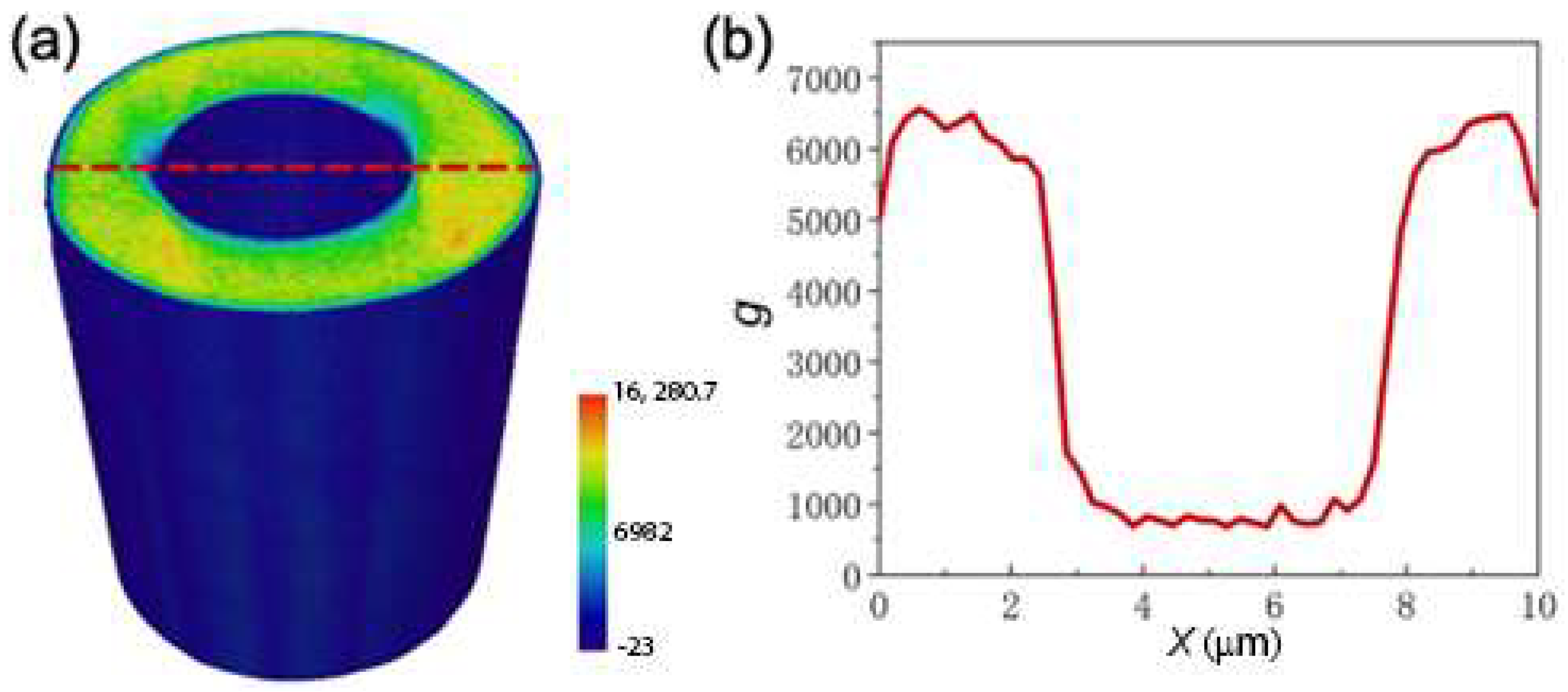
The theory of thermoplastic forming states that the surface layer of the HMs flows faster than the inner layers. Moreover, the thermoplastic flow of metallic glass is a process in which the generation and diffusion annihilation of free volume are counterbalanced [36]. When the velocity of layer flow is large, the free volume does not have enough time to annihilate, increasing free volume. Therefore, the density fluctuation is incurred due to the velocity gradient in the radial direction. For the MG HMs, a radial density gradient can be observed as shown by the nano-CT g image in Figure 5a, which shows that the density at the inner and outer surfaces are lower than the inner part while other literature [37] has not reported the heterogeneity of MG fibers fabricated by the thermoplastic drawing method. The radial line scan results for the HM of g versus the distance (x) from the left end of the dashed line in Figure 5a is shown in Figure 5b, further indicate the density gradient. Therefore, the forming mechanism of the MG HMs is that they are formed through layer-by-layer extraction of supercooled liquid by surface tension from the Master MG tube. Therefore, we believe that the thermoplastic forming here was not superplastic deformation as depicted in previous literature [30,35].
4. Conclusions
In summary, we successfully fabricated the continuous and fully amorphous Pd43Cu27Ni10P20 metallic glass hollow microfibers with single and multiple channels by drawing bulk metallic glass tubes in their supercooled-liquid region via thermoplastic drawing and precisely controlled the fabrication through a computer program. The density heterogeneity of the metallic MG HMs was observed in a 3D reconstructed nano-CT g image. The density fluctuation demonstrates that the formation of the HMs was a layer-by-layer material extraction process and not superplastic deformation. Our results introduced a new member to hollow microfibers and could put metallic glasses into new engineering applications, as well as help to understand the thermoplastic forming of metallic glasses.
Supplementary Materials
The following supporting information can be downloaded at: https://www.mdpi.com/article/10.3390/met12091463/s1.
Author Contributions
Conceptualization, J.Y.; methodology, J.Z. and J.Y.; validation, J.Z., B.H., G.W. and J.Y.; formal analysis, J.Z., G.W. and J.Y.; investigation, J.Z.; resources, J.Y., B.H. and G.W.; data curation, J.Z.; writing—original draft preparation, J.Z.; writing—review and editing, J.Z. and J.Y.; visualization, J.Z.; supervision, J.Y.; project administration, J.Y.; funding acquisition, J.Y. All authors have read and agreed to the published version of the manuscript.
Funding
This research was funded by the National Science Foundation of China (Nos. 51827801, 52171160, and 51901122) and the Beijing Electron Positron Collider (BEPC) project (No. 2020-BEPC-PT-004661).
Institutional Review Board Statement
Not applicable.
Informed Consent Statement
Not applicable.
Data Availability Statement
Not applicable.
Acknowledgments
The authors would like to thank Xue Liang for assistance in FIB and Pengfei Hu for assistance in TEM.
Conflicts of Interest
The authors declare no conflict of interest that could have appeared to influence the work reported in this paper.
References
- Baughman, R.H. Carbon nanotube actuators. Science 1999, 284, 1340–1344. [Google Scholar] [CrossRef] [PubMed]
- Solovev, A.A.; Mei, Y.; Bermudez Urena, E.; Huang, G.; Schmidt, O.G. Catalytic microtubular jet engines self-propelled by accumulated gas bubbles. Small 2009, 5, 1688–1692. [Google Scholar] [CrossRef] [PubMed]
- Zhou, L.; Zhuang, Z.; Zhao, H.; Lin, M.; Zhao, D.; Mai, L. Intricate hollow structures: Controlled synthesis and applications in energy storage and conversion. Adv. Mater. 2017, 29, 1602914. [Google Scholar] [CrossRef]
- Xu, B. Tubular micro/nanomachines: From the basics to recent advances. Adv. Funct. 2017, 28, 1705872. [Google Scholar] [CrossRef]
- Miranda, C.; Sampath Kumar, S.; Muthuswamy, J.; Smith, B.S. Photoacoustic micropipette. Appl. Phys. Lett. 2018, 113, 264103. [Google Scholar] [CrossRef]
- Singhal, R.; Bhattacharyya, S.; Orynbayeva, Z.; Vitol, E.; Friedman, G.; Gogotsi, Y. Small diameter carbon nanopipettes. Nanotechnology 2010, 21, 015304. [Google Scholar] [CrossRef]
- Zhang, S.; Mielke, S.L.; Khare, R.; Troya, D.; Ruoff, R.S.; Schatz, G.C.; Belytschko, T. Mechanics of defects in carbon nanotubes: Atomistic and multiscale simulations. Phys. Rev. B 2005, 71, 115403. [Google Scholar] [CrossRef]
- Wang, G.; Li, X. Predicting young’s modulus of nanowires from first-principles calculations on their surface and bulk materials. J. Appl. Phy. 2008, 104, 113517. [Google Scholar] [CrossRef]
- Tamizhanban, R.; Sreejith, K.R.; Jayanth, G.R. An automated pipette puller for fabrication of glass micropipettes. Rev. Sci. Instrum. 2014, 85, 055105. [Google Scholar] [CrossRef]
- Klony Lieberman, A.L. Multifunctional, micropipette based force cantilevers for scanned probe microscopy. Rev. Sci. Instrum. 2014, 85, 055105. [Google Scholar] [CrossRef]
- Jun, W.K.; Duwez, P.O.L. Non-crystalline structure in solidified gold–silicon alloys. Nature 1960, 187, 869–870. [Google Scholar]
- Greer, A.L. Metallic glasses... On the threshold. Mater. Today 2009, 12, 14–22. [Google Scholar] [CrossRef]
- Demetriou, M.D.; Launey, M.E.; Garrett, G.; Schramm, J.P.; Hofmann, D.C.; Johnson, W.L.; Ritchie, R.O. A damage-tolerant glass. Nat. Mater. 2011, 10, 123–128. [Google Scholar] [CrossRef] [PubMed]
- Schuh, C.; Hufnagel, T.; Ramamurty, U. Mechanical behavior of amorphous alloys. Acta Mater. 2007, 55, 4067–4109. [Google Scholar] [CrossRef]
- Wang, W.H. Bulk metallic glasses with functional physical properties. Adv. Mater. 2009, 21, 4524–4544. [Google Scholar] [CrossRef]
- Hu, Y.C.; Wang, Y.Z.; Su, R.; Cao, C.R.; Li, F.; Sun, C.W.; Yang, Y.; Guan, P.F.; Ding, D.W.; Wang, Z.L.; et al. A highly efficient and self-stabilizing metallic-glass catalyst for electrochemical hydrogen generation. Adv. Mater. 2016, 28, 10293–10297. [Google Scholar] [CrossRef]
- Wang, Y.T.; Bai, H.Y.; Pan, M.X.; Zhao, D.Q.; Wang, W.H. Multiple spin-glass-like behaviors in a Pr-based bulk metallic glass. Phys. Rev. B 2006, 74, 064422. [Google Scholar] [CrossRef]
- Chen, H.S.; Turnbull, D. Evidence of a glass–liquid transition in a gold–germanium–silicon alloy. J. Chem. Phys. 1968, 48, 2560–2571. [Google Scholar] [CrossRef]
- Fan, G.J.; Li, J.J.Z.; Rhim, W.-K.; Qiao, D.C.; Choo, H.; Liaw, P.K.; Johnson, W.L. Thermophysical properties of a Cu46Zr42Al7Y5 bulk metallic glass-forming liquid. Appl. Phys. Lett. 2006, 88, 221909. [Google Scholar] [CrossRef]
- Nieh, T.G.; Wadsworth, J. Homogeneous deformation of bulk metallic glasses. Scripta Mater. 2006, 54, 387–392. [Google Scholar] [CrossRef]
- Zhang, B.; Zhao, D.Q.; Pan, M.X.; Wang, W.H.; Greer, A.L. Amorphous metallic plastic. Phys. Rev. Lett. 2005, 94, 205502. [Google Scholar] [CrossRef] [Green Version]
- Schroers, J. Processing of bulk metallic glass. Adv. Mater. 2010, 22, 1566–1597. [Google Scholar] [CrossRef] [PubMed]
- Schroers, J.; Hodges, T.M.; Kumar, G.; Raman, H.; Barnes, A.J.; Pham, Q.; Waniuk, T.A. Thermoplastic blow molding of metals. Mater. Today 2011, 14, 14–19. [Google Scholar] [CrossRef]
- Cowell, E.W.; Alimardani, N.; Knutson, C.C.; Conley, J.F.; Keszler, D.A.; Gibbons, B.J.; Wager, J.F. Advancing mim electronics: Amorphous metal electrodes. Adv. Mater. 2011, 23, 74–78. [Google Scholar] [CrossRef] [PubMed]
- Yi, J.; Xia, X.X.; Zhao, D.Q.; Pan, M.X.; Bai, H.Y.; Wang, W.H. Micro-and nanoscale metallic glassy fibers. Adv. Eng. Mater. 2010, 12, 1117–1122. [Google Scholar] [CrossRef]
- Inoue, A.; Hagiwara, M.; Masumoto, T. Production of Fe-P-C amorphous wires by in-rotating-water spinning method and mechanical properties of the wires. J. Mater. Sci. 1982, 17, 580–588. [Google Scholar] [CrossRef]
- Kumar, G.; Desai, A.; Schroers, J. Bulk metallic glass: The smaller the better. Adv. Mater. 2011, 23, 461–476. [Google Scholar] [CrossRef]
- Yi, J.; Huo, L.S.; Zhao, D.Q.; Pan, M.X.; Bai, H.Y.; Wang, W.H. Toward an ideal electrical resistance strain gauge using a bare and single straight strand metallic glassy fiber. Sci. China-Phys. Mech. Astron. 2012, 55, 609–613. [Google Scholar] [CrossRef]
- Sekol, R.C.; Kumar, G.; Carmo, M.; Gittleson, F.; Hardesty-Dyck, N.; Mukherjee, S.; Schroers, J.; Taylor, A.D. Bulk metallic glass micro fuel cell. Small 2013, 9, 2081–2085. [Google Scholar] [CrossRef]
- Hasan, M.; Kumar, G. High-throughput drawing and testing of metallic glass nanostructures. Nanoscale 2017, 9, 3261–3268. [Google Scholar] [CrossRef]
- Hussain, I.; Jiang, Y.Y.; Jia, Y.D.; Wang, G.; Zhai, Q.J.; Chan, K.C.; Yi, J. Tensile behavior of Cu-coated Pd40Cu30Ni10P20 metallic glassy wire. Sci. Rep. 2018, 8, 5659. [Google Scholar] [CrossRef] [PubMed]
- Huang, B.; Ge, T.P.; Liu, G.L.; Luan, J.H.; He, Q.F.; Yuan, Q.X.; Huang, W.X.; Zhang, K.; Bai, H.Y.; Shek, C.H.; et al. Density fluctuations with fractal order in metallic glasses detected by synchrotron X-ray nano-computed tomography. Acta Mater. 2018, 155, 69–79. [Google Scholar] [CrossRef]
- Geng, C.; Huang, B.; Zhang, N.; Yi, J.; Wang, Q.; Jia, Y.; Li, F.; Luan, J.; Hou, X.; Huang, W.; et al. Evolution of local densities during shear banding in zr-based metallic glass micropillars. Acta Mater. 2022, 235, 118068. [Google Scholar] [CrossRef]
- Busch, R.; Bakke, E.; Johnson, W.L. Viscosity of the supercooled liquid and relaxation at the glass transition of the Zr46.75Ti8.25Cu7.5Ni10Be27.5 bulk metallic glass forming alloy. Acta Mater. 1998, 46, 4725–4732. [Google Scholar] [CrossRef]
- Nakayama, K.S.; Yokoyama, Y.; Ono, T.; Chen, M.W.; Akiyama, K.; Sakurai, T.; Inoue, A. Controlled formation and mechanical characterization of metallic glassy nanowires. Adv. Mater. 2010, 22, 872–875. [Google Scholar] [CrossRef]
- Spaepen, F. Homogeneous flow of metallic glasses: A free volume perspective. Scr. Mater. 2006, 54, 363–367. [Google Scholar] [CrossRef]
- Kruzic, J.J. Bulk metallic glasses as structural materials: A review. Adv. Eng. Mater. 2016, 18, 1308–1331. [Google Scholar] [CrossRef]
Figure 1.
Preparation of MG preform for HMs. (a) The bulk Pd43Cu27Ni10P20 MG tube with a single hole (Φ 0.5 mm × 7 mm)). (b) The bulk MG tube with Cu coating at the solid part. (c) A Cu wire inserted into the hole of the bulk MG tube for drawing.
Figure 1.
Preparation of MG preform for HMs. (a) The bulk Pd43Cu27Ni10P20 MG tube with a single hole (Φ 0.5 mm × 7 mm)). (b) The bulk MG tube with Cu coating at the solid part. (c) A Cu wire inserted into the hole of the bulk MG tube for drawing.
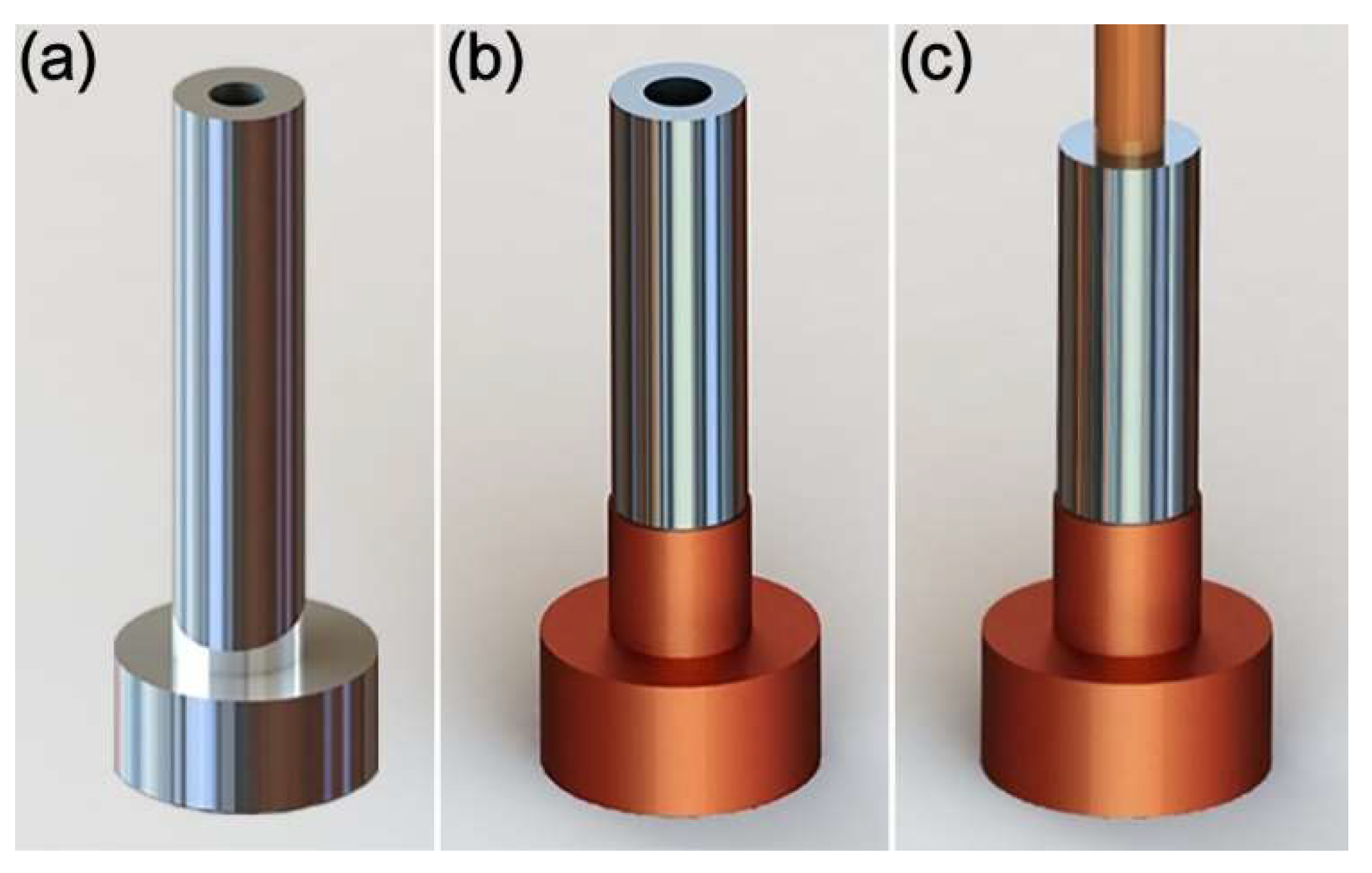
Figure 2.
The instrumentation for thermoplastic forming MG HMs: (a) The heating tungsten filament in a ceramic holder; (b) Schematic illustration of instrumentation of the thermal forming technique; (c) The constant heating current (I) and time (t); (d) The working interface of the LabVIEW program which can be found in the Supplementary File.
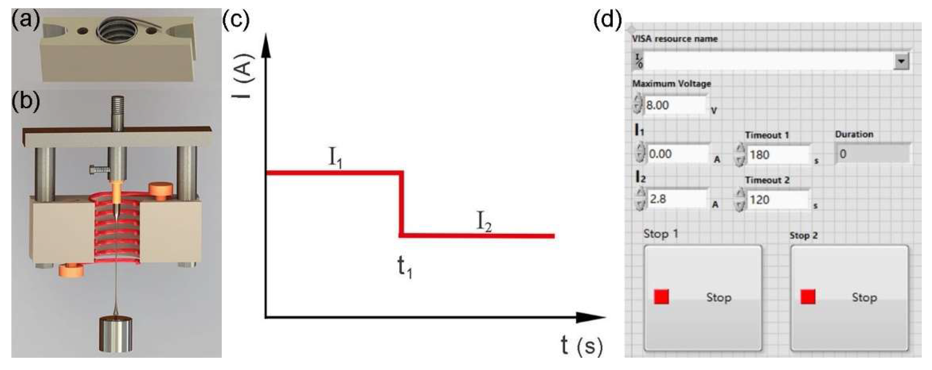
Figure 3.
The relationship between heating current (I1) and heating duration (t).
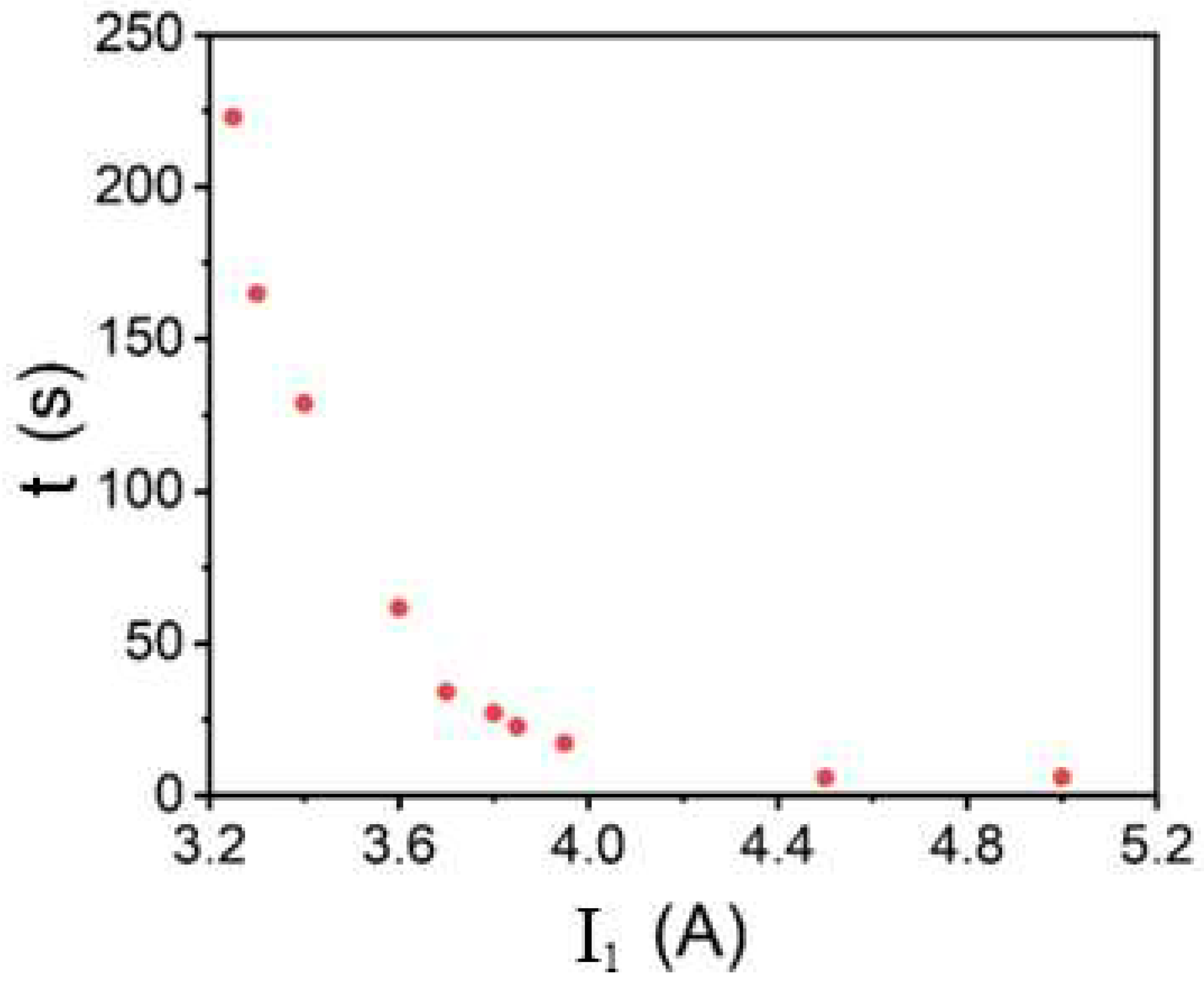
Figure 4.
Morphology of the MG HMs. (a) Preform-to-fiber drawing. (b) Cross-section of an MG HM with a single channel. (c) Cross-section of an MG HM with a double channel. (d) Cross-section of an MG HM with a triple channel. (e) Selected area electron diffraction pattern of an MG HM. (f) High-resolution TEM image of an MG HM.

Figure 5.
Heterogeneous microstructure of an MG HM. (a) The nano-CT g image of a single channel MG HM. (b) The g versus the distance (x) to the left end of the dashed line in (a).
Figure 5.
Heterogeneous microstructure of an MG HM. (a) The nano-CT g image of a single channel MG HM. (b) The g versus the distance (x) to the left end of the dashed line in (a).
Publisher’s Note: MDPI stays neutral with regard to jurisdictional claims in published maps and institutional affiliations. |
© 2022 by the authors. Licensee MDPI, Basel, Switzerland. This article is an open access article distributed under the terms and conditions of the Creative Commons Attribution (CC BY) license (https://creativecommons.org/licenses/by/4.0/).
Share and Cite
MDPI and ACS Style
Zhao, J.; Yi, J.; Huang, B.; Wang, G. Metallic Glassy Hollow Microfibers. Metals 2022, 12, 1463. https://doi.org/10.3390/met12091463
AMA Style
Zhao J, Yi J, Huang B, Wang G. Metallic Glassy Hollow Microfibers. Metals. 2022; 12(9):1463. https://doi.org/10.3390/met12091463
Chicago/Turabian StyleZhao, Jing, Jun Yi, Bo Huang, and Gang Wang. 2022. "Metallic Glassy Hollow Microfibers" Metals 12, no. 9: 1463. https://doi.org/10.3390/met12091463
Note that from the first issue of 2016, this journal uses article numbers instead of page numbers. See further details here.