Review

A Review of Top Submerged Lance (TSL) Processing—Part II: Thermodynamics, Slag Chemistry and Plant Flowsheets

1
TU Bergakademie Freiberg, Institute of Nonferrous Metallurgy and Purest Materials (INEMET), Leipziger Straße 34, 09599 Freiberg, Germany
2
Department of Engineering Technology and Didactics, DTU Engineering Technology, Technical University of Denmark, Lautrupvang 15, 2750 Ballerup, Denmark
3
TU Bergakademie Freiberg, Institute of Energy Process Engineering and Chemical Engineering (IEC), Reiche Zeche, Fuchsmühlenweg 9 D, 09599 Freiberg, Germany
*
Author to whom correspondence should be addressed.
Metals 2023, 13(10), 1742; https://doi.org/10.3390/met13101742
Submission received: 3 August 2023 / Revised: 27 August 2023 / Accepted: 14 September 2023 / Published: 13 October 2023
(This article belongs to the Special Issue Metal Extraction/Refining and Product Development)

Abstract

:
In Part II of this series of review papers, the reaction mechanisms, thermodynamics, slag chemistry and process flowsheets are analyzed concerning cases where the TSL bath smelter has found its application. These include the primary and secondary production routes of five non-ferrous metals (tin, copper, lead, nickel, zinc), ironmaking and two waste-processing applications (spent pot lining and municipal solid waste/related ash treatment). Thereby, chemistry and processing aspects of these processes are concisely reviewed here, allowing for clear and in-depth overview of related aspects. In contrast to Part I, the focus lies on a holistic analysis of the metallurgical processes themselves, especially the particularities induced by carrying them out in a TSL reactor rather than on the respective equipment and auxiliaries. The methodology employed per metal/application is presented briefly. Firstly, the feed type and associated statistical information are introduced, along with relevant process goals, e.g., the secondary metallurgy of copper involves the recovery of platinum group metals (PGMs) from waste from electrical and electronic equipment (WEEE). Subsequently, associated chemistry is discussed, including respective chemical equations, analysis of the reaction mechanisms and phase diagrams (especially of associated slag systems); these are redrawn using FactSage 8.1 (databases used: FactPS, FToxid, FTmisc, FTsalt and FTOxCN) and validated by comparing them with the literature. Then, based on the above understanding of chemistry and thermodynamics, the flowsheets of several industrial TSL plants are introduced and discussed while providing key figures associated with process conditions and input/output streams. Finally, this article culminates by providing a concise overview of the simulation and digitization efforts on TSL technology. In light of the foregoing discourse, this paper encapsulates basic principles and operational details, specifically those pertaining to TSL bath smelting operations within the non-ferrous industry, thereby offering valuable insights intended to benefit both scholarly researchers and industry professionals.

1. Introduction: Process Flowsheets and Reactions for Individual Metal Processing Using TSL Technology

The TSL technology is used to produce a wide range of materials due to its flexibility (as discussed in Part I). In order to illustrate the discussion of Part I, Part II will discuss the implementation of TSL technology in various primary, secondary and recycling flowsheets all over the world. Therefore, this paper will project how TSL technology can recover and distribute metals, compounds and materials through suitable flowsheets. Thus, TSL plays a key role in closing the loop of metals in the circular economy [1,2,3,4,5].

2. Tin

Tin slag reduction and high-grade tin concentrate smelting are processes that were primarily carried out with use of TSL technology (i.e., SIROSMELT) in the 1970s. Today, the TSL technology produces more than 55% of the world’s tin (see Appendix in Part I for tin concentrate annual feed throughput for individual TSL plants). The initial experiments were carried out concerning tin recovery from slags produced during the conventional reverberatory smelting of high-tin concentrates from the company ATS in Australia. Tin concentrate smelting was patented (US 3,905,807) by CSIRO, Australia for high-grade alluvial concentrates (loose, unconsolidated soil or sediment that has been eroded, reshaped by a water stream, e.g., rivers [6]) and later modified to allow smelting of lower-grade mill concentrates. TSL smelting is generally utilized to process medium-grade concentrates (40–60 wt.-% Sn) since the amount of resulting slag can be dealt with adequately [7]. According to the same reference, higher-grade concentrates are still smelted in reverberatory furnaces due to the small slag amount produced; in comparison, lower-grade concentrates would be more suitable for fuming. Although TSL furnaces could be utilized for the fuming process, no commercial plant reference exists to date. In general, tin concentrates are oxidic, and the tin-containing mineral is cassiterite (SnO2).

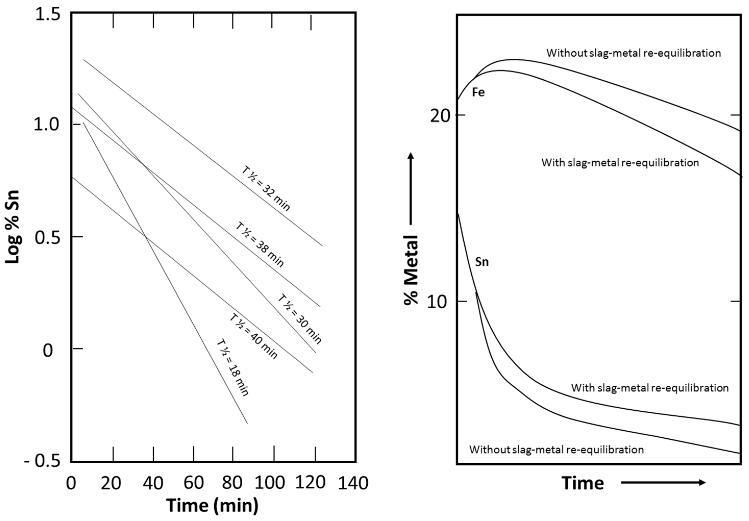
2.1. Reactions and Chemistry within the Tin System

Tin production proceeds through a smelting stage and slag reduction stage. In general terms, the most important equilibrium, which defines the two-stage nature of the processes, is given in Equation (1).
SnO (slag) + Fe (metal) → Sn (metal) + FeO (slag)
A distribution coefficient (D), which essentially is associated with the equilibrium constant and activity coefficients of the above reaction, is shown in Equation (2) [8].
D = w t . - %   S n   i n   m e t a l w t . - %   F e   i n   m e t a l * w t . - %   F e   i n   s l a g w t . - %   S n   i n   s l a g
The distribution coefficient (D), according to [8], exhibits values of 150–400 for concentrate smelting (first process stage), where a crude Sn metal with <2 wt.-% Fe and a tin-rich slag are produced. As further explained, the latter aspect combined with a value of D = 200 at 1200 °C results in a  F e ( w t . - % ) / S n w t . - %  ratio in the slag of about 4. The high tin content in the slag justifies the need for a slag reduction stage (second process stage). This stage produces a hardhead (Sn-Fe alloy) of 10–60 wt.-% Fe and a disposable slag, the value of D is 20–50 at 1400 °C (temperature level associated with reverberatory furnaces).
Figure 1 refers to TSL slag reduction (second process stage), where the half-time for reduction is shown for tin in the slag system (present as SnO), which ranges from 18–40 min [9]. According to the same reference, the scattering of the lines is associated with difficulty to control coal rate (serving as reductant and heat source) and aspects associated with the off gas system within industrial-scale plant trials. If the above issues are not present, half-time reduction is achieved for slag reduction down to 0.4 wt.-% Sn, within 15–20 min. Essentially, Equations (1) and (2) apply to both the TSL and reverberatory furnace. However, the better performance of the TSL furnace in producing a lean tin discard slag can be understood due to the low apparent reaction rate of Equation (1) (in the reverse direction) within the lower region of the TSL, where slag rests upon the produced metal alloy [10]. As explained, the TSL can be operated at such a position that allows “coalescence” of the produced metal phase droplets within the slag, thereby ensuring quick transfer to the metal phase at the reactor bottom, thus minimizing the occurrence of Equation (1) towards the left side (i.e., SnO and Fe formation is hindered). This “better” resulting performance of the TSL is illustrated on the right side of Figure 1; when Equation (1) is not at equilibrium, a discard slag leaner in tin and richer in iron content is produced. Finally, fuming can treat residual slag and recover tin after slag reduction. According to [8], a carbonaceous reductant and “sulfurizing agent”, e.g., pyrite, is required to produce SnSx (fume), which can be oxidized to SnO2 and recycled to the process feed.

2.2. Commonwealth Scientific and Industrial Research Organization (CSIRO)

The first commercial application of TSL processing was associated with tin reverberatory furnace slag in 1978 at ATS by CSIRO, Australia [7]. A detailed analysis of the experience of the ATS plant is given in [9]. The corresponding slag reduction flowsheet is shown in Figure 2 [9]. The smelting stage producing crude tin metal with a limited amount of iron occurs in a reverberatory furnace. The second (slag reduction stage), producing the hardhead Sn-Fe alloy to be recycled to the reverberatory furnace and a slag lean in tin, occurs in a TSL. Iron in the hardhead Sn-Fe alloy acts as a reductant in the reverberatory furnace, according to Equation (1).
According to [9], several aspects highlighting tin slag reduction are listed in the remainder of this paragraph unless stated otherwise. The SIROSMELT lance (see Part I of this paper for a more detailed description) was simple with two concentric pipes for diesel fuel and air. The diesel was atomized using the “Monarch” nozzle at a supply pressure of 700 kPa (7 bar) and compressed air at 350 kPa (3.5 bar). The refractory linings were chrome-magnesite on the inner side, followed by high-alumina bricks and ceramic fiber blankets. Feed slag constituents to the 2nd (TSL) stage are reported as follows: 15 wt.-% Sn, 22 wt.-% Fe (both in oxidic form), 25 wt.-% SiO2, 4–10 wt.-% CaO as well as noteworthy amounts of Al2O3, TiO2 and MnO. Coal was fed as a reductant in the TSL (additionally to the diesel fuel). The process temperature ranged from 1200 to 1300 °C. The tin was fumed during operation, as SnO (gas) was 10 to 20% for molten slag feed and 20 to 25% for solid slag feed. Both molten and solid slag feed were possible; however, the latter led to increased fuel consumption and cycle time. An after-burner was required to combust reducing gases (e.g., CO, H2); a drop-out box was utilized to collect fumes; the gas was cooled before being emitted. In 22 batches, a discard slag with an average of 0.96 wt.-% Sn and 20.1 wt.-% Fe was produced. Respective ranges noted were 0.4–1.3 wt.-% Sn and 17.9–24.2 wt.-% Fe. Below 0.4 wt.-% Sn slag content, a solid Sn-Fe alloy was formed, which led to tin being lost in the slag due to entrainment. Considering the necessity to not “overreduce” or “underreduce” the slag, the goal for residual tin in the discard slag was set to 1–2 wt.-%. Residual slag content from reverberatory furnaces exhibits a lead slag content of 1.5–3 wt.-% [8].
Realizing both process stages (concentrate smelting and slag reduction) in a single vessel is described in [9] as follows. Crude tin and tin-rich slag are produced in the first stage (smelting), while crude tin is removed from the furnace. The tin-rich slag is reduced in the second stage while producing hardhead, which remains in the furnace to serve as a reductant (discussed earlier) during the next smelting stage, and a lean tin slag is disposed of. The apparent benefit of the “one-vessel process” is that slag granulation, stockpiling and resmelting are avoided. Since a single furnace suffices instead of two, fugitive emissions are avoided. Resmelting between the stages has been necessary in pre-TSL times to mix a carbonaceous reductant with the slag. In addition, for the carbothermic reduction to be successful, a temperature of 1400 °C was applied, as previously mentioned. The TSL can utilize liquid or gaseous reductants, resulting in bubbles with a high reductant species concentration. The bubble interface offers a large surface area between reductants and slag. Mixing between slag and reductants occurs through turbulence imposed from blowing gas through a lance into the bath. Thereby, temperatures more than 1300 °C are not necessary.
Figure 2. ATS slag reduction flowsheet (redrawn with permission) [9].
Metals 13 01742 g002

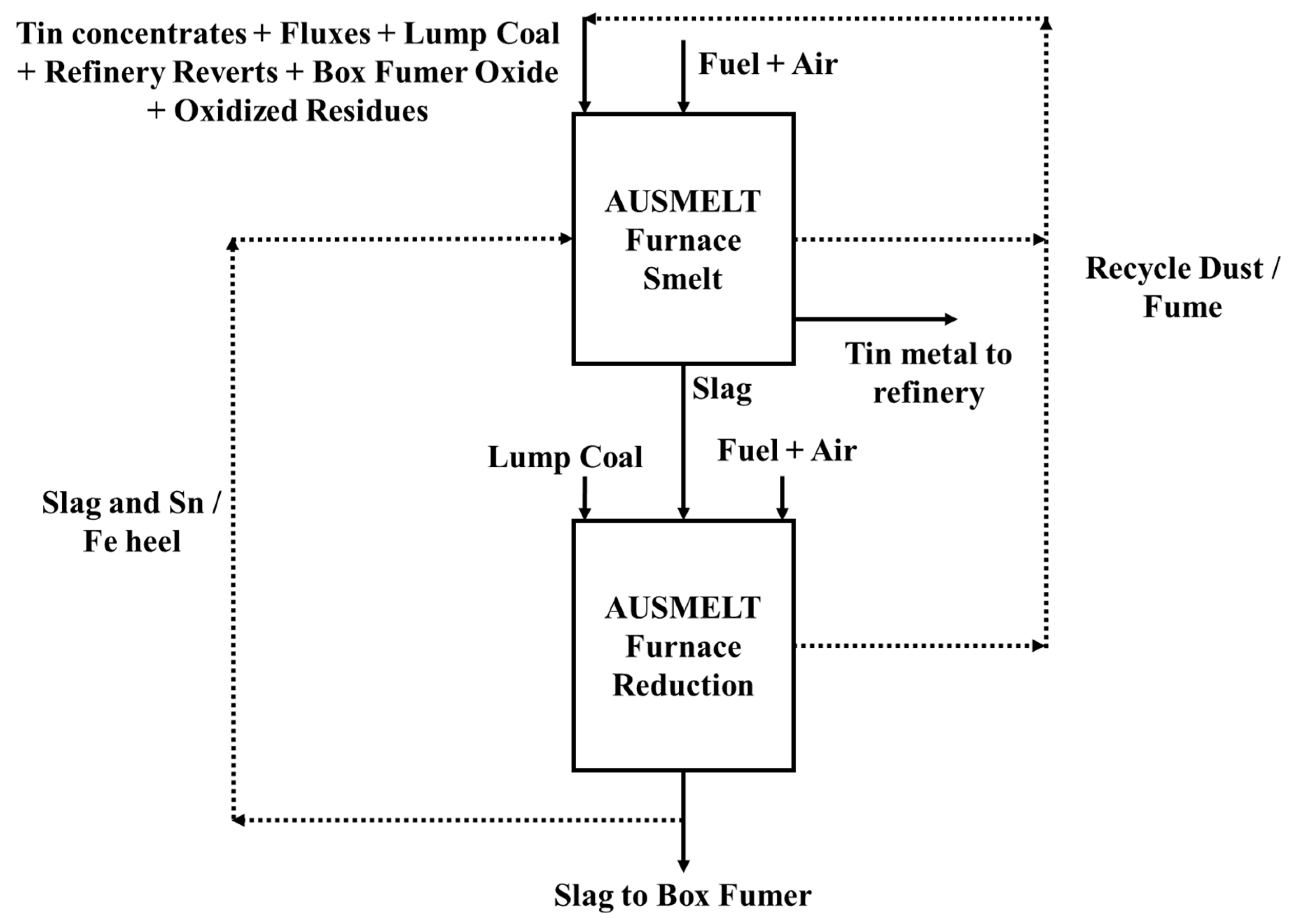
2.3. Further Tin Applications Using TSL Technology

TSL technology was implemented by Guangxi China Tin Group Co., Ltd. (China Tin, Laibin, China) by replacing three reverberatory furnaces in 2015 [7,11]. In the block diagram of Figure 3, both “furnace smelt” and “furnace reduction” stages are conducted in a single vessel [7]. As discussed, roasted cassiterite (SnO2) feed is used to produce 17,500 tons per year of tin in crude bullion (96 wt.-% Sn, i.e., first stage). The above amount does not include recycled and revert feed components. In the reduction stage, a slag with low levels of Sn (3 wt.-%) is produced. The slag is further processed to increase the recovery through fuming, as shown in Figure 3. Finally, fumes from all process stages are recycled to the feed of the smelting stage.
In Bolivia, the Vinto smelter is in operation with a design capacity of producing 38,000 tons of tin annually [7,11]. As discussed in [11], two further applications had been discussed in terms of being operable from 2022–2023, i.e., PT TIMAH (Indonesia) and the Malaysian Smelting Corporation. The latter involves the conversion of a lead-smelting TSL to a tin-processing furnace [11]. From a CO2 emission reduction perspective, the utilization of natural gas instead of HFO, within the TSLs at Minsur in Peru, for both smelting and reduction stages, led to a 10% reduction in process CO2 emissions, while the use of H2 had been considered as far back as the late 1970s [12].
Figure 3. AUSMELT smelting flowsheet implemented at largest TSL tin smelter with 100,000 tpa (Yunnan Tin Corporation Ltd. (YTCL), Datun, China) (redrawn with permission) [13].
Metals 13 01742 g003

3. Copper

3.1. Reactions and Chemistry within the Copper System (Primary Production)

3.1.1. Matte Smelting

The simplified smelting reaction may be expressed as shown in Equation (3) [14], where x depends on the O2 flow rate/feed rate for a given concentrate, which defines the matte grade [15].
2 CuFeS2 (solid) + (1 + 1.5 x) O2 (gas) + x SiO2 (solid) → Cu2S-(FeS)2−x (matte) + x FeO·SiO2 (slag) + (1 + x) SO2 (gas)
The TSL furnace is a reactor where oxidative gas is blown within the slag phase, contrary to Noranda/El Teniente tuyere bath smelters, where the above reaction occurs in the matte phase [15,16]. In the TSL furnace, “slag blowing” also leads to a different reaction mechanism when compared to the flash smelter. In the latter case, the feed can be over- or underoxidized when traveling through the burner port and reactor shaft [17]; respective corrections are undertaken through the Cu2O + FeS → Cu2S + FeO equilibrium, which does not favor too much Cu2O slag (at moderate Cu matte grades) [15]. An explanation of the slag’s role as an “oxygen conveyor” in a TSL furnace, according to [18], is shown in Figure 4. The concentrate feed (e.g., chalcopyrite, CuFeS2) reacts with the dissolved magnetite, according to Figure 4. The term “liquid oxygen” has been used instead of “dissolved magnetite” [19]. The components produced involve SO2 gas, the matte species (Cu2S, FeS) and the slag species FeO. The Fe2+ is reoxidized to Fe3+ due to the oxidizing gases blown through the lance, allowing the production of further “dissolved magnetite” and hence the mechanism of Figure 4 becomes cyclic.
As postulated within [14], a similar approach is shown within Equations (4)–(7), where chalcopyrite (CuFeS2) first decomposes to Cu2S, FeS and S2 (gas) as a result of heating (see Equation (4)). This reaction is also a redox reaction since Fe3+ or Cu2+ contained in chalcopyrite are reduced to Fe2+ or Cu1+, respectively, while sulfur is oxidized from 2 S−2 to  S 2 0 . According to the authors, Fe2+ (FeO) is oxidized by lance air/oxygen to form Fe3+ (Fe2O3) (see Equation (5)), which reacts with FeS (to FeO), as shown in Equation (6). It is important to note that the magnetite content (~5wt.-%) dissolved in slag is crucial in the TSL copper-smelting operation [14], considering its role as an oxygen carrier. It is also interesting to note that the oxidation of labile sulfur reacts directly with gaseous oxygen, as shown in Equation (7). The latter reaction is rendered complete with the use of “shroud air” (see Part I of this series of papers) injected above the bath surface [15]. According to [20], the turbulence during TSL smelting leads to low levels of copper oxidation, shown in Equation (8). The latter is associated with oxygen being blown into the slag and not directly to the matte, thereby avoiding local copper oxidation. The entrapment of matte “globules” is the predominant mechanism of copper loss (~85% in [21]). Finally, the slag-forming reaction between FeO and SiO2 (included in Equation (3), but not listed explicitly) is documented elsewhere [14], leading to the fayalitic slag phase formation. Equations (4)–(7) have also been discussed within an industrial paper [22] concerning explaining the reaction mechanism.
2 CuFeS2 (feed) → [Cu2S + 2 FeS] (matte) + (1/2) S2 (gas)
2 FeO (slag) + (1/2) O2 (gas) → Fe2O3 (slag)
FeS (slag) + 3 Fe2O3 (slag) → 7 FeO (slag) + SO2 (gas)
S2 (gas) + 2 O2 (gas) → 2 SO2 (gas)
Cu2S (matte) + FeO (slag) → Cu2O (slag) + FeS (matte)
The phase diagram corresponding to the matte phase, at temperature and matte grades which are relevant to TSL operation, is shown in Figure 5 below. As shown by the range of the operating window with regard to attained matte grade, matte grades attempted within TSL smelters are lower than those of other reactors employing high levels of turbulence such as the Noranda-Teniente smelter [16], which also aids TSL smelters to attain a low level of copper oxidation.
The simplified phase diagram associated with the SiO2-FeO-Fe2O3-CaO-Cu2O system at fixed 5 wt.-% CaO, 0.75 wt.-% Cu2O and 1185 °C is shown in Figure 6. The fixed conditions correspond to [23]. However, further slag components are not considered. The equilibrium of the solid magnetite-forming reaction (Equation (9)) is depicted in the phase diagram of Figure 6 as the boundary between the liquid “slag” and the “slag + spinel” regions (to the right of the liquid “slag” region). The latter is unwanted since it leads to a viscous slag, while solid magnetite settles at the bottom of the furnace and is sometimes aggressive towards the refractory (depending on its chemical composition) and hinders matte/slag separation. Matte smelting units usually operate on the above-mentioned boundary. TSL furnaces can tolerate high amounts of solid magnetite due to associated turbulence, not allowing solids to settle. The “division” of the liquid slag area in Figure 6 into a “Slag-liq + Cu (liq)” and a “Slag-liq” area expresses the creation of a copper phase at low oxygen potentials (<10−10 atm; not realistic for matte smelting) due to Cu2O reduction.
In addition, the SiO2/Fe ratio (mol/mol) suggested for AUSMELT and ISASMELT furnaces is in the range of 0.6–0.7 and 0.65–0.85, respectively. Too-low SiO2/Fe ratios have been shown to correspond to high total (dissolved + solid) magnetite content in the slag (i.e., resulting in the high activity of Fe2O3 in the slag, Equation (9)). On the other hand, too-high ratios do not facilitate the reaction mechanism during smelting (shown in Figure 4) and are discussed within Equations (4)–(6) [21]. The SiO2/Fe ratios are mentioned within the dedicated paragraphs below when examining the operation of different industrial plants. On occasion, they differ from the noted ranges.
FeO (liquid) + Fe2O3 (liquid) → Fe3O4 (solid)
Figure 7 depicts the CaO-FeO-SiO2-Al2O3 system at a fixed alumina content of 6 wt.-% and partial pressure of oxygen equal to 10−8.4 atm and has been presented in conjunction with the ISASMELT unit at the ILO smelter in Peru [21]. Aspects discussed in this paper are presented here, combined with additional calculations, to vividly illustrate the importance of slag chemistry in a TSL unit. The original design point of the plant involved ratios of SiO2/Fe = 0.88 and SiO2/CaO = 7.0 at a bath temperature of 1175–1195 °C. The slag liquidus temperature is confirmed at 1195 °C (a point noted in Figure 7); lower operating temperatures mean the presence of a spinel phase to an extent. At the above setpoint, undissolved silica was noted at the ILO smelter, which can be attributed to the size and type of silica. Reduction of the SiO2/Fe ratio leads to less slag production (by 6%) and allows more time for settling in the RHF units. However, it increases the slag’s total magnetite content, while its liquidus temperature is also increased (calculated here to be 1203 °C). Increasing the magnetite content to above 6.5 wt.-% (referring to total dissolved and solid magnetite—as spinel) leads to copper losses above 0.8 wt.-% in the slag as entrained matte due to high slag viscosity. Coal was added to decrease the PO2, thus regulating magnetite content to below 7 wt.-%. A reduction of the CaO flux (seashell), i.e., an increase in the SiO2/CaO ratio to 7.5, resulted in restoring the liquidus to approximately 1195 °C, according to [21]. However, the above measure results in only moderate liquidus temperature reduction according to our calculations shown in Table 1, while respective points are also noted in Figure 7.
Overall magnetite content is influenced by matte grade, SiO2/Fe ratio and operating temperature [21]. Considering that operating temperature is lower than the liquidus temperature, noted in Table 1, the actual magnetite content (without coal addition) would be higher, e.g., 8–10 wt.-% for the setting SiO2/Fe = 0.82 and SiO2/CaO = 7.0 [21]. Thereby, the use of a reductant is justified. Low temperatures are important considering refractory wear; for example, an increase of +15 °C of the operating temperature increases the dissolution of MgO by 30% [25], see Part I of this series of papers. Operation at a moderate temperature of 1190 °C, as noted within [21], did not lead to significant refractory wear. The effect of MgO in copper slags was studied in [26], showing that the addition of MgO in copper slag increases the slag liquidus and viscosity (due to complex silica structure formation). This may hinder the recovery of matte from copper slags in terms of phase separation.

3.1.2. Matte Converting and Respective Slag Systems

Next, we proceed to discuss converting using the TSL and start with continuous converting. Such a process is discussed (patent number: US RE44850E) by AUSMELT, where slag is the reaction medium [27]. Thereby, the importance of slag depth is underlined to disallow oxidation of the blister copper phase. The slag depth may range from a minimum of 0.5 m up to 2 m (and is associated with several factors, including the size and shape of the TSL), preferably about 0.7 m to 1.7 m. The preferred slag region is defined within the patent by the ratios: SiO2/Fe = 0.47–0.87, CaO/Fe = 0.15–0.92 and SiO2/CaO = 0.90–4.55 and corresponds to an FCS slag (see Figure 7 and also Figure 8 for a qualitative phase diagram at 1300 °C and 10−6 atm) [28]. Concerning the reaction mechanism, the authors discuss that an oxygen-containing gas is blown within the slag phase along with entrained matte and flux. The slag phase (of dispersed matte) hosts occurring reactions, while the produced Cu blister phase (density of 7.8 g/cm3 and viscosity of 0.0033 Ns/m2 [24]) is the product phase that collects at the bottom of the vessel. Blister copper is in a “resting” state and does not participate in occurring reactions [28]. A benefit of converting matte fully within the slag phase is avoiding matte–blister reactions (e.g., 2 Cu + FeS → Cu2S + Fe). Finally, the operating oxygen potential defines the relationship between residual sulfur in the blister copper and loss of copper as Cu2O in the slag. The authors of the patent US RE44850E [27] claim that when a residual S is in the vicinity of 0.02–0.03 wt.-%, then a high Cu content in the range of 23–36 wt.-% will result in the slag. On the contrary, if a S content in the blister copper above 0.2 wt.-% is tolerated, then the Cu content in the slag drops to approximately 10–16 wt.-%. Additionally, to avoid foaming, lump coal is added to the system to control the Fe3+ bath content.
Reactions occurring during continuous copper converting considered (generally applicable) when using the TSL are shown in Equations (10)–(13) [29]. The similarity to the mechanism associated with primary smelting (see Figure 4 with regard to the cyclic oxidation/reduction between Fe2+ and Fe3+), thus converting mattes species to blister copper, is evident. The affinity of FeS to dissolved Fe3O4 is greater than that of Cu2S, and hence iron is oxidized (Equation (11)), thus transforming the matte to white metal (Cu2S). Magnetite then oxidizes the latter to metallic Cu (Equation (12)) and partially to Cu2O (Equation (13)). CF slags (see Figure 8 for phase diagram), formed through the reaction between CaO and Fe3O4 [14]), have been discussed with regard to ISACONVERT furnaces [30,31]. Residual sulfur in the blister copper is 0.3–0.4 wt.-% at a slag Cu2O content of 12–18 wt.-% (10–16 wt.-% Cu) [30] and an oxygen efficiency of 100% [29].
6 FeO (slag) + O2 (gas) → 2 Fe3O4 (slag)
FeS (matte) + 3 Fe3O4 (slag) → 10 FeO (slag) + SO2 (gas)
Cu2S (matte) + 2 Fe3O4 (slag) → 2 Cu (blister Cu) + 6 FeO (slag) + SO2 (gas)
2 Cu (blister Cu) + Fe3O4 (slag) → Cu2O (slag) + 3 FeO (slag)
The reaction mechanism is extended, as discussed within [31], when the lance is immersed deep enough within the slag layer so that a part of the oxidative gas reacts with the blister copper. Thus, the solid Cu2O (melting point ~1235 °C) formed can react with matte reaching the blister copper–slag interface. The density of solid Cu2O (6 g/cm3) is less than that of blister copper and higher than that of slag. Cu2O would react similarly to the reverse Equation (8), with the difference that Cu2O is perceived here to be in the solid state. The lance blowing into the blister copper phase also leads to the desulfurization of this phase, potentially through dissolving oxygen within the blister copper. The authors of the aforementioned reference claim that the Cu content achieved in the CF slag (CaO/Fe: 0.15–0.7, CaO/SiO2: 5–10 at 1200–1300 °C) is within a factor of 2, as predicted by the equilibrium reaction given in Equation (14). Respective equilibrium pairs (S in blister copper/Cu in slag as Cu2O) provided at a partial pressure of sulfur (PSO2) of 0.26 atm are reported as follows: 0.4 wt.-% S/~8.2 wt.-% Cu; 0.2 wt.-% S/~11 wt.-% Cu; 0.1 wt.-% S/~15 wt.-% Cu; 0.03 wt.-% S/~30 wt.-% Cu. Lump coal addition is considered to bring about Cu2O reduction [31].
2 Cu2O (slag) + [S] (blister Cu) → 4 Cu (blister Cu) + SO2 (gas)
The composition of CF slags has been given to be equal to 14–16 wt.-% Cu (as Cu2O), 40–55 wt.-% FeOx (mostly contained as Fe3+) and 15–20 wt.-% CaO [16]. A typical composition for an ISACONVERT unit has been given in [30] to exhibit a CaO/Fe ratio of 0.43 at a temperature of 1250 °C. Under copper saturation conditions, the Cu2O content in the slag was influenced by the partial pressure of oxygen (PO2 varied from oxidative atmosphere values of 10−6.5–10−4.5 atm) during converting. The full composition of the slag is given to correspond to: 20 wt.-% CaO, 14.5 wt.-% Cu2O, and 65.5 wt.-% Fe2O3.

3.1.3. Different Types of Slag Systems and Chemistry for Copper Converting

It is interesting to discuss further the slag type utilized regarding matte converting to blister copper. P-S converters utilize fayalitic slags; see Figure 6 for a general overview of the slag system. Matte from the smelter is fed to P-S converters in a batch manner. They operate within the known slag-blowing and copper-blowing steps, removing fayalitic slag after slag blowing is completed. The amount of solid magnetite that would be formed in continuous converting processes (Outotec flash converting, Mitsubishi, AUSMELT C3, and ISACONVERT)—if a fayalitic slag would be used—would make the slag “unworkable”, as it would be too viscous and would lead to high copper losses. These would be attributed to Cu2O and occur through slag entrainment [27]. However, TSL converters generally also operate in batch mode [22,32]. The authors of [33] showed a possibility of reducing the copper losses from converter slags by operating the TSL with controlled atmospheres and by adding fluxes. The continuous converting TSL technology is currently under deployment, as discussed in the following sections. Batch converting operation happens in two steps according to the procedure discussed within [32]. The first step produces high-copper-grade matte (with Equations (10), (11) and (17) taking place). Matte feeding then stops while “excess” slag is removed. Further, according to the authors, the lance injects oxygen-enriched air close to the matte surface during the second step, thereby producing blister copper (with Equations (10) and (12)–(19) being relevant). Considering the proximity of blowing oxygen-enriched air to the matte during the second stage, direct matte oxidation forming Cu or Cu2O should be considered, as shown in Equations (15) and (16), in addition to Equations (12) and (13). Carbon reduction reduces slag viscosity, the possibility of slag foaming (Equation (17)) and copper content in the slag (Equation (18)). According to the PO2 during converting, the off gas will exhibit a PCO/PCO2 ratio defined by the equilibrium of Equation (19). In the case of batch converting, fayalitic slag can be used.
Cu2S (matte) + O2 (gas) → 2 Cu (blister Cu) + SO2 (gas)
Cu2S (matte) + 1.5 O2 (gas) → Cu2O (slag) + SO2 (gas)
Fe3O4 (slag) + C (solid) → 3 FeO (slag) + CO (gas)
Cu2O (slag) + C (solid) → 2 Cu (blister Cu) + CO (gas)
CO (gas) + 0.5 O2 (gas) → CO2 (gas)
CF slags have been mostly considered with regard to ISACONVERT applications [30], as mentioned above. The use of the CF system (represented by the Cu2O-FeO-Fe2O3-CaO system), in equilibrium with the blister copper phase, is most stable with regard to solid magnetite precipitation at oxygen potentials relevant for converting [34]. Respective phase diagrams can be found in [16,30,34]. The operation within the liquid slag area is maintained, despite varying the partial pressure of oxygen. The liquid slag area is limited by the primary phase fields of lime, spinel and dicalcium ferrite. In summary [16], the authors conclude that the following applies for CF slags:
  • Magnetite is not formed in this slag system because the activity of Fe2O3 is lowered.
  • The possibility of slag foaming is minimized.
  • Copper loss is low because of the increased activity of Cu2O.
  • Acidic oxides (As2O3, Bi2O3, Sb2O3) are more easily removed due to the calcium ferrite slag being more basic.
  • They exhibit low solubility with regard to SiO2; this can be understood when plotting calcium ferrite slags within the SiO2-CaO-FeOx phase diagram, as shown in Figure 8.
  • Calcium ferrite slags are aggressive towards MgO-Cr2O3 refractory lining.
The last two disadvantages have brought about the development of FCS slags [15]. FCS slags, as noted above, are deemed most suitable for application within AUSMELT C3 continuous converters [28]. All slag systems discussed are presented qualitatively with the use of the FeOx-CaO-SiO2 system (see Figure 8) at a partial pressure of O2 of 10−6 atm and a temperature of 1300 °C. It is interesting to note that the “liquid slag + spinel phase”, evolving around the FeOx corner of the phase diagram of Figure 8, is minimized due to the presence of Cu2O in the slag [28]. A significant body of work on understanding the FCS slag system has been realized by the Pyrosearch Group, University of Queensland, Australia, within the context of potential utilization of this slag system within ISACONVERT, e.g., [35]. The advantages of this slag system are summarized in [28]. A direct comparison between the slag types is shown in Table 2 [36]. As noted, the main advantage of FCS slags is that they are less aggressive towards the refractory. Additionally, they are similar to the “industry standard” fayalitic slags [16].
Figure 8. A simplified representation of converting slag systems at 1300 °C with 17.6 wt.-% Cu2O at a PO2 = 10−6 atm (areas higher in Fe3+ noted) (redrawn with permission from The Minerals, Metals & Material Society) [28].
Metals 13 01742 g008

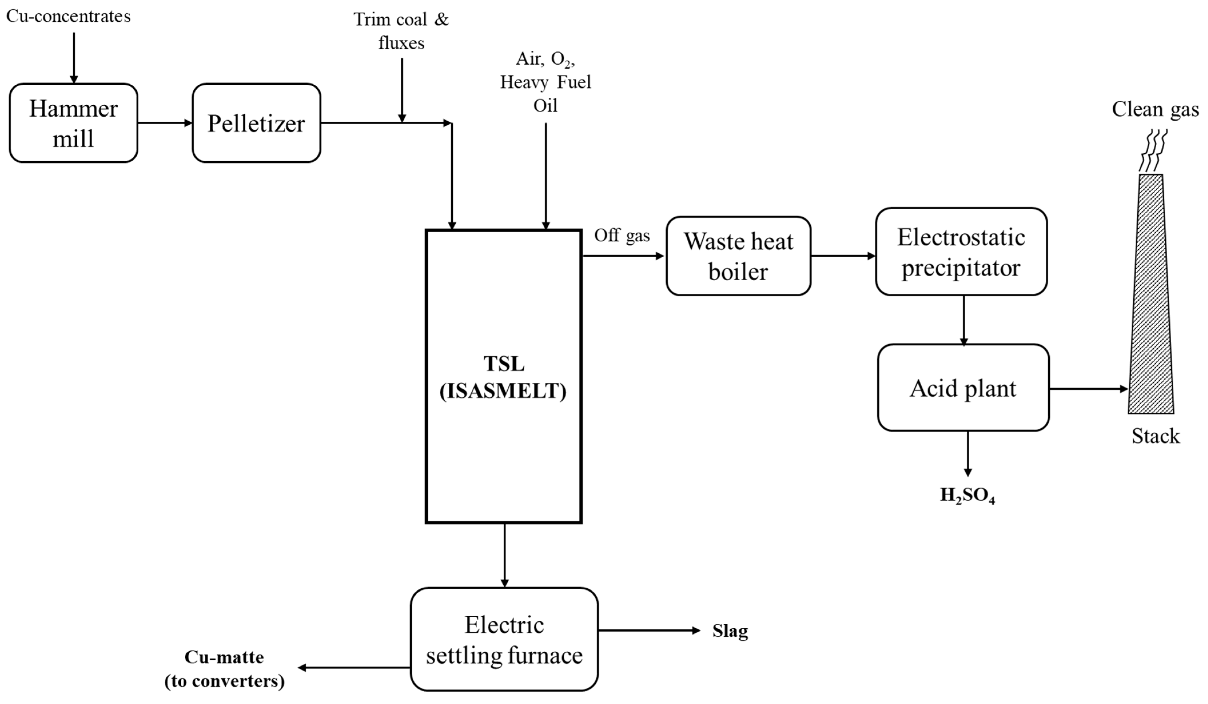
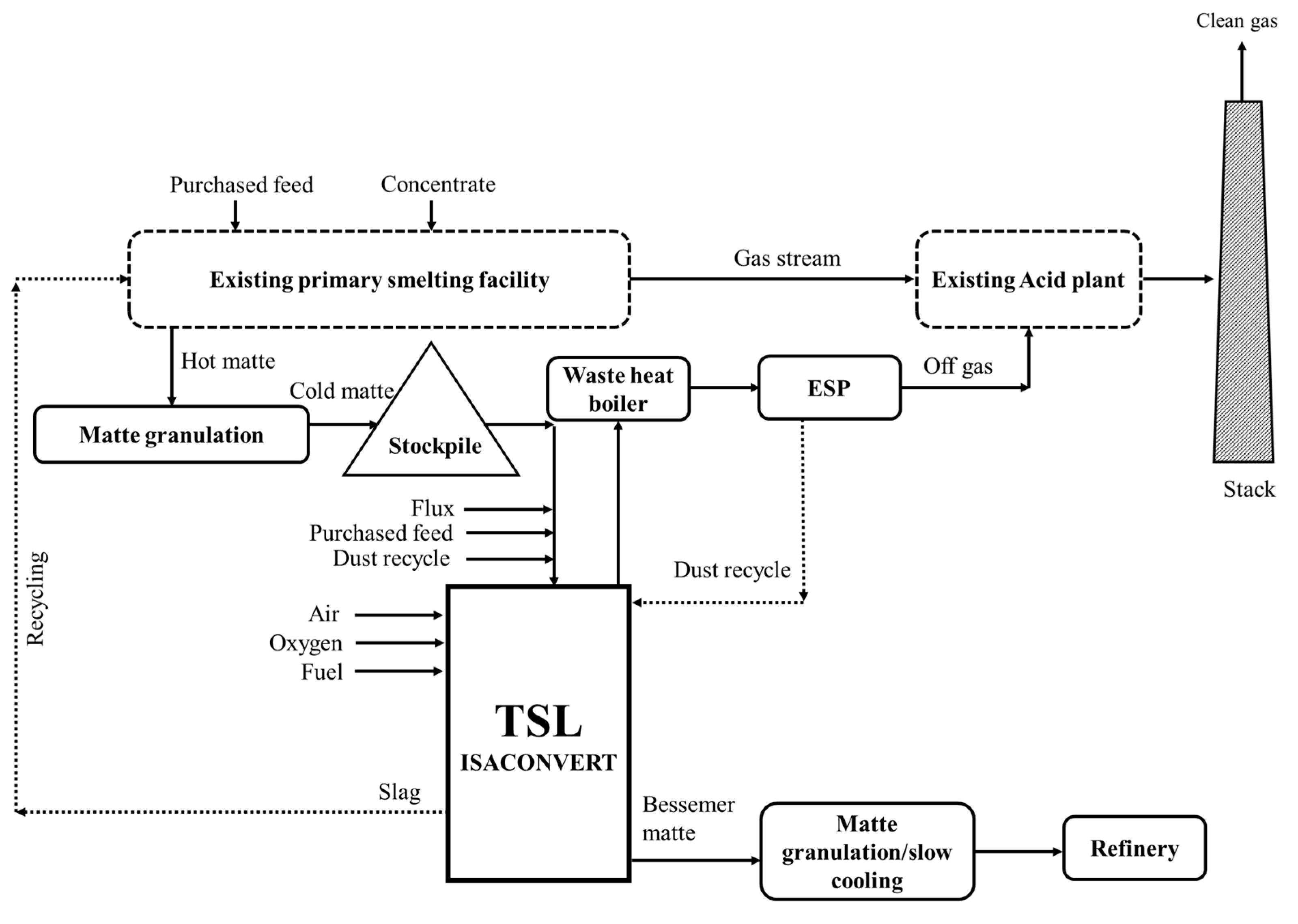
3.2. ISASMELT and ISACONVERT: Primary Copper Smelting and Converting

Many large-scale ISASMELT copper smelters (e.g., Mount Isa Mines (Australia), Southern Copper Corporation (Peru) and Vedanta (India) have capacities over 1 million tpa feed throughput) were built around the world (see Part I of this series of papers). The operation is described in this section using the example of the YCC plant in China. The coal pelletized moist feed and fluxes are fed via an overhead conveyor to the furnace. The solid feed material is pelletized using disc pelletizers. Oxygen-enriched air is given through the lance to the TSL smelter. HFO is also added to adjust the furnace temperature. Through water-cooled tapholes, molten slag and matte are forwarded to the settling furnace, where they are separated. Matte is processed in P-S converters. The off gas is sent to the WHB, followed by an electrostatic precipitator that provides clean gas to an acid plant for wet gas cleaning and sulfuric acid production. Operational data following the first months of commissioning (in 2002) indicated process stabilization at a feed rate of approximately 60 t/h, producing a matte grade of around 60 wt.-% at a SiO2/Fe ratio around 0.88–0.92, and a lance life of above ten days at minimized oil consumption [37]. By applying best practices, Mount Isa have reported that their copper TSL has achieved 900 h of lance life [38].
As discussed in Part I of this series of papers, ISASMELT units typically use RHFs for matte/slag separation, which is in contrast with the above example (see Figure 9). These can rotate to pour matte or fayalitic slag for further processing. A paper [21] from the ILO smelter in Peru discussed copper losses from these furnaces while noting their technical aspects: 15.3 m long, 4.7 m in diameter, energy supply through oxygen/fuel burners, accretion removal through pig iron addition. Operational aspects of this smelter have already been extensively discussed above; see also Figure 7. Further aspects associated with the RHF operation that influence copper loss in the slag include the matte bath depth as it influences the metal carry over with the slag, slag pouring time and temperature. The latter is controlled to 1180–1200 °C to allow good settling of the matte through the slag [21].
With regard to continuous copper matte converting, an application of the ISACONVERT is at Kansanshi Copper Smelter, Zambia. This first industrial plant (125,000 tpa—blister copper), operated by FQM, was commissioned in 2019. Operating figures are 12 t/h of granulated matte feed at 60 wt.-% Cu grade, limestone feed of 1.2 t/h, production of 5.4 t/h blister copper (99.5 wt.-% Cu, 0.3 wt.-% S, 0.2 wt.-% O), 3.6 t/h of slag (18 wt.-% Cu2O), 9000 Nm3/h off gas after the WHB (15% SO2, 11% H2O and 1.5% O2) [21].
Additionally, TSL smelters could be coupled with different converter types utilizing different slag chemistry, as shown in Figure 10. Hence, the combination of a TSL smelter with P-S converters (batch) using fayalitic slag or a TSL converter operating continuously with CF or FCS slags has been considered. In the case of fayalitic slag, CF and FCS slags, the required fluxes are SiO2, CaCO3 and SiO2 + CaCO3, respectively. A noteworthy point of Figure 10 is the matte grade of 70 wt.-%, which is higher than noted in the previous sections (see also Figure 5) and projected in [16].

3.3. AUSMELT and C3 Converting: Primary Copper Smelting and Converting

Eleven AUSMELT units had been noted in a 2016 publication, with a combined capacity of 6 million tpa feed throughput [32]. The flowsheet of Cu primary smelting is discussed in an article [20], with the flowsheet shown in Figure 11. Essentially, this flowsheet, characterized by two furnaces and continuous smelting operation, was realized in China by the company ZTS in 1999 [22], where 17–22 wt.-% Cu concentrate is processed. The capacity of ZTS is about 200,000 tpa of feed throughput. However, no matte stream exits the TSL smelting furnace (in contrast to Figure 9 [20]), and hence the matte/slag stream exiting the unit via an underflow weir enters the settling furnace (90 t matte-holding capacity). The matte (60 wt.-% Cu) is transferred to the TSL converting furnace in the molten state. The slag (0.6 wt.-% Cu) is removed continuously from the settler and is granulated. The converting operation happens in two steps, producing blister Cu at 0.1–0.2 wt.-% S and slag with 15 wt.-% Cu that is recycled to the smelter. The possibility of a single TSL furnace for smelting and converting had been discussed; however, such operation is not feasible for smelters handling more than 100,000 tpa of concentrates.
The procedure of batch converting is further described within [40], with regard to the Yunxi Copper converter—found in [32] as YTC (Yunnan Province, China). The furnace treats 100,000 tpa of 60 wt.-% of “water-quenched” Cu matte. Matte converting happens in 8 h cycles (270 t of matte/cycle). The first stage, termed as “slagging”, lasts 5 h and produces high-grade matte at 1300 °C and SiO2/Fe = 0.58, and slag (14 wt.-% Cu) is tapped three times. The second stage lasts 2 h and produces blister copper (0.5 wt.-% S) at 1270 °C. The last stage involves blister copper discharging. The low copper content in the slag is justified based on tolerating a certain amount of FeS at the end of slagging and by slag reduction [40].
The biggest AUSMELT primary copper TSLs are at Daye Nonferrous Metals Company Ltd., China, with 1.5 million tpa (210 t/h) feed throughput. Matte/slag is continuously tapped through an underflow weir for subsequent separation in the ESF. Further aspects of the Daye Nonferrous Metals Company Ltd. plant mentioned in [23] are: a furnace diameter and height of 5 m and 16 m, respectively, overhead feeding of concentrate (210 t/h), lump coal and flux (to create a fayalitic slag of SiO2/Fe = 0.76 with 5 wt.-% CaO), fine coal and oxygen-enriched air (60%) through the lance, a WHB to cool 120,000 Nm3/h from 1100 °C to 350 °C (thus producing 110 t/h of steam), a combined sulfuric acid production of 970 kt/a through two double contact acid plants, residual copper content in the slag from the ESF is 0.75 wt.-% Cu, three P-S converters, two anode furnaces and two casting wheels. The furnace temperature is 1185 °C +/− 10 °C, and lance tip repairs (at 60% O2) are realized every 3–4 days. Availability of 90% is reported, with a 2–3-week stop annually for refractory partial relining [23].
The AUSMELT C3 process (in full: continuous converting process) utilizing the aforementioned FCS slag systems has been demonstrated at pilot plant scale for several 8 h campaigns, which varied slag composition (Cu content at approximately 17.6 wt.-%), temperature (1250–1350 °C) and partial pressure of oxygen (10−8 to 10−6 atm) [28]. TSL feed throughput values above 150,000 tpa can be achieved in a single vessel [32]. The process has been demonstrated at the aforementioned ZTS smelter [28,32] as well as the Yunnan tin smelter. Experiences from the full process demonstration at ZTS (compared to the batch-converting process) involve a 35% capacity increase in matte feed throughput, better slag fluidity, reduction concerning accretions and greater ease with regard to tapping, while optimization of fluxing allowed minimization of produced slag and hence of copper loss in slag [28].

3.4. Trends concerning Primary Copper Production

3.4.1. Handling of Impurities

Impurities like arsenic and antimony constitute an important aspect with regard to their impact on copper smelting, health and environmental issues. More than 30% of the mines were shown to produce arsenic concentrates above 0.1 wt.-%, while mines like Chelopech (Bulgaria) or Marcapunta (Peru) produce arsenic-containing concentrates with 6 wt.-% As and 8 wt.-% As, respectively [41]. Typically operating at lower O2 enrichment values than flash smelters, TSL smelters may avoid high local oxygen potentials. This enhances impurity volatilization (for example, As3+ forms volatile species, while As5+ does not). Even at the same oxygen enrichment values as flash smelters, TSLs may lead to higher impurity removal due to achieving vol.-% values in the off gas (e.g., for arsenic compounds) closer to gas saturation [42]. A further aspect to consider is the low carryover of feed (i.e., low dust generation) as a result of moist/coarser concentrate overhead addition, which is a crucial property since dust “collects” impurities through chemical reactions (e.g., arsenates) or condensation. The Daye smelter mentioned above demonstrates feed entrainment of below 0.5% [23]. Other sources note up to 1% for primary TSL smelting. In comparison, this number from flash smelters is equal to 4–10% [15]. Additionally, highly reducing conditions as part of slag cleaning are not required, which could drive impurities from the slag to the matte phase while aiming to recover copper [42]. Based on thermodynamic simulations, within the latter reference, TSL smelting could be suitable for concentrates with an arsenic content even as high as 3 wt.-%.
Results from the Mount Isa ISASMELT furnace (operating with 194 tph concentrate at 8 wt.-% moisture) with regard to the partitioning of minor elements are shown in Table 3. The slag is characterized by a SiO2/Fe ratio of 0.85. As further discussed, arsenic partitioning to the gas increases with arsenic content within the feed. However, this also leads to the increase in arsenic in matte and slag phases (in absolute numbers). Lead predominantly reports to the matte in contrast to zinc, which reports mainly to the slag. Cobalt distributes similarly between matte and slag. Antimony volatilization is aided in the TSL considering the presence of moisture and the gas volume [42].

3.4.2. TSL Furnace Optimization

Optimization of the TSL regarding fossil fuel consumption, CO2 emissions, electrical energy consumption, campaign life and capital cost was deemed necessary to maintain competitiveness [32]. Technical suggestions by the authors were:
i.
High levels of oxygen enrichment blown through the lance: Levels up to 80% can be realized today (regarding primary smelting), which results in lower electricity/energy consumption. In addition, compressed air, off gas processing and a more concentrated SO2 stream are beneficial for sulfuric acid production. Therefore, existing plants can increase their capacity, e.g., an increase in oxygen enrichment from 40% to 52% led to an increase in the feed rate in the Tongling Jinchang smelter (AUSMELT) from 48 t/h to 120 t/h. With regard to continuous converting, oxygen enrichment of 52% has been suggested [43].
ii.
Cooling of the furnace: For example, water-cooled copper elements employed in different parts of the TSL furnace will increase the refractory life; thereby, less maintenance is required (see original reference and Part I of this series of papers for more details).
iii.
Dried feed: A reduction of 20–35% in energy consumption can be achieved through the utilization of steam in the WHB to reduce the feed moisture content to 1 wt.-%. Such dried feed can be injected through the lance, hence reducing fossil fuel consumption associated with the latent heat of the water and reducing off gas volume (and thus electricity consumption). Alternatively, only partial drying of the feed to 8 wt.-% has been considered, which can be added to the furnace via overhead feeding [43].
Interestingly enough, according to the discussion realized in the previous paragraphs, some of the measures mentioned above, i.e., high oxygen enrichment and “bone dry” feed, may be counter-productive for impurity removal. A more detailed mass and heat balance calculation considering the above measures has been realized within [43]. Furthermore, the authors examined additional measures that could lead to more sustainable processing. These include [44]:
  • avoidance of carbonaceous fuel addition in the ESF, or
  • using a slag cleaning furnace and utilizing a concentrator plant (milling and flotation) to recover copper from the slag and the use of continuous converting or,
  • finally, the carbon–lean natural gas fuel can be applied for primary copper smelting, as proven by JSC Karabashmed, Russia.

3.4.3. Direct-to-Blister Copper

The possibility has been considered of using ISASMELT for a “direct-to-blister” process with regard to concentrates that are low in iron, i.e., those which are rich in bornite (Cu5FeS4) or chalcocite (Cu2S) [16]. CF slag is not considered here due to the slag system’s low tolerance to SiO2, a topic already discussed above. However, typical FCS systems are criticized due to the possibility of causing foaming at an oxygen potential of 10−6 atm. Hence, a narrow slag region is identified and coined as “lime–iron–silica oxide slag”, defined by certain ratios (SiO2/Fe = 1.8–2.8, CaO/SiO2 = 0.3–0.55), and is claimed to address the above-mentioned aspects. Loosely defined, the area evolves in the vicinity of the 50 wt.-% SiO2, 20 wt.-% CaO, 30 wt.-% FeOx and falls in the upper part of the liquidus region of the phase diagram of Figure 8; the latter statement is to be taken with caution as temperature and PO2 are not defined in the original reference. Application to concentrates in the DRC with a high content of Cu5FeS4 (40 wt.-%) and Cu2S (18 wt.-%), moderate CuFeS2 (24.5 wt.-%) and high carrolite (CuCo2S4 = 3.7 wt.-%) is discussed. Cobalt recovery is maximized through a 2nd reduction step after an ESF/reduction furnace; see the discussion concerning Co recovery at the end of Section 3 of this review article. A blister copper of residual 1.2 wt.-% S is claimed to be achievable with the technology [45].

3.5. Secondary Copper Smelting and Recycling Process

This section focuses on TSL application to secondary smelters. It emphasizes “black copper” smelters treating Cu-rich material with parts of residual ferrous and non-ferrous metals in the form of oxides as well as the Umicore process [46], which has been classified as a sulfur-based route [47]. WEEE recycling and associated PMs, including PGMs, are discussed in detail.

3.5.1. Recycling Feedstocks

According to the ICSG, the secondary copper-refining sector increased from 2 to 4 million tpa between 2004 and 2014 and has stayed around that level to date [48]. Copper scrap recycling is practiced in primary (e.g., at Noranda in Canada) and secondary smelters [16]. Impurities in “black copper” secondary smelters may be more than 30 wt.-% of feed, which include iron, zinc, tin [49], lead and nickel. Impurity sources include bronze scrap, solder, copper dross (for lead and tin), automobile scrap (for iron), scrap brass (for zinc) and scrap Monel (for copper–nickel) [16].
Overall, feed materials have been classified as [50]:
  • Metallurgical wastes (slags, drosses, slimes, dust and sludges).
  • Industrial wastes (bars, sheets, screws and pipes).
  • Consumer wastes, which include brass and bronze-related products.
  • Derived from WEEE or simply e-waste/e-scrap.
According to the UN [51], 53.6 million MT of electronic waste was generated globally in 2019, out of which only 17.4% was collected and recycled. The following numbers describe the WEEE composition: 65–75 wt.-% metals, 19–21 wt.-% plastics and 5 wt.-% glass [52]. Typically, considering the metal fraction, about half of the mass is steel, 13 wt.-% is non-ferrous metals (e.g., copper, gold, silver, platinum, tin and indium) and hazardous matter (e.g., lead, cadmium, arsenic and mercury) [52]. This section discusses only the non-ferrous metals and some aspects associated with minor elements. The distribution of elements within WEEE and the criticality of recovering them has been discussed within several articles and is briefly touched upon here [53,54,55,56,57,58].

3.5.2. Recycling Routes

WEEE is mechanically processed where some of the iron and aluminum are removed before smelting. Both copper and lead furnaces work as e-waste recyclers. WEEE recycling copper flowsheets include producing a copper metal (“black copper smelters”) or matte phase followed in some cases by leaching and electrowinning or by anode casting and electrorefining. The combination of pyro-, hydro- and electrometallurgical unit operations is needed for the production of high-purity metals. This requires the treatment of the residues/slimes of the electrowinning or electrorefining steps for copper production and treatment of produced fumes [52].
Considering industrial practice, the Knudsen process is synonymous with black copper smelting (see Figure 12), where reduction as the first step is common for several black copper smelters [16,50]. Production of black copper has been carried out in the BF (e.g., in Montanwerke Brixlegg in Austria) and the TBRC, e.g., in Boliden Rönnskär in Sweden [47]. The product of the first step is black copper (74–80 wt.-% Cu, 6–8 wt.-% Sn, 5–6 wt.-% Pb, 1–3 wt.-% Zn and 5–8 wt.-% Fe), a FeO-CaO-Al2O3-SiO2 slag (with 0.6–1 wt.-% Cu, as Cu2O, 0.5–0.8 wt.-% Sn, as SnO, 3.5–4.5 wt.-% Zn, as ZnO, some PbO and NiO [16]) and a Zn-rich fume [47]. Converting is typically realized as a second step within P-S converters (e.g., Montanwerke Brixlegg [59]) or Kaldo TBRC furnaces (e.g., Metallo-Chimique, Belgium—since 2020 owned by Aurubis AG [60]) to oxidize impurities that have a greater affinity to O2 than Cu, namely Fe, Pb, Sn and Zn [16]. As a result, slag is produced during converting and recycled to the reduction stage, while a Zn-Sn-Pb fume is produced [47]. The produced copper is also termed raw copper [50] and is directed to the anode furnace to produce copper anodes. The slag produced (in the anode furnace) is also recycled to the reduction step, while a zinc- and lead-containing fume is collected. Aspects of the application of TSL technology to the Knudsen process variants are discussed below. In addition, the different approach used by UPMR, where a Cu matte (subsequently converted to Cu bullion) acts as the collector of precious metals (e.g., Au, Ag and PGMs) and where a lead silicate slag (to be further reduced in a blast furnace) is produced, containing impurities/minor elements (e.g., As, Sb, Sn, Ni, Bi), is also discussed herein [61]. In addition, the authors of [62] showed the flexibility of TSL usage in processing a wide range of secondary materials.

3.5.3. AUSMELT: Secondary Copper Recycling

Two flowsheets have been suggested, shown in Figure 12, which differ primarily in the order in which the reductive and oxidative smelting steps are realized. Figure 12 (left) represents the variant of the Knudsen process used widely in several smelters. This flowsheet has been deemed beneficial when replacing other furnaces with a TSL smelter, while downstream operations (e.g., installed P-S converters) remain the same, or when impurities lead to the formation of a large amount of slag. The latter is true since the slag is discharged within the 1st process stage, i.e., within the reduction stage. For example, a 1st reduction step to produce black copper within a TSL is practiced at GRM in Danyang, South Korea [50].
Figure 12 (right) presents a process variant where oxidative smelting is realized first; thus, producing a raw copper, which acts as a collector for PGMs and further precious metals such as Au and Ag. The flowsheet in Figure 12 (right) has been proclaimed to allow dedicated control of the oxygen potential (PO2) during “multiple batch stages”. Thereby, recovery of targeted metal phases can be achieved by tailoring the conditions to remove impurities from the slag. Eventually, the slag is reduced in a subsequent reductive smelt stage, producing black copper and a discard slag. Finally, the black copper is recycled to the oxidative smelt stage, where raw copper is produced. The discard slag in both cases is produced within the reductive stage since applied PO2 is sufficient to strip the slag from several metals that need to be recovered. The feed consists of plastics and ceramics, which produce toxic gases such as NOx, CO, SO2, volatile metallic species, halides and polychlorinated dibenzoparadioxins (formed due to the presence of both organics and chlorine in the feed), which are removed within the off gas system (see also Part I of this series of papers) [50].
An example of oxidation–reduction occurring in the same TSL and “multi-batch stage operation” is demonstrated in the Kosaka smelter at DOWA Holdings Co., Ltd. In Kosaka, Japan [50]. A “condensed” plant flowsheet is shown in Figure 13 [63] and represents a further example of pyrometallurgical and hydrometallurgical process integration. The produced raw copper is leached; the solution is directed to electrowinning, while the insoluble part recovered contains precious metals [64]. The latter stream is electrolytically treated [63]. Furthermore, the processing of the produced fumes proceeds as follows. First, fumes are subjected to acid leaching [65] in conjunction with the addition of Pb-Ag residue from the zinc refinery [66]. Hence, a zinc-rich solution and a lead sulfate insoluble material stream also containing copper are produced and separated via filtration [63,66]. Prior to implementing TSL technology at Kosaka (in 2008), the tin content of this lead sulfate filtrate was around 1 wt.-% and increased to 4 wt.-% (values up to 6 wt.-% measured) thereafter. This results from e-scrap feed materials within the TSL and tin-containing residues (from the zinc refinery) added before the filtration step mentioned above [65].

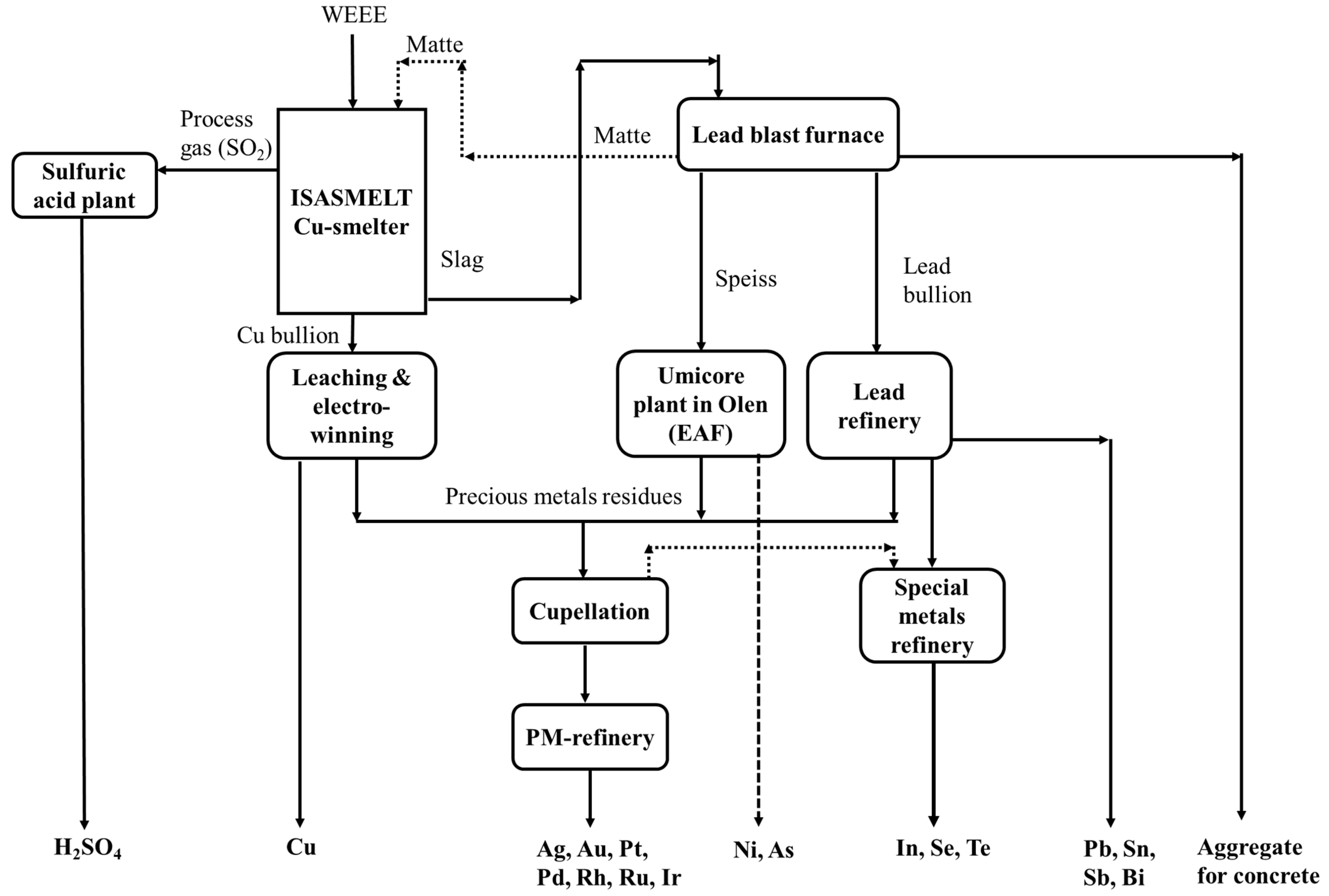
3.5.4. ISASMELT: Secondary Copper Recycling

There are two implementations of ISASMELT furnaces for recycling precious metals and complex copper scrap feeds at Aurubis AG, Lünen, Germany (150,000 tpa, see Figure 14) and Umicore Precious Metals Refining, Hoboken, Belgium (360,000 tpa—see Figure 15). The flowsheet of the ISASMELT at Aurubis AG is shown in Figure 14 and is similar to the Knudsen process mentioned in the previous section and named the “Kayser Recycling System” (KRS). The Aurubis Lünen recycling plant produces copper, precious metals, tin, lead and zinc from copper scrap, electronic scrap and residues. The composition of the feed can be low in copper and precious metal content. Before the TSL smelter process, the aluminum and plastics are separated in the material preparation plant, and the input materials are crushed and treated depending on the chemical composition. Aurubis Lünen is equipped with a 13 m tall TSL unit, the center of the KRS process. The TSL is operated under reducing conditions with the help of heating oil, air and oxygen. The output of the TSL is iron silicate slag with low copper content, a Cu alloy (80 wt.-% of Cu and 20 wt.-% of nickel, tin, lead and precious metals) and zinc flue dust (fumed and collected later and named as “zinc-bearing KRS oxide”). The Cu alloy (black copper) is further processed in TBRC, where Cu content is increased to 95 wt.-%, and tin and lead are “sent” to the slag for further processing in a rotary furnace to produce a Sn-Pb alloy. The copper from TBRC is sent in molten form to the anode furnace. Copper scrap is added to the anode furnace for refining, and 99 wt.-% of pure copper is cast into anode copper. The latter is further refined in the copper tank house to produce >99.995% high-purity copper cathodes. Precious metals such as gold and silver are enriched in anode slimes. Additionally, nickel is extracted as crude nickel sulfate from electrolyte treatment [68].
The process flow of the UPMR, Hoboken, Belgium, is described briefly in the upcoming paragraphs (see Figure 15). Firstly, the complex feed (WEEE and various secondary materials) is shredded into a 7 × 7 mm size, and composition analysis is carried out at UPMR. The shredded material (without sorting any materials) is sent to the TSL Cu smelter, potentially in combination with Cu-Ni concentrates (primary) [61]. The combination of WEEE and Cu-Ni concentrates allows constant TSL feeding and smelting. The reactor uses oxygen-enriched air and fuel for combustion, and coke is added as a reducing agent. Plastics and other organic matter partially substitute the addition of coke and energy supply. Most precious metals report to the copper bullion phase and the rest of the metals to the lead slag phase during processing. The TSL plant off gas contains SO2 (primarily due to Cu-Ni concentrate feed), which is further processed in an acid plant for H2SO4 production. The raw copper, rich in precious metals, is leached and sent to a copper electrowinning plant, where pure copper is recovered. The precious metals are collected as residues during the aforementioned processes, processed during cupellation and within the silver refinery. This leads to the recovery of silver, gold and PGMs (platinum, palladium, rhodium, iridium and ruthenium). The oxidized lead slag from the TSL is processed within a “lead blast furnace”. The lead blast furnace reduces lead slag (i.e., containing PbO) from the TSL, together with additional lead-rich feed (e.g., lead–acid battery-associated feed), into impure lead bullion, nickel speiss, copper matte and slag, the latter being used, e.g., in the cement industry. The copper matte is sent back to the TSL unit. The lead bullion is treated via the Harris process within a lead refinery. Additionally, the nickel speiss is leached to produce nickel sulfate (NiSO4), which is processed at Umicore’s Olen plant [46].
Figure 15. Flowsheet for Umicore’s integrated metals smelter and refinery (redrawn with permission) [46].
Metals 13 01742 g015

3.5.5. Distribution of Minor Elements

In general, some fraction of the minor elements and the bulk of the REEs will report to the slag phase during smelting as oxides. The distribution of elements is influenced by the slag composition, temperature, activities and oxygen partial pressure [69,70]. Their respective reactions can be described as shown in Equation (20) (where M = metal), and their distribution ratios can be described as shown in Equation (21). Further, the distribution coefficient can be represented as shown in Equation (22), where it is evident that it is highly dependent on oxygen partial pressure and activity coefficients of the associated metal and oxide. In addition, this section discusses the distribution of a few elements such as tin, indium, germanium, palladium and tantalum. Finally, the distribution of precious metals and rare earth elements is also touched upon. Mostly, the data presented here have been derived within the context of WEEE recycling and the secondary copper production route (see Table 4); nonetheless, some of the data are associated with the primary production of copper as well.
M + 0.5 × O2 (g) → MOx
L M s / m = ( s l a g   w t . - % ) ( m e t a l   w t . - % )
L m s / m = K n T ɣ M P O 2 x / 2 n T ( ɣ M O x )
where:  L m s / m  = distribution ratio; K = equilibrium constant for the reaction (Equation (20)); nT = total moles of mono-cation species in the relevant phase;  ɣ M  = activity coefficient of M in the metal;  ɣ M O x  = activity coefficient of MOx in the slag;  P O 2 = oxygen partial pressure.

3.5.6. Cobalt Recovery from Slags Associated with Copper and Nickel Processing

Cobalt is a base metal, and due to the growth in the EV industry, cobalt usage is expected to increase (contributing to 57% of consumption). According to [78], in 2020, the world consumption of cobalt was about 120,000 tons and is expected to reach 200,000 tons by 2025 (exhibiting an average increase of 5% since 2013) [79]. Cobalt is largely extracted from Cu-Co (55% in 2020), Ni-Cu-Co-PGM sulfide and Ni-Co laterite deposits (20% in 2020) apart from cobaltite ore (CoAsS). The recycling of cobalt comes from secondary sources, which are mainly battery waste (~55%), tungsten carbide scraps (~20%), super alloy scrap (~10%) and spent cobalt-bearing catalysts (~5%) [80]. The topic of cobalt recovery from slags is hence not only related to the metallurgy of copper but also to the metallurgy of nickel, which is a topic discussed in Section 6 of this review.
The behavior of minor elements within a copper concentrate, such as cobalt and arsenic, has been discussed already in Table 3 for the copper and fayalitic slag system. The occurrence of cobalt resources in the final process’s discard slag from copper and nickel smelting operations has become a common approach for cobalt recovery due to its high demand and metal value. These slag stockpiles (consisting of cobalt) can amount to several hundreds of thousands of tons (e.g., 200,000–500,000 t/y), typically discarded from reverberatory, EF and P-S converters. Cobalt recovery from these discarded slags requires highly reducing atmospheres (lower lance fuel/air ratio in the case of a TSL reactor and the use of typically a carbonaceous reductant, e.g., coal) and higher operating temperatures (1350–1500 °C).
The authors of [81,82] propose two approaches to recover cobalt from the discard slags using TSL reactors:
  • adding a sulfurizing agent and producing a cobalt-containing matte phase (lower grade) at lower temperatures (1300–1350 °C) or
  • producing a (sulfur-deficient) cobalt alloy/matte phase at higher temperatures (1400–1500 °C) without adding a sulfurizing agent.
Considering route “a” (i.e., the addition of sulfurizing agent, e.g., pyrite), it is demonstrated that the use of a pilot-scale TSL can produce a matte containing up to 8 wt.-% cobalt and 10–20 wt.-% sulfur (matte and alloy formation reactions are shown in Equations (23)–(26)). The discardable slag from this process contains less than 0.1 wt.-% Co and 0.1 wt.-% Cu. To maintain lower bath temperatures, sufficient sulfur must be provided to form a purely matte phase; otherwise, a matte/alloy phase is formed due to sulfur deficiency. As a rule-of-thumb, pyrite addition of 20 wt.-% to the slag can be considered a best-case scenario for cobalt recovery. In addition, 9–14 wt.-% of fluxing agents (e.g., limestone, CaCO3) can be added to improve the slag fluidity at the operating temperatures mentioned above.
CoO (slag) + Fe (matte/alloy) → Co (matte/alloy) + FeO (slag)
CoO (slag) + FeS (matte/alloy) → CoS (matte/alloy) + FeO (slag)
NiO (slag) + FeS (matte/alloy) → NiS (matte/alloy) + FeO (slag)
2 CuO (slag) + FeS (matte/alloy) → Cu2S (matte/alloy) + FeO (slag) + 0.5 O2 (gas)
The produced low-grade cobalt matte (8 wt.-% Co and 20 wt.-% S) from the above process is further treated in a converting and a subsequent reduction step. During converting, cobalt would be concentrated in a slag phase; hence, a final reduction step of the converting slag would be required to concentrate cobalt as a metal alloy (exhibiting Co concentration of more than 20 wt.-%) [81].
Alternatively, as discussed by the above authors (concerning route “b”), a single TSL furnace can be used to produce sulfur-deficient matte/alloy (without pyrite addition). However, this operation requires higher temperatures (due to the higher liquidus temperature of the matte/alloy phase). The production of the matte/alloy is justified since Fe and Co are dissolved well within the matte [83]. With the installation of water-cooled copper panels (see Part I of this series of papers), the TSL can be operated in the required 1400–1500 °C range. In conclusion, the TSL can potentially operate using both process routes (as discussed above). Therefore, both low (<0.1 wt.-% cobalt) and high (>0.2 wt.-% cobalt) feed grades can be processed in TSL-based processes. More than 90% recovery from a 1 wt.-% cobalt slag feed to an 8–20 wt.-% cobalt product phase has been demonstrated [81].

4. Lead

4.1. Reactions and Chemistry of Primary Lead and Zinc Systems

The recovery of lead and zinc from primary concentrates is carried out in three stages (see Figure 16). The reactions take place within a temperature range of 1050–1300 °C. During the smelting and reduction stages, the level of metal recovery can be controlled by the oxygen partial pressure in the bath, e.g., by controlling the fuel flow, oxygen-enriched airflow or adding reductants as fluxes. For example, PO2 regulation can occur through the addition of PbS, which in turn can be used to control the level of PbO in the slag [84]. The occurring overall reactions of the three stages (smelting, slag reduction and slag fuming) can be found in [84] and are discussed below, along with respective process engineering aspects [13].
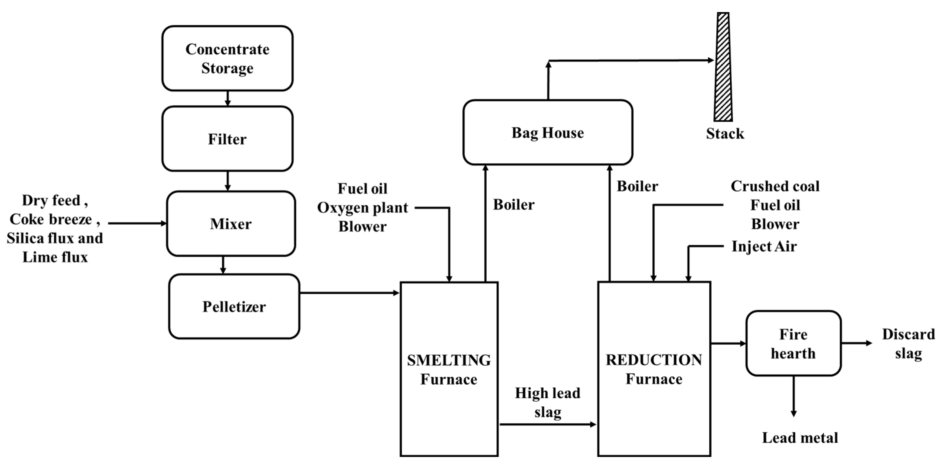
  • Stage 1: Smelting of primary lead concentrates
Lead concentrates are typically sulfidic, and the main lead-containing mineral is galena (PbS) and generally contains significant amounts of ZnS (sphalerite) and pyrite (FeS2). The phase diagram regarding the slag phase during smelting can be found in [13] and is shown in Figure 17. In addition, a respective diagram regarding reduction is available in [74]. Finally, the slag phase diagrams and a description of occurring reactions for all three stages are given in [84].
The smelting stage can be discussed as follows, generally following the discussion within [13]:
  • The silica and limestone act as a flux for slag generation. They are important to keep the slag liquid, considering that lead oxide will be removed within the next phases (PbO removal leads to higher liquidus temperatures).
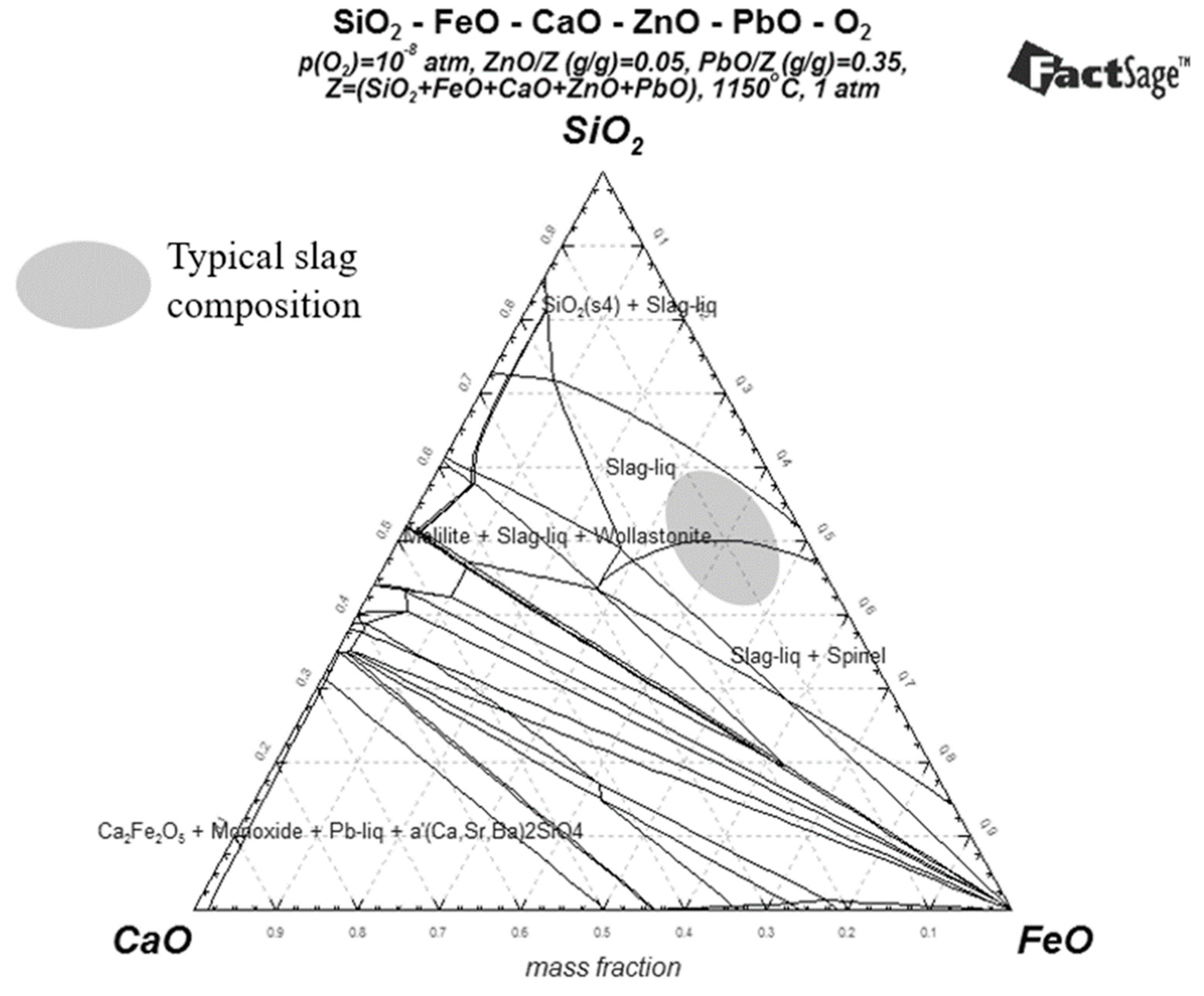
  • The main slag components include FeOx, SiO2 CaO, PbO, ZnO Al2O3, MgO (SiO2/Fe = 0.83–2, for smelting and reducing operations). The content of PbO in the slag is 35 wt.-%. Typical slag chemistry and the operational window (marked region) during smelting are shown in Figure 17. Using our FactSage calculations, the SiO2/Fe values around the center point of the grey circle (in Figure 17) are ~2. The upper and lower points of the circle exhibit SiO2/Fe values of approximately 2.8 and 1, respectively. It should be noted that by adding more SiO2 (i.e., moving to the upper point of the circle), the amount of slag generation will be higher (i.e., more landfill costs and more energy to smelt) and the slag will be more viscous because SiO2 is a network binder.
  • The process is governed by the oxygen partial pressure (10−6.5–10−7.5 atm), which, as discussed above, can be set at will. In stage 1, the goal is to form PbO in the slag by operating the bath under a high partial pressure of oxygen (see Equation (29)). A key aspect is avoiding residual PbS, considering that the latter is a volatile component or can form a matte phase (see Equation (27)). PbS would be stable at a lower partial pressure of oxygen than those mentioned above, which would hinder its oxidation. The importance of oxygen partial pressure is shown since it directly influences reactions 28–37. Hence, the ratios of Pb (bullion)/PbO (slag) or Zn (fume)/ZnO (slag) and Fe+3 (slag)/Fe+2 (slag) and sulfate formation in cooler sections of the off gas path depend on the oxygen potential. Bath oxidation Equations (30)–(33) and (35)–(37) are written as overall equations, while the aspect of oxidation proceeding either through direct oxidation with O2 (gas) or indirectly through Fe3+ is not discussed within the aforementioned reference.
  • Further, the operating strategy involves low temperature (1150 °C) to minimize the vapor pressure of volatile species such as zinc (see, for example, Equation (32)), arsenic and antimony. In addition, the strategy involves keeping the off gas volume low, thus further inhibiting the removal of the above species through fuming.
  • Finally, it is interesting to note that the operating TSL window with regard to the slag (see Figure 17) extends also to a slag–spinel two-phase region with the smelter being able to cope with such a more viscous slag system also due to the inherent aspect of induced turbulence.
PbS (solid) → PbS (fume or to bullion)
PbS (fume or flue dust) + 1.5 O2 (gas) → PbO (flue dust) + SO2 (gas)
PbS (fume or flue dust) + 2 O2 (gas) → PbSO4 (flue dust)
PbS (solid) + 1.5 O2 (gas) → PbO (slag) + SO2 (gas)
PbS (solid) + O2 (gas) → Pb (liquid to bullion) + SO2 (gas)
ZnS (solid) + 1.5 O2 → ZnO (slag) + SO2 (gas)
ZnS (solid) + O2 (gas) → Zn (gas) + SO2 (gas)
Zn (gas) + 0.5 O2 (gas) → ZnO (fume to flue dust or slag)
Pb (liquid) +0.5 O2 (gas) → PbO (slag)
FeS2 (solid) + 2.5 O2 (gas) → FeO (slag) + 2 SO2 (gas)
FeO (slag) + 0.25 O2 (gas) → 0.5 Fe2O3 (slag)
Figure 17. Typical slag phase diagram during the smelting stage showing a complex phase field around the normal operation area (marked as a circle) of an industrial furnace (iron phase is FeOx) (recreated with permission) [74].
Metals 13 01742 g017
  • Stage 2: Reduction of lead from slag
The reduction stage is briefly summarized as follows: [74]
i.
Higher temperatures (~1200 °C) and lower partial pressures of oxygen (PO2 = 10−8–10−8.5 atm).
ii.
It is crucial to minimize zinc fuming to allow direct reuse of the lead-rich fume within the feed (see Figure 16). Zinc fuming can be minimized by:
  • Firstly, reducing the Pb slag content (from 35 wt.-% to approximately 15 wt.-%) by adding PbS (Equation (38)) since the resulting partial pressure of oxygen does not favor zinc fuming.
  • Then, adding carbon (e.g., coal or coke), but still maintaining close control of the oxygen partial pressure. Hence, the goal is to drive Equation (39) forward and avoid reducing zinc oxide and thus fuming zinc. The residual lead content after step 2 is about 5 wt.-%. in the slag. The lab trials using hydrogen as an alternative carbon source are discussed by [85], which is not considered in this report.
PbS (solid) + 2 PbO (slag) → 3 Pb (liquid to bullion or fume) + SO2 (gas)
PbO (slag) + C (solid) → Pb (liquid to bullion or fume) + CO (gas)
FeO1.5 (slag) + 0.5 C (solid) → FeO (slag) + 0.5 CO (gas)
Reactions (38)–(40) represent overall reactions. While direct reduction of PbO and FeO1.5 with carbon is possible, several authors [86,87] postulate a reaction mechanism that involves oxide reduction through CO, thus producing CO2, which in turn reacts with carbon to produce CO again through the Boudouard reaction, thus making the process cyclic. Figure 18 illustrates that lead bullion is the predominant phase at PO2 values mentioned within Figure 16 and at low PSO2 values. This correct prediction is despite the limitations of predominance diagrams when associated with condensed phase processes, e.g., the activity of predominant species being taken as 1.
  • Stage 3: Zinc fuming—slag cleaning
Key aspects of the fuming stage entail [84]:
i.
Increasing temperature to above 1250 °C and decreasing partial pressure to 10−10–10−11 atm.
ii.
The main overall reactions involve volatilization of Zn and Pb, as shown in Equations (41)–(43).
iii.
Zinc and lead are oxidized above the bath to their respective oxides, thus creating dust.
iv.
Fume from the reduction stage is not recycled. Effectively, the fume is a purge for impurities and should be treated separately.
ZnO (slag) + C (solid) → Zn (fume) + CO (gas)
ZnO (slag) + 2 FeO (slag) → Zn (fume) + 2 FeO1.5 (slag)
PbO (slag) + C (solid) → Pb (fume) + CO (gas)
The predominance diagrams for Zn-O-S are shown in Figure 19 and can be used to further elaborate on the aspect of zinc fuming. It is shown in Figure 19 that zinc oxide reduction to a zinc fume is associated with values that are similar to those mentioned above and also noted in Figure 16, i.e., <10−10 atm. The PSO2 is expected to be insignificant as SO2 has already been eliminated in the smelting and reduction stages.

4.2. AUSMELT: Primary Lead Smelting

The three-stage process (smelting, slag reduction and slag fuming) is shown Figure 16. However, the stages applied in practice are mostly smelting and slag reduction, while the fuming stage is only necessary if zinc recovery is required. For plants with a capacity above 100,000 tpa, each stage can be carried out using a single furnace. When smelting and reduction are realized in separate furnaces, higher capacities can be achieved. To demonstrate that different numbers and combinations of furnaces can be used to realize the process of Figure 16, the following plants are discussed: HZL, India (85,000 tpa) processes the feed in one TSL furnace (batch process), YTCL, China (190,000 tpa) utilizes three TSL furnaces (for smelting, reduction and fuming), while Nyrstar, Australia (170,000 tpa) utilizes three furnaces (see Figure 20), where smelting (only) occurs in a TSL furnace, as slag reduction is practiced within the blast furnace followed by a separate slag fumer. The Nyrstar Port Pirie plant flowsheet is shown in Figure 20. The biggest AUSMELT lead smelters are Weser Metall GmbH, Germany (Glencore Nordenham since August 2021) (200,000 tpa) and YTCL (190,000 tpa). Further discussion on the subject is summarized in Table 5 [85]. It should be noted that within this table, several plants are listed that also incorporate secondary materials within their feed mixture. For example, the KCM plant in Plovdiv, Bulgaria produces 70,000 tpa of crude lead (AUSMELT) and 75,000 tpa of zinc alloys and can be found elsewhere in [88].
Table 5. AUSMELT lead processing at different plants (note: if the cells are merged, that means only one TSL is used for respective operations) [89].
IndustryFeed MaterialCapacity (tpa)Mode of OperationProcess
SmeltingSlag ReductionSlag Fuming
YTCL, Datun, ChinaConcentrates190,000BatchAUSMELT
Intertrust Holdings, Olovno Tzinkov, BulgariaConcentrates, battery scrap, residues, slag125,000Continuous, batchAUSMELT (2 TSLs)AUSMELT
HZL, Chanderiya, IndiaConcentrates, sludges85,000BatchAUSMELTImperial smelting furnace (ISF)/slag fumer
Votorantim Metais, Juiz de Fora, BrazilConcentrates, battery scrap, residues75,000BatchAUSMELT-
HCHM, Hulunbeier, ChinaConcentrates, residues66,000BatchAUSMELTSlag fumer
KCM SA, Plovdiv, BulgariaConcentrates, battery paste, slimes75,000BatchAUSMELTSlag fumer
Korea Zinc, Onsan, South KoreaConcentrates secondaries, fume, Pb tailings, leach residues, high-Pb slag>1,000,000ContinuousAUSMELT + QSLAUSMELTsAUSMELTs
Weser Metall GmbH, Nordenham, Germany (Glencore)Concentrates, battery scrap200,000ContinuousAUSMELTSide-blown reactor-
Carat-TSM, Sorsk, RussiaPb polymetallic concentrates170,000ContinuousAUSMELTElectric arc-
Nyrstar, Port Pirie, AustraliaConcentrates, residues170,000ContinuousAUSMELTBlast furnaceSlag fumer
Figure 20. Production process flowsheet of Nyrstar, Port Pirie (world’s largest primary lead-smelting facility) in Port Pirie, Australia (redrawn with permission) [90].
Metals 13 01742 g020

4.3. ISASMELT: Primary Lead Smelting
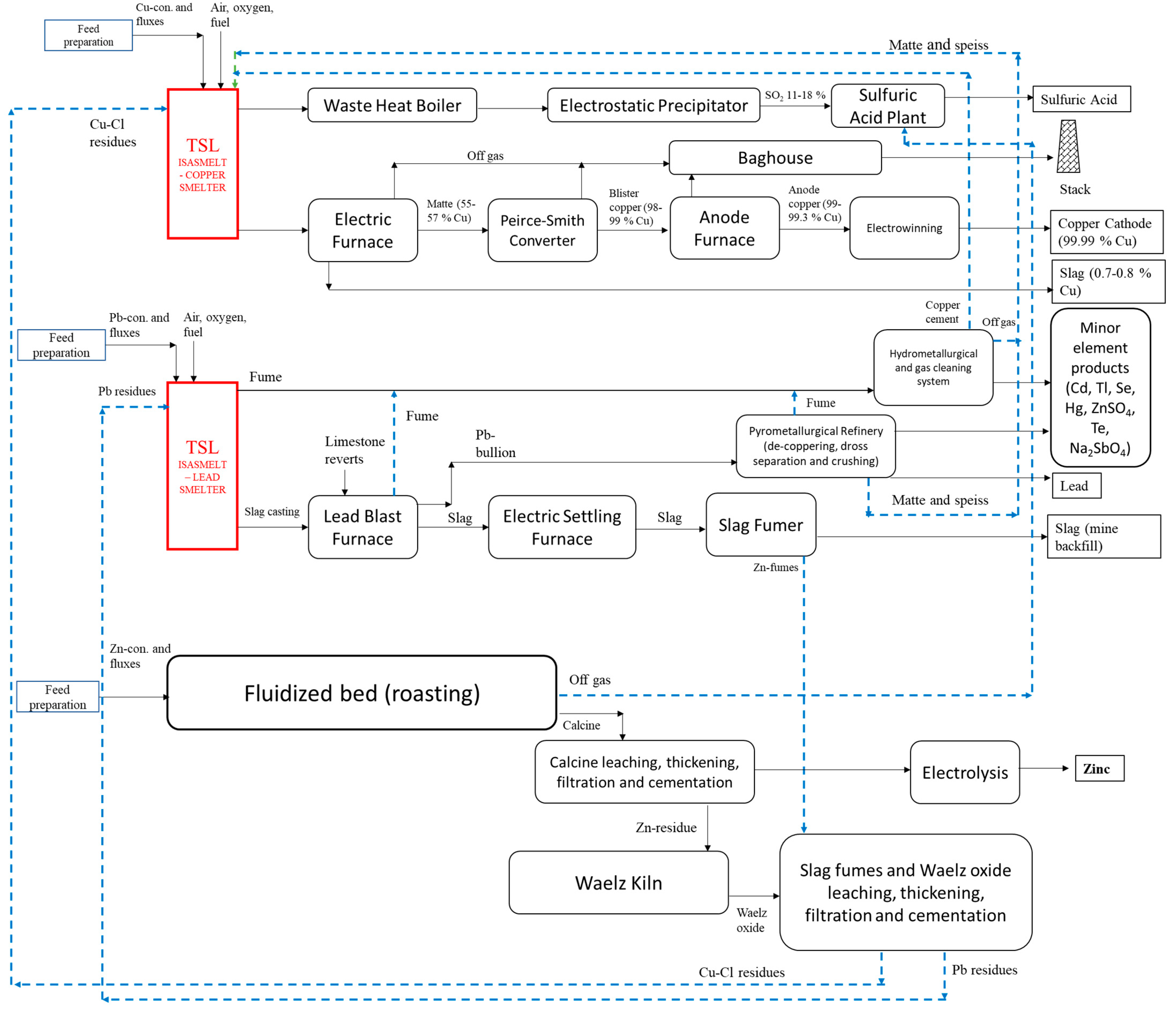
Until 1983, sinter and blast furnace operations were used for lead production at Mount Isa. In 1991, the ISASMELT lead-smelting plant was implemented, and as a result, 210,000 tpa was produced through the combined use of both technologies. The plant flowsheet, corresponding to a 60,000 tpa capacity, is shown below (Figure 21). The plant has two TSL furnaces: the first one is a smelting furnace where concentrates and fluxes are smelted (after mixing and pelletizing) to obtain high-lead slag (50 wt.-% PbO). Then, the slag is transferred to the reduction furnace (second TSL), where it is reduced by crushed coal, and as a result, lead metal and a discard slag are produced. Off gases from both furnaces are cooled down to 200 °C by waste heat boilers, and then they are cleaned by reverse pulse baghouses and sent to the smelter stack. An interesting aspect is mentioned concerning the effect of the concentrate grade within [91]. The plant design was realized for concentrates exhibiting 47 wt.-% Pb. In this case, the lead within the concentrate reports as PbO in the slag directed to the reduction stage, as shown in Figure 21. However, when using high-grade concentrates (e.g., 67 wt.-% Pb), 50% of the incoming lead can be collected as lead bullion from the smelting furnace (not shown in Figure 21). Coke breeze (unsuitable for the blast furnace) was used as fuel in the smelting stage, while a combination of fuel oil and coal fines was utilized in the reduction stage. The presence of zinc oxide in the smelting stage’s slag resulted in zinc ferrite formation on the lance, which acted as a protective coating against slag attack in the smelting stage (see Part I of this series of papers for more information on lance coating through a frozen slag layer) [91].
Another configuration of ISASMELT technology can be observed in YMG, China which has 80,000 tpa feed throughput. The YMG plant consists of an ISASMELT smelting furnace, a YMG-designed blast furnace (for reducing TSL slag), a slag fumer and an electrolytic lead refinery. The ISASMELT furnace effectively replaced the sinter plant. During the smelting step, the sulfur from the lead concentrate feed is oxidized to produce a high-lead slag and off gas rich in sulfur dioxide. The slag is cast and broken into lumps before being fed to a blast furnace to produce lead bullion. In the YMG plant, over 40% of the lead in the feed will report directly to lead metal in the ISASMELT furnace. The ISASMELT lead smelter and YMG-modified blast furnace process is called the “ISA-YMG Lead Smelting Process” [92]. A similar approach can also be observed at Kazzinc JSC, Kazakhstan, commissioned in 2012 with 291,000 tpa feed throughput (shown in Figure 22) [93].
Figure 22 shows only the lead TSL section of Kazzinc Limited and UKMC, Kazakhstan. Although the discussion within this article follows a process-by-process presentation, the plant reality is that of integrated processes, as shown in Figure 23, occurring within the same site. Within the flowsheet of Figure 23:
(i)
a TSL-based copper-concentrate-smelting flowsheet with feed capacity of 294,000 tpa (general aspects discussed in Section 3),
(ii)
a lead TSL flowsheet, with a feed capacity of 291,000 tpa, utilizing a TSL for smelting, a blast furnace for slag reduction and a fumer at the end of the process chain and
(iii)
a zinc extraction flowsheet (from primary concentrates) via RLE including a Waelz kiln for Zn residue fuming are shown.
Hence, this approach allows for streams that cross individual process boundaries to be utilized. For example, copper-containing residues from the lead section are recycled to the copper concentrate TSL smelter. Further, such process integration streams are shown in Figure 23 [94].
Figure 23. Kazzinc-UMKC, Kazakhstan multi-smelter integrated flowsheet (redrawn with permission) [94].
Metals 13 01742 g023

4.4. Reactions of Secondary Lead-Bearing Systems

Co-utilization of secondary materials (e.g., lead–acid batteries) in the process involving lead present in the form of sulfate or oxy-sulfate entails additional reactions. In general, lead from these materials (Equations (44)–(46)) will provide lead oxide (to the slag) and metallic lead that would report to the metal phase (bullion) and, to an extent, to the gas phase [84].
2 PbSO4 (solid) + PbS (solid) → Pb (gas) + 2 PbO (slag) + 3 SO2 (gas)
PbO·PbSO4 (solid) + PbS (solid) → PbO (slag) + 2 Pb (liquid) + 2 SO2 (gas)
PbSO4 (solid) → PbO (slag) + SO2 (gas) + 0.5 O2 (gas)
Reactions (44)–(46) essentially convey that PbSO4 is not stable in conditions prevailing within the smelting stage. Generally, PbSO4 stability requires low temperature and high values of PSO2 and PO2, as can be deduced from Figure 18.

4.5. Secondary Lead Recycling (Lead–Acid Batteries)

Today, most lead is produced from scrap feed, and trends show that secondary lead production will gain importance. Within a 2016 publication [95], the following aspects were reported: secondary lead production exhibited a share of 80% in the United States, 90% in Europe and 95% in countries with low lead resources. The authors further mentioned that the average worldwide share of secondary lead production had been 60–66%. An expected increase in this percentage, with regard to other countries, including China, is linked to the growing electromobility sector. With the increased need for lead–acid batteries, it seems that the lead industry will grow. Secondary lead resources comprise an array of materials, such as lead–acid batteries, pipes, dust, slags and the lead glass associated with LCDs [95].
Nonetheless, lead–acid batteries are the most important secondary resource. About 85% of the lead scrap materials are used for lead–acid battery production [74]. A typical composition of these materials is given in Table 6 [96]. The following sections essentially discuss the recycling of battery paste and grids using the TSL technology.

4.6. AUSMELT: Secondary Lead Recycling

For low-capacity lead-recycling plants (15,000–30,000 tpa), the “AUSMELT-Gravita” processing method potentially replaces the traditional SRF route. The process (not commissioned) operates by realizing smelting and slag-cleaning campaigns (separated timewise). A relatively small slag quantity is produced due to the low levels of gangue materials in battery feeds and associated low fluxing requirements. Typically, the lead batteries contain minimal levels of traditional impurities (e.g., calcium, antimony from the battery grids or silica from glass); see Table 6.
In general, removing plastics and metallic fractions during battery breaking is unnecessary. Nonetheless, doing so would avoid chlorine and fluorine in the casings forming gaseous dioxins. The latter can also be counteracted by cooling the off gas swiftly from 600 °C to 250 °C (see Figure 24). Concerning the fate of sulfur, Figure 24 suggests SO2 capture from the off gas rather than paste desulfurization (discussed within the subsequent section) or capture in a soda–iron slag, typically used for SRFs [89,97].
The flowsheet (Figure 24) shows one TSL furnace used for both continuous smelting and slag-cleaning operations. During the smelting stage (typical slag composition is FeO-SiO2-CaO-PbO), coal is used to ensure mild reducing conditions inside the TSL, thereby producing lead bullion and high-Pb-containing slag (~40 wt.-% Pb, 32 wt.-% FeOx, 23 wt.-% SiO2 and 5 wt.-% CaO at 1150 °C and PO2 = 10−9 atm). The high-Pb-containing slag is stockpiled and later fed to the same TSL together with lump coal fluxes (if required) for the slag-cleaning process. Slag cleaning takes place in two steps: a) the smelting stage slag will be to an extent reduced to produce a minor quantity of bullion that is tapped, and b) the remaining slag is treated with additional lump coal during a highly reductive step, thereby producing a residual slag of 0.5–1.0 wt.-% Pb. The produced slag has been shown to “pass” the TCLP test. Operating at highly reducing conditions during the slag-cleaning stage will result in most lead from the slag reporting to the fume. The slag’s viscosity depends on temperature, slag composition, and lead concentration (i.e., PbO). Higher Pb concentrations in the slag (during smelting) correspond to better slag fluidity and operability. On the other hand, during slag cleaning, the Pb content in the slag decreases, which causes a rise in viscosity. Therefore, appropriate fluxing is required. The off gases before entering the stack are directed to an off-gas-cleaning and SO2 capture section, also removing impurities such as cadmium and arsenic. It is assessed that 96% of the Pb is recovered in the smelting step and 3.9% in the slag-cleaning step; the remaining 0.1% is lost to the final discard slag. It can be observed (Figure 24) that this plant does not have a WHB or acid plant, which is logical considering the small plant scale. Considering that 70% of the operation time would be devoted to the smelting stage and that the bulk of the lead is recovered during that stage, the sale of the low amount of high-lead-content slag after smelting (as a concentrate) can be considered [97].
Figure 24. Process flowsheet for Metso: Outotec AUSMELT-Gravita small-scale lead-smelting process (note: only one TSL is used for smelting and slag-cleaning campaigns) (redrawn with permission) [89].
Metals 13 01742 g024
One of the oldest TSL installations in Europe was commissioned at Weser-Metall GmbH in the year 1996—now “Glencore Nordenham”, Germany (previously owned by Recylex Group and Metaleurop). Before the commissioning of the TSL smelter, the plant was equipped with a sinter and blast furnace. The plant has been reported to produce 105,000 tons of lead annually and is a major lead producer and recycler in Europe. The feed for the TSL is typically 70% secondary lead material (mostly car batteries) and 30% lead primary concentrates. The TSL consists of four input flow paths, taken up from natural gas, air, O2 and O2-enriched air. The operation involves (i) oxide and sulfide smelting (in the TSL furnace) and (ii) subsequent carbothermic reduction (mainly in a side-blown furnace), see Figure 25. The TSL dimensions are about 4.2 m in outer diameter and 9.5 m in height and it is externally cooled by water. The resulting slag freeze lining protects the refractory. The authors of [98] portrayed typical refractory challenges in lead and zinc industries when the slag contains very high amounts of SiO2, sulfur, soda and iron oxide. The protective lance slag coating is noted due to the cooling effect of the air flowing along the outermost lance flow path (see Part I of this series of papers). Lead and slag are removed from the tapholes intermittently (upgraded in 2022 from siphon utilization, see [99]). The SO2-containing off gas is treated to obtain sulfuric acid. The off gas volume at the exit of the TSL is approximated to be 30,000 Nm3/h, at an SO2 strength of 0.5–12% and a temperature level of 1000–1300 °C. The corresponding plant flowsheet is shown in Figure 25 [99,100].
The feed (typically 35–45 tons/hour) in Figure 25 is blended with different concentrates, battery paste, recycled products (dust, refinery intermediates and copper dross) and fluxes. The TSL produces mainly lead-rich slag and lead bullion. The lead-rich slag is sent to a side-blown furnace for reduction. Produced lead bullion from the TSL and side-blown furnace goes through decopperizing, as shown above, and is eventually sent for refining (liquid transport via transport trucks) to further remove impurities. Transferring all materials in liquid form significantly reduces energy consumption and smelting/refining time. A typical smelting stage TSL slag composition is 40–60 wt.-% Pb, 5–15 wt.-% Zn, 10–20 wt.-% SiO2, 5–10 wt.-% CaO and 10–30 wt.-% FeO + Fe2O3. The TSL slag is then sent to a reduction furnace, where the lead from the slag is reduced to a minimum and the left-over slag is granulated and sent to the landfill. The TSL off gas is equipped with a “flux-flow boiler”, which is different from a traditional WHB. A similar flux-flow boiler set-up is also used at the Mount Isa Copper TSL smelter. The heat recovery and hot gas cleaning involve a CFB boiler and two ESPs. The gas is further processed in a wet-gas-cleaning section consisting of a venturi scrubber, gas cooling and wet ESPs leading to the acid plant. Compared with the previous technology at Nordenham, i.e., the sinter and blast furnace, TSL technology application has led to 94–98% emission reduction concerning Pb, Cd, Sb, As, Tl, Hg and SO2. Furthermore, CO2 emissions have been reduced by almost 60% to 0.45 tCO2/tPb. Energy input was reduced by 35%, and water consumption dropped by 3 million m3 per annum. Discharge slag production is reduced when secondary materials are used due to the lower amount of impurities [99,100].

4.7. ISASMELT: Secondary Lead Recycling

Two ISASMELT plants for secondary lead smelting (lead battery scrap) have been built. One of the plants is BRM, UK (commissioned in 1991 with 30,000 tpa), and the other is MRI, Malaysia (commissioned in 2000 with 70,000 tpa). Plant products include low-antimony “soft lead”, lead–antimony alloy “hard lead” and a low-lead iron silicate slag. The BRM plant flowsheet considers sulfur removal by paste desulfurization before smelting, as opposed to sulfur capture, discussed in the previous section [96].
BRM used to refine 10,000 tpa primary lead produced by Mount Isa, Australia, before 1991 and later upgraded the plant and increased the production to 30,000 tpa by producing refined lead and lead in alloys. The flowsheet is shown in Figure 26. The plant upgrade included battery storage, mechanical battery breaking using the Engitec CX process and paste desulfurization as part of the feed preparation circuit for the ISASMELT furnace. Free acid before milling was processed in terms of filtration, neutralization and treatment within an effluent treatment plant. Batteries were fed to a hammer mill. The resulting paste was separated through sieving. Residual materials (metallic lead, case materials and separators) were subjected to “sink/float” operations, allowing components to recover separately. Polypropylene was sold. The battery paste was processed within desulfurization tanks. Respective reactions are shown in Equations (47) and (48). The lead oxide produced was filtered, pressed and fed to the ISASMELT. Grid metal was also smelted, typically in separate campaigns [96,101].
H2SO4 (aq.) + 2 NaOH (aq.) → Na2SO4 (aq.) + 2 H2O (aq.)
PbSO4 (solid) + 2 NaOH (aq.) → Na2SO4 (aq.) + PbO (solid) + H2O (aq.)
The reduction of molten paste occurs by adding a reductant to the paste bath. Conditions are mildly oxidizing, and thereby antimony will mostly report to the slag phase. A lead phase of low antimony (0.01–0.1 wt.-%), also containing some Cu (0.1 wt.-%) forms, is coined as “soft lead”. The soft lead is tapped discontinuously, and hence the slag inventory increases within the TSL. It is then transferred to the kettles in a molten state. The slag’s lead content gradually decreases from 90 wt.-% Pb to a slag where the PbO content is in the range of 55–65 wt.-%. The latter results from the contribution of coal ash components and “paste residuals” (including 10 wt.-% Sb as Sb2O3), which “dilute” the lead content. The mildly oxidizing conditions (i.e., the partial pressure of oxygen) determine the antimony distribution. The slag composition allows an operating temperature of around 810 °C. A further interesting point is the formation of a second slag phase which is lighter than the aforementioned lead-rich (litharge) slag, which contained 35 wt.-% Na as Na2SO4. The source of Na is the paste since it still contained 1.5. wt.-% Na after the desulfurization step. This “lighter” slag was removed through a dedicated upper taphole.
According to the latter reference, the resulting slag was reduced in an SRF along with dross from the kettles [96]. The reduction could have been realized within the TSL [101], the reason being achieving higher productivity. According to [101], which is the oldest reference associated with the BRM plant (which discusses slag reduction within the TSL), the following aspects were noted considering slag reduction: (i) SiO2 and CaO fluxes were added at the end of the smelting stage (fluxes are necessary to maintain slag fluidity after lead removal), (ii) carbon was added to the slag and temperature was raised to 1150–1200 °C, thus initiating the reduction stage of the process, and, (iii) thereby, “hard lead”, which is a lead–antimony alloy, was produced and an iron silicate slag. The typical “hard lead” composition would be 79.2 wt.-% Pb and 20.6 wt.-% Sb and some residual copper while a typical discard slag composition would be 50 wt.-% FeO, 25 wt.-% SiO2, 15 wt.-% CaO, 0.5 wt.-% Pb. The plant operated with air as an oxidant and oil/coal as fuel. Feed rates to the 1.8 m diameter TSL were 12 tph of paste or 35 tph of grid metal. The aggressive nature of lead-rich litharge slag resulted in partial brick repairs after approximately 20,000 t of lead production, while full relining occurred after 70,000 t of lead production.
Figure 26. BRM secondary operations flowsheet (redrawn with permission from The Minerals, Metals & Material Society) [96,101].
Metals 13 01742 g026
The second battery-recycling plant of ISASMELT is MRI, which is slightly bigger than BRM (2.5 m diameter). The operation involves feeding filtered pastes (74 wt.-% Pb, 6.5 wt.-% S, 0.3 wt.-% Sb), grids (92.0 wt.-% Pb, 0.63 wt.-% S, 1.8 wt.-% Sb) and dross. MRI has demonstrated the following features:
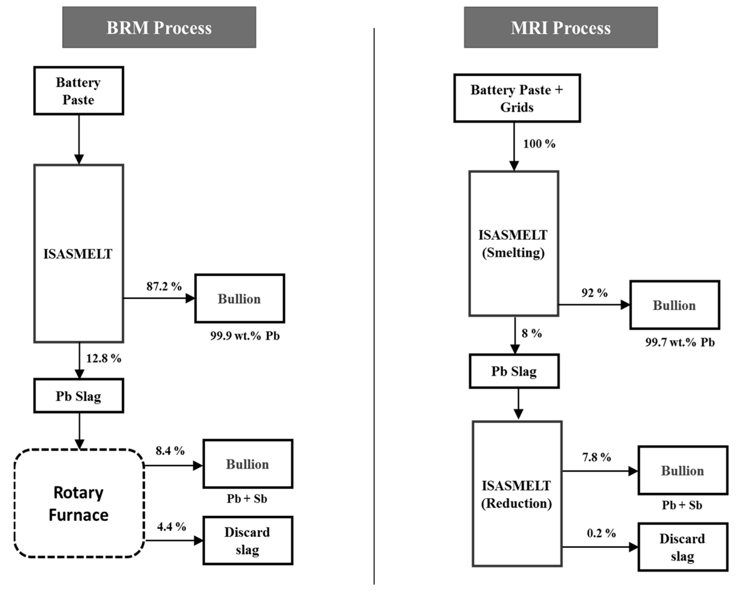
  • Smelting includes feeding a mixture of battery paste, grids and dross.
  • Primary concentrates have also been smelted (up to the limit for SO2 capture) and can be used to partially reduce the high-lead slag, followed by the addition of coal for complete reduction.
  • Natural gas (rather than fuel oil) and oxygen-enriched air are used in the TSL reactor.
  • Sulfur capture is practiced instead of paste desulfurization. The off gases are processed in two stages: the first stage is evaporative cooling followed by bag filters, and the second stage involves SO2 capture. The technology used is named the “Chiyoda Flue Gas Desulfurizer”. The off gas is passed through water, forming a fine bubble bed where SO2 is absorbed, oxidized by injected air and then neutralized by a limestone slurry. This technology provides gypsum to the cement industry.
The operational flowsheet of MRI is shown in Figure 27. The comparison of BRM and MRI with respect to lead distribution is shown in Figure 28. It should be noted that the distribution of lead with regard to the MRI plant refers to the original mode of operation of smelting–stockpiling slag–remelting and finally reducing the lead-rich slag. Later, MRI found this operation mode less economical than performing smelting and slag reduction cycles, thus avoiding slag stockpiling and remelting [96].

Scale-Up Trend

Given the future increase in secondary lead processing requirements and the need to centralize secondary lead production, which will facilitate upholding stricter environmental regulations, a secondary lead TSL furnace can be scaled up to produce over 300,000 tpa of soft lead. A few features of such operation are [96]:
  • Lance air is enriched with 40% O2.
  • A relatively small furnace (3–3.5 m of inner diameter) compared to TSL applications in the primary production sector can be utilized.
  • The smelting stage of the process can be operated continuously, thereby:
    Producing soft lead.
    Producing a SO2-rich gas suitable for sulfuric acid production.
  • Operation at low temperatures of around 850 °C is possible due to the litharge PbO-Sb2O3 slag utilization.
  • Reduction of the produced slag can occur in a second/smaller TSL reactor (approx. 2 m inner diameter).

4.8. Distribution of Indium in Lead Smelters
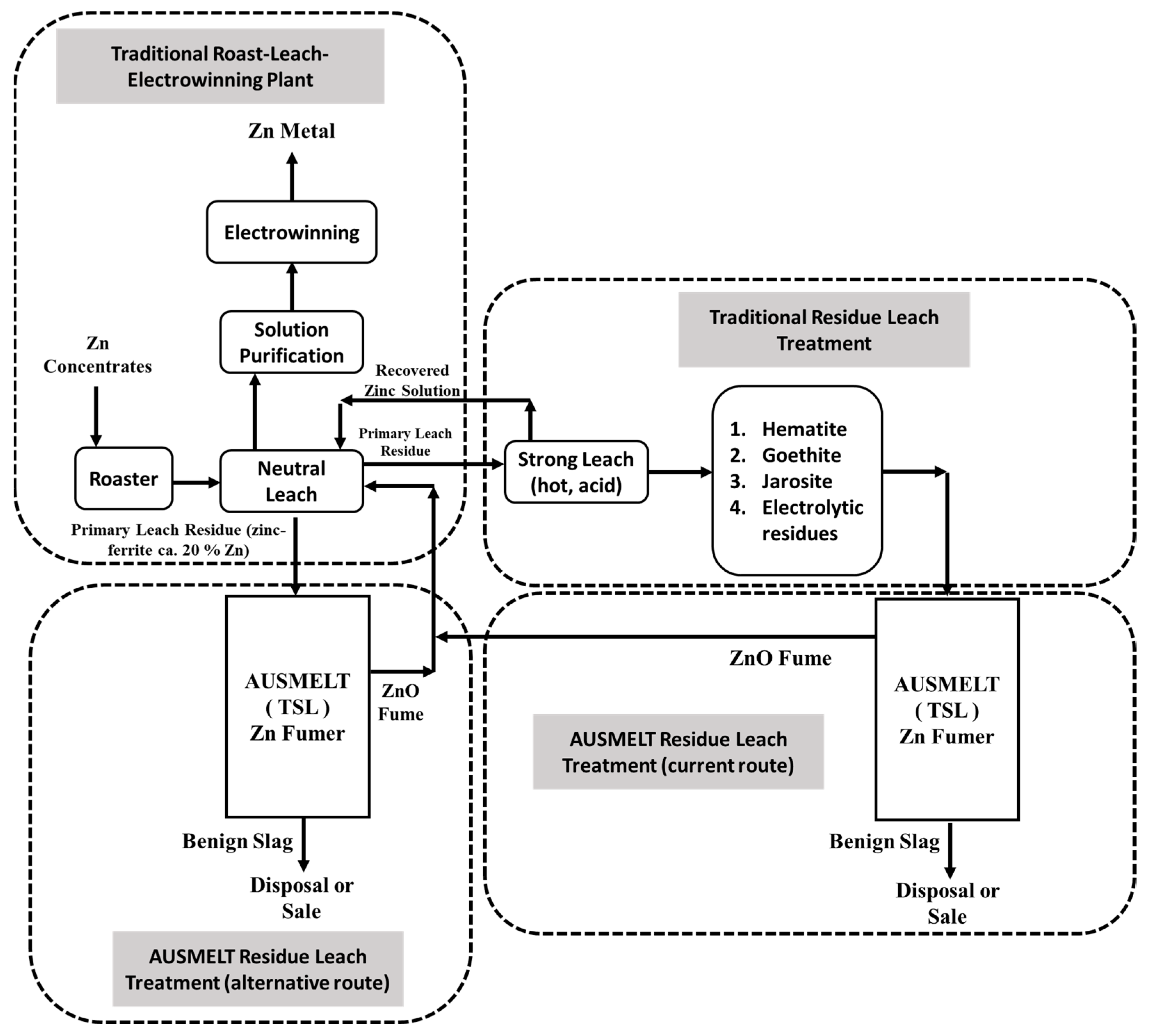
This section can be considered an extension to Table 4, which focused on black copper smelters. The recovery of indium concerning lead smelters is discussed in this paragraph. Indium is found in zinc deposits as a solid solution in sphalerite (ZnS) at 10–20 ppm concentrations. Therefore, indium waste from zinc processing is typically sent to lead smelters. Indium (gas) can be recovered in the zinc-fuming process (i.e., slag-cleaning step in a lead smelter, see Figure 16). The goal is to direct indium to the slag phase (in the 1st and 2nd stage) and then to the fume (in the 3rd stage). For this to occur, the indium should be “carried” within the slag phase in stages 1 (smelting) and 2 (reduction). The distribution coefficient of indium (slag/metal, see Equations (21) and (22)) ranges from 14 to 60, depending on the activity coefficients and prevailing oxygen partial pressures within the system [75], indicating that indium will predominantly report to the slag. Furthermore, the indium distribution in Pb bullion (stages 1 and 2) is discussed in [102], which concludes that it is dependent on the SiO2/Fe ratio and independent of the SiO2/CaO ratio (in FeO-rich slags). In the fuming stage, the goal is to volatilize indium from slag, at 1200–1300 °C, PO2 = 10−9–10−12 atm from an FCS slag system. The indium is therein present as InO1.5 (i.e., In3+), as discussed in [74]. Indium can be fumed as In (g) in the above conditions. Finally, the indium reporting to the Pb bullion (during the smelting and reducing stage) can be recovered using a solvent-extraction-based process discussed elsewhere [103].

5. Zinc

Zinc processing within a TSL unit essentially can be categorized as follows:
  • ▪ Zinc fuming of respective slags, i.e., ISF slag or slags associated with lead, e.g., lead blast furnace slag.
  • ▪ Treatment of EAF dust associated with the secondary production of steel from scrap.
  • ▪ DZS is considered an alternative to classical RLE processes.
  • ▪ Treatment of zinc-containing residues (jarosite, goethite) resulting from the operation of conventional RLE systems (mentioned above).

5.1. Reactions of Zinc System from Experimental Investigations

Zinc fume production may occur through sulfide oxidation (1st stage of the DZS process) or through oxide reduction (reduction of ZnO contained within a slag). Zinc fuming through reduction is relevant to all four aforementioned processes, as discussed in detail in the paragraphs below.

5.1.1. Zinc Fume Production through Sulfide Oxidation (1st Stage of DZS Only)

The following overall reactions (Equations (49) and (50)) will occur only in the 1st stage of direct zinc smelting (DZS).
ZnS (solid) + O2 (gas) → Zn (gas) + SO2 (gas)
ZnS (solid) + 1.5 O2 (gas) →ZnO (slag) + SO2 (gas)

5.1.2. Zinc Fuming (through Oxide Reduction)

Zinc fuming of slags from TSL lead-processing operations has been essentially discussed in Section 4 and is not repeated here. Fuming reactions concerning an oxidic system are given below (Equations (51)–(54)) for zinc. A more detailed analysis of the process is provided in the following sections while discussing associated process variants, i.e., slag fuming, EAF dust smelting, the slag reduction phase of the DZS process and zinc residue treatment.
ZnO (slag) + C (solid) → Zn (gas) + CO (gas)
C (solid) + CO2 (gas) → 2 CO (gas)
ZnO (slag) + CO (gas) → Zn (gas) + CO2 (gas)
Zn (gas) + 0.5 O2 (gas) → ZnO (dust)
The respective temperature is 1150–1300 °C and the partial pressure of oxygen is equal to 10−10 atm. However, most references associated with fuming tend to report operating temperatures at the upper end of this range or even exceeding it (see Figure 16, Figure 29 and Figure 30 and respective references [74,104,105]).

5.1.3. Zinc Slag Fuming

A more in-depth discussion concerning the mechanism of zinc fuming, including associated fluid dynamics, is given below, with the purpose not only of explaining the zinc-fuming process but illustrating the interplay between kinetics and fluid dynamics within a TSL reactor.
Figure 29. Schematic diagram of slag-fuming process from molten slag bath in TSL furnace (redrawn with permission) [104].
Metals 13 01742 g029
Modeling work [86] concerning fuming of an ISF lead blast furnace slag had the following composition: 18 wt.-% ZnO, 45 wt.-% FeO (no Fe3+ considered), 27 wt.-% SiO2 and 10 wt.-% CaO. Process stages involve slag charging, melting, flux addition and, as the last step, reductant addition. The duration of a typical complete cycle is equal to 120–180 min. Figure 30 shows the change in this slag’s composition during the fuming process, resulting in a zinc lean discard slag. Fuel to the furnace was CH4 (natural gas) injected through the lance (entrained coal can also be used), and additional fine coal has been used as the reductant. CH4 combustion with air was modeled to produce a CO/CO2 gas (1:1) analogy and water vapor. A SIROSMELT lance is essentially considered, where CH4 is supplied through the inner pipe, and air passes through the outer annular lance passage, as discussed in Part I of this series of papers. Because of the swirlers used in the lance’s outlet gas passage, O2 (in the air) and CH4 mix well. As a result, 80% of fuel conversion happens in the combustion chamber (i.e., in the elongated part of the outer annular passage compared to the inner pipe) and 20% at the lance tip. The availability of CO at the bath surface (to drive the reduction of ZnO) and the ability to convert produced CO2 to CO through the Boudouard reaction are critical to the process (see Equations (51)–(54)). Based on the above mechanism, the statement that zinc oxide reduction within the slag is controlled by the ZnO mass transfer rate to the gas–slag interface (from the slag bulk) and by the rate of the Boudouard reaction (to produce CO), shown in Equation (52), is justified. Furthermore, the injected gas results in the appearance of recirculation zones, thus enhancing mixing, which should assist ZnO mass transfer to the slag–gas interface. Also, “splashing” has a further positive impact on the zinc-fuming rate and is caused by the turbulence induced through gas injection. Splashing is defined as the “tearing of liquid slag phase”, which causes slag droplets to fly and return to the bath either directly or after impacting the reactor walls. This phenomenon exposes the slag drops to CO-containing gas’s upward movement, and Zn fuming from those drops can again occur through Equation (53). The Boudouard reaction on the bath surface, which provides for the CO mentioned above, is enhanced by “splashing” related drops returning to the bath and by the “sloshing” phenomenon. The sloshing is defined as the wavy/rotational motion of the bath surface also caused due to gas injection, turbulence and the cylindrical shape of the TSL. The relationship between average zinc concentration reduction and time is linear. Average fuming rates are equal to 0.2–0.35 wt.-% Zn/min (for a global temperature of 1227 °C, 18 wt.-% ZnO in the feed slag and with CH4 as fuel and coal as reductant), which are higher than rates for fuming plants utilizing coal as fuel and reductant (0.09–0.27 wt.-% Zn/min for 9–10 wt.-% ZnO in the feed slag) [86].
Figure 30. Typical conditions during the reduction step showing the change in ZnO in slag (arrow) at 1325 °C (recreated with permission) [74].
Metals 13 01742 g030

5.2. AUSMELT: EAF Dust Processing (Smelting and Fuming)

EAF dust/zinc oxide processing to produce a rich zinc fume product and discharge slag has been realized in a pilot-scale AUSMELT furnace. The application, according to the authors [74], is considered attractive since:
  • Lead and zinc contents in the EAF slag are in the range of 15–25 wt.-%.
  • The EAF dust contains heavy metals (such as Pb, Cr, Cd), chlorides and halides, which are leachable.
  • The annual production of the EAF dust was 5 million tpa in 2008.
Today, the bulk of EAF dust processing is realized in Waelz rotary kilns. Independent of the reactor type used, it constitutes a zinc-fuming operation. Within the TSL, direct smelting of EAF dust has been investigated either as a two-stage (smelting/reduction) batch process in one reactor or with the use of a continuous process (with two TSL reactors). In both cases, the goal has been to attain a ZnO fume and a disposable slag of <1 wt.-% Zn. The goal regarding the slag was achieved, while attained fume consisted of 56.7–59.7 wt.-% Zn (70.5–74.3 wt.-% ZnO), Pb (5.3–5.9 wt.-%) and small amounts of entrained iron, silica and CaO. The Cl amounts in the slag and fume were <0.01 wt.-% and <6 wt.-%, respectively. Respective values for F have been <0.5 wt.-% for the slag and approximately 0.5 wt.-% for the fume. Half-time reduction values for zinc from the respective slag are in the range of 25 min [74].
The two-stage batch operation was also employed regarding a combined zinc oxide concentrate and EAF dust feed. Relevant operational parameters were [74]:
  • Smelting stage: Continuous feeding of the mixture above, a temperature of approximately 1300 °C and partial pressure of oxygen corresponding to slag with 3–4 wt.-% zinc.
  • Reduction stage: Stopping feeding of new material, setting a temperature of around 1350 °C, adding coal for 30–45 min to maintain an oxygen partial pressure of 10−10 atm, achievement of a discard slag of below 1 wt.-% zinc, ideally a slag with a residual zinc level of 0.5 wt.-%. The composition of EAF feed dust and products is given in Table 7. Essentially, the phase diagram shown in Figure 30 can be used to describe the above process with regard to the removal of ZnO from the slag phase.
Table 7. Inputs and outputs for direct smelting of EAF dust in AUSMELT [74].
Input
ZnPbFeCuSSiO2CaOMgOMnOAl2O3
EAF dust (trial 1)21.61.329.50.10.55.69.32.72.20.7
EAF dust (trial 2)25.81.924.20.20.5472.52.21
Output
Fume (trial 1)56.25.31--2.40.1---
Slag (trial 1)0.10.05--------
Fume (trial 2)59.25.90.3--1.50.1---
Slag (trial 2)0.70.1--------
A significant aspect of EAF dust processing in the TSL is halides within the fume since the fume will be leached and directed to solution purification and electrowinning. The aspect can be dealt with by water washing of the EAF dust (before feeding to the TSL) and alkali washing of the produced ZnO fume. Alternatives exist in integrating TSL operation with the EZINEX® process (Engitec zinc extraction hydrometallurgical process, which is chloride-based) or ZINCEX™ process, which involves leaching, SX, stripping and electrolysis (used by Skorpion Zinc, Namibia concerning oxidic ore). A final alternative would involve feeding the EAF dust to an AusIron furnace (see Section 8), which would have the additional benefit of producing pig iron [106].

5.3. AUSMELT: Direct Zinc Smelting

The flowsheet of the DZS process is shown in Figure 31. The direct smelting of ZnS is achieved by fuming zinc and its condensation (mainly as ZnO) from a SO2-bearing gas stream, which is utilized to produce sulfuric acid. In the late 1990s, AUSMELT invented a two-stage ZnS-concentrate-smelting–fuming process with BUKA Minerals Ltd. As a result, high zinc oxide levels are recovered in the first stage as fume. In the first stage, zinc is fumed according to Equation (52) or reports to the slag according to Equation (53).
The corresponding slag system is shown in Figure 32 in conditions relevant to stage 1, i.e., smelting at 1250 °C and a partial pressure of oxygen of ~10−8 atm. About 60–65% of zinc is removed through stage 1. Within stage 2, the slag content is reduced from 25 wt.-% zinc to 3 wt.-% zinc. Approximately 40% of the stage 2 slag is recycled to stage 1 to dilute zinc content in stage 1. Dilution in stage 1 is necessary to avoid precipitation (e.g., zincite [(Zn,Mn)O] or willemite [Zn2SiO4]). At the same time, control of the partial pressure of oxygen is necessary to avoid zinc ferrite formation (see Figure 32). Some spinel formation, however, can be tolerated within the TSL operating window due to the turbulent nature of the TSL reactor [74].
The ZnO fume can be processed through alkaline leaching (if required to remove halogens), neutral leaching (pH > 5), solid/liquid separation, purification and electrowinning circuits. The solid residue removed from the aforementioned solid/liquid separation is subjected to weak acid leaching (5–10 g/L H2SO4), neutralization/precipitation and thickening/filtration. Residues are suitable for feeding to a lead smelter. When compared to the state-of-the-art RLE route, this process primarily benefits from a benign slag being produced (that can be used as building material). As a result, environmental concerns and disposal areas (ponds) associated with hydrometallurgical residues such as jarosite or goethite are avoided. Finally, the DZS process may be a more suitable process for concentrates containing elements known to be disturbing in the RLE process, such as Fe, Mn, SiO2, MgO, Ni and Co, which report to the benign slag [74].
Figure 32. The slag phase relationship for direct zinc smelting (stage 1 at 1250 °C) in TSL, showing the slag-liquid area and typical operating point for smelting conditions (recreated with permission) [74].
Metals 13 01742 g032

5.4. AUSMELT: Zinc Residue Fuming

TSL technology can be utilized not only to replace the RLE process but also to optimize it in terms of treating associated residues. The currently practiced route to recover zinc from jarosite (approximately 3 wt.-% Zn) or goethite (approximately 6 wt.-% Zn) represents an additional variant of the zinc-fuming processes, as shown in Figure 33. A prime example is the Onsan smelter of Korea Zinc (flowsheet presented in Part I of this series of papers), which utilizes 12 TSL units, 10 of which are associated with zinc recovery. Feed materials to the fumers involve goethite, Pb residue (tailings) from the zinc plant and slag from the QSL lead smelter. A Zn/Pb fume is produced that is processed in the zinc-leaching plant [107].
Alternatively, the neutral leach residue can be directly used (containing 20 wt.-% zinc as zinc ferrite), as shown in Figure 33. The ZnO fume can be returned to the neutral leach process stage. In the case of feeding the neutral leaching residue to the TSL, the hot acid leaching section is not required (as Zn from zinc ferrite is recovered through fuming). In any TSL processing option for zinc, i.e., the DZS process (presented in the previous section), fuming zinc from goethite or jarosite (after the hot acid leaching section) or fuming zinc from neutral leach residue, a benign slag is produced. In addition, the above fuming processes facilitate the recovery, for example, of indium and germanium. The produced slag from zinc residue is saleable slag with <2 wt.-% Zn, which can be used for construction [107].
Figure 33. Commercialized TSL zinc technology solutions for processing zinc residues (AUSMELT) (redrawn with permission) [107].
Metals 13 01742 g033

5.5. Distribution of Germanium in Lead/Zinc Smelters

In continuation to the discussion within Section 3.5.5. “Distribution of Minor Elements”, this segment addresses the distribution of germanium with respect to lead smelters which also incorporate zinc recovery through fuming (also termed as lead–zinc smelters).
In general, lead concentrates containing zinc and minor elements (e.g., Ge) are sintered and fed to a lead blast furnace and its slag is directed to a slag fumer. In this unit, the zinc is fumed to Zn (gas) and eventually to ZnO (fume), recovered through leaching and finally electrowinning (to produce Zn), as already discussed in the above sections. Considering the above process route (i.e., Pb concentrates with some Zn and Ge and waste material from zinc refineries with some Ge), the Ge goes to the slag phase during the smelting stage in the blast furnace, some volatilizes and a minor amount dissolves into the lead. The product of the blast furnace is lead and slag. The slag contains elements like Zn and Ge, which are volatilized in a slag fumer to form ZnO (fume) and minor fractions of Ge. This fume is acid leached to produce electrolyte for zinc electrowinning. In the zinc electrowinning process, Ge has an adverse effect on reducing the current efficiency and causes multiple pin-holes in cathode deposits even at low concentrations (0.1 ppm) [108]. These adverse effects tend to increase in the presence of cobalt or antimony. Therefore, the presence of Ge, Co and Sb should be minimized in zinc-calcine-leaching operations (i.e., to avoid these elements in zinc electrolyte) by controlling their distribution in metals and slags during the blast furnace and slag fumer operations. The effects above also apply to the TSL lead–zinc-fuming operation. In the context of a lead–zinc smelter, the authors of [108] discussed the Ge distribution by considering CaO-SiO2-FeO-Al2O3 slag at PO2 = 10−12.5–10−10 atm and T = 1150–1250 °C. Under the conditions above, the authors concluded that the Ge is likely to be present in the slag phase as GeO (Ge2+) and its activity coefficient in the slag is in the range of 1.44–2.55. The distribution coefficients of Ge (i.e.,  L G e m / s )  at PO2 of 10−10 atm and 10−12.5 atm are 0.00465 and 0.108, respectively. In addition, if the SiO2/CaO increases, the activity of GeO increases in slag [108].

6. Nickel

The name “nickel” comes from a 15th-century German term “Kupfernickel” or “devil’s copper”, as the ore seemed red-brown like copper and was difficult to mine [109,110]. A growth of 4.7% is expected, leading to a mine production of 4 million tons by 2030 [111]. Laterite ores (reserves equal to 178 million metric tons) and sulfide ores (reserves equal to 118 million metric tons) are utilized, while the use of marine resources, i.e., polymetallic sea nodules, may be considered in the future [112]. The latter are rich in manganese and contain nickel, copper and cobalt; they represent an estimated nickel reserve equal to 290 million tons. Their respective processing is beyond the scope of this review [112]. Approx. 60% of nickel was produced from sulfidic ores in 2011 [113]; however, the situation is changing since the aforementioned increase in mine production comes from laterite ores and is directed to the steel industry (a trend associated with economic activity in China) [111]. Respective products are termed as Class II nickel (nickel pig iron and ferronickel) as opposed to Class I nickel (Ni metal > 98 wt.-% or other chemicals); Class I nickel in combination, termed “mixed hydroxide product, mixed sulfide precipitate and matte intermediates” is used to produce nickel sulfate, e.g., utilized for nickel-containing Li-ion batteries and nickel–cobalt–manganese and nickel–cobalt–aluminum batteries [111]. Hydrometallurgical processes (HPAL and heap leaching [114]) are outside the scope of this article and have been reviewed elsewhere [110]; pyrometallurgical processes are examined to an extent for comparison with TSL-based processing and to highlight common chemistry aspects between them.
Laterite ores are used to produce ferronickel (30 wt.-% Ni and 70 wt.-% Fe), which is directly used, as mentioned, in the steel-making process. Nonetheless, to a lesser extent, nickel laterite ores are also used to produce melting-grade nickel and nickel matte (discussed below). Recently, low-grade laterite ores have been used to produce nickel pig iron in China, the latter being a low-grade ferronickel containing 2–10 wt.-% Ni [115]. The laterite ores are commonly obtained in two forms: saprolite (15 wt.-% Fe), used to produce ferronickel, and limonite/smectite (35 wt.-% Fe), used to generate melting-grade nickel or even matte. Generic formulas for limonite and garnierite can be given as (Fe,Ni)OOH and [Mg[Ni,Co]3Si2O5(OH)4], respectively. The laterite ores are primarily found in warmer climates, e.g., in Indonesia, the Philippines and Cuba, and the sulfidic ores are located in Canada and northern Siberia. On the other hand, sulfidic ores are commonly found in the form of pentlandite [(Fe,Ni)9S8], which is a feedstock for high-grade nickel production. Pentlandites may be nickel-rich (e.g., Fe4Ni5S8 [116]) or iron-rich and may also contain cobalt, (Fe,Ni,Co)9S8 [117]. Other sulfide minerals entail Ni-bearing pyrrhotite [(Ni,Fe)7S8], millerite [NiS], violarite [(Fe,Ni)2S4], polydymite [3NiS.FeS2] and hengleinite [(Ni,Co)3S4]. Both laterites and sulfidic ores contain 1.3% wt.-Ni and 0.1 wt.-% Co; therefore, cobalt extraction from these ores is generally considered (due to the high demand for battery production) [113].

6.1. Reactions in the Nickel System

6.1.1. Nickel Laterite (Saprolite) Ores

Laterites can be processed using two routes: (i) smelting to produce ferronickel or (ii) leaching and refining to make nickel metal. For example, limonite and smectite (high Fe and low MgO) cannot be economically smelted, and saprolite (high MgO and low Fe) cannot be economically leached. Saprolites are generally used to produce ferronickel. Sometimes, saprolite ore is mixed with sulfur and smelted (EAF) to produce matte, producing alloying-grade nickel by oxidation and reductive roasting. Alternatively, this matte can also be processed via hydrometallurgy to produce high-purity nickel and cobalt [113].
The first processing treatment for nickel recovery from laterites was developed in 1879 in New Caledonia, France (overseas), using iron blast furnace technology [118]. The laterite pyrometallurgical flowsheet consists of drying, calcining–reduction, electric furnace smelting and refining. Currently, the primary pyrometallurgical process for treating laterites is the RKEF process, and its disadvantage is high energy consumption. With regard to nickel pig iron, blast furnaces have been used in China, while the use of an EAF has been proposed [115]. A discussion on the RKEF process and its variants are given below so that the respective discussion concerning TSL processing can appropriately follow (in the following sections) [113].
  • Commonly, nickel in the laterite ore is associated with magnesium hydroxy-silicates (e.g., garnierite, (Mg,Ni)3Si2O5(OH)4). The moist laterite ore (1.3–2.5 wt.-% Ni and 35 wt.-% water) is dried/calcined in a rotating dryer/kiln (800 °C) to remove the water content, reduce Fe2O3 to FeO, reduce 25% of NiO to Ni and also reduce 5% of the iron to metallic Fe. Some occurring reactions are given below (see Equations (55)–(60)). Coal is used as the reductant, which explains direct reduction with C and CO, H2 reduction (see Equations (57)–(60)). Drying and partial reduction in the kiln are examples of gas–solid ore processing.
Ni3Mg3Si4O10(OH)8 (solid) → 3 NiO (solid) + 3 MgO (solid) + 4 SiO2 (solid) + 4 H2O (gas)
2 FeOOH (solid) → Fe2O3 (solid) + H2O (gas)
NiO (solid) + C (solid) → Ni (solid) + CO (gas)
NiO (solid) + CO (gas) → Ni (solid) + CO2 (gas)
Fe2O3 (solid) + CO (gas) → 2 FeO (solid) + CO2 (gas)
Fe2O3 (solid) + H2 (gas) → 2 FeO (solid) + H2O (gas)
  • The dry (moisture would cause explosions in the furnace) and hot (900 °C) laterite ore, already containing required carbon from the previous process step, is smelted to form ferronickel (20–40 wt.-% Ni and 60–80 wt.-% Fe) and slag (40–55 wt.-% SiO2, 20–35 wt.-% MgO, 5–20 wt.-% FeO, 1–7 wt.-% CaO and 1–2 wt.-% Al2O3). The slag is classified as an olivine slag, (Mg, Fe)2SiO4. Electric furnaces are typically used for smelting which encompasses suspended electrodes. The reduction to pure nickel (metallic) cannot be obtained because of the low Ni content in laterite (so only Fe-Ni alloy can be produced via saprolite smelting); see Equations (61)–(63). Several slag elements (Ca, Mg, Al, Si) exhibit a higher affinity to oxygen and remain in the slag. Iron distributes between ferronickel and slag. As demonstrated through Equation (64) and Section 3 (however, concerning fayalitic slag), the slag is ionic. Ferronickel and slag temperatures are approximately 1450 °C and 1550 °C, respectively.
NiO (solid) + C (solid) → Ni (liquid) + CO (gas)
FeO (solid) + C (solid) → Fe (liquid) + CO (gas)
Ni (liquid) + Fe (solid) → (Ni, Fe) (liquid)
2   MgO ( solid ) + SiO 2 ( solid ) 2   Mg 2 +   ( molten ionic slag ) + S i O 4 4   ( molten ionic slag )
  • The crude ferronickel from the smelting (contains 0.06 wt.-% P and 0.4 wt.-% S) can be further refined to remove impurities (e.g., S, P, C, Si and O), and later the ferronickel is granulated and sent to steel making (e.g., stainless steel and ferrous alloy making), see Equations (65) and (66). Refining operations occur after tapping within a ladle. Phosphor and sulfur are removed sequentially by adding CaO and CaC2, respectively. It is to be noted that cobalt cannot be removed from ferronickel without significant nickel loss. The chromium, silicon and carbon can be removed through oxidation.
2 [P] (bath) + 2.5 O2 (gas) + 4 CaO (solid) → (CaO)4P2O5 (slag that floats on Fe-Ni and can be removed)
[S] (bath) + CaC2 (solid) → 2 [C] + CaS (slag that floats on Fe-Ni and can be removed)
Most of the laterite ore processing (90%) is carried out as shown above. Still, the remaining 10% is used to produce Ni-Fe-S matte (95–97 wt.-% Ni). The PT INCO, Indonesia process is different in that “liquid sulfur” is added to the laterite during the calcination/reduction process (see Equations (67) and (68)). Hence, approximately 1 wt.-% S is present as a metal sulfide coating within the calcine. This step essentially turns the laterite ores into sulfidic ores; subsequent smelting produces a matte with a significant amount of iron and sulfur. The latter undergoes conversion to create a matte with 75–78 wt.-% Ni and 1 wt.-% Fe. The Le Nickel process (New Caledonia) involves adding sulfur to a P-S converter, thus converting incoming ferronickel to a matte of similar composition [113]. Furthermore, industrial data on nickel laterite processing can be found elsewhere [118].
3 Ni (solid) + 2 S (gas) → Ni3S2 (solid)
Fe (solid) + S (gas) → FeS (solid)

6.1.2. Nickel Sulfidic Ores

As stated earlier, the most common nickel sulfur ore is pentlandite [(Ni,Fe)9S8] [116,117]. Other minerals like pyrrhotite (Fe8S9) and chalcopyrite (CuFeS2) are often found with pentlandite along with gangue rock minerals. Additionally, as noted, cobalt (0.05–0.1 wt.-%) [117] and PGMs (e.g., braggite [(Pt,Pd)S]) also accompany (in a dissolved/distinct form) pentlandite ores. Sulfidic ores can also be processed through the hydrometallurgical route (ammoniacal, sulfate or chloride-based leaching) [113].
The overview of the traditional smelting, converting and refining of sulfidic ores is described below, briefly [113]:
  • The sulfidic ores are crushed and ground before the froth flotation process. Flotation aims to separate gangue and pyrrhotite first (at a pH value of approximately 9). If the copper concentration is high (Cu/Ni > 3), separation of chalcopyrite and pentlandite occurs within a second flotation step (by increasing the pH value to 12). In any case, the nickel sulfide smelting should also deal with a copper content fraction.
  • The Ni concentrate (15 wt.-% Ni and 0.5 wt.-% Co [113] or 40 wt.-% Fe, 3–10 wt.-% Ni, and 1–5% wt.-% Cu [119]) is sent to smelting (to roasting–EAF or to flash smelting or to a TSL reactor), where discharge slag and Ni matte (40 wt.-% Ni, 0.5 wt.-% Co, 25 wt.-% Fe and ~34.5 wt.-% S) are produced at 1350 °C.
  • The primary smelting Ni matte is sent to converting to produce low-iron sulfide matte (50–60 wt.-% Ni, 1 wt.-% Co and 1 wt.-% Fe and up to 23 wt.-% S), termed as “Bessemer matte” at 1275 °C. The latter term refers to a low-iron nickel matte; the threshold regarding iron has been defined as 4 wt.-% [120].
  • The Bessemer matte consists of nickel, sulfur, iron (small amounts), copper, cobalt and PGMs. These elements cannot be separated from molten matte. Therefore, it must be solidified and treated further in two different techniques: vapo-metallurgical (e.g., INCO carbonyl process) or hydrometallurgical refining. When the matte is slowly cooled, heazlewoodite (Ni3S2), chalcocite (Cu2S) and metallic alloy (generated because the original matte is sulfur-deficient) are formed (large individual grains/individual phases), as can be explained from the Ni-Cu-S phase diagram (not shown here). After slow cooling, the matte is crushed and ground so that the grains can be separated. The ground grains are sorted into alloy, copper sulfide and nickel sulfide streams using magnetic separation and froth flotation. It is to be noted that the nickel–copper alloy is magnetic and contains most of the PGMs. The individual recovery of these elements is discussed elsewhere in [113].

6.2. Nickel Smelting

The industrial practices for nickel smelting are discussed herein. Information from [113] is summarized below, with further sources being separately referenced. Information on TSL smelting of nickel sulfide concentrates is discussed alongside the more established variants of roasting–EAF smelting and flash smelting. Furthermore, the industrial data (smelter feed, drying, smelting furnace type and products) of different nickel sulfide smelting plants worldwide have been discussed elsewhere [121].
  • Roasting followed by EAF smelting: The fine nickel concentrate is subjected to oxidation at 650 °C. Because the affinity of oxygen to iron is greater than that of copper or nickel, the primary reaction occurring in the roaster is of the type given in Equation (69). Copper and nickel are sulfidic in the roaster product. The roaster is also fed with a coarse particle flux phase. The bulk of the calcine ore phase is entrained and shows high iron oxidation (40–70% total oxidation degree [113]) during a single pass [119].
    3 Fe7S8 (concentrate, solid) + 38 O2 → 7 Fe3O4 (solid) + 24 SO2 (gas)
    Smelting the calcine in the EAF produces a matte of the following composition: 13–36 wt.-% Ni, 1–13 wt.-% Cu, 0.7–1 wt.-% Cu, 33–53 wt.-% Fe, 17–27 wt.-% S. Nickel is present as Ni3S2 in the matte [122,123] or most likely in sulfur-deficient forms thereof. The recovery of Cu and Ni is 98% to the matte, while Co is 50–80%. Au, Ag and PGMs report to the matte phase [124]. The slag produced has <0.5 wt.-% Ni. The EAF can maintain high temperature levels to cope with potential high amounts of MgO in the slag [113].
b.
Flash smelting: In the flash smelter, roasting and smelting coincide, due to which more nickel is lost to slag because of the highly oxidizing atmosphere. Therefore, flash smelter slag treatment is required by using ESF. The flash smelter’s output is Ni-Fe-S matte (17–47 wt.-% Ni, 1.5–15 wt.-% Cu, 0.4–0.8 wt.-% Co, 20–33 wt.-% Fe, 23–27 wt.-% S) at 1300 °C and iron silicate slag. Matte compositions exhibit less iron; however, more Ni generally reports to the slag, prior to the ESF, the Ni content in the slag being 0.2–4 wt.-% Ni. Recovery of Ni after slag cleaning is 95%, while values from copper and cobalt vary from 80–93% and 26–70%, respectively, i.e., less than the fluidized bed roasting–EAF smelting route [125].
The DON is a variant of the flash smelting process (practiced at Boliden Harjavalta, Finland and Votorantim Metals, Brazil), where high-grade nickel matte is produced continuously using a single flash smelter without a converter. Therefore, typical converter and ladle transportation are eliminated (i.e., with low expenses and emissions). The slag from the flash smelter is further processed in an electric furnace for slag-cleaning operation using coke reduction. The advantage of the DON process over traditional flash smelting is that it can handle high MgO content in the slag. The mechanism of the DON process is to oxidize the feed highly, thereby (i) producing low iron concentrations in the matte, while (ii) the iron oxide produced dilutes the MgO in the slag. The Boliden plant produces matte with 4–6 wt.-% Fe and 70 wt.-% NiCuCo [120,126,127].
c.
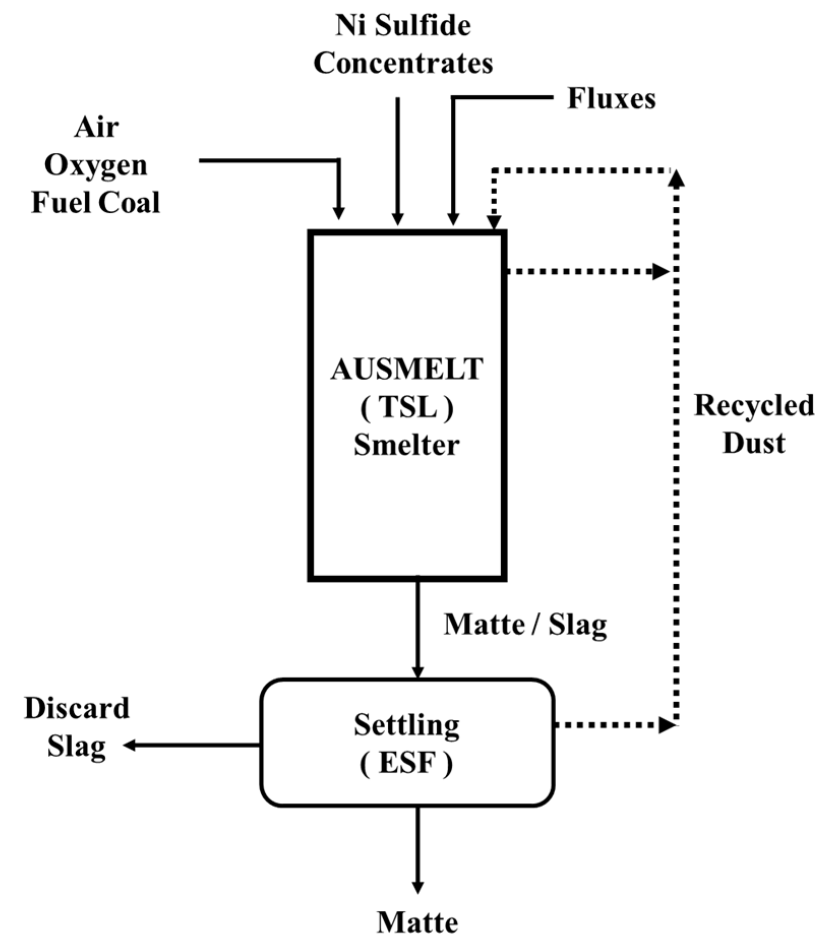
TSL smelting: Similar to traditional nickel smelting, the TSL is fed with nickel sulfide concentrates. The feed dissociates into matte species (e.g., Ni3S2, FeS, Cu2S—see Equations (70)–(73)), which then react with (Fe3+) in the slag to form a primary smelting matte (Fe > 15 wt.-%). The mechanism is similar to that of copper TSL sulfide smelting (see Section 3, Equations (4)–(8) and [14,18]). Suppose the Fe content in the concentrates is low; in that case, Bessemer matte (Fe < 4 wt.-%) can be produced directly from TSL smelting (i.e., without converter) [120]; this represents a TSL variant of the DON process discussed above. Additionally, the authors of [88] portrayed overall reactions (simplified) for a typical nickel–copper concentrate [120] (see Equations (70)–(73)); the latter may also be rich in PGMs (Pt, Pd, Rh, Ru, Ir) and cobalt, gold and silver [113]. The overall reactions (Equations (73)–(76)) project that oxygen directly oxidizes sulfide species instead of Fe+3 oxide species undertaking that role (as discussed in the copper smelting section). Oxygen is supplied in the form of oxygen-enriched air. Based on its affinity to oxygen, FeS reacts to FeO, which reports to the slag. The equations below can be understood as simplifications as they do not capture the sulfur-deficient nature of the produced matte.
3 [(FeS)2. NiS] (concentrate) + O2 (gas) → Ni3S2 (matte) + 6 FeS (matte) + SO2 (gas)
Fe7S6 (concentrate) + 9.5 O2 (gas) → 7 FeO (slag) + 6 SO2 (gas)
FeS (concentrate) + 1.5 O2 (gas) → FeO (slag) + SO2 (gas)
2 CuFeS2 (concentrate) + 4 O2 (gas) → Cu2S (matte) + 2 FeO (slag) + 3 SO2 (gas)

6.3. Nickel Converting

In the traditional converting process, the Ni matte (e.g., from flash smelter/EAF) is oxidized in P-S converters. Exceptions hereto are: (i) Anglo American Platinum, Waterval smelter, Rustenburg, South Africa, which uses TSL continuous converting in the context of the ACP and (ii) Stillwater Mining Company, Montana, USA using two TBRCs in batch mode. As discussed prior, iron and sulfur are oxidized, the first reporting to an iron silicate slag (SiO2/Fe: 0.45–0.5), the latter to SO2, resulting in a reduction of iron to below 4 wt.-% Fe in the product (Bessemer matte). Gold, silver, copper and PGMs follow the matte, while 30–50% of the Co reports to the slag and can be recovered potentially through a carbothermic reduction (see also Section 3), which is typically realized in an electric furnace. Respective reaction equations associated with the oxidation of iron and sulfur (within the converter) are given in Equations (74) and (75) [113].
2 Fe (smelting matte, liquid) + O2 (gas) + SiO2 (flux, solid) → Fe2SiO4 (slag)
S (smelting matte, liquid) + O2 (gas) → SO2 (gas)
The Bessemer matte may be directed to granulation (for subsequent leaching), slow cooling (for flotation to a Ni-, Cu-, PGM-rich concentrate; a requirement being that the residual matte Fe content is <0.5 wt.-%) or anode casting (for nickel recovery through electrorefining, which requires a residual matter Fe content of 0.6 wt.-%). Low iron contents are required to keep contamination of the produced nickel at acceptable levels [113].
The performance of top-blown reactors (as evidenced in the aforementioned plants in South Africa and the USA) is given in conjunction with their preceding smelting process and their overall flowsheet. The feed composition of the Stillwater plant (entering the smelter) is 8–9 wt.-% NiCuCo, 14–16 wt.-% Fe, 11–14 wt.-% S and 10–14 wt.-% MgO. An EAF is used for smelting the feed, where the produced matte composition is 26–30 wt.-% NiCuCo, 40–50 wt.-% Fe and 26–28 wt.-% S. The smelting temperatures were 1400–1550 °C, and the slag composition is 42–48 wt.-% SiO2, 10 wt.-% Fe and 12–16 wt.-% MgO. The EAF matte is granulated and fed to the TBRC, where the converter (Bessemer) matte composition is 75 wt.-% NiCuCo, 2 wt.-% Fe and 20 wt.-% S. The slag composition is 5–7 wt.-% SiO2 (calcium ferrite slag with 20–25 wt.-% CaO) and 45–50 wt.-% Fe [118]. On the other hand, Anglo American Platinum produces 22,000 tpa of nickel (includes Waterval, Union, and Polokwane smelters). The low-Fe Ni-bearing feed exhibits a composition of 5.78 wt.-% NiCuCo, 15.6 wt.-% Fe, 9 wt.-% S and 15 wt.-% MgO. The feed is dried in flash dryers and fed to EAFs operated from 1350–1450 °C (matte temperature range). The smelting matte composition is 26.5 wt.-% NiCuCo, 41 wt.-% Fe and 27 wt.-% S. The slag composition of EAF is 46 wt.-% SiO2, 24.1 wt.-% Fe and 15 wt.-% MgO, while the slag temperature range is 1500–1550 °C. The matte is fed to a TSL for continuous converting (ACP process), and the product converter matte composition is 73.5 wt.-% NiCuCo, 2.9 wt.-% Fe and 21.7 wt.-% S. The converter slag consists of 24–28 wt.-% SiO2 and 42–48 wt.-% Fe. The slag from the TSL reactor is granulated and sent to an EF for further metal recovery. The TSL converter matte is slow-cooled and sent to a base metal refinery. As observed from the above two plants (Anglo American Platinum and Stillwater), the goal of the converting step is to eliminate Fe only as iron silicate (see Equation (74)) or calcium ferrite disposable slag because this is beneficial in the downstream matte refining [121]. The advantages of a TSL furnace over P-S converters are similar to those of other metallurgical processes (e.g., copper processing) and are (i) lower capital and operational costs for off gas collection and cleaning systems, (ii) significant reduction of off gas volume, (iii) provision of constant off gas flow for the SO2 plant and (iv) the TSL can process solid matte as feed material, thereby reducing or eliminating molten ladle transfer (i.e., reducing fugitive emissions and improving plant hygiene) [128,129,130].

6.4. Slag Chemistry during Smelting and Converting

Nickel smelting (ISASMELT) and converting (ISACONVERT) semi-commercial trials were carried out at AGIP Australia Pty Ltd. in 1991 (considering sulfidic feed materials) to understand the system’s thermodynamics. The plant produced 45 wt.-% Ni/Cu matte from a feed containing ~7 wt.-% Ni and ~3.5 wt.-% Cu. The TSL can be operated by continuously feeding the concentrate, fluxes, dust and air/O2 and periodically tapping the slag. The nickel concentrates which were smelted had a wide range of iron contents, from 1.6 to 20 wt.-%. The SiO2/Fe ratio in the TSL reactor slag generated during the tests ranged from 0.7–1.1. The goal of TSL smelting is to produce high-Fe matte (~15 wt.-%) or Bessemer matte (2–4 wt.-% Fe). The composition of the slag is, in general terms: 0.8–7 wt.-% Ni, 0.3–1.5 wt.-% Cu, 0.2–0.3 wt.-% Co, 32–37.6 wt.-% Fe, 25.6–34.9 wt.-% SiO2, 6.7–10.3 wt.-% MgO, 3.8–5.1 wt.-% Al2O3 and 1.4–2.5 wt.-% CaO. The information on the slag liquidus temperatures is calculated to evaluate the phase equilibria in the NiO-MgO-FeO-Fe2O3-SiO2-Al2O3-CaO slag system. The results were calculated at PO2 = 10−7.6 atm, Al2O3 = 4 wt.-%, CaO = 1.5 wt.-% and MgO = 10 wt.-%. Figure 34 shows the operational window, the latter falling within the olivine primary phase field (p.p.f) for a liquid slag [120]. Furthermore, it is important to understand the distribution ratios of Ni and Co in slag in relation to the Fe content in matte. It is concluded that in both nickel TSL smelting and converting operations, if the Fe content in matte decreases, both Ni and Co slag/matte distribution ratios increase. This phenomenon is expected; as the PO2 increases, the Fe levels in matte decrease; however, some Ni and Co will also be oxidized and report to the slag. During TSL nickel sulfide concentrate smelting, the distribution ratios of nickel ( L N i s / m ) and cobalt ( L C o s / m ) increase from (i) 0.02 to 0.06 and (ii) 0.3 to 1.2, respectively, when the Fe content in the matte decreases from 20 wt.-% to 2 wt.-% [120].
As mentioned earlier, the goal of TSL converting is to produce low-Fe Bessemer matte from high-Fe smelting matte feed. The typical TSL converting slag composition is 2.2–6.4 wt.-% Ni, 0.6–1.2 wt.-% Cu, 1.3–2.5 wt.-% Co, 37.8–48 wt.-% Fe and 25.6–34.9 wt.-% SiO2. The bath temperatures are from 1310–1380 °C. As noted above, the Ni level in the slag rises significantly when approaching low-Fe matte compositions. A simplified slag system (NiO-MgO-FeO-Fe2O3-SiO2-Al2O3-CaO), representative of the converting process, at a PO2 of 10−7.6 atm, Al2O3 2.5 wt.-%, CaO 1.5 wt.-% and MgO 2.5 wt.-%, is shown in Figure 35. During the TSL converting process of smelting high-Fe matte feeds, the distribution ratios of nickel ( L N i s / m ) and cobalt ( L C o s / m ) increase from (i) 0.04 to 0.19 and (ii) 0.5 to 2.4, respectively, when the Fe content in the matte decreases from 9 wt.-% to 2 wt.-% [120].
TSL laterite smelting has also been proposed to produce ferronickel alloy from nickel laterite ores (see above sections for general process details), despite the generally elevated temperatures associated with this process due to the presence of MgO in the slag. For pilot trials, the laterite ore composition was 0.3–3.6 wt.-% Ni, 8.4–20.9 wt.-% Fe, 40–46 wt.-% SiO2, 12–22 wt.-% MgO, 0.7–3 wt.-% Al2O3 and 0.2–2.5 wt.-% CaO. The products of TSL smelting were ferronickel alloy (60–85 wt.-% Ni) and a low-nickel slag. The composition of the TSL slag was 18–25 wt.-% Fe, 44–50 wt.-% SiO2, 14–18 wt.-% MgO, 2.6–3.3 wt.-% Al2O3 and 2.8–8.6 wt.-% CaO. A simplified slag system (FeO-Fe2O3-SiO2-Al2O3-CaO-MgO-Cr2O3) was considered to calculate the slag liquidus, and nickel oxide was not considered due to its low-level content in the slag. The phase diagram was calculated for PO2 of 10−11 atm, Al2O3 4 wt.-%, CaO 0.2 wt.-% and Cr2O3 1 wt.-% (see Figure 36). To be noted is the operating temperature of the TSL reactor noted in Figure 36, i.e., in the range of 1500 °C, which is elevated considering the bulk of TSL applications as discussed within this series of articles [120].

6.5. ISASMELT: Primary Nickel Smelting (Laterite)

As discussed in this section, the RKEF is widely used for low-iron, nickel-bearing laterites. An alternative process could be utilized based on TSL technology, where the energy source would be fuel (including coal) oxidation within the furnace. It has been proposed (see Figure 37) that continuous dry laterite feed and recycled dust are fed together with oxygen-enriched air, fuel, coal and fluxes. Although a dryer is included, a calcination furnace (see Equations (55)–(60) above) is optional. Similar to nickel-sulfide-smelting TSL furnaces (discussed in the following passage), the molten bath is tapped from one taphole and sent to a slag-cleaning/settling EF furnace. Additionally, postcombustion inside the TSL furnace (i.e., using extra oxygen supply above the bath) would preheat the feed before entering the bath (i.e., reducing preheating time/step). The slag cleaning/settling EF product is liquid ferronickel and is periodically tapped, which can be granulated, cast or further refined (e.g., to remove S, P, C, Si and O, see Equations (68)–(69)). The slag from the EF furnace can be tapped intermittently and discarded. Should a sulfur-bearing feed material (e.g., concentrate) be added to the furnace, then a nickel matte will be produced (e.g., see Equations (65) and (66)); its subsequent processing would be similar to that of the PT INCO and Le Nickel process mattes. In such a case, an acid plant is added to the heat recovery and gas-cleaning train. It is presumed that considering the high temperatures (1450–1550 °C) and reducing atmospheres, a water-cooled lance design would be required, an aspect that has been discussed in Part I of this series of papers [120].

6.6. ISASMELT: Primary Nickel Smelting (Sulfides)

Nickel smelting (deposits from Mount Isa Mines Ltd., Mount Isa City, QLD, Australia) was one of the early processes (~1980s) carried out. In 1991, a semi-commercial plant (see Figure 38) was built for AGIP Australia Pty Ltd. (now demolished) to produce nickel/copper matte (45 wt.-%) from nickel concentrates (sulfur-based with 7 wt.-% Ni and 3.5 wt.-% Cu). Feed materials including concentrates, fluxes and recycled flue dusts are fed continuously. The liquid matte and slag are tapped periodically from one taphole (batchwise output but continuous feed input). The whole molten bath is directed to a slag-cleaning/settling furnace, and the matte is transferred via ladles to a P-S converter to produce the Bessemer matte. The off gases are sent to a WHB (heat recovery) and ESP (dust recovery) before being sent to wet gas cleaning (not shown) and the sulfuric acid plant. The dust is recycled to the ISASMELT (as already discussed), and the slag is discarded. Additionally, if the feed has low iron content, ISASMELT can directly produce Bessemer matte (<4 wt.-% Fe, without P-S converter use) [120].

6.7. ISACONVERT: Nickel Converting (Sulfide Smelting Matte)

In 2013, Xstrata Technology Pty (now Glencore) patented (US 8,657,916 B2) a pyrometallurgical method including the fluxing composition for continuous smelting and converting of nickel ores [131]. This method encompasses continuously converting low-grade nickel/PGM matte to high-grade Bessemer matte using a calcium ferrite slag system in an ISACONVERT furnace. The trials were conducted for treating PGM matte in a continuous converting process with matte and air/O2 fed continuously to the bath. The respective flowsheet is shown in Figure 39. The granulated smelting furnace matte, limestone, feed, furnace dust, air and oxygen are continuously fed to the TSL, and low-iron Bessemer matte is tapped periodically. The converter slag is tapped through a separate taphole and sent back to the primary smelter. TSL converting avoids a typical P-S converter caveat, i.e., restriction of the converter matte to 2 wt.-% Fe as a result of rapid precipitation of Fe+3 (predominantly as nickel ferrite). Furthermore, in the final blowing step, the P-S converter generates a mush of silica and magnetite-saturated slag entrapped in the final product matte, making phase separation challenging. The better performance of TSL can be explained since, as shown in Table 2, the CF slag exhibits “high solubility for liquid Fe3O4”. The off-gas-cleaning system is similar to ISASMELT (smelting), where the heat, dust and sulfur are recovered [120].

6.8. AUSMELT: Primary Nickel Smelting (Sulfides)

AUSMELT commissioned its first nickel smelter at JNM, China, in 2008, which has a capacity of feed throughput of over 1 million tpa. This technology was named Jinchuan, AUSMELT and ENFI (JAE) nickel smelting technology [133]. The nickel sulfides are fed into the furnace with fluxes and oxygen to control the slag chemistry. The dust from both furnaces is recycled to increase Ni recovery. Fuel and air (enriched with oxygen) are fed with nickel sulfide concentrate to generate the matte rich in a sulfur-deficient form of Ni3S2. The matte and slag are sent to ESF to separate Ni matte and slag (as shown in Figure 40) [88].

6.9. AUSMELT: Nickel Converting (Sulfide Smelting Matte)

The principles of converting nickel matte have been discussed in the sections above. A simplified flowsheet is presented in Figure 41. The flowsheet on the left of this figure corresponds to the Anglo American Platinum converter [88].
Conversely to the CF slag, the continuous ACP uses an iron silicate (fayalitic) slag system similar to P-S converters. The initial flowsheet of ACP involved two-stage batch production of Bessemer matte. In the first stage, the iron in the smelting matte is reduced to ~13 wt.-%, and, in the second stage, it is further reduced to ~3 wt.-%. This two-stage batch process was unsuccessful because of difficulties in determining when to start the second stage of the converting process (unable to monitor the Fe contents in the matte). The batch process resulted in poor/incomplete mixing, non-equilibrium stratification of melts or sometimes rapid mixing of melt layers, which resulted in explosive foaming at low iron-in-matte levels. Therefore, the initial version of ACP is modified to a continuous process, with granulated smelting furnace matte continuously fed to the TSL and converting until the final matte reaches 3 wt.-% Fe. It is to be noted if the converter matte contains < 2 wt.-% Fe, the bath temperatures should be increased substantially to maintain the iron silicate slag fluidity [134]. This challenge could be addressed by using a calcium ferrite slag system (as discussed above) at the cost of increased refractory lining wear (see Table 2).
The overall plant process flowsheet of Anglo American Platinum, Waterval smelter, Rustenburg, South Africa, is presented in Figure 42 in more detail [134]. Firstly, as discussed, for the smelting of nickel sulfide concentrates with high PGMs, an EAF is used. The use of EAF (800 kWh/ton) is necessary because these feeds contain magnesium and chromium, which requires high temperatures to smelt (1600 °C). The objective of smelting is to produce molten matte with high concentrations of PGMs (2000 g/ton). The PGMs have a higher affinity to the matte phase (low affinity to oxygen) and do not report to the slag. The matte is tapped intermittently from a water-cooled taphole and later granulated. The matte (40 wt.-% Fe, 27 wt.-% S and 0.1 wt.-% PGMs) is granulated and directed to the TSL conversion (two TSL converters with 4.5 m inner diameter and 17.5 m height are available on site), where iron and sulfur are oxidized. The goal of TSL converting is to produce converter matte with enriched PGMs (0.25 wt.-% PGM), low iron (0.6–3 wt.-% Fe) and sulfur (20 wt.-% S) contents. Due to the presence of sulfur, Ni and Cu are in sulfur-deficient forms of Ni3S2 and Cu2S, respectively (as stated in the above section). The off gas from the TSL reactor contains the enriched and continuous flow of sulfur dioxide, which is ideal for the sulfuric acid plant. The converting slag from the TSL converter also contains PGMs (minor amount), nickel, copper and cobalt; therefore, a slag-cleaning furnace is required. In this TSL converter, the granulated smelter matte (from the EAF furnace) is fed through the lance (i.e., center pipe, see Part I of this series of papers), together with silica, coal and up to 40% O2 enrichment. Due to the high slag generation in the TSL, the reactor is continuously tapped [88]. The TSL converter matte is slow-cooled and sent to refining. The numbers concerning the Bessemer matte produced with the ACP process are similar between the publications of [88,121,134], mentioned prior in the text.

7. Spent Pot Lining (SPL) Treatment from the Aluminum Industry

SPL is a hazardous waste material of the aluminum industry that should be further treated. Depending on the pot cell’s operational parameters, including online time and type of pot lining used, the spent pot lining contains 38.4–50.2 wt.-% C (graphite), 10.9–18.0 wt.-% fluorides (Na3AlF6, NaF, CaF2), 11.0–13.6 wt.-% Al (Al2O3, NaAl11O17, 1 wt.-% Al), 680–4480 ppm of cyanides (NaCN, NaFe(CN)6, ratio HCN/total 1.9–3.4), 12.5–16.3 wt.-% Na (Na3AlF6, NaF), 1.3–2.4 wt.-% Ca (CaF2), 2.9–4.3 wt.-% Fe (Fe2O3) and minor amounts of Li (Li3AlF6, LiF), Ti (TiB2) and magnesium [135]. The complexity of this feed material is evident. As mentioned by the authors, the material is toxic (leachable in water), corrosive and reactive with water.

7.1. The Chemistry Associated with the SPL Processing

Around 20 tons of SPL are generated for every 1000 tons of Al produced. The goal of the process discussed below is to create a benign slag from SPL and recover fluorine as AlF3. The slag system is complex, consisting of CaO-Al2O3-SiO2-FeOx-MgO-Na2O-NaF [136]. The liquidus temperature is approximately 1175 °C [137]. HF removal is enhanced by injecting steam-containing gas mixtures. A residual content of 3–6 wt.-% F was shown at the lab scale while inhibiting NaF volatilization, as fluorine removal is desired only as HF [137].

7.2. AUSMELT: The ALCOA Portland SPL Processing Plant
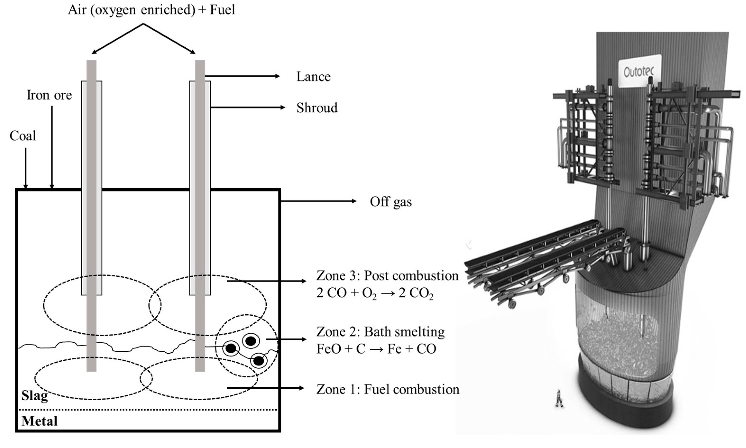
The ALCOA Portland, Australia SPL process flowsheet, of a demonstration processing plant that is no longer operational [135], is given in Figure 43 [138]. The plant started in 1998 and had a capacity of 12,000 tpa of SPL [139]. The slag flux corresponds to a steel-manufacturing electric furnace slag rich in lime, iron and silica [138], while the addition of further silica has been discussed [136]. A key process goal was to increase HF concentration in the gases and utilize this gas to produce AlF3, as mentioned above, which can be reused in the smelter as part of the electrolyte of the Hall–Héroult cell [138,140]. This is achieved through a counter-current gas/smelter-grade alumina (SGA) arrangement. Cyanides and organics were destroyed within the reactor, and carbon was burnt (thus utilizing its thermal energy) [138]. In the flowsheet of Figure 43, the recycling of NaF fines with the use of a baghouse after gas cooling was necessary to promote fluorine removal as HF, while sodium would report to the slag [138]. According to the above authors, granulated vitreous slag was produced with 4 wt.-% F, 13–17 wt.-% Na2O and >25 wt.-% SiO2, which after being subjected to the ASBL procedure, conformed with the Victoria EPA criteria in terms of fluoride leachability (<10 ppm F, which could be decreased up to 2 ppm) [137]. Slag design, which is crucial to fluorine leachability and furnace operation, was aided with the use of thermodynamic modeling (MPE package) [141].

8. Ironmaking

The direct reduction of iron was first tested at CSIRO in the 1960s, and a pilot-test facility was built in Whyalla, Australia (converted to treat zinc residues in 2008, with 55,000 tpa). The process for the production of iron using TSL technology was patented by J.M. Floyd et al. in 1996 (patent number: 5,498,277) and operates with water-cooled lances (1–5 m/sec water flow rate; refer to Part I of this series of papers). The patent illustrates that the direct reduction of iron can be achieved from low-grade or high-grade iron feeds and ferrous scrap. The inventors also discuss that the lance air can be enriched with 40% O2 (or above). Additionally, lump coal and fluxes (such as lime or silica) are added to the TSL during smelting. The process temperatures range from 1350–1500 °C, and high-temperature-resistant lance material is used (such as ASTM 321, 316 or high-chromium steels) together with fluid cooling (see Part I of this series of papers). The TSL design for iron smelting is different in terms of appearance. Due to several lances submerged (typically two), the TSL can take an elliptical shape (see Figure 44: right). Additionally, these lances can operate individually under different lambda conditions. Tapping can occur continuously or batchwise [142,143].

Reactions and Chemistry within the Iron System

Typical iron ores such as magnetite (Fe3O4) and hematite (Fe2O3) contain impurities like sulfur, phosphorous and minor elements that impact the quality of pig iron. The AusIron process has advantages over traditional blast furnaces and EAF, such as a high turndown ratio. For ironmaking, the TSL operates under a more reducing atmosphere than in most non-ferrous metal-processing cases and at higher temperatures. The process mechanism involves a postcombustion process using a shroud lance (see Part I of this series of papers), through which air or oxygen-enriched air is delivered just above the bath. The CO and CnH2n+2 generated during the smelting process are reacted with shroud air. Maximum heat transfer to the melt from the combustion of the species above, while avoiding reoxidization of the bath, can be achieved by controlling the “oxidation degree” of the gas (i.e., [CO2 + H2O]/[CO + H2 + CO2 + H2]). Values of lambda (air–fuel equivalence ratio) 0.95 are set to achieve the above purpose. This technique is also applied to maximize heat recovery within zinc fuming, tin smelting and lead slag reduction (discussed in their respective sections) [142].
The AusIron smelting process, developed by AUSMELT, can be split into three different zones (see Figure 44) [142,144].
  • Zone 1: In this zone, fuel combustion takes place. Fine coal is combusted with less than 60% of the stoichiometric oxygen enrichment.
  • Zone 2: This zone is where the smelting takes place. Iron ore dissolves in the slag bath, and solid carbon (coal) in the bath reduces the dissolved iron oxide into iron metal.
  • Zone 3: This is a postcombustion area (freeboard) where the oxygen is added (via lance shroud) to combust the CO generated through the reduction reactions and the fuel’s incomplete oxidation along with combustion of volatiles emitted by the coal injection. In this zone, combustion heat is transferred to the “splashing” slag, as discussed above.
Concerning the control of impurities, phosphorous and sulfur are discussed herein. By controlling the partial pressure of oxygen (through adjustment of the oxidizing gas and iron oxide flows to the feed rate of coal), the FeO content in the slag can be adjusted so that the equilibrium of Equation (76) can be “pushed” to the right. Increased CaO and MgO levels are favorable for removing phosphorus as P2O5 is an acidic oxide. Hence, by using a basic slag and at a FeO slag level of 15–20 wt.-%, the P content can be reduced to 0.02–0.04 wt.-% in the pig iron, which has been demonstrated through experimentation while using ores with a P content of 0.2 wt.-% (see Equation (76)) [142].
2 P (metal) + 5 FeO (slag) → P2O5 (slag) + 5 Fe (metal)
On the other hand, sulfur enters the system with coal. The following aspects can be noted:
  • Sulfur from the fine coal entering through the lance is mainly converted to SO2 and leaves the system via the off gas.
  • Sulfur entering the system via the lump coal will mainly convert to SO2. This is because lump coal drops in the slag layer and undergoes volatilization (leading to the conversion of iron oxides from the slag and the feed) and does not contact the pig iron.
  • Increasing slag basicity increases the capacity of the slag for sulfur.
As a result of the above, pig iron at the Dandenong pilot plant was produced with < 0.02% of S, even when utilizing coals with 0.3–1 wt.-% sulfur. Nonetheless, sulfur removal to the slag is favored at low FeO contents in the slag. This is in contrast with the higher FeO contents in the slag, which are required to remove phosphorus. In other words, the partial pressure of oxygen and lance lambda values that are optimal for sulfur and phosphorus removal are different. In a two-lance TSL reactor, this is solved by operating one lance under more oxidizing conditions (more FeO in the slag), thus removing phosphorus from the pig iron and the other lance under more reducing conditions (less FeO in the slag), thereby more sulfur reports to the slag. According to the authors, slag should be tapped from the more reducing side and iron from the more oxidizing side, leading to maximum iron recovery in the pig iron phase, characterized by a low amount of impurities and a dissolved carbon content of 3–4 wt.-%. The latter is characteristic of higher-grade pig iron [142].

9. Municipal Waste Processing

According to the World Bank, in 2018, about 2.01 billion MT of MSW was generated, and it could increase to 3.40 billion MT by the year 2050. Currently, only 13.5% of MSW is recycled, and 5.5% is composted [145]. Due to the global population growth and improved lifestyles, efficient recycling technologies for MSW are needed. Currently, MSW recycling occurs in two steps: (i) sorting (separation of plastics, paper, glass, etc.) and (ii) energy generation from MSW residue. This section’s content focuses on MSW-to-energy conversion technologies (i.e., using incinerators). The incinerators for MSW convert the waste into residues, bottom ash and fly ash or create a slag. All the products may be processed further downstream for maximum recovery of materials and energy. A few types of incinerators available in the market are moving grate, rotary kilns, fluidized bed, electric arc furnace, plasma furnace, induction furnace and coke-bed furnace. A TSL furnace can also be considered. The downstream process depends on the incinerator’s product; a few examples include hydrometallurgical steps for metal recovery such as leaching, dilution and solvent extraction, while ash smelting is discussed below (using TSL). The process chain of different technologies can be found in [146,147,148].

9.1. Reactions and Chemistry Associated with MSW Processing

In 1994, J.M. Floyd and B. W. Lightfoot patented [149] (US patent number: 5,615,626) that TSL can be used for processing MSW, industrial wastes (e.g., rubber and plastics) and hospital wastes. In the patent, the inventors illustrate that the MSW can be fed to the TSL without sorting because the temperatures in the TSL are higher (i.e., 1000–1400 °C) compared to moving grate or rotary kilns (i.e., 600–1000 °C). The high temperatures in the TSL can be used to burn organic and inorganic components to form gas species (CO, H2, H2O, SO2, H2S, HCl, HF and NOx) and metal oxides, i.e., a slag phase. The organic substances will generate heat and save fuel costs (see Equations (77)–(79)). As the TSL can handle the off gas well, the toxic volatile gases (e.g., furans, dioxins by rapid cooling) can be safely processed, i.e., through scrubbing or filtration. Later, the off gases are passed through filtration (e.g., electrostatic precipitators or baghouse) to remove fumed particles (such as PbO, ZnO, As2O3, Sb2O3 and any carbon soot). After filtration, the gases are sent to scrubbing, where acids like HF, HCl, SO2, NOx and SO3 are removed. If any unburnt hydrocarbons evolve above the slag bath, postcombustion is preferred using a separate lance or by a lance shroud so that they are oxidized and provide better heat transfer to the slag bath (see Part I of this series of papers and also the previous section) [149].
C + O2 → CO2
2 CO + O2 → 2 CO2
CH4 + 2 O2 → CO2 + 2 H2O
As in a typical TSL furnace, the waste can be fed by a feed port or lance. The fuel can be natural gas, coal or fuel oil, oxidized by air enriched with O2. The lance is water-cooled as the slag temperatures can reach 1800 °C, because of combustible materials in the MSW (e.g., plastics), although it is preferred to run the TSL reactor at 1000–1400 °C. To counteract excessive temperature, the following can be implemented [149]:
  • The heat energy can be extracted from the TSL reactor by a water-cooled or steam-cooled heat exchanger (adjustable, i.e., lower or higher) coupled to the TSL smelter.
  • Water can be sprayed on the external steel casing of the TSL.
  • Low-energy MSW feed, stockpile slag or flux can be added to the furnace.
  • The lance can be protected by extensive water cooling and selecting high-temperature-resistant materials.
It is to be noted that, initially, the TSL reactor is fed with the synthetic slag and smelted before the MSW is fed. The slag chosen can be silica-based, containing oxides like lime, sodium oxide, potassium oxide, iron oxide, alumina, magnesia and manganese oxide. The metal fractions from the waste will be captured in the slag or during off gas treatment. For example, volatile metals or oxides such as Pb, Sb, As, Cd and Zn (few fractions) may report to the off gas and will be present to an extent as dust/fly ash. On the other hand, non-volatile metals such as Fe, Al, Zn (the remaining fractions) will report to the slag in oxide form due to the prevailing oxidizing conditions. The slag (containing metal fractions) can be further processed or granulated and used for building material or to reduce the excessive heat in the TSL (as discussed in the earlier paragraphs) [149].
The TSL can be operated in one of the following ways:
  • Batchwise: A fixed amount of waste is fed into the furnace successively and treated until the slag bath reaches the tapholes. Thereby, the same bath height is achieved after every cycle.
  • Continuous: Waste can be fed and simultaneously tapped.
  • Semi-continuous: The waste can be fed continuously, but the slag is tapped intermittently.

9.2. AUSMELT: Ash Processing/Smelting

Although the TSL has been considered as an incinerator, see aforementioned patent [149], no industrial reference exists to date. Only one TSL was installed in 2005 in Mapo, Seoul, South Korea, to treat boiler/bottom ash from the existing rotary kiln (as shown in Figure 45). At Mapo, the TSL reactor is fed with incinerator ash and separate iron scrap with an annual throughput of 10,000 tons. It is a relatively small TSL furnace (inner diameter ~2.4 m) compared to other TSL installations, which processes primary, secondary and recycling feeds. The Mapo TSL reactor operates with natural gas and produces zinc fume as output (final product). About 500 kg of ash is mixed with water in a mill to agglomerate, then fed into the TSL reactor through a rotary feeder. The lance (oxygen-enriched air and fuel) generates turbulence in the TSL furnace, and the temperature is set around 1230 °C. The waste is smelted for 6 h, in which 85 kg of steel swarf (scrap), most likely acting as a reducing agent, and 20 kg of lime are fed into the TSL as flux. The gases that emerge because of smelting are exposed to a postcombustion in the reactor space above the slag bath section (by shroud). The produced off gas is cooled by evaporative cooling until the gases reach 150 °C. The produced water effluent consists of a condensation of all fume and other condensable species. The off gas is further treated via a bag filter and wet scrubber before being integrated with the gas-cleaning system of the main MSW incinerator plant, as shown in Figure 45. As the TSL was installed later at the Mapo facility (with respect to the MSW plant), the off gas heat is not recovered due to the inability to integrate this heat source with the steam cycle of the main incinerator. Finally, 530 kg of slag and 14 kg of zinc fume are generated considering the above-mentioned feed materials. Eventually, the slag is used as a building material, thus utilizing the ash “waste stream”. Alternatively, the slag can be used for landfill disposal. There is limited available information about the TSL operation, detailed slag chemistry and final product composition of the Mapo facility [140,150].

10. Simulation and Digitalization concerning the TSL Technology

To conclude this series of papers, it is noteworthy to mention that considerable simulation work has been carried out over the decades to understand the TSL mechanisms with respect to lance and bath dynamics. A detailed analysis is beyond the scope of this paper. A review article [151] focused on simulation aspects of the TSL was published in 2022. A few of these models were also validated by lab-scale TSL experimentation. For example, different types of bubble regimes were presented in [152,153,154]; lance injection dynamics with respect to viscous fluids and wall effects were investigated by [155]; experimental investigations to determine the bath velocities, mixing and turbulence phenomena with swirl and non-swirl flows were portrayed by [156]. The latest articles [157,158] show CFD simulations of Top Submerged Lance hydrodynamics of different viscous liquids, i.e., the relationship between bubble dynamics (sphericality, mixing time and surface area) and influencing parameters (surface tension, density, viscosity, flow rate and lance immersion depth). The articles above conclude that the bubble dynamics are highly dependent on viscosity (i.e., to a large extent, bath temperature) and surface tension, which influences the reaction kinetics within the TSL. Experimental investigations using acoustics, motion sensors and collecting real-time data are described by [159,160,161] and feeding such data to CFD models, AI and ML could represent a promising way forward towards digitalization. As noted, the latter models are generally coupled with real-time plant measurements, are predictive and can be used to advise the operator. At the same time, such systems can overtake part of the actions that would be generally associated with operator handling. Hence, plant operation, including dynamic aspects, can be accounted for. Respective platforms have been discussed in Part I of this series of papers. The goal is to achieve a more sustainable process by improving the plant’s overall efficiency with minimum energy consumption, emissions and losses. The authors of [162] discussed possible methods and solutions towards achieving “net-zero” emissions when utilizing TSL technology. Generally, the decrease in the “cost” of using such tools, often termed “digital twins”, has been considered to be in the range of 3–10%, which is significant [163].

11. Conclusions and Summary

The TSL furnace has become an industry workhorse based on its inherent attributes and operational flexibility, thereby becoming indispensable in the quest for smelting and refining of metals from primary and secondary resources. Its applications considering copper and PGM recycling (black copper smelting) from WEEE, lead production through battery recycling and zinc recovery from residual streams such as slags render it crucial in the context of coming closer to the ideal of a circular economy. Its more niche applications described here, such as the processing of spent SPL or utilization in the field of municipal solid waste processing, underline this fact. However, as demonstrated in detail, the TSL reactor is also at the center of primary production and is indispensable with regard to tin, copper and lead concentrate processing. Although furnace selection is a case-by-case exercise when designing a flowsheet, the TSL furnace can outperform alternative options due to aspects such as the inherent possibility to mix solid or gaseous reductants well with the slag system of interest (see the case of TSL tin slag reduction in comparison to the same process carried out in a reverberatory furnace). A further key attribute is the ability of the TSL furnace to remove elements through fuming, which is utilized for metal recovery (e.g., tin, zinc and lead) in several flowsheets or for impurity removal (e.g., arsenic or antimony) in the case of primary copper production.
Fluid dynamics attributes, in other words, the contacting of involved phases, i.e., gas, slag, matte or molten metal, influence the metallurgical process outcome significantly. Hence, TSL processing exhibits distinct features:
(i)
inducing turbulence as a result of blowing gas to a molten bath (slag),
(ii)
regulating the oxygen potential both by controlling the flows of oxidants (oxygen-enriched air, oxidic concentrates) or reductants (such as carbonaceous fuel or sulfidic concentrates fed through the lance or overhead),
(iii)
indirectly oxidizing, e.g., concentrate or matte species, by use of Fe3+ oxides within the slag phase,
(iv)
reoxidizing Fe+2 back to Fe+3 by gaseous oxygen conveyed through the lance,
(v)
being able to set different oxygen potentials within the bath and above the bath (use of shroud air to oxidize reducing gases), while simultaneously allowing for respective recovery of the generated heat through falling “splashing” droplets and
(vi)
low amounts of dust make it a versatile reactor option from a metallurgical standpoint.
This paper revisits the fundamentals to facilitate holistic application understanding, especially as far as process realization, occurring reactions, phase diagrams (especially those associated with the slag phase) and distribution coefficients between phases are concerned. Envisaged or built flowsheets have been analyzed, thus providing a complete view of TSL processing. Specific process design aspects associated with AUSMELT or ISASMELT plants have been considered throughout the review; thereby, these are not repeated here. However, some overarching features of the examined metallurgical applications are summarized below.
Two main aspects where the TSL reactor has aided tin metallurgy can explain the prominent position of the TSL reactor within respective processing methods. Firstly, the practice of solidifying the slag from the first reduction stage (that produces crude tin, >96 wt.-% Sn) to mix it with a carbonaceous reductant and then remelt the slag (to carry out the second reduction stage that produces a hardhead tin–iron alloy), a practice typical for reverberatory furnaces, can be avoided. This is true since solid reductants can be mixed in with the molten slag due to the turbulence within the TSL reactor instead of “floating” on top of the bath and because gaseous reductants can also be used. In addition, a low tin oxide concentration (1–2 wt.-% Sn as SnO) in the discard slag can be achieved because of the rapid coalescence of the produced metal phase. The aforementioned reduction stages can be realized in a single TSL reactor, thus avoiding both cooling/remelting and fugitive emissions. With a sulfurizing agent, slag fuming can recover tin as SnS, later oxidized to SnO2 that is then fed to the reduction stage.
When considering the primary metallurgy of copper, specifically matte smelting and converting, the oxidation mechanism (involving the Fe+2–Fe+3 cycle, discussed above) is specific to the TSL reactor since oxidant gas is blown in a fayalitic slag. Thereby, the activity of Fe+3 in the slag is important. In practical terms, the content of magnetite should be above 5 wt.-%; otherwise, matte species oxidation will be hindered. Therefore, the SiO2/Fe ratio is controlled for that purpose (in the range of 0.6–0.9) since too-low values potentially lead to solid magnetite formation. At the same time, too-high values disturb the reaction mechanism, i.e., the aforementioned Fe+2–Fe+3 cycle. The slag produced within a TSL copper smelter reactor is low in copper (an iron silicate slag system with ~0.6 wt.-% Cu) since overoxidation to Cu2O is avoided. A further reason is that typical matte grades in a TSL reactor are moderate, i.e., up to 65 wt.-% Cu. Due to the above, only ESF or RHF furnaces are utilized for phase (matte/slag) disengagement, and a slag-cleaning furnace is not required. Typical operating conditions involve a temperature below 1190 °C and partial pressure of oxygen of 10−8.4 atm. The low specific dust formation (below 1% compared to the feed rate), associated with the ability to feed low-moisture coarse material to the TSL, may provide means to remove impurities such as arsenic and antimony that form volatile compounds. While oxygen enrichment rates up to 80% and fine/dry concentrate feed through the lance may improve the CO2 footprint, they may have an adverse effect on impurity removal through the gas phase. In any case, TSL smelting is a competitive technology to the more established flash smelting technology and other tuyere-based smelting aggregates. Regarding matte converting, a significant number of investigations have focused on continuous converting, although batch converting in a separate TSL can lead to the substitution of several P-S converters and is more widely practiced. In the continuous converting context, the discussion has focused on the slag choice on the one hand (fayalitic, FCS, CF) and the relationship of residual sulfur in the blister copper vs. the copper oxide reporting to the converter slag on the other. While fayalitic slags are standard for copper processing, their solubility regarding Fe3O4 is limited. Hence, for continuous converting, FCS and CF slags are considered, the latter exhibiting the highest solubility concerning Fe3O4 but being most aggressive towards the refractory lining. Continuous converting, involving continuous granulated matte feed, has been shown at an industrial scale within a TSL to produce a blister copper of 0.3 wt.-% residual sulfur, while the Cu2O in the slag was equal to 18 wt.-%. Continuous converting offers the additional advantage of a continuous SO2 flow to the acid plant.
The attributes of TSL smelters being able to handle bulk feed through overhead feeding, their inherent turbulence and the ability to control the operating oxygen potential are valued in “black copper” smelters handling partly oxidized and alloyed feed materials. These can be classified as metallurgical, industrial and consumer wastes, including WEEE. Respective flowsheets involve a two-step process where a low oxygen potential step is followed by an increased oxygen potential step or vice versa. Black copper (up to 80 wt.-% Cu) is always an internal process stream, while raw copper and discharge slag are produced in the highest and lowest oxygen potential, respectively. Cases where the TSL reactor is used as the 1st reduction stage followed by P-S or TBRC or where both reduction stages are carried out in a TSL unit have been conceived. Of particular interest is the treatment of fumes to recover, among other elements, tin, zinc and lead. The produced raw copper has been either refined to anode copper and copper cathodes via electrorefining (NiSO4 recovered by electrolyte purification and PMs through the refining of the slimes) or by leaching. In the latter case, copper is produced by electrowinning while the leaching residue is electrolytically treated to recover PMs. The distribution of elements between metal and slag phases has been central to lab-scale investigations, using equilibration furnaces, considering the complexity and diversity of the feed materials entering black copper smelters. The behavior of tin, indium, tantalum, germanium, palladium, gold and gallium has been investigated. Temperature, partial pressure of oxygen and slag/metal alloy phase composition (defining respective activity coefficients) influence element distribution between the phases. PMs/PGMs and REEs represent extreme cases, reporting primarily to the metal/alloy phase and slag phase, respectively. Finally, cobalt recovery from copper or nickel slags can also be realized within a TSL reactor when applying reducing conditions. The Co-rich intermediate products are a cobalt-containing matte or a cobalt alloy/matte phase, depending on the addition of a sulfurizing agent, such as pyrite.
The processing of galena (PbS) concentrates involves three stages (smelting–reduction–fuming) characterized by increasing temperature (from min. 1100 °C to max. 1350 °C) and lowering the partial pressure of oxygen (from max. 10−6.5 atm to min. 10−11 atm). Additionally, regarding the ability of the TSL reactor to control the PO2 closely, the turbulence in the bath provides for close temperature control. During the smelting stage, the turbulence within the reactor allows for tolerating some solid magnetite formation, while a zinc ferrite coating protects the lance. Eliminating PbS to PbO (within the slag) or Pb (bullion) is important to avoid lead volatilization and matte phase formation. Within the second stage (reduction), the partial pressure of oxygen is controlled to allow the reduction of lead but not of zinc (to not contaminate produced fume) and maximize lead bullion formation. This is achieved by the sequential addition of PbS and a carbonaceous fuel as a reductant. Fuming (third process stage), realized at maximized temperature and minimized partial pressure of oxygen, is only implemented if zinc recovery is intended. This step produces zinc- and lead-containing fumes requiring separate treatment. The above three-stage process has been implemented in batch mode (within a single TSL reactor) or in continuous mode (using three individual TSL units). Furthermore, TSL smelters have been combined with other aggregates, such as a blast furnace for the PbO-rich slag reduction followed by a separate slag fumer.
Nonetheless, lead scrap, especially lead–acid batteries, is the most important lead resource (grids contain metallic lead, and battery paste contains PbO2 and PbSO4; grids and battery paste are recovered upstream of the smelting process). Therefore, lead recycling from batteries has been combined with the above-mentioned process for primary concentrates within its smelting (first) stage, the secondary material being the feed bulk. Comparing this TSL-based process with the sinter and blast furnace alternative, TSL-based processing significantly reduces energy input, CO2 emissions and pollutants as demonstrated industrially. Separate secondary material processing also makes sense since it contains far less gangue-related impurities than concentrates. Also, battery paste and grids have been treated separately or in combination. Sulfur contained within the battery paste is handled either by paste desulfurization prior to pyrometallurgical processing or through SO2 capture after paste smelting. The molten paste is first treated in relatively oxidizing conditions and at a low temperature (around 810 °C, which is possible due to the absence of gangue material), producing (i) “soft lead”, containing little antimony and copper and (ii) a lead, antimony-rich litharge slag (PbO-Sb2O3). The latter is further reduced to a tin–lead alloy “hard lead” and an iron silicate slag (<0.5 wt.-% Pb). The aforementioned two reduction steps can be realized in one reactor or within two in-series reactors. A future TSL reactor flowsheet may involve 300,000 tpa of “soft lead” using two TSL reactors.
Zinc is relevant to TSL processing in the context of fuming. It has been considered concerning lead smelter slag fuming, EAF dust treatment from secondary steel production, the DZS process and the treatment of zinc-containing residues from the RLE process such as jarosite and goethite. Zinc fuming occurs at low partial pressures of oxygen (10−10 atm) and at temperatures often higher than 1300 °C. The corresponding reduction (reaction) mechanism, discussed in the context of slag fuming, is of general validity for reduction processes being carried out in the TSL reactor. Hence, the availability of CO at the bath surface and the mass transfer of the slag oxide of interest (in this case zin oxide) to the bath surface (from the slag bulk) are of critical importance to the reaction rate, the latter being the rate-controlling step. Produced CO2, occurring as a product of the reduction reaction, is regenerated to CO via the Boudouard reaction. Transferring zinc oxide to the bath surface and exposing the bath surface to reducing (CO-containing gas) is aided due to turbulence-induced phenomena in the TSL reactor, i.e., the appearance of slag circulation zones and splashing/sloshing phenomena. Producing zinc oxide fume through EAF dust also has to cope with halides that report to the fume. Respective processes have been developed to allow zinc electrowinning from a sulfate or chloride solution. In addition, the DZS process has been introduced as a further two-stage smelting–reduction process (followed by hydrometallurgical treatment of the fume to produce electrolytic zinc) that could replace the RLE process. Alternatively, fuming to recover zinc has been applied, as mentioned, to jarosite (3 wt.-% Zn) and goethite (6 wt.-% Zn), which are RLE process residues. A further process variant is to treat the residue of the RLE process after neutral leaching. In any of the process options discussed, the slag produced is low in zinc (<2 wt.-% Zn) and is benign and saleable.
TSL smelting has been applied industrially for sulfidic nickel ores. The process bears similarities to copper concentrate smelting, for example, concerning the indirect oxidation of concentrate and matte species by Fe+3 oxides within the slag and the reoxidation of Fe+2 to Fe+3 by gaseous oxygen. The production of Bessemer matte (<4 wt.-% Fe) can be attained in one step with a low iron-containing feed blend in the smelter (similarly to the flash smelting DON process). Continuous converting has been demonstrated using a calcium ferrite slag and avoiding precipitation of Fe+3 as nickel ferrite. Industrial application of continuous converting using an iron silicate slag has been realized, leading to a Bessemer matte of approx. 2.9 wt.-%, with it being noted that reducing iron content to below 2 wt.-% would require a significant temperature increase to maintain slag fluidity. TSL processing has been extended to laterite feed materials to produce ferronickel or a matte phase by adding a sulfurizing agent. Nonetheless, this process has not seen industrial application, potentially due to the higher temperatures required considering the presence of magnesium and chrome oxide in the laterite feed and resulting slag, leading to slag liquidus temperatures potentially higher than 1500 °C.
Niche applications of TSL processing involve ironmaking and waste stream processing, including SPL and MSW (including related ash). Ironmaking requires a fluid-cooled, heat-resistant lance. It is a more challenging process from a lance stability perspective, considering higher process temperatures (1350–1500 °C) and lower oxygen partial pressures than other non-ferrous TSL applications. Heat recovery to the bath occurs via adding overbed shroud air. Simultaneous sulfur and phosphorus removal from the pig iron is achieved by operating an oval-shaped two-lance system, where the lances induce different oxygen potentials. SPL processing involves converting this toxic and fluoride-rich waste stream of aluminum production to a benign slag (CaO-Al2O3-SiO2-FeOx-MgO-Na2O-NaF), where fluorine is present as sodium fluoride. The rest of the fluoride is recovered as aluminum fluoride after being volatilized as hydrofluoric acid. Finally, although the TSL reactor had been conceived as an MSW incinerator, it has been utilized to treat bottom and boiler ash from an MSW plant (in the context of a fuming process), while using steel swarf as a reducing agent to produce a benign slag that can be used as construction material and a zinc fume.
Despite the multitude of industrial applications associated with the TSL reactor demonstrated above, the fundamental principles and models within industrial and pilot-scale TSL furnaces are not well established. Therefore, in situ measurements and validated CFD models should be further developed to optimize the furnace operation. It should also be noted that the TSL reactors have some challenges, which are handling large off gas volumes (due to moist feed throughput), usage of fossil fuels for heat and mass transfer and lance and refractory wear due to aggressive bath splashing. In conclusion, with the TSL flexibility and efficiency for processing primary feeds and secondary materials, the efficient handling of off gases (e.g., constant SO2 production) and the limited amount of flue dust generation (i.e., surrounding the reactor), it is expected that the TSL reactor will see further application for established and novel processes being developed.

Author Contributions

A.K.: conceptualization, methodology, literature survey, investigation, visualization and writing—original draft preparation. M.A.R.: supervision, formal analysis and resources. M.S.: supervision, formal analysis and validation. M.R.: supervision, project administration and funding acquisition. M.G. and A.R.: supervision and reviewing. A.C.: supervision, resources and writing—reviewing and editing. All authors have read and agreed to the published version of the manuscript.

Funding

The authors would like to thank the funding agency–BMBF, Germany–for supporting the research done at TUBAF, Germany, within the framework of the CIC-Virtuhcon (Grant numbers: 03Z22FN11 and 03Z22FN12) between the years 2015 to 2022.

Acknowledgments

The authors would like to thank Glencore Technology, Australia (S. Nikolic, B. Hogg, M. Prince), Metso, Australia (R. Matusewicz, J. Hoang, D. Wilson), P. Voigt (Redwood Materials, USA) and M. Bakker (Pyrometallurgy Specialist, Australia) for providing information on TSL technology as well as valuable comments and suggestions about this document. We thank C. Zschiesche, Glencore Nordenham for supporting the lead author (A. Kandalam) to complete and submit this series of articles during his full-time work in the industry.

Conflicts of Interest

Markus A. Reuter has a patent on Top Submerged Injection Lances (US 9528766) issued to Outotec Oyj. Markus A. Reuter has a patent on Lances for Top Submerged Injection (US 9771627) issued to Outotec Oyj. Markus A. Reuter has a patent on Fluid Cooled Lances for Top Submerged Injection issued to Outotec Oyj. Markus A. Reuter was previously employed by Outotec (AUSMELT) Australia and Finland (2006–2015). Alexandros Charitos was employed by Outotec GmbH & Co. KG in Germany from 2011–2018 in the field of fluidized bed roasting technology. Avinash Kandalam started working full-time as a Process Engineer at Glencore Nordenham in March 2022. The authors have undertaken every effort to provide an unbiased review.

Nomenclature

Acronyms
ACPAnglo Platinum Converting Process
AIArtificial Intelligence
ASBLAustralia Standard Bottle Leaching
ATSAssociated Tin Smelters, Australia
BFBlast Furnace
BMBFBundesministerium für Bildung und Forschung (the German Federal Ministry of Education and Research)
BRMBritannia Refinery Metals
BZPBuka Zinc Process
C3 ProcessMetso’s 3-stage Converting Process
CFCalcium Ferrite
CFBCirculating Fluidized Bed
CFDComputational Fluid Dynamics
CIC-VirtuhconCentre for Innovation and Competence—Virtual High-Temperature Conversion
CSIROCommonwealth Scientific and Industrial Research Organization
DONDirect Outokumpu Nickel
DRCDemocratic Republic of Congo
DZSDirect Zinc Smelting
EAFElectric Arc Furnace
EFElectric Furnace
EPAEnvironmental Protection Authority
E-scrapElectronic Scrap
ESFElectric Settling Furnace
ESPElectrostatic Precipitator
EVElectric Vehicle
FCSFerrous Calcium Silicate
FQMFirst Quantum Minerals
GRMGlobal Resource and Materials
HCHMHulunbeier Chihong Mining Limited
HFOHeavy Fuel Oil
HPALHigh-Pressure Acid Leaching
HZLHindustan Zinc Limited
ICSGInternational Copper Study Group
ISFImperial Smelting Furnace
ITOIndium Tin Oxide
JNMJinchuan Nonferrous Metals
KRSKayser Recycling System
LCDLiquid Crystal Display
MIMMount Isa Mines
MLMachine Learning
MPEMulti-Phase Equilibrium
MRIMetal Reclamation Industries Sdn. Bhd.
MSWMunicipal Solid Waste
MTMetric Tons
PGMPlatinum Group Metal
PMPrecious Metal
P-SPeirce–Smith
QSLQueneau–Schuhmann–Lurgi
REERare Earth Element
RHFRotary Holding Furnace
RKEFRotary Kiln–Electric Furnace
RLERoasting–Leaching–Electrowinning
SGASmelter-Grade Alumina
SPLSpent Pot Lining
SRFShort Rotary Furnace
SXSolvent Extraction
TBRCTop Blown Rotary Converter
TCLPToxicity Characteristic Leaching Procedure
tpaTons Per Annum
tphTons Per Hour
TSLTop Submerged Lance
TUBAFTechnische Universität Bergakademie Freiberg
UKMCUst-Kamenogorsk Metallurgical Complex
UNUnited Nations
UPMRUmicore Precious Metals Refinery
WEEEWaste from Electrical and Electronic Equipment
WHBWaste Heat Boiler
wt.-%Weight Percentage
YCCYuan Copper Cooperation
YMGYunnan Metallurgical Group
YTCLYunnan Tin Corporation Limited
ZTSZhong Tio Shan

References

  1. Hagelüken, C.; Lee-Shin, J.U.; Carpentier, A.; Heron, C. The EU Circular Economy and Its Relevance to Metal Recycling. Recycling 2016, 1, 242–253. [Google Scholar] [CrossRef]
  2. Giurco, D.; Littleboy, A.; Boyle, T.; Fyfe, J.; White, S. Circular economy: Questions for responsible minerals, additive manufacturing and recycling of metals. Resources 2014, 3, 432–453. [Google Scholar] [CrossRef]
  3. Jackson, M.; Lederwasch, A.; Giurco, D. Transitions in theory and practice: Managing metals in the circular economy. Resources 2014, 3, 516–543. [Google Scholar] [CrossRef]
  4. Reuter, M.A. Digitalizing the circular economy: Circular Economy Engineering Defined by the Metallurgical Internet of Things. Metall. Mater. Trans. B 2016, 47, 3194–3220. [Google Scholar] [CrossRef]
  5. Reuter, M.A.; van Schaik, A.; Gutzmer, J.; Bartie, N.; Abadías-Llamas, A. Challenges of the circular economy: A material, metallurgical, and product design perspective. Annu. Rev. Mater. Res. 2019, 49, 253–274. [Google Scholar] [CrossRef]
  6. Brown, A.G. Alluvial Geoarchaeology; Cambridge University Press: Cambridge, UK, 1997; ISBN 052156820X. [Google Scholar]
  7. Ross, B.; Alexander, G. Estaño, xi and tin 43 years (and counting) of TSL smelting. In Proceedings of the High Temperature Processing Symposium, Melbourne, Australia, 3–4 February 2014; Swinburne Institute of Technology: Melbourne, Australia, 2014. [Google Scholar]
  8. Floyd, J.M. Recovery of Tin from Slags. U.S. Patent 3,905,807, 16 September 1975. [Google Scholar]
  9. Floyd, J.M.; Jones, K.W.; Denholm, W.T.; Taylor, R.N.; McClelland, R.A.; O’Shea, J. Large scale development of submerged lancing Sirosmelt tin processes at associated tin smelters. In Proceedings of the AusIMM-Symposium on Extractive Metallurgy, Melbourne, Australia, 12–14 November 1984. [Google Scholar]
  10. Floyd, J.M. Submerged smelting of tin slags-a new approach to lower-grade concentrate smelting. In Proceedings of the 4th World Conference on Tin, Kuala Lumpur, Malaysia; 1974. [Google Scholar]
  11. International Tin Association. Outotec to deliver AUSMELT from TIMAH. Available online: https://www.internationaltin.org/outotec-to-deliver-ausmelt-for-timah/ (accessed on 21 September 2020).
  12. Wood, J.; Wilson, D.; Hughes, S. A New Era in Smelting Sustainability—Intensification of the Outotec® Ausmelt Top Sub-merged Lance (TSL) Process for Zinc Production. In Proceedings of the PbZn 2020: 9th International Symposium on Lead and Zinc Processing, San Diego, CA, USA, 23–27 February 2020; Springer: San Diego, CA, USA, 2020; pp. 63–73. [Google Scholar] [CrossRef]
  13. Gu, H.; Song, X.; Lan, X.; Baldock, R.; Andrews, R.; Reuter, M.A. Design and commissioning of the Ausmelt TSL lead smelter at Yunnan Tin Company Limited. In Proceedings of the International Smelting Technology Symposium: Incorporating the 6th Advances in Sulfide Smelting Symposium, TMS, Florida, FL, USA, 11–15 March 2012. [Google Scholar]
  14. Shamsuddin, M.; Sohn, H.Y. Constitutive topics in physical chemistry of high-temperature nonferrous metallurgy—A review: Part 1. Sulfide roasting and smelting. JOM 2019, 71, 3253–3265. [Google Scholar] [CrossRef]
  15. Davenport, W.G.; King, M.; Schlesinger, M.E.; Biswas, A.K. Extractive Metallurgy of Copper; Elsevier: Amsterdam, The Netherlands, 2002; ISBN 0080531520. [Google Scholar]
  16. Schlesinger, M.E.; Sole, K.C.; Davenport, W.G.; Alvear, G.R.F. Extractive Metallurgy of Copper; Elsevier: Amsterdam, The Netherlands, 2021; ISBN 0128219033. [Google Scholar]
  17. Kemori, N.; Denholm, W.T.; Kurokawa, H. Reaction mechanism in a copper flash smelting furnace. Metall. Mater. Trans. B 1989, 20, 327–336. [Google Scholar] [CrossRef]
  18. Hogg, B.; Nikolic, S.; Voigt, P.; Telford, P. ISASMELT™ technology for sulfide smelting. In Proceedings of the Extraction, MetSoc, CIM, Sudbury, ON, Canada, 26–29 August 2018. [Google Scholar]
  19. Alvear, G.R.F.; Arthur, P.; Partington, P. Feasibility and profitability with copper ISASMELT. In Proceedings of the International Copper Conference, GDMB, Hamburg, Germany, 6–10 June 2010. [Google Scholar]
  20. Robilliard, K.R.; Short, W.E.; Guorgi, G.A.; Baldock, B.R. Ausmelt’s Top Submerged Lance technology applied to copper smelting. Min. Lat. Am./Minería Latinoam. 1994, 411–421. [Google Scholar] [CrossRef]
  21. Mariscal, L.; Herrera, E. ISASMELT TM slag chemistry and copper losses in the rotary holding furnaces slag at Ilo smelter. In Proceedings of the 8th International Conference on Molten Slags, Fluxes & Salts, Santiago de, Chile, Chile, 18–21 January 2009. [Google Scholar]
  22. Mounsey, E.N.; Li, H.; Floyd, J.W. The design of the Ausmelt Technology smelter at Zhong Tiao Shan’s Houma smelter, People’s Republic of China. In Proceedings of the TMS, Phoenix, AZ, USA, 10–13 October 1999. [Google Scholar]
  23. Jun, W.; Yi, L.; Baizhi, C.; Swayn, G.P.; Wood, J.T.; Creedy, S.J. Design and commissioning of an Outotec Ausmelt copper smelter for Daye non-ferrous metals company LTD. In Proceedings of the Cu2013, International Copper Conference, Santiago de, Chile, Chile, 8–10 April 2013. [Google Scholar]
  24. Biswas, A.K.; Davenport, W.G. Extractive Metallurgy of Copper: International Series on Materials Science and Technology; Elsevier: Amsterdam, The Netherlands, 2013; ISBN 1483182215. [Google Scholar]
  25. Nikolic, S.; Hogg, B.; Voigt, P. Freeze Lining Refractories in Non-ferrous TSL Smelting Systems. In Proceedings of the 148th Annual Meeting & Exhibition Supplemental Proceedings, TMS, San Antonio, TX, USA, 10–14 March 2019; Springer: Cham, Germany, 2019. [Google Scholar]
  26. Zhang, H.; Li, B.; Wei, Y.; Wang, H.; Yang, Y. Effect of MgO on physicochemical property and phase transformation in copper slag. JMR&T 2022, 18, 4604–4616. [Google Scholar] [CrossRef]
  27. Hughes, S.P.; Matusewicz, R.W.; McClelland, R.A.; Acquadro, A.; Baldock, B.R. Process for Copper Converting. U.S. Patent 7,749,301, 6 July 2010. [Google Scholar]
  28. Wood, J.; Matusewicz, R.; Reuter, M.A. Ausmelt C3 converting. In Proceedings of the International Peirce-Smith Converting Centennial, TMS, San Francisco, CA, USA, 15–19 February 2009. [Google Scholar]
  29. Glencore. ISASMELT: Lunch-on seminar by Glencore Technology at the International Copper Conference 2019 (Cu2019), CIM, MetSoc, Canada, 18–21 August 2019.
  30. Edwards, J.S.; Alvear, G.R.F. Converting using ISASMELT Technology. In Proceedings of the Cu-2007, Sixth International Copper-Cobre Conference, Montreal, QC, Canada, 25–30 August 2007. [Google Scholar]
  31. Edwards, J.S.; Jahanshahi, S. Copper Converting: Conversion of a Copper Sulphide Matte and/or a Copper Sulphide Concentrate to Blister Copper. AU27803/95A, 30 June 1994. Available online: https://patents.google.com/patent/AU699126B2/en (accessed on 17 February 2022).
  32. Wood, J.; Hughes, S. Future development opportunities for the Outotec® Ausmelt process. In Proceedings of the Cu2016, International Copper Conference, Kobe, Japan, 13–16 November 2016. [Google Scholar]
  33. Yuan, H.B.; Cai, B.; Song, X.C.; Tang, D.Z.; Yang, B. Insight on the reduction of copper content in slags produced from the Ausmelt converting process. J. Min. Metall. 2021, 2, 155–162. [Google Scholar] [CrossRef]
  34. Nikolic, S.; Alvear, G.R.F.; Hayes, P.; Jak, E. Liquidus temperatures in calcium ferrite slags equilibrated with molten copper. In Proceedings of the VIII International Conference on ‘Molten Slags, Fluxes & Salts’(MOLTEN 2009), Santiago de, Chile, Chile, 18–21 January 2009. [Google Scholar]
  35. Nikolic, S.; Henao, H.; Hayes, P.C.; Jak, E. Phase equilibria in ferrous calcium silicate slags: Part II. Evaluation of experimental data and computer thermodynamic models. Metall. Mater. Trans. B 2008, 39, 189–199. [Google Scholar] [CrossRef]
  36. Yazawa, A.; Takeda, Y.; Nakazawa, S. Ferrous calcium silicate slag to be used for copper smelting and converting. In Proceedings of the Copper 99–Cobre 99, Phoenix, AZ, USA, 10–13 October 1999; pp. 587–597. [Google Scholar]
  37. Li, Y.; Authur, P. Yunnan Copper Corporation’s new smelter–China’s first ISASMELT. In Proceedings of the Yazawa International Symposium, Metallurgical and Materials Processing: Principles and Technologies, TMS, San Diego, CA, USA, 2–6 March 2003; Volume 2, pp. 371–384. [Google Scholar]
  38. Glencore Technology. ISASMELT Lances and Best Practice. Available online: https://www.linkedin.com/posts/glencoretechnology_pyrometallurgy-pyrotechnology-furnace-activity-7089741243890429952-fqEr?utm_source=share&utm_medium=member_desktop (accessed on 26 August 2023).
  39. Nikolic, S.; Shishin, D.; Hayes, P.C.; Jak, E. Case study on the application of research to operations—Calcium ferrite slags. In Proceedings of the Extraction 2018, Ottawa, ON, Canada, 26–29 August 2018; Springer: Cham, Germany, 2018. [Google Scholar]
  40. Liu, Z.; Xia, L. The practice of copper matte converting in China. Miner. Process. Extr. Metall. 2019, 128, 117–124. [Google Scholar] [CrossRef]
  41. Duckworth, D. High-Arsenic Copper Concentrates. Available online: https://im-mining.com/2016/02/23/high-arsenic-copper-concentrates/ (accessed on 18 February 2022).
  42. Alvear, G.R.F.; Hunt, S.P.; Zhang, B. Copper ISASMELT-dealing with impurities. In Proceedings of the Advanced Processing of Metals and Materials, Sohn International Symposium, TMS, San Diego, CA, USA, 27–31 August 2006. [Google Scholar]
  43. Wood, J.; Hoang, J.; Hughes, S. Energy efficiency of the Outotec® Ausmelt process for primary copper smelting. JOM 2017, 69, 1013–1020. [Google Scholar] [CrossRef]
  44. Wood, J.; Matusewicz, R. Decarbonisation of the Outotec® Ausmelt Process. In Proceedings of the COM (Copper 2019), Vancouver, BC, Canada, 18–21 August 2019. [Google Scholar]
  45. Voigt, P.; Burrows, A.; Somerville, M.; Chen, C. Direct-to-Blister Copper Smelting with the ISASMELT™ Process. In Proceedings of the 8th International Symposium on High-Temperature Metallurgical Processing, TMS, San Diego, CA, USA, 26 February–2 March 2017; Springer: Cham, Germany, 2017. [Google Scholar]
  46. Hagelüken, C. Recycling of electronic scrap at Umicore precious metals refining. Acta Metall. Slovaca 2006, 12, 111–120. [Google Scholar]
  47. Anindya, A.; Swinbourne, D.; Reuter, M.A.; Matusewicz, R. Tin distribution during smelting of WEEE with copper scrap. In Proceedings of the European Metallurgical Conference (EMC), GDMB, Innsbruck, Austria, 28 June–1 July 2009. [Google Scholar]
  48. International Copper Study Group. Global Production of Refined Secondary Copper from 2005 to 2020 (in 1000 tons). Available online: https://www.statista.com/statistics/281022/global-production-of-refined-secondary-copper/ (accessed on 18 December 2020).
  49. Anindya, A.; Swinbourne; Reuter, M.A.; Matusewicz, R.W. Distribution of elements between copper and FeOx–CaO–SiO2 slags during pyrometallurgical processing of WEEE: Part 1–Tin. Miner. Process. Extr. Metall. 2013, 122, 165–173. [Google Scholar] [CrossRef]
  50. Wood, J.; Creedy, S.; Matusewicz, R.; Reuter, M. Secondary copper processing using Outotec Ausmelt TSL technology. In Proceedings of the MetPlant, Perth, Australia, 8–9 August 2011. [Google Scholar]
  51. Forti, V.; Balde, C.R.; Kuehr, R.; Bel, G. The Global E-Waste Monitor 2020. Available online: http://ewastemonitor.info/ (accessed on 18 February 2022).
  52. Shuva, M.A.; Rhamdhani, M.A.; Brooks, G.A.; Masood, S.; Reuter, M.A. Thermodynamics behavior of germanium during equilibrium reactions between FeOx-CaO-SiO2-MgO slag and molten copper. Metall. Mater. Trans. B 2016, 47, 2889–2903. [Google Scholar] [CrossRef]
  53. Bakas, I.; Fischer, C.; Haselsteiner, S.; McKinnon, D.; Milios, L.; Harding, A.; Kosmol, J.; Plepys, A.; Tojo, N.; Wilts, H. Present and Potential Future Recycling of Critical Metals in WEEE; European Environment Agency; Copenhagen Resource Institute: Copenhagen, Denmark, 2014. [Google Scholar]
  54. Cayumil, R.; Khanna, R.; Rajarao, R.; Mukherjee, P.S.; Sahajwalla, V. Concentration of precious metals during their recovery from electronic waste. J. Waste Manag. 2016, 57, 121–130. [Google Scholar] [CrossRef] [PubMed]
  55. Goodship, V.; Stevels, A.; Huisman, J. Waste Electrical and Electronic Equipment (WEEE) Handbook; Woodhead Publishing, Elsevier: Duxford, United Kingdom, 2019; ISBN 0081021593. [Google Scholar]
  56. Reuter, M.A.; Hudson, C.; van Schaik, A.; Heiskanen, K.; Meskers, K.; Hagelüken, C. UNEP (2013) Metal Recycling: Opportunities, Limits and Infrastructure, A Report of the Working Group on the Global Market Metal Flows to the International Resource Panel; United Nations Environmental Programme: Nairobi, Kenya, 2013; ISBN 978-92-807-3267-2. [Google Scholar]
  57. Worrell, E.; Reuter, M.A. Handbook of Recycling: State-of-the-Art for Practitioners, Analysts, and Scientists; Elsevier: Amsterdam, The Netherlands, 2014; ISBN 978-0-12-396459-5. [Google Scholar]
  58. Zhang, S.; Ding, Y.; Liu, B.; Chang, C. Supply and demand of some critical metals and present status of their recycling in WEEE. J. Waste Manag. 2017, 65, 113–127. [Google Scholar] [CrossRef] [PubMed]
  59. Montanwerke Brixlegg, A.G. How We Extract Copper and More! Available online: https://www.montanwerke-brixlegg.com/en/upcycling/#production (accessed on 18 February 2022).
  60. Chintinne, M. Combined metal and slag valorisation at Metallo-Chimique. In Proceedings of the 4th Slag Valorization Symposium Zero Waste, Leuven, Belgium, 15–17 April 2015. [Google Scholar]
  61. Vanbellen, F.; Chintinne, M. Extreme makeover: UPMR’s Hoboken plant. In Proceedings of the European Metallurgical Conference (EMC), GDMB, Düsseldorf, Germany, 11–14 June 2007. [Google Scholar]
  62. Nicol, S.; Corrie, D.; Barter, B.; Nikolic, S.; Hogg, B. Adaptability of the ISASMELT™ Technology for the Sustainable Treatment of Wastes. In Proceedings of the REWAS 2022: Developing Tomorrow’s Technical Cycles; Anaheim, CA, USA, 27 February–3 March 2007, The Minerals Metals & Materials Series; Springer: Cham, Switzerland, 2022. [Google Scholar]
  63. Reuter, M.A. Outotec Ausmelt Top Submerged Lance: Lead (Zinc/Copper) smelting opportunities and infrastructure. In Proceedings of the GDMB Lead Meeting, Landskrona, Sweden, 14–16 May 2014. [Google Scholar]
  64. Shibata, E. Exchange of Good Practices on Metal by-Products Recovery: Technology and Policy Challenges: Treatments of Secondary Raw Materials in Non-Ferrous Smelters in Japan, 2015. Available online: https://www.scribd.com/document/432972886/Shibata# (accessed on 28 July 2023).
  65. Miwa, K.; Yamaguchi, E.; Satoh, S. Tin Treatment in Kosaka Lead Smelting. In Proceedings of the PbZn 2020: 9th International Symposium on Lead and Zinc Processing, San Diego, CA, USA, 23–27 February 2020; The Minerals, Metals & Materials Series. Springer: Cham, Germany, 2020. [Google Scholar]
  66. Mitsume, Y.; Satoh, S. Lead smelting and refining at Kosaka smelter. J. MMIJ 2007, 123, 630–633. [Google Scholar] [CrossRef]
  67. Reuter, M.A.; van Schaik, A. The Smelter’s Niche in Recycling and Design for Sustainability. In Proceedings of the Workshop on Recycling Metals from Industrial Waste, The Colorado School of Mines, Golden, CO, USA, 24–26 June 2008. [Google Scholar]
  68. Alvear Flores, G.R.F.; Nikolic, S.; Mackey, P.J. ISASMELT™ for the recycling of E-scrap and copper in the US case study example of a new compact recycling plant. JOM 2014, 66, 823–832. [Google Scholar] [CrossRef]
  69. Yliaho, S. Distribution of Gallium, Germanium, Indium and Tin between Lead Bullion and Slag. Master’s Thesis, Aalto University, Espoo, Finland, 2016. [Google Scholar]
  70. Sukhomlinov, D.; Klemettinen, L.; O’Brien, H.; Taskinen, P.; Jokilaakso, A. Behavior of Ga, In, Sn, and Te in copper matte smelting. Metall. Mater. Trans. B 2019, 50, 2723–2732. [Google Scholar] [CrossRef]
  71. Takeda, Y.; Yazawa, A. Dissolution Loss of Copper, Tin and Lead in FeO sub n--SiO2--CaO Slag. Productivity and technology in the metallurgical industries. In Proceedings of the Light Metals, TMS, Warrendale, PA, USA, 27 February–3 March 1989; pp. 227–240. [Google Scholar]
  72. Takeda, Y.; Ishiwata, S.; Yazawa, A. Distribution equilibria of minor elements between liquid copper and calcium ferrite slag. Trans. Jpn. Inst. Met. 1983, 24, 518–528. [Google Scholar] [CrossRef]
  73. Avarmaa, K.; Yliaho, S.; Taskinen, P. Recoveries of rare elements Ga, Ge, In and Sn from waste electric and electronic equipment through secondary copper smelting. J. Waste Manag. 2018, 71, 400–410. [Google Scholar] [CrossRef]
  74. Hughes, S.; Reuter, M.A.; Baxter, R.; Kaye, A.; Hughes, S. Ausmelt technology for lead and zinc processing. In Proceedings of the Lead and Zinc, Durban, South Africa, 25–29 February 2008; pp. 147–162. [Google Scholar]
  75. Anindya, A.; Swinbourne; Reuter, M.A.; Matusewicz, R.W. Distribution of elements between copper and FeOx–CaO–SiO2 slags during pyroprocessing of WEEE: Part 2–indium. Miner. Process. Extr. Metall. 2014, 123, 43–52. [Google Scholar] [CrossRef]
  76. Shuva, M.A.; Rhamdhani, M.A.; Brooks, G.A.; Masood, S.H.; Reuter, M.A. Thermodynamics of palladium (Pd) and tantalum (Ta) relevant to secondary copper smelting. Metall. Mater. Trans. B 2017, 48, 317–327. [Google Scholar] [CrossRef]
  77. Avarmaa, K.; Klemettinen, L.; O’Brien, H.; Taskinen, P.; Jokilaakso, A. Critical metals Ga, Ge and In: Experimental evidence for smelter recovery improvements. Minerals 2019, 9, 367. [Google Scholar] [CrossRef]
  78. Cobalt Institute. Cobalt around the World. Available online: https://www.cobaltinstitute.org/about-cobalt/cobalt-around-the-world/ (accessed on 21 February 2022).
  79. Statista. Market Volume Forecast of Cobalt Worldwide from 2021 to 2025. Available online: https://www.statista.com/statistics/1059526/global-cobalt-market-volume/ (accessed on 21 February 2022).
  80. Campbell, G.A. The cobalt market revisited. Miner. Econ. 2020, 33, 21–28. [Google Scholar] [CrossRef]
  81. Matusewicz, R.; Mounsey, E. Using ausmelt technology for the recovery of cobalt from smelter slags. JOM 1998, 50, 53–56. [Google Scholar] [CrossRef]
  82. Hughes, S. Applying ausmelt technology to recover Cu, Ni, and Co from slags. JOM 2000, 52, 30–33. [Google Scholar] [CrossRef]
  83. Sorokin, M.L.; Nikolaev, A.G.; Komkov, A. Cobalt behaviour at smelting and converting. Co-Prod. Minor Elem. Non-Ferr. Smelt. 1995, 109–130. [Google Scholar]
  84. Kaye, A.; Hughes, S.; Matusewicz, R.; Reuter, M.A. Ausmelt Technology: Developments in Lead and Zinc Processing. In Proceedings of the COM—Zinc and Lead Metallurgy, 47th Annual Conference of Metallurgists of CIM, Winnipeg, MB, Canada, 24–27 August 2008. [Google Scholar]
  85. Rukini, A.; Rhamdhani, M.A.; Brooks, G.A.; Bulck, A.V.D. Lead Recovery from PbO using Hydrogen as a Reducing Agent. Metall. Mater. Trans. B 2023, 54, 996–1016. [Google Scholar] [CrossRef]
  86. Huda, N.; Naser, J.; Brooks, G.; Reuter, M.A.; Matusewicz, R.W. A Computational Fluid Dynamic Modelling study of slag fuming in Top Submerged Lance Smelting Furnace. In Proceedings of the World Congress on Engineering, London, UK, 30 June–2 July 2010. [Google Scholar]
  87. Mitrašinović, A. Effect of Temperature and Graphite Immersion Method on Carbothermic Reduction of Fayalite Slag. JOM 2017, 69, 1682–1687. [Google Scholar] [CrossRef]
  88. Andrews, R.; Matusewicz, R.; Aspola, L.; Hughes, S. Outotec’s Ausmelt Top Submerged Lance (TSL) technology for the Nickel Industry. In Proceedings of the Ni-Co 2013, TMS, San Antonio, TX, USA, 3–7 March 2013; Springer: Cham, Germany, 2013. ISBN 978-3-319-48147-0. [Google Scholar]
  89. Creedy, S.; Reuter, M.A.; Hughes, S.; Swayn, G.; Andrews, R.; Matusewicz, R. The versatility of Outotec’s Ausmelt process for lead production. In Proceedings of the PbZn 2010, Vancouver, BC, Canada, 3–6 October 2010; pp. 439–450. [Google Scholar]
  90. Nyrstar. Nyrstar Port Pirie Smelter, Australia. Available online: https://www.nyrstar.com/en/about-us/operations/metals-processing (accessed on 23 December 2020).
  91. Errington, W.J.; Edwards, J.S.; Hawkins, P. Isamelt Technology-Current Status and Future Development. J. S. Afr. Inst. Min. Metall. 1997, 97, 161–167. [Google Scholar]
  92. Errington, B.; Arthur, P.; Wang, J.; Dong, Y. The ISA-YMG lead smelting process. In Proceedings of the Lead-Zinc, Kyoto, Japan, 17–19 October 2005; Volume 5, pp. 587–599. [Google Scholar]
  93. Burrows, A.; Azekenov, T.A.; Zatayev, R. Lead ISASMELT™ operations at Ust–Kamenogorsk. In Proceedings of the Lead-Zinc, European Metallurgical Conference (EMC), Düsseldorf, Germany, 14–17 June 2015; Volume 1, pp. 245–256. [Google Scholar]
  94. Burrows, A.; Azekenov, T. Ust-Kamenogorsk Metallurgical Complex: A Silent Achiever. In Proceedings of the Extraction 2018, MetSoc, Ottawa, ON, Canada, 26–29 August 2018; Springer: Cham, Germany, 2018; pp. 365–378. [Google Scholar]
  95. Zhang, W.; Yang, J.; Wu, X.; Hu, Y.; Yu, W.; Wang, J.; Dong, J.; Li, M.; Liang, S.; Hu, J. A critical review on secondary lead recycling technology and its prospect. Renew. Sustain. Energy Rev. 2016, 61, 108–122. [Google Scholar] [CrossRef]
  96. Errington, B.; Hawkins, P.; Lim, A. ISASMELT for lead recycling. In Proceedings of the COM 2010 (Copper)—Lead-Zinc 2010 Symoposium, Conference of Metallurgists, Vancouver, BC, Canada, 3–6 October 2010. [Google Scholar]
  97. Wood, J.; Coveney, J.; Hoang, J.; Reuter, M.A. Small-Scale Secondary Lead Processing using Ausmelt TSL Technology. In Proceedings of the International Secondary Lead Conference, Venetian, Macau Resort Hotel, Macau, 30–31 August 2009. [Google Scholar]
  98. Gregurek, D.; Reinharter, K.; Schmidl, J.; Spanring, A. Refractory Challenges in Lead and Zinc Furnaces. In Proceedings of the PbZn 2020: 9th International Symposium on Lead and Zinc Processing, The Minerals, Metals & Materials, San Diego, CA, USA, 23–27 February 2020; Springer: Cham, Switzerland, 2020; pp. 19–30. [Google Scholar]
  99. Kandalam, A.; Zschiesche, C.; Burrows, A.; Tesch, T.; Lischeid, F. Upgrading the TSL smelter (Ausmelt®) at Nordenham to treat low-Pb and complex feed materials. In Proceedings of the European Metallurgical Conference (EMC) 2023, GDMB, Düsseldorf, Germany, 11–14 June 2023. [Google Scholar]
  100. Sibony, M.; Basin, N.; Lecadet, J.; Menge, R.; Schmidt, S. The Lead Bath Smelting Process in Nordenham, Germany. In Proceedings of the TMS (The Minerals, Metals and Materials Society): Lead-Zinc Symposium, Nashville, TN, USA, 22–25 October 2000. [Google Scholar]
  101. Ramus, K.; Hawkins, P. Lead/acid battery recycling and the new Isasmelt process. J. Power Sources 1993, 42, 299–313. [Google Scholar] [CrossRef]
  102. Hoang, G.B. Swinbourne. Indium distribution between FeO–CaO–SiO2 slags and lead bullion at 1200 °C. Miner. Process. Extr. Metall. 2007, 116, 133–138. [Google Scholar] [CrossRef]
  103. He, J.; Wang, R.; Liu, W. Recovery of indium and lead from lead bullion. J. Cent. South Univ. Technol. 2008, 15, 835–839. [Google Scholar] [CrossRef]
  104. Huda, N.; Naser, J.; Brooks, G.; Reuter, M.A.; Matusewicz, R.W. Computational fluid dynamic modeling of zinc slag fuming process in top-submerged lance smelting furnace. Metall. Mater. Trans. B 2012, 43, 39–55. [Google Scholar] [CrossRef]
  105. Hoang, J.; Reuter, M.A.; Matusewicz, R.; Hughes, S.; Piret, N. Top Submerged Lance direct zinc smelting. Miner. Eng. 2009, 22, 742–751. [Google Scholar] [CrossRef]
  106. Hughes, S.; Matusewicz, R.; Reuter, M.A.; Sherrington, D. Ausmelt-Extracting value from EAF dust. In Proceedings of the European Metallurgical Conference (EMC), GDMB, Düsseldorf, Germany, 11–14 June 2007. [Google Scholar]
  107. Creedy, S.; Glinin, A.; Matusewicz, R.; Hughes, S.; Reuter, M.A. Outotec® Ausmelt technology for treating zinc residues. Erzmetall 2013, 66, 230–235. [Google Scholar]
  108. Yan, S.; Swinbourne, D. Distribution of germanium under lead smelting conditions. Miner. Process. Extr. Met-Allurgy 2003, 112, 75–80. [Google Scholar] [CrossRef]
  109. Nickel Institute. The life of Ni. Available online: https://nickelinstitute.org/ (accessed on 19 February 2022).
  110. Stopić, S.R.; Friedrich, B.G. Hydrometallurgical processing of nickel lateritic ores. Vojnotehnički glasnik 2016, 64, 1033–1047. [Google Scholar] [CrossRef]
  111. Fraser, J.; Anderson, J.; Lazuen, J.; Lu, Y.; Heathman, O.; Brewster, N.; Bedder, J.; Masson, O. Study on Future Demand and Supply Security of Nickel for Electric Vehicle Batteries; Publication Office of the European Union: Luxembourg, 2021. [Google Scholar]
  112. Friedmann, D.; Pophanken, A.K.; Friedrich, B.G. Pyrometallurgical extraction of valuable metals from polymetallic deep-sea nodules. In Proceedings of the European Metallurgical Conference (EMC), Düsseldorf, Germany, 14–17 June 2015. [Google Scholar]
  113. Crundwell, F.; Moats, M.; Ramachandran, V.; Robinson, T.; Davenport, W.G. Extractive Metallurgy of Nickel, Cobalt and Platinum Group Metals; Elsevier: Amsterdam, The Netherlands, 2011; ISBN 0080968090. [Google Scholar]
  114. Oxley, A.; Smith, M.E.; Caceres, O. Why heap leach nickel laterites? Miner. Eng. 2016, 88, 53–60. [Google Scholar] [CrossRef]
  115. Yildirim, H.; Morcali, H.; Turan, A.; Yucel, O. Nickel pig iron production from lateritic nickel ores. In Proceedings of the IN-FACON XIII, 13th International Ferro Alloys Congress, Almaty, Kazakhstan, 9–12 June 2013. [Google Scholar]
  116. Mkhonto, P.; Chauke, H.; Ngoepe, P. Ab initio Studies of O2 Adsorption on (110) Nickel-Rich Pentlandite (Fe4Ni5S8) Mineral Surface. Minerals 2015, 5, 665–678. [Google Scholar] [CrossRef]
  117. Riley, J. The pentlandite group (Fe, Ni, Co) 9S8: New data and an appraisal of structure-composition relationships. Mineral. Mag. 1977, 41, 345–349. [Google Scholar] [CrossRef]
  118. Warner, A.E.; Diaz, C.M.; Dalvi, A.D.; Mackey, P.J.; Tarasov, A.V. JOM world nonferrous smelter survey, part III: Nickel: Laterite. JOM 2006, 58, 11–20. [Google Scholar] [CrossRef]
  119. Adham, K.; Lee, C. Mineral Processing Process design considerations for the fluidized bed technology applications in the nickel industry. CIM Bull. November/December 2004, 57, 1–6. [Google Scholar]
  120. Bakker, M.L.; Nikolic, S.; Mackey, P.J. ISASMELT™ TSL–Applications for nickel. Miner. Eng. 2011, 24, 610–619. [Google Scholar] [CrossRef]
  121. Warner, A.E.; Díaz, C.M.; Dalvi, A.D.; Mackey, P.J.; Tarasov, A.V.; Jones, R.T. JOM world nonferrous smelter survey Part IV: Nickel: Sulfide. JOM 2007, 59, 58–72. [Google Scholar] [CrossRef]
  122. Sundström, A.W.; Eksteen, J.J.; Georgalli, G.A. A review of the physical properties of base metal mattes. J. S. Afr. Inst. Min. 2008, 108, 431–448. [Google Scholar]
  123. Davenport, W.G.; Partelpoeg, E.H. Flash Smelting: Analysis, Control and Optimization; Elsevier: Amsterdam, The Netherlands, 2015; ISBN 1483150909. [Google Scholar]
  124. Celmer, R.S.; Toguri, J.M. Cobalt and Gold Distribution in Nickel--Copper Matte Smelting. Nickel Metall. 1986, 1, 147–163. [Google Scholar]
  125. Diaz, C.M.; Landolt, C.A.; Vahed, A.; Warner, A.E.M.; Taylor, J.C. A Review of Nickel Pyrometallurgical Operations. JOM 1988, 40, 28–33. [Google Scholar] [CrossRef]
  126. Johto, H.; Latostenmaa, P.; Peuraniemi, E.; Osara, K. Review of Boliden Harjavalta nickel smelter. In Proceedings of the Extraction 2018, MetSoc, Ottawa, ON, Canada, 26–29 August 2018; Springer: Berlin/Heidelberg, Germany, 2018; pp. 81–87. [Google Scholar]
  127. Taskinen, P.; Avarmaa, K.; Johto, H.; Latostenmaa, P. Fundamental process equilibria of base and trace elements in the DON smelting of various nickel concentrates. In Proceedings of the Extraction 2018, MetSoc, Ottawa, ON, Canada, 26–29 August 2018; Springer: Berlin/Heidelberg, Germany, 2018; pp. 313–324. [Google Scholar]
  128. Glencore Technology. ISASMELT™ Advantages. Available online: https://www.isasmelt.com/en/advantages/Pages/default.aspx (accessed on 20 February 2022).
  129. Metso Outotec. Ausmelt® TSL Furnace: Benefit from the Flexible Design of the Metso Outotec Ausmelt® TSL (Top Submerged Lancing) Furnace for Pyrometallurgical Processing, Part of the Metso Outotec Ausmelt® TSL Process Range. Available online: https://www.mogroup.com/portfolio/ausmelt-tsl-furnace/ (accessed on 23 February 2022).
  130. Total Materia. Ausmelt Smelting: Part Three. Available online: https://www.totalmateria.com/page.aspx?ID=CheckArticle&site=ktn&NM=270 (accessed on 19 February 2022).
  131. Nikolic, S.; Bakker, M.L.; Alvear, G.R.F. Pyrometallurgical Method. U.S. Patent 8,657,916 B2, 25 February 2014. [Google Scholar]
  132. Bakker, M.L.; Nikolic, S.; Alvear, G.R. ISACONVERT™—Continuous converting of nickel/PGM matte with calcium ferrite slag. JOM 2011, 63, 60–65. [Google Scholar] [CrossRef]
  133. International Mining Team Publishing Ltd. New AUSMELT Nickel Smelter in China is a Massive Success. Available online: https://im-mining.com/2009/07/29/new-ausmelt-nickel-smelter-in-china-is-a-massive-success/ (accessed on 17 July 2020).
  134. Viviers, P.; Hines, K. The New Anglo platinum converting project. In Proceedings of the First Extractive Metallurgy Operators’ Conference, Brisbane, Australia, 7–8 November 2005. [Google Scholar]
  135. Holywell, G.; Breault, R. An overview of useful methods to treat, recover, or recycle spent potlining. JOM 2013, 65, 1441–1451. [Google Scholar] [CrossRef]
  136. Somerville, M.; Davidson, R.; Wright, S.; Jahanshahi, S. Liquidus-and primary-phase determinations of slags used in the processing of spent pot lining. J. Sustain. Metall. 2017, 3, 486–494. [Google Scholar] [CrossRef]
  137. Wright, S.; Sun, S.; Jahanshahi, S. Development of a Suitable Slag Practice for Valorization of Fluorine-Containing Slags. J. Sustain. Metall. 2017, 3, 515–527. [Google Scholar] [CrossRef]
  138. Mansfield, K.; Swayn, G.; Harpley, J. SPL treatment and fluoride recycling project. In Proceedings of the EPD Congress 2002 and Fundamentals of Advanced Materials for Energy Conversion, TMS, Warrendale, PA, USA, 17–21 February 2002. [Google Scholar]
  139. Personnet, P.B. Treatment and Reuse of Spent Pot Lining, an Industrial Application in a Cement Kiln. Essential Readings in Light Metals; Springer: Cham, Germany, 2016; pp. 1049–1056. [Google Scholar]
  140. Matusewicz, R.; Reuter, M.A. The role of TSL technology in recycling and closing the material loop. In Proceedings of the REWAS 2008: Global Symposium on Recycling, Waste Treatment and Clean Technology, TMS, Cancun, Mexico, 9–13 March 2008; Springer: Berlin/Heidelberg, Germany, 2008. [Google Scholar]
  141. Zhang, L.; Jahanshahi, S.; Sun, S.; Chen, C.; Bourke, B.; Wright, S.; Somerville, M. CSIRO’s multiphase reaction models and their industrial applications. JOM 2002, 54, 51–56. [Google Scholar] [CrossRef]
  142. Floyd, J.M.; Fogarty, J.G.H. High quality pig iron from AusIron processing. In Proceeding of the International Conference on Alternative Route to Iron and Steel Making, Perth, Australia, 15–17 September 1999. [Google Scholar]
  143. Floyd, J.M.; Chard, I.L.; Baldock, B.R. Process for Production of Iron. US Patent 5,498,277, 12 March 1996. [Google Scholar]
  144. El Katatny, I. Flow Field Characterisation of AusIron Top Submerged Injection System. Ph.D. Thesis, Swinburne University of Technology, Melbourne, Australia, 2006. [Google Scholar]
  145. Kaza, S.; Yao, L.C.; Bhada-Tata, P.; Van Woerden, F. What a Waste 2.0: A Global Snapshot of Solid Waste Management to 2050. Open Knowledge Respository. Available online: http://hdl.handle.net/10986/30317 (accessed on 8 October 2020).
  146. Sakai, S.; Hiraoka, M. Municipal solid waste incinerator residue recycling by thermal processes. J. Waste Manag. 2000, 20, 249–258. [Google Scholar] [CrossRef]
  147. Cimpan, C.; Maul, A.; Jansen, M.; Pretz, T.; Wenzel, H. Central sorting and recovery of MSW recyclable materials: A review of technological state-of-the-art, cases, practice and implications for materials recycling. J. Environ. Manag. 2015, 156, 181–199. [Google Scholar] [CrossRef] [PubMed]
  148. Dong, J.; Tang, Y.; Nzihou, A.; Chi, Y.; Weiss-Hortala, E.; Ni, M.; Zhou, Z. Comparison of waste-to-energy technologies of gasification and incineration using life cycle assessment: Case studies in Finland, France and China. J. Clean. Prod. 2018, 203, 287–300. [Google Scholar] [CrossRef]
  149. Floyd, J.M.; Lightfoot, B.W. Processing of Municipal and Other Wastes. U.S. Patent 5,615,626, 1 April 1997. [Google Scholar]
  150. Lee, S.; Hur, Y.G.; Update, L. Waste Heat Recovery Project; Seoul Housing and Communities Corporation, Seoul Urban Solutions Agency: Seoul, Korea, 2017. [Google Scholar]
  151. Wang, Y.; Wang, J.; Cao, L.; Cheng, Z.; Blanpain, B.; Reuter, M.; Guo, M. The State-of-the-Art in the Top Submerged Lance Gas Injection Technology: A Review. Metall. Mater. Trans. B 2022, 53, 3345–3363. [Google Scholar] [CrossRef]
  152. McCann, D.J.; Prince, R.G. Regimes of bubbling at a submerged orifice. Chem. Eng. Sci. 1971, 26, 1505–1512. [Google Scholar] [CrossRef]
  153. Sharaf, D.M.; Premlata, A.R.; Tripathi, M.K.; Karri, B.; Sahu, K.C. Shapes and paths of an air bubble rising in quiescent liquids. Phys. Fluids 2017, 29, 122104. [Google Scholar] [CrossRef]
  154. Hoefele, E.O.; Brimacombe, J.K. Flow regimes in submerged gas injection. Metall. Trans. B 1979, 10, 631–648. [Google Scholar] [CrossRef]
  155. Neven, S. Lance Injection Dynamics in an Isasmelt Reactor. Ph.D. Thesis, Katholieke Universiteit Leuven, Leuven, Belgium, 2005. [Google Scholar]
  156. Morsi, Y.S.; Yang, W.; Clayton, B.R.; Gray, N.B. Experimental investigation of swirl and non-swirl gas injections into liquid baths using submerged vertical lances. Can. Metall. Q. 2000, 39, 87–98. [Google Scholar] [CrossRef]
  157. Obiso, D.; Kriebitzsch, S.; Reuter, M.A.; Meyer, B. The importance of viscous and interfacial forces in the hydrodynamics of the top-submerged-lance furnace. Metall. Mater. Trans. B 2019, 50, 2403–2420. [Google Scholar] [CrossRef]
  158. Obiso, D.; Schwitalla, D.H.; Korobeinikov, I.; Meyer, B.; Reuter, M.A.; Richter, A. Dynamics of Rising Bubbles in a Quiescent Slag Bath with Varying Thermo-Physical Properties. Metall. Mater. Trans. B 2020, 51, 2843–2861. [Google Scholar] [CrossRef]
  159. Kandalam, A.; Stelter, M.; Reinmöller, M.; Reuter, M.A.; Charitos, A. Determining the Bubble Dynamics of a Top Submerged Lance Smelter. In Proceedings of the REWAS 2022: Developing Tomorrow’s Technical Cycles, TMS, Anaheim, CA, USA, 27 February–3 March 2022; Volume 1, pp. 541–551. [Google Scholar] [CrossRef]
  160. Kandalam, A.; Kleeberg, J.; Stelter, M.; Reuter, M.A. Investigating the flame structure of TSL lance. In Proceedings of the COM 2019, MetSoc, Vancouver, BC, Canada, 18–21 August 2019. [Google Scholar]
  161. Kandalam, A.; Stelter, M.; Reuter, M.A.; Reinmöller, M.; Charitos, A. Novel methods to determine the bubble dynamics of a Top Submerged Lance (TSL) smelter. In Proceedings of the European Metallurgical Conference (EMC) 2021, GDMB, Düsseldorf, Germany, 27–30 June 2021; pp. 249–266. [Google Scholar]
  162. Nicol, S.; Ryan, T.; Hogg, B.; Nikolic, S. Towards Net Zero Pyrometallurgical Processing with the ISASMELT™ and ISACYCLE™The Minerals, Metals & Materials. In Proceedings of the Advances in Pyrometallurgy, TMS 2023, San Diego, USA; Springer: Cham, Germany, 2023; pp. 11–23. [Google Scholar]
  163. Gorbach, K. Artificial Intelligence Meets Nonferrous Metallurgy: Process Control and Automation. Available online: https://www.processingmagazine.com/process-control-automation/article/15587735/artificial-intelligence-meets-nonferrous-metallurgy (accessed on 31 January 2021).
Figure 1. (Left) The tin content of slags during reduction (different smelts). (Right) Relation between % Fe and % Sn in slag with time (redrawn with permission) [9].
Metals 13 01742 g001
Figure 4. Reaction mechanisms of copper sulfides in TSL (redrawn with permission) [18].
Metals 13 01742 g004
Figure 5. Cu-Fe-S phase diagram depicting TSL copper matte region during smelting at 1190 °C and 1 atm (diagram matching that of [23]).
Metals 13 01742 g005
Figure 6. Fayalitic slag phase diagram showing PO2 isobars (10−10 atm—green line, 10−9 atm—red line and 10−8 atm—purple line) in conditions according to [23]: 5 wt.-% CaO, 0.75 wt.-% Cu2O and at 1190 °C (based on [24]).
Metals 13 01742 g006
Figure 7. Isothermal phase diagram for ISASMELT liquidus slag system (Al2O3-CaO-FeOx-SiO2) at PO2 = 10−8.5 atm and Al2O3 = 6 wt.-% (recreated with permission) [21].
Metals 13 01742 g007
Figure 9. Primary copper ISASMELT flowsheet at Mufulira smelter, Zambia (redrawn with permission from The Minerals, Metals & Material Society) [37].
Metals 13 01742 g009
Figure 10. Process flowsheet (redrawn with permission) of (1) ISASMELTTM + Peirce–Smith, (2) ISASMELTTM + ISACONVERTTM calcium ferrite, (3) ISASMELTTM + ISACONVERTTM ferrous calcium silicate [39].
Metals 13 01742 g010
Figure 11. Primary copper AUSMELT flowsheet (redrawn with permission) [20].
Metals 13 01742 g011
Figure 12. Secondary copper AUSMELT flowsheet ((left) reductive smelt/oxidative convert; (right) oxidative smelt/reductive smelt) for slag cleaning at GRM-Danyang Smelter (Danyang, South Korea) and for WEEE, e-waste, Cu scrap, residues at DOWA (Kosaka, Japan), respectively (redrawn with permission) [50].
Metals 13 01742 g012
Figure 13. Schematic flowsheet with three-stage processing in a TSL for secondary feed recycling by AUSMELT (Metso) at DOWA Holdings Co., Ltd., Kosaka, Japan (redrawn with permission) [63,67].
Metals 13 01742 g013
Figure 14. Aurubis Lünen, Germany ISASMELT plant as part of the KRS (redrawn with permission) [68].
Metals 13 01742 g014
Figure 16. AUSMELT three-stage lead-processing flowsheet (redrawn with permission) [74,75].
Metals 13 01742 g016
Figure 18. Predominance diagram (FactSage 8.1) for Pb-O-S system during the smelting stage at 1200 °C with varying PO2 (x-axis) and PSO2 (y-axis) using FactSage 8.1, dashed lines correspond to PO2 values associated with the slag reduction and fuming stages.
Metals 13 01742 g018
Figure 19. Predominance diagram (FactSage 8.1) for Zn-O-S system during the fuming stage at 1300 °C with varying PO2 (x-axis) and PSO2 (y-axis), dashed lines correspond to values representing the slag fuming stage.
Metals 13 01742 g019
Figure 21. Mount Isa primary lead-smelting (210,000 tpa) ISASMELT flowsheet (redrawn with permission) [91].
Metals 13 01742 g021
Figure 22. Schematic view of Kazzinc Ust Kamenogorsk Lead ISASMELTTM (reprinted with permission) [93].
Metals 13 01742 g022
Figure 25. Flowsheet of Glencore Nordenham’s lead smelter (earlier Weser-Metall GmbH), Nordenham, Germany for secondary lead/complex feed-blend processing (reprinted with permission) [99].
Metals 13 01742 g025
Figure 27. Flowsheet of the MRI operations (redrawn with permission from The Minerals, Metals & Material Society) [96].
Metals 13 01742 g027
Figure 28. Lead distribution. Left: BRM process; right: MRI process (redrawn with permission from The Minerals, Metals & Material Society) [96].
Metals 13 01742 g028
Figure 31. AUSMELT zinc process flowsheet (redrawn with permission) [105].
Metals 13 01742 g031
Figure 34. Liquidus isotherms of nickel sulfide smelting slag system NiO–“FeO”–SiO2–Al2O3–CaO–MgO at PO2 = 10−7.6 atm, Al2O3 = 4.0 wt.-%, CaO = 1.5 wt.-% and MgO = 10 wt.-% (recreated with permission) [120].
Metals 13 01742 g034
Figure 35. Liquidus isotherms of nickel matte converting slag system NiO–“FeO”–SiO2–Al2O3–CaO–MgO at PO2 = 10−7.6 atm, Al2O3 = 2.5 wt.-%, CaO = 1.5 wt.-% and MgO = 2.5 wt.-% (recreated with permission) [120].
Metals 13 01742 g035
Figure 36. Liquidus isotherms of nickel laterite smelting system FeO–Fe2O3–SiO2–Al2O3–CaO–MgO–Cr2O3 at PO2 = 10 −11.1 atm, Al2O3 = 4.0 wt.-%, CaO = 0.2 wt.-%, and Cr2O3 = 1.0 wt.-% (recreated with permission) [120].
Metals 13 01742 g036
Figure 37. Process flowsheet for ISASMELT nickel-laterite-ore-smelting plant (redrawn with permission) [120].
Metals 13 01742 g037
Figure 38. Process flowsheet for ISASMELT nickel sulfide ore smelting at AGIP Australia Pty Ltd., Radio Hill, Australia (redrawn with permission) [120].
Metals 13 01742 g038
Figure 39. Flowsheet for nickel/PGM continuous matte feeding and periodic matte tapping of ISACONVERT (redrawn with permission) [132].
Metals 13 01742 g039
Figure 40. AUSMELT Ni-matte-smelting flowsheet as applied in the 1 million tpa capacity of Jinchuan Nonferrous Metals, China (redrawn with permission) [88].
Metals 13 01742 g040
Figure 41. Simplified flowsheet of Anglo American Platinum’s matte converting (left) and basic matte converting (right) (redrawn with permission) [88].
Metals 13 01742 g041
Figure 42. Flowsheet of Anglo American Platinum plant, Waterval smelter, Rustenburg, South Africa, where AUSMELT is used for the continuous converting operation (redrawn with permission) [134].
Metals 13 01742 g042
Figure 43. ALCOA Portland SPL process flowsheet (redrawn with permission) [138].
Metals 13 01742 g043
Figure 44. Left: Schematic representation of three zones in the AusIron process (redrawn with permission). Right: AusIron Furnace design (reprint with permission) [144].
Metals 13 01742 g044
Figure 45. Simplified flowsheet of MSW processing plant in Seoul (redrawn with permission) [150].
Metals 13 01742 g045
Table 1. Slag composition at liquidus temperatures based on conditions of [21] (constant: Al2O3: 6 wt.-% at PO2: 10−8.4 atm); calculations within this table realized with FactSage 7.0.
ConditionsSiO2 (wt.-%)CaO (wt.-%)FeO (wt.-%)Fe2O3
(wt.-%)
Total Fe3O4 (wt.-%)Liquidus Temperature (°C)
SiO2/Fe = 0.88, SiO2/CaO = 7.0 35.925.1348.694.266.181195
SiO2/Fe = 0.82, SiO2/CaO = 7.0 34.494.9349.944.646.731203
SiO2/Fe = 0.82, SiO2/CaO = 7.5 34.614.6250.14.686.791201
Table 2. Slag system of choice with respect to their properties (green = desirable and grey = undesirable) [29,32,36] (recreated with permission from The Minerals, Metals & Material Society).
PropertyFayaliticCFFCS
ViscosityHighLowMedium
Entrained CuHighLowMedium
Solubility for liquid Fe3O4LowHighMedium
Solubility for acidic oxides (e.g., of As, Sb, Bi)LowHighHigh
Solubility for neutral oxides (e.g., Cu2O)MediumMediumLow
Solubility for PbOHighLowMedium
Tendency to foamHighLowMedium
VolumeMediumLowMedium
Brick lifeMeritErodesMerit
Table 3. Impurity partitioning and respective matte–slag grades for the Mount Isa ISASMELT furnace (* values obtained from the YCC plant in China) [42].
Impurity in Feed, (wt.-%)Partitioning:
Gas (%), Slag (%), Matte (%)
Matte (wt.-%), Slag (wt.-%)Conditions:
Temperature (°C), O2 Enrichment (Vol.-%), Matte Grade (wt.-%)
Arsenic, 0.288, 5, 70.03, 0.20.1180, 60.0, 60.0
Lead, 0.216, 21, 63 0.32, 0.091180, 60.0, 60.0
Zinc, 0.1252, 70, 280.08, 0.171180, 60.0, 60.0
Cobalt, 0.14, 42, 540.14, 0.091180, 60.0, 60.0
Antimony, 0.003572, 9, 19not reported1180, 61.2, 60.9
Antimony *, 0.015066, 3, 31not reportednot reported, 50.0 55.0
Table 4. Distribution of elements within the secondary metallurgy showing the slag system and process conditions (references for Sn = [49,71,72,73], In = [74,75], Ta and Pd = [76], Ge = [52,77]).
ElementAvailability in Earth’s Crust (ppm)Secondary SourcesProduction (Primary and Secondary)—tpaRecycling StreamSlag SystemOxidation StateT (°C)Partial Pressure of Oxygen (PO2 in atm.) Distribution   Ratio   ( L m s / m )
Sn2WEEE310,000 (2020)Black copper smeltersCFSnO1200–130010−12~0.008
In0.1ITO760 (2019)Black copper smeltersFCSIn2O3 or InO1.51300 10−8–10−6~0.1 and 0.7, respectively
Ta2Capacitors1700 (2020)Black copper or lead smeltersFCS
(SiO2/Fe = 0.86)
Oxides (e.g., Ta2O5)140010−16~20,000
Ge1.6Fiber optics, electronics and solar applications130 (2020)Black copper smeltersFCS (SiO2/Fe = 1.04)GeO2130010−10–10−7~0.02 and 6.19, respectively
Pd0.01Catalytic converter, jewelry, electronic industry210 (2020)Black copper smeltersFCS (SiO2/Fe = 1.01)PdO130010−10–10−7~0.0005 and 0.0169, respectively
Table 6. Lead–acid battery components [96].
ComponentGridsBattery PasteSeparatorsBattery CaseAcid
CompositionPb, Sb, Ca, SnPbO2, PbSO4Polyethylene, glass fiberPolypropyleneH2SO4, water
Weight (%)25–29%35–55%3.5–8%5–8%11–28%
Disclaimer/Publisher’s Note: The statements, opinions and data contained in all publications are solely those of the individual author(s) and contributor(s) and not of MDPI and/or the editor(s). MDPI and/or the editor(s) disclaim responsibility for any injury to people or property resulting from any ideas, methods, instructions or products referred to in the content.

