Article

Obtaining Excellent Mechanical Properties in an Ultrahigh-Strength Stainless Bearing Steel via Solution Treatment

1
Central Iron and Steel Research Institute (CISRI) of China, Beijing 100081, China
2
Institute for Carbon Neutrality, University of Science and Technology Beijing, Beijing 100083, China
3
Beijing Advanced Innovation Center for Materials Genome Engineering, University of Science and Technology Beijing, Beijing 100083, China
4
Laboratory of Advanced Materials (MOE), School of Materials Science and Engineering, University of Tsinghua, Beijing 100084, China
*
Authors to whom correspondence should be addressed.
Metals 2023, 13(11), 1824; https://doi.org/10.3390/met13111824
Submission received: 4 September 2023 / Revised: 22 October 2023 / Accepted: 25 October 2023 / Published: 29 October 2023
(This article belongs to the Special Issue High Performance Bearing Steel)

Abstract

:
A novel versatile ultrahigh-strength stainless bearing steel was prepared by first solution treating the steel at temperatures between 1000 °C and 1100 °C for 1 h, followed by performing cryogenic treatment at −73 °C for 2 h, and tempering at 500 °C for 2 h, with the cryogenic and tempering treatments being repeated twice. The microstructures were characterized using multiscale techniques, and the mechanical properties were investigated using tensile testing, as well as via Rockwell hardness and impact toughness measurements. Tensile strength was found to be independent of solution temperature, with a value of about 1800 MPa. In contrast, yield strength decreased from 1530 MPa to 1033 MPa with increasing solution temperature, while tensile elongation increased from 15.3% to 20.5%. This resulted in an excellent combined product of tensile strength and elongation for steels initially treated at 1080 °C and 1100 °C, with values of 33.9 GPa·% and 37.0 GPa·%, respectively. Furthermore, the steels showed excellent impact toughness, increasing from 37.0 J to 86.2 J with increasing solution temperature. The microstructural and mechanical investigations reveal that the excellent mechanical properties and impact toughness are related to three factors, namely (i) a transformation-induced plasticity effect, mainly attributed to a high volume fraction of retained austenite, (ii) a high strengthening capacity arising from a high dislocation density, and (iii) a synergistic effect due to cobalt additions and the nanoprecipitation of M2C and M6C carbides.

Graphical Abstract

1. Introduction

During the past decades, the desire to increase the thrust-to-weight ratio and to improve fuel efficiency has driven modern engine components to bear higher speeds and higher temperatures, thus also resulting in severe corrosion and other challenging working environments [1,2,3]. For example, next-generation high-temperature bearings and gears require a hard surface with high hardness for wear resistance, while maintaining a ductile core with good fracture toughness and impact toughness [4,5]. For the past 50 years, the tool steel M50 has been regularly used in aviation engines [6,7]. This steel has good wear resistance, but has both low fracture toughness and poor corrosion resistance. A low-carbon variant of M50, namely M50NiL, has been developed, where the addition of a high nickel content results in excellent fracture toughness. However, the steel still has poor wear resistance and corrosion resistance [1,2,8,9]. In the 1980s, Latrobe Special Steel Company developed a type of high-strength and high-toughness stainless bearing steel called CSS-42L by applying computational phase diagram technology [10,11]. As a case-hardenable ultrahigh-strength stainless steel, CSS-42L was designed for bearing applications and other components, such as cams, shafts, bolts, and gears for use both at high temperatures and in corrosive atmospheres [4]. In addition, other alternative stainless bearing materials [12], such as 60NiTi and Cronidur30, and new processing technology, such as the ultra-fast sintering technique called electrosinter-forging (ESF) [13], are all also still in the research and development stage.
Chemical composition has a significant impact on material properties, the heat treatment process, and the strengthening and toughening mechanisms of stainless bearing steels. Based on a range of traditional stainless bearing steels [12] such as 9Cr18, 9Cr18Mo, and BG42, a new ultrahigh-strength stainless bearing steel has been designed by reducing the C and Cr content with a view to eliminating bulk carbides and therefore improving fatigue performance, and by adjusting the Mo, V, and W content to improve high-temperature properties in combination with the addition of a small amount of Nb to obtain a fine grain size. The alloying principles of this new steel differ to those for traditional ultrahigh-strength stainless steels [14,15] such as Custom 465, 17-4PH, and PH13-8Mo, which are strengthened via additions of elements such as Ti, Al, and Cu. Although the main alloying elements, such as C, Ni, Mo, Cr, and Co, are similar in the newly developed steel to those in CSS-42L bearing steel [10] and Ferrium S53 steel [16], the new experimental steel also includes additions of W and Nb. It is shown in the present work that via optimized solution treatment, excellent mechanical properties can be obtained in the newly designed ultrahigh-strength stainless bearing steel. It is promising in terms of its ability to both be used as a case-hardenable stainless bearing steel and be used as an ultrahigh-strength stainless steel at high temperatures and in corrosive atmospheres. Detailed microstructural characterization is carried out, including the identification of secondary phases, dislocation density, retained austenite, and precipitation, and the strengthening and toughening mechanisms are analyzed and discussed.

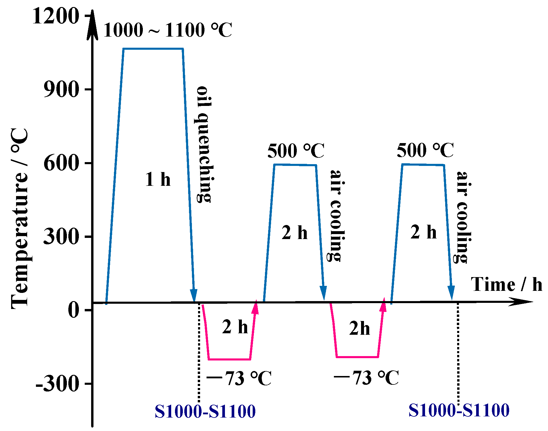
2. Materials and Methods

The nominal chemical composition (wt.%) of the experimental bearing steel is as follows: C 0.17, Co 13.0, Cr 14.0, Mo 5.0, Ni 2.0, W 0.1, V 0.1, Nb 0.1, Si 0.1, and Mn 0.03 (Fe balance). The steel was produced via vacuum induction melting and vacuum arc remelting, followed by forging into 90 mm diameter rod bars and air cooling down to room temperature. The microstructure of the experimental bearing steel in this condition (Figure 1) consists of a ferrite matrix and small amount of block austenite (0.78% in volume).
Figure 2 shows the heat treatment scheme, which includes solid solution treatment, cryogenic treatment, and tempering. Experimental samples were cut from the forged bar and then austenitized at different temperatures (1000, 1030, 1050, 1080, and 1100 °C) for 1 h followed by quenching into oil. Samples were also additionally held at −73 °C for 2 h, heated in air to room temperature, and tempered at 500 °C for 2 h with this process being repeated twice in total. In the following, the fully heat-treated samples are named T1000–T1100, with the number again representing the initial solid solution treatment temperature.
Specimens were all prepared via wire cutting along the longitudinal (rod bar axis) direction. For microstructure characterization, a solution of 1 g of CuCl2, 3.5 g of FeCl3, 2.5 mL of HNO3, 50 mL of C2H5OH, 50 mL of HCl, and 50 mL of H2O was used for metallographic etching. The samples were soaked for 30–90 s at room temperature. The microstructure and secondary phases were observed using a JSM-IT300 and JSM-IT800 (JEOL, Tokyo, Japan) scanning electron microscope (SEM). Samples for transmission electron microscope (TEM) analysis were prepared by grinding the samples to 50 μm in thickness and then thinning them using a twin-jet electropolisher in an electrolyte consisting of 6% HClO4 in ethanol at −25 °C to −30 °C. The microstructure and precipitates were observed and analyzed in a TEM of Tecnai G2 F20 (Frequency Electronics, Inc., New York, NY, USA) operated at 200 kV and equipped with an Oxford Instruments energy dispersive spectrum (EDS) detector. The Digital-Micrograph (DM) software (Version 3.7.4) was used to measure the average width of the martensite lamellae and the thickness of austenite film and index the secondary phases and nanoprecipitates.
An X-ray diffractometer XRD, BRUKER D8 ADVANCE X (Bruker Corporation, Billerica, MA, USA) with a Co target was used for the measurement of the phase volume fraction and dislocation density in the samples. A scanning angle range from 45° to 115° was used, at a tube current of 40 mA, a tube voltage of 35 kV, and a scan speed of 2°/minute. A direct comparison method was used to determine the austenite volume fraction as follows:
1/fγ = 1 + Iα Cγ/Iγ Cα
where fr is the volume fraction of austenite, and Iγ and Iα are the integrated intensities of the austenite and martensite peaks, respectively. Cγ and Cα depend on HKL, θ, and the type of substance, and Cγ/Cα is generally a coefficient for a certain lattice plane in steel.
The (200)α, (211)α, (200)γ, (220)γ, and (311)γ diffraction peaks were used to measure the integrated intensities.
The average values of crystallite size D and microstrain <ε2>1/2 were estimated according to the Williamson–Hall equation [17,18] by using the profiles of the (110)α, (220)α, and (211)α diffraction peaks after Gaussian curve fitting. The dislocation densities, ρ, could be determined via the following equation [17]:
ρ = 3 2 π < ε 2 > 1 / 2 D b
where b is the Burgers vector.
Dog-bone-shaped samples with gauge dimensions of Ø 5 mm × 30 mm were machined for tensile testing. Tensile tests were conducted according to the Chinese national standard GB/T 228 using a Zwick Z250rTL testing machine (ZwickRoell Group, Ulm, Bavaria, Germany) to measure the strength and ductility of the samples. Impact tests were performed on a Wance PIT752H machine (Shenzhen Wance Testing Equipment Co., Ltd, Shenzhen, China) using U-notch Charpy specimens with dimensions of 10 mm × 10 mm × 55 mm and a notch depth of 2 mm. The Vickers hardness of the T1100 sample was tested on a fully automatic Vickers hardness tester Wilson Tukon 2500 (Wilson, Norwood, MA, USA) with a load of 9.8 N and a dwell time of 10 s. Rockwell hardness was measured on all heat-treated samples using a Wilson RB2000-T (Wilson, Norwood, MA, USA) testing machine. The average hardness of each sample was calculated using at least three effective hardness values.

3. Results

3.1. Retained Austenite Content and Dislocation Density

Figure 3a shows the XRD patterns of samples T1000–T1100. With increasing solid-solution temperature, the intensities of the retained austenite (RA) diffraction peaks, (111)γ, (200)γ, and (220)γ, all gradually increase, indicating an increase in retained austenite content with increasing solid solution temperature. On the contrary, the intensities of the three martensite diffraction peaks, (110)α, (200)α, and (211)α, all gradually decrease. A plot of RA content as a function of solid solution temperature, Figure 3b, also demonstrates a continuous increase in RA content with that in solid solution temperature. The RA content of the T1000 sample is as low as 5.5%, while the RA content of the T1100 sample is as high as 39.7%.
Figure 3b also shows of a plot of dislocation density versus solid solution temperature. It is seen that the dislocation density decreases from 6.2 × 1011 cm−2 in T1000 to 5.1 × 1011 cm−2 in T1030, changes slightly in T1050, increases rapidly to 8.2 × 1011 cm−2 in T1080, and finally decreases slightly to 7.8 × 1011 cm−2 in T1100. The results are consistent with those for Cr–Co–Mo–Ni–C stainless steels studied by Liu [19], where values in the range of 6~7 × 1011 cm−2 were reported.

3.2. SEM Microstructure

Figure 4a–c shows SEM backscatter electron (BSE) images of secondary-phase particles undissolved into the matrix during the solution treatment of samples T1000, T1050, and T1100. Secondary-phase particles are distributed almost evenly in the matrix, albeit with some distributed in chains. Compared with T1000, there are fewer secondary-phase particles in sample T1050, and the particle size is smaller, as shown in Figure 4b. As the austenitization temperature is increased to 1100 °C, most of the secondary-phase particles are dissolved into the matrix, with only a few particles remaining. High-resolution SEM images of the samples are shown in Figure 4d–i. They reveal that the length of martensite lamellae increases with the increase in the solid solution temperature, and the secondary-phase particles and nanoprecipitates are distributed either at grain boundaries or in the grain interiors.

3.3. Precipitation and Retained Austenite

Figure 5 shows TEM images of the T1050 sample. A considerable amount of twinning in the martensitic matrix is found, as shown in Figure 5a,b. The average width of the martensite lamellae was measured to be about 0.1~0.2 μm. A twinned structure is a common feature in secondary hardening steels with a low martensite start temperature [20,21]. Lü et al. [22] reported similar findings in a low-carbon bearing steel, and demonstrated that these twins were formed during quenching and tempering. Zhang [23] also found twins in a S53 steel that were produced during a quenching and deep cooling treatment.
Within the microstructure, two kinds of austenite with different morphologies were also detected, namely block austenite and film austenite, as shown Figure 5a. Corresponding dark-field images and selected-area electron diffraction (SAED) patterns of the two kinds of austenitic phases are shown in Figure 5b,c. The thickness of film austenite was measured to be about 0.2–0.3 μm. The block austenite exhibits a Kurdjumov–Sachs (K–S) orientation relationship with the martensite, i.e., (−1 −11)γ∥(−10 −1)α and [011]γ∥[111]α. The lattice constants of martensite and austenite were measured to be 0.293 nm and 0.358 nm, respectively. In addition, a high dislocation density was found in the martensitic matrix, as shown in Figure 5d.
Figure 6 shows TEM observations of the secondary phase and precipitates in sample T1050. One of the large granular carbides (Figure 6a), the undissolved secondary phase, is nearly elliptical, with a long axis measuring about 500 nm and a short axis measuring 400 nm. Selected-area electron diffraction (SAED) patterns (Figure 6c) indicate that the diffraction spots are from M6C carbides, which EDS measurements show to mainly contain Mo, Fe, W, Cr, Co, Nb, and V, as shown in Figure 6b. A number of nano-sized precipitates with either a granular or needle shape are also observed in the matrix, as shown in Figure 6d–f. Due to the fine scale of these precipitates, HRTEM (high-resolution TEM) characterization was additionally carried out for further analysis.
Figure 7 shows HRTEM images of nano-scale precipitates. Diffraction spots from the precipitates, obtained via fast Fourier transform (FFT) in the red areas in Figure 7a and Figure 7b, are shown in Figure 7c and Figure 7d, respectively. It is seen that the precipitates in Figure 7a,c are M2C carbides with a hexagonal structure (hcp), which is consistent with the results in Refs. [20,24,25]. The M2C carbides are present with a needle shape of a width of about 2~3 nm, and obey an orientation relationship with the martensitic matrix given by [01 - 11]M2C∥[001]α and (0 - 112)M2C∥(−110)α. The precipitates in Figure 7b,d are identified as M6C carbides, with a face-centered cubic structure (fcc), and a lattice constant equal to 1.127 nm. These M6C carbides are present as spheroidal particles with a diameter of 2~3 nm and an orientation relationship with the martensitic matrix given by [114]M6C∥[001]α and (−31 - 1)M6C∥(−110)α. M6C carbides were also reported in a S53 steel variant and a Cr–Co–Mo–Ni bearing steel [26] as primary carbides albeit with a much larger size of hundreds of nanometers. In addition, Dyson [27] reported the precipitation of M2X and M6C carbides in a 12%Cr–6%Mo–10%Co stainless maraging steel, and confirmed a carbide reaction of M2X→M6C, as was found previously in high-speed steels [28].

3.4. Mechanical Properties

Figure 8 shows the engineering stress–strain curves and corresponding true stress–strain curves for the experimental steels. As shown in Figure 8a, the ultimate tensile stresses are almost independent of solid solution temperature. In contrast, yield strength decreases, and uniform elongation increases with increasing solution temperature. Figure 8b shows the true stress–strain curves where it is seen that the true ultimate tensile strengths for the T1000–T1100 samples are 2146 MPa, 2183 MPa, 2216 MPa, 2317 MPa, and 2411 MPa. The maximum tensile true stresses and the total tensile true strains both increase with increasing solution temperature, which indicates that toughness also increases with solution temperature.
Table 1 summarizes the mechanical properties of the T1000–T1100 samples. For solution temperatures lower than 1080 °C, tensile strength (TS, Rm) increases continuously from 1779 MPa to 1830 MPa while yield strength (YS, Rp0.2) decreases gradually from 1530 MPa to 1372 MPa with solution temperature. As the solution temperature is raised above 1080 °C, the TS decreases slightly to 1802 MPa and the YS decreases greatly to 1016 MPa. The Rockwell hardness (HRC) measurements follow a similar trend to those of YS with solution temperature. Over the whole investigated solution temperature range, section shrinkage (Z) increases almost linearly with solution temperature, from 48% to 59.5%. Elongation (A) follows a similar trend to that of section shrinkage, increasing from 15% to 20.5%, with the exception of the sample treated at 1050 °C, which has an elongation that is slightly lower than that of the sample treated at 1030 °C. The increase in A and Z also suggests that toughness increases with increasing solid-solution temperature. This is confirmed directly by the data in Figure 8d, showing that impact toughness increases with solid solution temperature, over the temperature range of 1000 °C to 1080 °C, and impact toughness increases nearly linearly with solution temperature, increasing from 37.0 J to 52.3 J. As the solution temperature is raised to 1100 °C, the impact toughness increases significantly to 86.2 J.

4. Discussion

4.1. Mechanical Properties of the Developed Ultrahigh-Strength Steels and Bearing Steels

The strength and toughness values of the new steel are compared to values for other ultrahigh-strength steels and bearing steels, based on data collected from the open literature [14,15,29,30,31,32,33]. Figure 9a shows a scatter plot of elongation versus tensile strength. For an easy guide to the eye, the upper limit of elongation versus tensile strength previously studied steels is also plotted in (a), as shown by the red dashed line. The upper limit of elongation decreases with increasing tensile strength, which obeys a combined inverse strength–ductility relationship and an inverse strength–toughness relationship [18]. At the 1800 MPa strength grade, indicated by the purple vertical dashed line, the elongation upper limit is 16%, corresponding to that of CSS-42L steel. In contrast, samples T1080 and T1100 of the new test steel have elongations as high as 18.5% and 20.5%, respectively. A scatter plot of strong plastic product versus tensile strength is shown Figure 9b. The upper limit for previously reported steels is also shown by a red dashed line, which shows a trend of increase first and then of decrease, with peak values of 30.3 GPa·% and 30.4 GPa·% corresponding to FerriumM54 and AerMet310, respectively. At the 1800 MPa strength grade, as shown by the purple dashed line, samples T1080 and T1100 in the present study have higher strong plastic products, with values of 33.9 GPa·% and 37.0 GPa·%, respectively. Therefore, the newly developed test steel can achieve superior strength and toughness compared to those of previously reported ultrahigh-strength steels and bearing steels.

4.2. Strengthening and Toughening Mechanism

Compared with other stainless bearing steels with similar alloy compositions, the RA content of the test steel is relatively high. For example, the RA content of Ferrium S53 steel is 35.5% after solid solution treatment at 1080 °C for 1 h, decreasing to 3.2% after a 500–550 °C tempering treatment [34], and that of a Fe–Cr–Co–Mo–Ni–C stainless steel [19] is only 16.4% after solid solution treatment at 1100 °C and tempering at 540°C. Shi [35] found that the stress–strain curves of an ultrafine duplex Mn–TRIP steel exhibited an “S” shape, and attributed this to the transformation-induced plasticity (TRIP) effect of retained austenite. The present experimental steel also exhibits “S”-shaped engineering stress–strain curves (Figure 8), similar to those reported in Ref. [35], and high RA contents are also found in these steel samples (Figure 3). It is thus speculated that the excellent strength and toughness of the steel in the T1080 and T1100 condition results from the TRIP effect during tensile testing, promoted by the high RA content. Another characteristic feature of the TRIP effect is a relatively low yield ratio [36]. This is also confirmed to be the case in the newly developed steel, as the yield ratio gradually decreases from 0.86 to 0.57 as the RA content increases from 5.5% to 39.7%. The Vickers hardness of austenite HV(RA) and martensite (HV(M)) in the T1100 sample were measured, indicating average values of 306 HV1 and 495 HV1, respectively. The yield strength is normally determined by the retained austenite and the tensile strength is controlled by martensite. The yield ratio can therefore be roughly estimated via the ratio of HV(RA)/HV(M), which is calculated to be 0.62, this being close to the measured yield ratio of 0.57.
The strength of martensitic ultrahigh-strength steel can be approximately rationalized via the additive consideration of the strength increments due to solid solute elements, grain boundaries, dislocations, and precipitation [18,37], as expressed via the following equation:
σ = σ0 + σss + σd + σp + σg
where σ is the total strength, σ0 is the internal fictional stress of body-centered cubic (BCC) iron (about 50 MPa [18]), σd is the strengthening from a high dislocation density (dislocation strengthening), σg is from grain boundaries (fine grain strengthening), σss is the strength caused by solid solutes (solid solution strengthening), and σp is from precipitates (precipitation strengthening).
With increasing solid solution temperature, granular M6C carbides are dissolved into high-temperature austenite, which increases the alloy content of the heat-treated martensite, resulting in an increased solid solution strength increment (σss). However, solid solution strengthening (σss) is relatively low, at only 92 MPa, as reported in Ref. [18]. Nano-sized precipitates and dislocation strengthening seem therefore to play the most important role in determining overall strength [18,34].
The dislocation contribution (σd) can be estimated using the Taylor hardening law [18,37]:
σd = MαGb√ρ
where M is the Taylor factor (taken as 2.8 for BCC metals), α equals 0.20 for a high dislocation density, G is the shear modulus (80.7 GPa), b is the Burgers vector (0.248 nm), and ρ is the measured dislocation density. σd is calculated to be 882.5 MPa, 800.3 MPa, 800.3 MPa, 1014.9 MPa, and 989.8 MPa for T1000, T1030, T1050, T1080, and T1100, respectively. The dislocation strengthening contribution therefore nearly exceeds (or for some samples exceeds) 50% of the total strength.
The strength increment due to the precipitation (σp) can in theory be calculated according to a particle shearing mechanism. However, the volume fraction of nanoprecipitates of M2C and M6C cannot be precisely determined due to their very fine size. As shown in Refs. [23,27,34,38], the precipitation behavior of such steels is more closely related to the temperature and time of tempering, rather than to the solid solution temperature. In the present study, at a lower solid solution temperature, there are more undissolved secondary phases, which may have a greater effect on the number and size of nanoprecipitates during tempering. It is suggested that this is one of the reasons for the small strength increment with solid solution temperature, as shown in Table 1. In addition, large undissolved M6C secondary phases, which are incoherent with the matrix, can act as stress concentration areas during tensile deformation, and are deleterious for both strength and toughness. In contrast, smaller undissolved M6C secondary phases may provide an advantage in this regard, as they can pin austenite grain boundaries, thereby retarding grain boundary migration before they are dissolved into the austenite matrix [39].
Regarding fine grain strengthening, the strength increment, σg, is assumed to follow a Hall–Petch law, i.e., σg = kHP·d−1/2, where kHP is the Hall–Petch slope (120 MPa·μm1/2), and d is the width of the martensite lamellae, 0.1~0.2 μm (Figure 5). Accordingly, σg is calculated to be 268.3~379.5 MPa. From this analysis, it can be concluded that dislocation strengthening plays the most important role in determining overall strength.
The variation in dislocation density may be closely related to the microstructure, main alloying elements, nanoprecipitation, and RA content [40]. The high dislocation density of the present test steel is mainly attributed to a synergistic effect of Co additions and the nanoprecipitation of M2C and M6C carbides. Banerjee and Hauser studied the effect of Co in maraging steels and suggested that the addition of Co lowered the stacking fault energy of the BCC lattice, which resulted in a higher dislocation density in the as-quenched or cryogenic condition [41]. In addition, Speich [41] reported that Co is effective in retarding the rate of recovery of the martensite dislocation substructure. Alloy carbides preferentially nucleate at dislocations because they provide energetically more favorable sites than matrix nucleation sites. As the secondary hardening precipitate M2C is dislocation-nucleated, a higher dislocation density also provides more sites for nucleation and thus results in a finer dispersion of precipitates at the tempering stage. Under the expansion stress of the γ → α phase transformation, dislocations pinned by precipitates in the martensite can migrate, resulting in dislocation multiplication during the second cryogenic treatment, which in turn can further promote the precipitation of M2C during the second tempering treatment. The reason for the increasing dislocation density with the increasing solution temperature in the temperature range of 1030~1080 °C is probably due to the increase in the density of nanoprecipitates formed as undissolved secondary phases of M6C increasingly dissolve back into the matrix with higher solution temperature. Investigations on Ferrium S53 steel also found that dislocation density increased with increasing solid solution temperature [39]. The higher dislocation density of T1000 compared to that of T1030 is attributed to the higher martensite content, and the lower dislocation density of T1100 compared to that of T1080 is attributed to the higher retained austenite content.

5. Conclusions

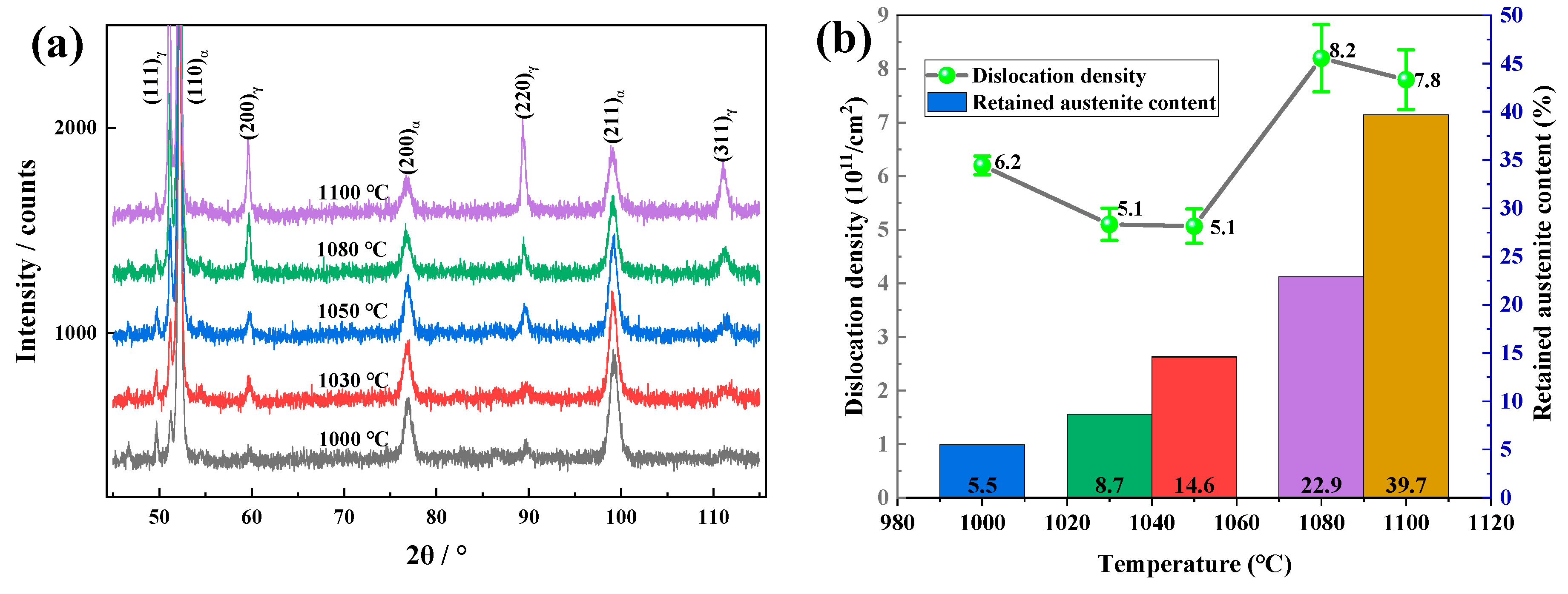
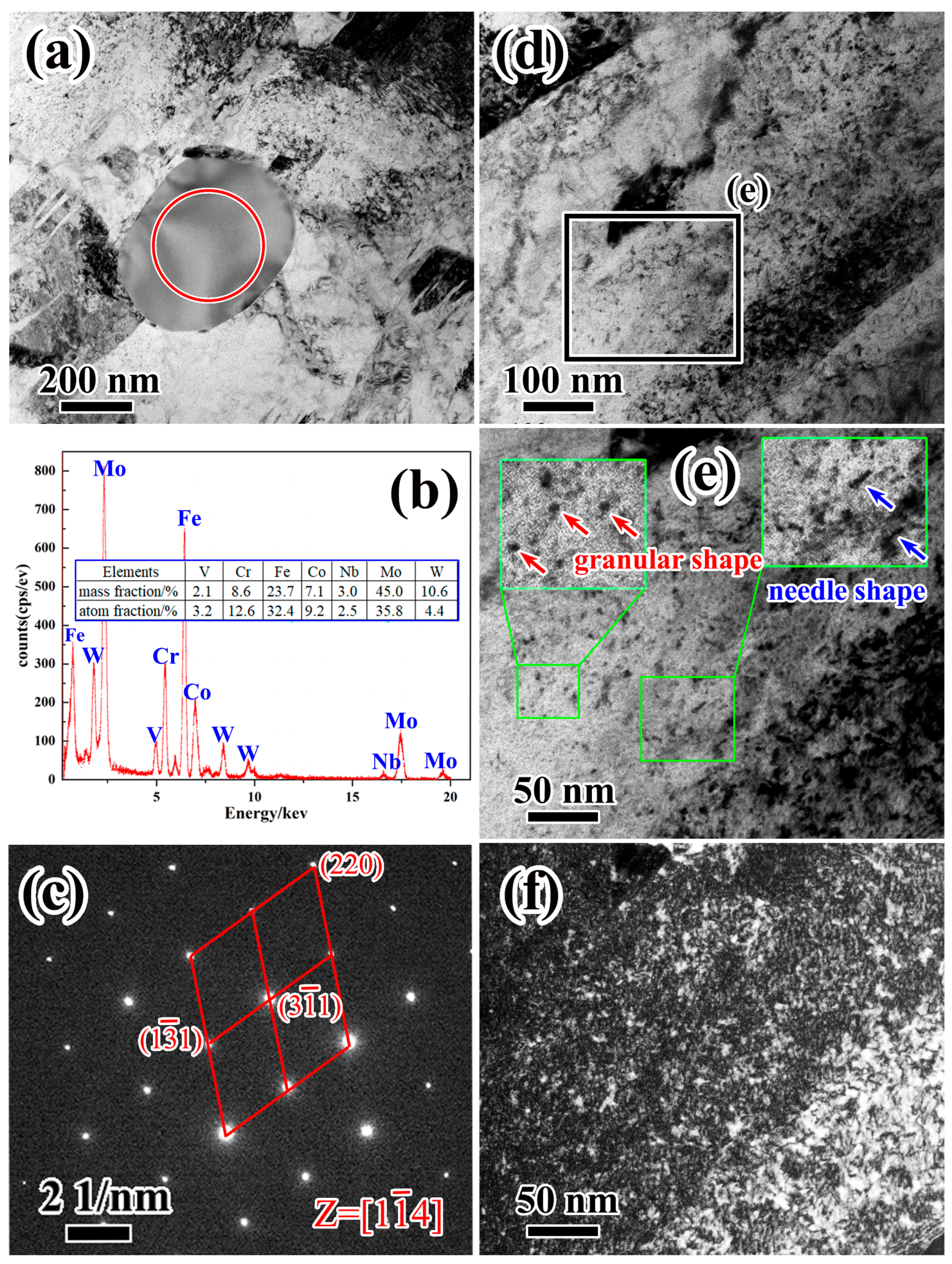
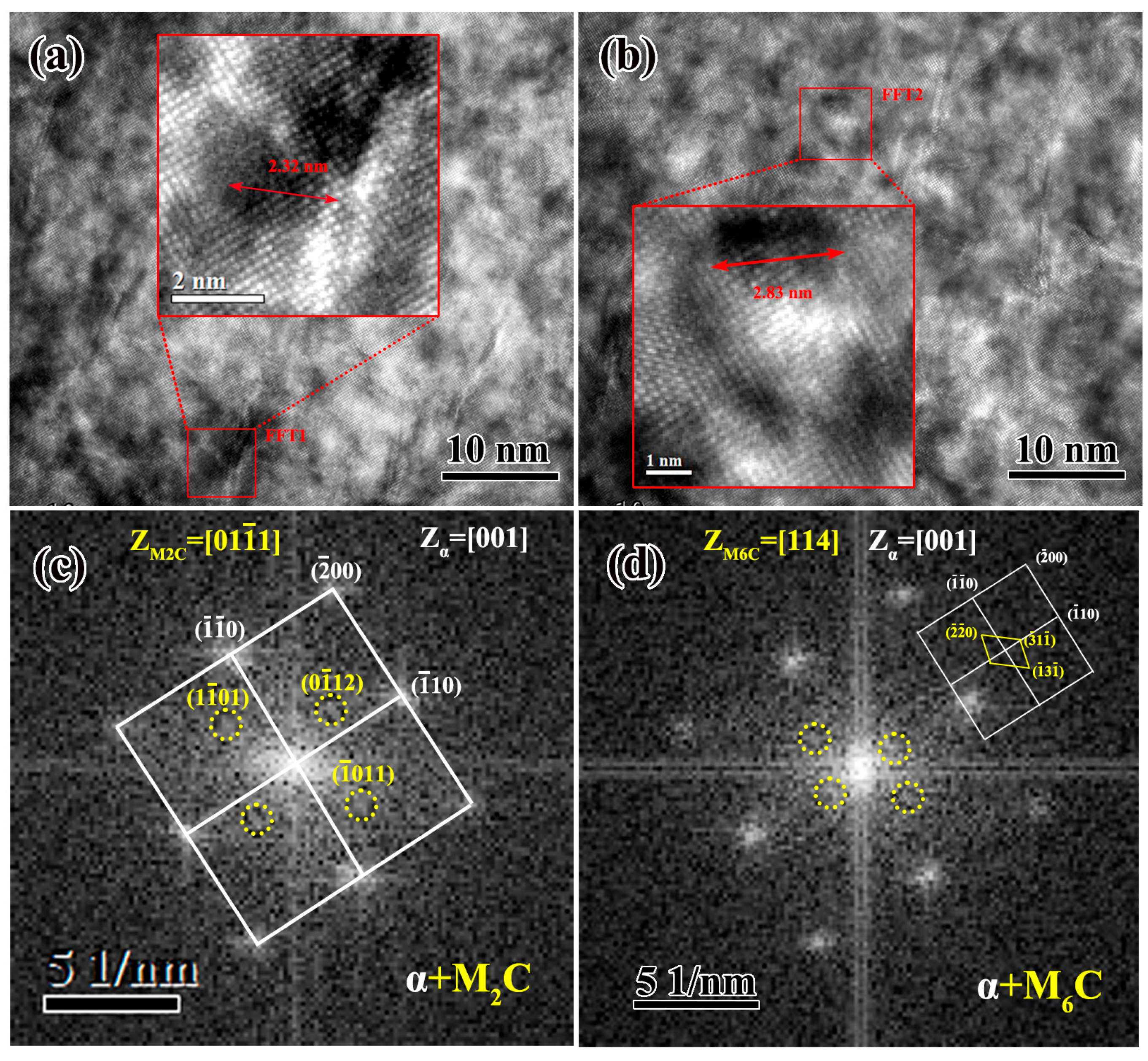
  • With an increasing solid solution temperature, the retained austenite content increases to as high as 39.7% at a solution temperature of 1100 °C and the dislocation density reaches a peak value of 8.2 × 1011 cm−2 at a solution temperature of 1080 °C. TEM and HRTEM analyses reveal that the microstructure of samples tempered at 500 °C have a high density of tangled dislocations, together with film austenite with a thickness of 0.2~0.3 nm, and nanoprecipitates of M2C and M6C carbides, where both types of precipitate retain coherence with the martensite matrix. M2C carbides are present in a needle shape, with a width of 2~3 nm, and follow a [01 - 11]M2C∥[001]α-and (0 - 112)M2C∥(−110)α-orientation relationship with the martensitic matrix. M6C carbides are present with a spheroidal shape with a diameter of 2~3 nm, and follow a [114]M6C∥[001]α- and (−31 - 1)M6C∥(−110)α-orientation relationship with the martensitic matrix.
  • Tensile strength and Rockwell hardness both increase gradually with increasing solid solution temperature up to 1080 °C, reaching peak values of 1830 MPa and 51.4 HRC, respectively, and then decrease rapidly with a further increase in solution temperature. Yield strength decreases linearly (to 1372 MPa) with increasing solution temperatures to up to 1080 °C, and then descends rapidly to 1033 MPa at higher solution temperatures. The representative toughness indexes of elongation, section shrinkage, and impact absorbed energy all increase with increasing solution temperature to reach maximum values. Excellent values of the strong plastic product, representing a combination of strength and toughness, are achieved after tempering at 1080 °C (33.9 GPa·%) and 1100 °C (37.0 GPa·%), both of which are far higher than the temperatures for any other ultrahigh-strength steel or bearing steel ever reported.
  • The super-high strength and toughness of the newly developed steel is mainly attributed to the TRIP effect, promoted by a high retained austenite content, and to strong dislocation strengthening caused by a high dislocation density. The dislocation strengthening contribution is estimated as 1014.9 MPa in the sample tempered at 1080 °C, exceeding 50% of the total strength. The high dislocation density in the heat-treated samples is mainly attributed to the synergistic effect of cobalt addition and to the nanoprecipitation of M2C and M6C carbides.
As a case-hardenable stainless bearing steel, obtaining excellent mechanical properties only in the core is not enough. We have attempted to implement surface carburization and achieve a high surface hardness that is above 800 HV with a hardened layer measuring about 1 mm, showing broad prospects in the use of this steel in stainless bearings. Next, it is urgent to explore and optimize the carburization process to achieve excellent rolling contact fatigue performance and corrosion resistance. Furthermore, this novel steel is also promising in terms of its use as an ultrahigh-strength stainless steel in cams, shafts, bolts, gears, and other parts involved in working at high temperatures and/or corrosive atmospheres.

Author Contributions

Conceptualization, W.C.; data curation, K.Z.; formal analysis, Z.Z., H.W., H.X., F.Y. and C.W.; funding acquisition, W.C.; investigation, K.Z., Z.Z., H.W., H.X., F.Y. and C.W.; project administration and writing—review and editing: J.L.; supervision, W.C.; writing—original draft, K.Z.; writing—review and editing, G.W., A.G. and W.C. All authors have read and agreed to the published version of the manuscript.

Funding

This research was supported by the National Natural Science Foundation of China (no. 51871062 and 52071038) and a key project of CISRI (no. shi20T61200ZD).

Data Availability Statement

The data that have been used are confidential.

Conflicts of Interest

The authors declare that they have no known competing financial interests or personal relationships that could have appeared to influence the work reported in this paper. There are no financial interests/personal relationships which may be considered potential competing interests.

References

  1. Trivedi, H.K.; Forster, N.H.; Rosado, L. Rolling contact fatigue evaluation of advanced bearing steels with and without the oil anti-wear additive tricresyl phosphate. Tribol. Lett. 2011, 41, 597–605. [Google Scholar] [CrossRef]
  2. Wang, F.F.; Li, Q.S.; Zheng, L.J.; Zhang, F.X.; Zhang, H. Microstructure and corrosion characterization of Cr film on carburized CSS-42L aerospace bearing steel by filtered cathodic vacuum arc deposition. Coatings 2018, 8, 313. [Google Scholar] [CrossRef]
  3. Yin, L.C.; Ma, X.X.; Tang, G.Z.; Fu, Z.Y.; Yang, S.X.; Wang, T.J.; Wang, L.Q.; Li, L.H. Characterization of carburized 14Cr14Co13Mo4 stainless steel by low pressure carburizing. Surf. Coat. Technol. 2019, 358, 654–660. [Google Scholar] [CrossRef]
  4. Tomasello, C.M.; Burrier, H.I.; Knepper, R.A.; Balliett, S.; Maloney, J.L. Progress in the evaluation of CSS-42L(TM): A high performance bearing alloy. In Bearing Steel Technology; Beswick, J.M., Ed.; American Society for Testing and Materials (ASTM) International: West Conshohocken, PA, USA, 2002; pp. 375–385. [Google Scholar] [CrossRef]
  5. Bhadeshia, H. Steels for bearings. Prog. Mater. Sci. 2012, 57, 268–435. [Google Scholar] [CrossRef]
  6. Guan, J.; Wang, L.; Zhang, Z.; Shi, X.; Ma, X. Fatigue crack nucleation and propagation at clustered metallic carbides in M50 bearing steel. Tribol. Int. 2018, 119, 165–174. [Google Scholar] [CrossRef]
  7. Nygaard, J.R.; Rawson, M.; Danson, P.; Bhadeshia, H. Bearing steel microstructures after aircraft gas turbine engine service. Mater. Sci. Technol. 2014, 30, 1911–1918. [Google Scholar] [CrossRef]
  8. Wang, F.F.; Zhang, F.X.; Zheng, L.J.; Zhang, H. Structure and corrosion properties of Cr coating deposited on aerospace bearing steel. Appl. Surf. Sci. 2017, 423, 695–703. [Google Scholar] [CrossRef]
  9. Forster, N.H.; Rosado, L.; Ogden, W.P.; Trivedi, H.K. Rolling Contact Fatigue Life and Spall Propagation Characteristics of AISI M50, M50NiL, and AISI 52100, Part III: Metallurgical Examination. Tribol. Trans. 2010, 53, 52–59. [Google Scholar] [CrossRef]
  10. Maloney, J.L.; Tomasello, C.M. Case Carburized Stainless Steel Alloy for High Temperature Applications. U.S. Patent 5,424,028, 13 June 1995. [Google Scholar]
  11. Burrier, H.I.; Milam, L.; Tomasello, C.M.; Balliett, S.A.; Maloney, J.L.; Ogden, W.P. Development of CSS-42LTM, a high performance carburizing stainless steel for high temperature aerospace applications. In Proceedings of the Symposium on Bearing Steels: Into the 21st Century ASTM Committee A-1 on Steel, New Orleans, LA, USA, 19–21 November 1996; ASTM: Ann Arbor, MI, USA, 1998. [Google Scholar]
  12. Yu, F.; Chen, X.P.; Xu, H.F.; Dong, H.; Weng, Y.Q.; Cao, W.Q. Current status of metallurgical quality and fatigue performance of rolling bearing steel and development direction of high-end bearing steel. Acta Metall. Sin. 2020, 56, 513–522. [Google Scholar] [CrossRef]
  13. Gobber, F.S.; Bidulská, J.; Fais, A.; Bidulský, R.; Grande, M.A. Innovative Densification Process of a Fe-Cr-C Powder Metallurgy Steel. Metals 2021, 11, 665. [Google Scholar] [CrossRef]
  14. Yang, K.; Niu, M.C.; Tian, J.L.; Wang, W. Research and development of maraging stainless steel used for new generation landing gear. Acta Metall. Sin. 2018, 54, 1567–1585. [Google Scholar] [CrossRef]
  15. Luo, H.W.; Shen, G.H. Progress and perspective of ultra-high strength steels having high toughness. Acta Metall. Sin. 2020, 56, 494–512. [Google Scholar] [CrossRef]
  16. Pioszak, G.L.; Gangloff, R.P. Hydrogen environment assisted cracking of modern ultra-high strength martensitic steels. Metall. Mater. Trans. A 2017, 48A, 4025–4045. [Google Scholar] [CrossRef]
  17. Dini, G.; Ueji, R.; Najafizadeh, A.; Monir-Vaghefi, S.M. Flow stress analysis of TWIP steel via the XRD measurement of dislocation density. Mater. Sci. Eng. A 2010, 527, 2759–2763. [Google Scholar] [CrossRef]
  18. Liu, T.; Cao, Z.; Wang, H.; Wu, G.; Jin, J.; Cao, W. A new 2.4GPa extra-high strength steel with good ductility and high toughness designed by synergistic strengthening of nano-particles and high-density dislocations. Scr. Mater. 2020, 178, 285–289. [Google Scholar] [CrossRef]
  19. Liu, Z.B.; Zhang, B.N.; Sha, G.; Jin, S.B.; Yang, Z.Y.; Liang, J.X.; Tian, Z.L. Effect of cobalt on precipitation in Fe-Cr-Co-Mo-Ni-C stainless steels. Mater. Lett. 2021, 289, 129439. [Google Scholar] [CrossRef]
  20. Zhang, Y.P.; Zhan, D.P.; Qi, X.W.; Jiang, Z.H.; Zhang, H.S. The role of twins during the aging process of secondary hardening ultrahigh-strength steel. Mater. Lett. 2019, 244, 83–87. [Google Scholar] [CrossRef]
  21. Machmeier, P.; Matuszewski, T.; Jones, R.; Ayer, R. Effect of chromium additions on the mechanical and physical properties and microstructure of Fe-Co-Ni-Cr-Mo-C ultra-high strength steel: Part I. J. Mater. Eng. Perform. 1997, 6, 279–288. [Google Scholar] [CrossRef]
  22. Lü, X.Y.; Wu, Z.W.; He, X.; Li, J.; Li, S.H.; Yang, M.S.; Zhao, K.Y. Effect of deep cryogenic treatment on martensitic lath refinement and nano-twins formation of low carbon bearing steel. J. Iron Steel Res. Int. 2020, 27, 105–113. [Google Scholar] [CrossRef]
  23. Zhang, Y.P.; Zhan, D.P.; Qi, X.W.; Jiang, Z.H. Austenite and precipitation in secondary-hardening ultra-high-strength stainless steel. Mater. Charact. 2018, 144, 393–399. [Google Scholar] [CrossRef]
  24. Yang, Z.; Liu, Z.B.; Liang, J.X.; Yang, Z.Y.; Sheng, G.M. Elucidating the role of secondary cryogenic treatment on mechanical properties of a martensitic ultra-high strength stainless steel. Mater. Charact. 2021, 178, 111277. [Google Scholar] [CrossRef]
  25. Seo, J.Y.; Park, S.K.; Kwon, H.; Cho, K.S. Influence of Carbide Modifications on the Mechanical Properties of Ultra-High-Strength Stainless Steels. Metall. Mater. Trans. A 2017, 48A, 4477–4485. [Google Scholar] [CrossRef]
  26. Yuan, X.H.; Zheng, S.J.; Yang, M.S.; Zhao, K.Y. Carbide precipitation and microstructure refinement of Cr-Co-Mo-Ni bearing steel during hot deformation. J. Cent. South. Univ. 2015, 22, 3265–3274. [Google Scholar] [CrossRef]
  27. Dyson, D.J.; Keown, S.R. A study of precipitation in a 12 percent Cr-Co-Mo steel. Acta Metall. 1969, 17, 1095–1107. [Google Scholar] [CrossRef]
  28. Lu, L.; Hou, L.G.; Zhang, J.X.; Wang, H.B.; Cui, H.; Huang, J.F.; Zhang, Y.A.; Zhang, J.S. Improved the microstructures and properties of M3:2 high-speed steel by spray forming and niobium alloying. Mater. Charact. 2016, 117, 1–8. [Google Scholar] [CrossRef]
  29. Zhang, C.; Su, J.; Liang, J.X.; Liu, Z.B.; Ge, Q.L. Research development of precipitation behavior of ultra high strength stainless steels. Iron Steel 2018, 53, 48–61. [Google Scholar] [CrossRef]
  30. Li, X.; Lin, F.J.; Du, S.M.; Wu, C.C. Comparative analysis of high performance bearing steels. Heat Treat. Met. 2021, 46, 14–20. [Google Scholar] [CrossRef]
  31. Liu, Z.B.; Liang, J.X.; Su, J.; Wang, X.H.; Sun, Y.Q.; Wng, C.J.; Yang, Z.Y. Research and application progress in ultra-high strength stainless steel. Acta Metall. Sin. 2020, 56, 549–557. [Google Scholar] [CrossRef]
  32. Zheng, K.; Cao, W.Q.; Yu, F.; Wang, C.Y.; Zhong, Z.Q.; Xu, H.F. The research status and progress of high temperature stainless carburized bearing steel. Iron Steel 2022, 57, 125–136. [Google Scholar] [CrossRef]
  33. Yu, X.; Shen, X.; Wang, S.; Su, Y.; Zhao, W.; Wei, Y. Effect of quenching and tempering treatment on microstructure and mechanical properties of CSS-42L bearing steel. J. Mater. Eng. Perform. 2022, 31, 5458–5466. [Google Scholar] [CrossRef]
  34. Zhang, Y.P.; Zhan, D.P.; Qi, X.W.; Jiang, Z.H. Effect of tempering temperature on the microstructure and properties of ultrahigh-strength stainless steel. J. Mater. Sci. Technol. 2019, 35, 1240–1249. [Google Scholar] [CrossRef]
  35. Shi, J.; Sun, X.; Wang, M.; Hui, W.; Dong, H.; Cao, W. Enhanced work-hardening behavior and mechanical properties in ultrafine-grained steels with large-fractioned metastable austenite. Scr. Mater. 2010, 63, 815–818. [Google Scholar] [CrossRef]
  36. Bordone, M.; Monsalve, A.; Ipiña, J.P. Fracture toughness of High-Manganese steels with TWIP/TRIP effects. Eng. Fract. Mech. 2022, 275, 108837. [Google Scholar] [CrossRef]
  37. Niu, G.; Tang, Q.; Zurob, H.S.; Wu, H.; Xu, L.; Gong, N. Strong and ductile steel via high dislocation density and heterogeneous nano/ultrafine grains. Mater. Sci. Eng. A 2019, 759, 1–10. [Google Scholar] [CrossRef]
  38. Xiao, M.G.; Lü, X.Y.; Li, D.H.; Li, S.H.; Zhao, K.Y.; Yang, M.S. Carbides precipitation and their evolution of Cr15Co10Mo5-alloyed heat-resistant bearing steel after tempering at different temperatures. J. Iron Steel Res. Int. 2019, 26, 1096–1105. [Google Scholar] [CrossRef]
  39. Zhang, Y.P.; Zhan, D.P.; Qi, X.W.; Jiang, Z.H. Effect of solid-solution temperature on the microstructure and properties of ultra-high-strength ferrium S53 steel. Mater. Sci. Eng. A 2018, 730, 41–49. [Google Scholar] [CrossRef]
  40. Yasnikov, I.S.; Kaneko, Y.; Uchida, M.; Vinogradov, A. The grain size effect on strain hardening and necking instability revisited from the dislocation density evolution approach. Mater. Sci. Eng. A 2022, 831, 142330. [Google Scholar] [CrossRef]
  41. Speich, G.R.; Dabkowski, D.S.; Porter, L.F. Strength and toughness of Fe-10Ni alloys containing C, Cr, Mo, and Co. Metall. Trans. 1973, 4, 303–315. [Google Scholar] [CrossRef]
Figure 1. Microstructure of the as-forged bearing steel: (a) metallographic image, with the ferrite matrix (light grey) and small amount of block austenite (dark grey) located at the boundaries; (b) phase distribution map of electron backscatter diffraction (EBSD), with the ferrite matrix marked with blue and small amount of block austenite marked with red.
Metals 13 01824 g001
Figure 2. Illustration of the heat treatment scheme including the solution treatment for 1 h in the temperature range from 1000 to 1100 °C followed by quenching into oil, and then two cycles of cryogenic treatment at −73 °C for 2 h and tempering at 500 °C for 2 h, with final air cooling to room temperature.
Metals 13 01824 g002
Figure 3. (a) XRD patterns, and (b) austenite content and dislocation density of samples T1000–T1100.
Metals 13 01824 g003
Figure 4. BSE images of secondary phases (ac), and high-resolution SEM images of the martensitic matrix (di) in T1000 (a,d,g), T1050 (b,e,h), and T1100 (c,f,i): martensite lamellae, secondary phase particles and nano precipitates are marked by dotted line ellipticals and blue arrows respectively.
Metals 13 01824 g004
Figure 5. TEM images of sample T1050: (a) bright-field image; (b) corresponding dark-field image of (a); (c) SAED pattern of austenite of the area indicated by red circle in (a); (d) a high density of dislocations.
Metals 13 01824 g005
Figure 6. TEM observation of secondary phase and precipitates in sample T1050: (a) bright-field image of secondary phase; (b) energy-dispersive spectrum; and (c) SAED pattern from the red circle area of a large granular secondary phase in (a); (d) low magnification and (e) high magnification bright-field images showing nano-scale precipitates; (f) corresponding dark-field image of (e).
Metals 13 01824 g006
Figure 7. FFT and diffraction calibration (c) of the needle-like M2C in the red box in (a); FFT and diffraction calibration (d) of the granular-like M6C in the red box in (b).
Metals 13 01824 g007
Figure 8. Mechanical properties as a function of solid solution temperature: (a) engineering stress–strain curves, (b) true stress–strain curves, (c,d) plots of hardness, tensile strength, yield strength, elongation, reduction area, and impact absorbed energy versus solid solution temperature.
Metals 13 01824 g008
Figure 9. Plots of elongation (a) and strong plastic product (b) versus tensile strength for different steels: the mechanical of ultrahigh strength steels, stainless bearing steel and this novel steel plotted by black, red and purple scatter points, respectively.
Metals 13 01824 g009
Table 1. Mechanical properties of samples T1000–T1100.
SampleYield Strength (Rp0.2)/MPaUltimate Tensile Strength (Rm)/MPaElongation (A)/%Section Shrinkage (Z)/%Impact Absorbed Energy (Aku)/J
T10001530 ± 11778 ± 215.3 ± 0.248.5 ± 0.537.0
T10301493 ± 81803 ± 716.0 ± 0.551.0 ± 0.041.7
T10501444 ± 11822 ± 015.5 ± 0.552.5 ± 0.544.6
T10801372 ± 11830 ± 118.5 ± 0.056.0 ± 1.052.3
T11001033 ± 171806 ± 420.5 ± 0.559.5 ± 0.586.2
Disclaimer/Publisher’s Note: The statements, opinions and data contained in all publications are solely those of the individual author(s) and contributor(s) and not of MDPI and/or the editor(s). MDPI and/or the editor(s) disclaim responsibility for any injury to people or property resulting from any ideas, methods, instructions or products referred to in the content.

