Article

Holistic Investigation of the Inert Thermal Treatment of Industrially Shredded NMC 622 Lithium-Ion Batteries and Its Influence on Selective Lithium Recovery by Water Leaching

by
Christin Stallmeister
* and
Bernd Friedrich
IME, Institute for Process Metallurgy and Metal Recycling, RWTH Aachen University, 52056 Aachen, Germany
*
Author to whom correspondence should be addressed.
Metals 2023, 13(12), 2000; https://doi.org/10.3390/met13122000
Submission received: 13 November 2023 / Revised: 8 December 2023 / Accepted: 10 December 2023 / Published: 12 December 2023

Abstract

:
The thermal treatment of lithium-ion batteries is an already industrially implemented process step in some recycling chains. It provides the advantages of controlled organic removal and conditioning of the black mass for further process steps, such as water-based early-stage lithium recovery. Therefore, a deep understanding of ongoing reactions and the influence of the process parameters on the reaction products is crucial. This study investigates the inert thermal treatment of an industrial end-of-life NMC 622 battery shredder in a 200 g scale regarding the influence of process parameters on the reaction products, separation of black mass, and its water leaching. Therefore, the off-gas produced during the thermal treatment was analyzed by FTIR, and afterwards, a sieve classification of the shredder was carried out. The separated black mass was further analyzed for residual organics by pyrolysis GC-MS and for its phase composition by XRD. A water leaching of the different thermally treated black masses was carried out for Li recovery. Occurring reactions during the thermal treatment process, such as the different stages of organic removal and reduction reactions in the active material, were derived based on the collected data. These reactions mainly affect the water-based Li recovery, which is related to Li2CO3 generation. The maximum pyrolysis temperature has the greatest effect on the Li recovery. After a treatment at 642 °C, 62.4% of Li was leached. Reactions of the co-elements F, P and Al with Li during the thermal treatment were identified as the limiting factors regarding Li recovery.

1. Introduction

Thermal treatment is a promising and already industrially implemented [1] process step in recycling chains. It offers the opportunity for the conditioning of organic-containing material before entering metallurgical recovery steps [1,2]. In the frame of battery recycling, it is recommended for whole batteries or modules, as well as shredded battery material or production scrap [1]. Typically, the process is carried out in advance of mechanical separation steps [1,2,3,4]. The resulting black mass enters the hydro- or pyrometallurgical process steps [1,2,4].
The thermal treatment provides different advantages for the recycling of lithium-ion batteries (LIBs). In the case of whole cells or modules, the thermal treatment includes a controlled deactivation [3,4]. This allows simplified shredder processes with conventional methods [1]. Alternatively, inert gas, cryogenic or water shredding can be carried out first [1,2,5,6]. The thermal treatment removes organics originating from electrolytes, separators and binders. Binder removal improves the separation of the valuable active mass from the collector foils during mechanical separation. Yang et al. [7] observed complete separation of active mass from out-of-spec NMC collector foils in the case of PVDF as binder material for treatment temperatures above 550 °C. Similar results were achieved by Lombardo et al. [8]; the mechanical separation of NMC from aluminum foils was improved by raising the temperature and time in thermal treatment. A limitation is the melting point of aluminum (660.3 °C [9]), which results in decreasing recovery rates from 650 °C onwards [8]. Zhang et al. [10] defined the optimum temperature for binder removal and delamination for a mix of cathode and anode foils from LCO mobile phone batteries to be 500 °C.
In addition to the binder, the electrolyte can be removed during the thermal treatment. Especially in the case of hydrometallurgical treatment, the removal of both, binder and electrolyte, is advantageous due to enhanced leaching efficiencies (LE), as described by Petranikova et al. [11] and Vieceli et al. [12]. Not only the organic removal but also the reduction of metal oxides taking place under reducing conditions lead to higher leaching efficiencies of the contained metals [7,12,13,14,15]. Due to the reduction of transition metals, less of the expensive H2O2 needs to be used during leaching [7].
For the pyrometallurgical path, many advantages result from thermal pretreatment, too. If whole batteries or modules are used in the melting process, the aluminum from the casing and collector foils is collected in the slag and not recovered [1,2]. To reach high recycling efficiencies for aluminum, previous shredding and sorting processes are necessary. In this case, the improved delamination of active material from the collector foils contributes to higher recycling efficiencies, as described above. Moreover, fluorine removal via the off-gas is possible within thermal treatment [16,17]; however, the exact proportion has not been determined yet. This is advantageous for hydro- as well as pyrometallurgical processing. In melting facilities, fluorine causes corrosion of refractory linings and a more complex off-gas treatment [1]. In hydrometallurgy, fluorine-containing wastewater, as well as the formation of complexes as precipitation products, are challenging [1,18].
Due to the described advantages, researchers are working on a deeper understanding of the thermal treatment process of batteries. It can be divided into incineration, pyrolysis and roasting processes [19]. Most researchers focused on separated electrode foils and production scrap [8,20,21] or separated black mass from spent LIBs [13,14,22,23,24,25] as input material. Hereby, the behavior of different cathode materials has been studied. If NMC material was in contact with the electrolyte, two main stages of weight loss under an inert atmosphere were observed in TGA analysis: first, up to 120 °C, carbonates from the electrolyte are volatilized; second, separator and binder (PVDF) are decomposed around 400–550 °C [26,27]. The main gas products from the second step are different hydrocarbons, CO2 and water [27]. Diaz et al. [16] performed pyrolysis and penetration tests of whole battery cells with online gas measurement. In addition to the already mentioned gases, CO as a product of incomplete hydrocarbon combustion was detected, as well as fluorine-containing compounds like HF, CF4 and POF3 [16].
Regarding the solid pyrolysis product, a reduction of metal oxides from the cathode material was observed [8,17,20,21,23,28,29,30]. Temperature ranges of these reactions differ between studies and are dependent on chemical composition, like nickel content, the presence of graphite, organic residues and process parameters like atmosphere and pressure. In general, NMC material shows lower decomposition temperatures than LCO and decreasing decomposition temperatures with rising nickel content [8,23,31,32]. First, reduction reactions of NMC from production scrap cathodes are reported at around 450 °C [8]. The layered NMC structure is transformed into a spinel structure at higher temperatures (500–550 °C) with oxygen release [14]. Liu et al. [14] report the following possible decomposition reactions for NMC 111 in the presence of coke in a reducing roasting process between 550 and 600 °C:
12 LiNi 0 , 33 Co 0 , 33 Mn 0 , 33 O 2     6 Li 2 O   + 4 NiO   + 4 CoO   + 4 MnO 2 +   O 2
12 LiNi 0 , 33 Co 0 , 33 Mn 0 , 33 O 2 + 7 C     6 Li 2 CO 3 + 4 Ni   + 4 Co   + 4 MnO   +   CO 2
One of the reported decomposition products is the water-soluble Li2CO3. This is crucial for the concept of early-stage lithium recovery (ESLR) [2,3,33]. The motivation of ESLR is that lithium recovery is still a big issue in the frame of LIBs recycling. In the case of pyrometallurgical recycling, lithium is enriched in the slag and/or flue dust during the melting process [1,2,4,33]. The recovery of lithium from slag has not been industrially implemented yet. Moreover, significant amounts of lithium are always present in flue dust as well as slag, so the selectivity of enrichment in one phase is insufficient [33]. Recirculation of flue dust seems to be a possible solution but will cause enrichment of fluorine in the furnace as well [4]. Furthermore, lithium recycling from slag is complex due to silica content and huge quantities of material [4]. However, lithium recovery in common hydrometallurgical recycling is challenging, as well. After leaching, the metals aluminum, copper, nickel, manganese and cobalt are precipitated and extracted step by step from the solution [34]. During all those cementation and precipitation steps, lithium losses in the intermediate products occur [3,33]. Since the lithium precipitation is the last process step, recovery rates are low [3,33]. Additionally, additives like Na2CO3 and NaOH are added to the solution [34]. This leads to further issues regarding the treatment of a Na-pregnant solution, chemical consumption and low-purity lithium products. All this could be overcome by recovering lithium in a water-leaching step before entering the hydro- or pyrometallurgical recycling steps. Li2CO3 has a water solubility of 13.3 g/L at 20 °C [34] and is, therefore, the target Li-bearing compound. The other metal compounds like Ni, NiO, MnO, MnO2, Co, etc., are insoluble in water [9], so previous, selective and chemical-free lithium recovery is possible.
Previous studies [3,13,14,20,21,22,23,24,25,31] investigated lithium recovery from different thermally treated black masses by water leaching. In general, the LE for lithium is rising with a higher reduction rate of the cathode active material, which comes along with higher temperatures in thermal treatment. Depending on the input material, the maximum temperature is limited by the melting point of aluminum. If active mass without collector foils is treated, higher temperatures are possible. Table 1 gives an overview of the investigated parameters and achieved results.
Most of the presented studies investigated just the single cathode active material with the manual addition of carbon carriers like graphite or coke. In this case, high leaching efficiencies up to 98.93% [31] are reached. In the case of thermal treatment of whole battery cells or crushed battery material with contained collector foils and separator, leaching efficiencies for Li in water washing are significantly lower. Amounts of 60–70.43% [3,20,31] are reported in this case. These results were achieved with low Ni-containing NMC batteries/battery material, and most of them in small scales with just a few grams of input material.
To close knowledge gaps, this study focuses on an industrial, higher Ni-containing NMC 622 battery shredder on a representative scale of 200 g. A detailed investigation of a whole process chain, starting with the thermal treatment of an industrial battery shredder, including off-gas analysis, continuing with the detailed analysis of the solid products, and finally recovering of Li in a salt fraction after water leaching is carried out. Hereby, the influence of the thermal treatment parameters on the single product fractions is studied in detail. This study is the first holistic investigation of the complete process of LIB thermal pre-treatment in the frame of ESLR with a focus on phase compositions of reaction products and deciphering of reactions taking place and interactions at different process parameters in pyrolysis. The differing results regarding Li recovery in literature point out the necessity for investigations of the behavior of accompanying elements, like F and Al. Therefore, extensive and compared to literature, advanced analytics are used. Al and F are analyzed in black mass as well as in the different product fractions of the water-leaching step. Moreover, the black mass after pyrolysis is analyzed for residual organics, and the leach solution is analyzed for inorganic carbon content to conclude the carbonate content.

2. Materials and Methods
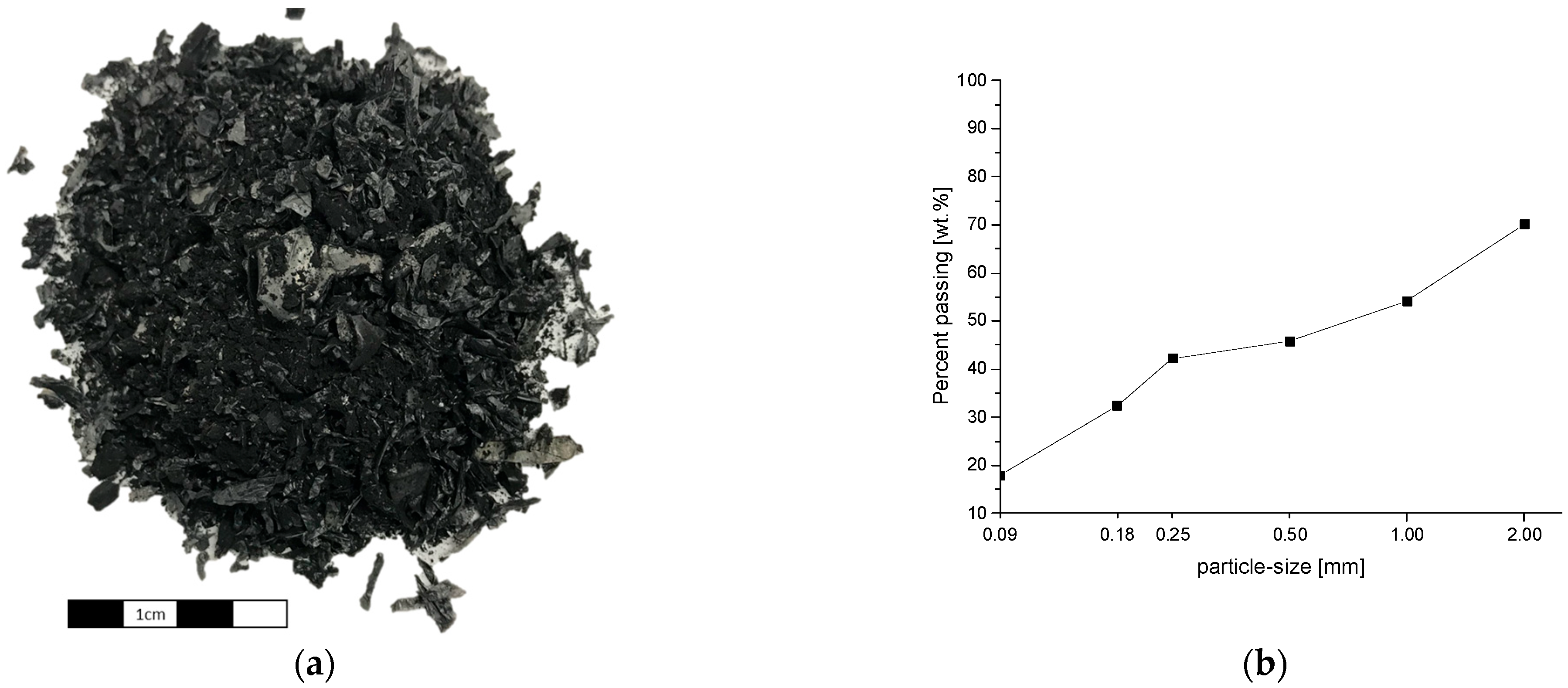
In the following sections, the input material, the experimental procedure and the intended analytics are presented.

2.1. Used Materials

For the thermal treatment trials, inert shredded NMC 622 LIBs were used. The shredder was provided dried below 100 °C and under a slight vacuum. Figure 1a shows a picture of the material, and Figure 1b shows the mass-related particle-size distribution of the material.
In total, 30.0 wt.% of the material does not pass the 2 mm sieve; 45.8% is smaller than 0.5 mm and can therefore be classified as active mass. Changes in this particle-size distribution after the thermal treatment could give information on the delamination of the copper and aluminum foils and are, therefore, important indicators for the success of the process.
Each particle-size fraction was analyzed for its chemical composition, summarized in Table 2. Analysis was carried out by ICP-OES (Spectro CIROS Vision, Spectro Analytical Instruments GmbH, Kleve, Germany), ion chromatography (811 Compact IC pro, Deutsche Metrohm GmbH & Co. KG, Filderstadt, Germany) and combustion method (ELTRA CS 2000, ELTRA GmbH, Haan, Germany). The Cu and Al values are to be understood as guide values, as the different size fractions of the material can lead to inaccuracies in sampling and analyzing the foil fractions. Nevertheless, the analysis is in good agreement with Peschel et al. [35], who carried out a detailed characterization of the same shredder material.

2.2. Thermal Treatment Trials

Thermal treatment trials were carried out in a resistance-heated furnace. A cylindrical steel bomb of 19 L volume with a water-cooled lid is placed inside of it. The water cooling is necessary to protect the rubber sealings of the lid from the heat and, therefore, ensure gas tightness during the process. Two thermocouples and a lance for gas injection are inserted through the lid. One of the thermocouples is placed in the center of the cylinder and inside the material. The material itself is placed inside a dense sintered alumina crucible. To prevent material losses through the exhaust gas pipe, the crucible is placed inside a second 2.5 L steel chamber with a labyrinth system for the exhaust gas. The exhaust gas is fed via a pipe heated to 350 °C (avoidance of condensation) to a two-stage scrubber. The first one is filled with NaOH solution to remove halogens like fluorine. Simultaneously, high-boiling organics are condensed. The second scrubber is filled with water and serves for post-cleaning. After scrubbing, the gas is fed to a thermal post-combustion to crack organic compounds. The setup is schematically shown in Figure 2.
The experiments were carried out under an Ar atmosphere with a constant flow rate of 14 L/min. After inertization, the furnace was heated with 300 °C/h to the desired temperature between 376 and 719 °C. The holding time varied between 15 and 115 min.
After the end of the holding time, the heating of the furnace was shut off, and the material remained in the furnace until it reached room temperature to prevent oxygen contact at elevated temperatures. The gas flow was turned off at a material temperature < 200 °C to avoid water entry in the reactor due to pressure loss during cooling.
For determining the off-gas composition, additional experiments in a smaller scale with 10 g of LIB shredder were carried out in a 3 L furnace chamber with a similar set-up as the large-scale trials and an adjusted N2-flow of 2.5 l/min. In contrast to the large-scale trials, N2 is used for these measurements to cope with the calibration of the FTIR (Fourier-transform infrared spectroscopy) analyzer. A total of 2 L/min of the off-gas was transferred through the lid of the reactor and through a heated hose via a pump (ASYCO) to the FTIR (DX 400, Gasmet Technology Oy, Vantaa, Finland). The whole system is heated to 180 °C to prevent condensation of gas components. However, it must be considered that the lid of the reactor is water-cooled and, therefore, some high boiling gas components may not reach the analysis system due to condensation at the lid.
A part of the pumped gas is fed to a condensing pump, which cools the gas down to 5 °C for drying, and afterwards to an oxygen (Oxygen Analyzer PMA 10, M&C TechGroup, Ratingen, Germany) and hydrogen analyzer (CONTHOS 3—TCD, LFE GmbH & Co. KG, Bruchköbel, Germany) with compensation of CO2 and O2. The measurement results were analyzed with the Calcmet Analysis software, version 12.210.
A sieve classification of the thermally treated material from the 200 g scale trials was carried out in a manner similar to that of the input material. Afterwards, an XRD analysis (Bruker D8 Advance, Cu Kα 0.154 nm) of the <90 µm fraction, as well as an elemental analysis of the <500 µm fraction (similar to the input material), was performed on a selection of samples. Additionally, the <90 µm fraction of selected pyrolyzed samples with similar holding times (ca. 30 min) but different treatment temperatures under Ar atmosphere were analyzed by pyrolysis-GC-MS (PY-3030D pyrolizer, Frontier Laboratories) for remaining organics after the thermal treatment. Therefore, the samples were carried in a pyrolysis chamber preheated to 515 °C under He. The emitted gases were analyzed via GC-MS (QP2010 Ultra, Shimadzu, Japan, separation column Ultra ALLOY-5(MS/HT), 30 m × 0.25 mm × 0.25 µm; Sigma Aldrich) as described in [35]. This analysis was carried out by MEET-Münster Electrochemical Energy Technology.
Water leaching tests to recover lithium and to investigate the fluorine and phosphorous removal were carried out with all <500 µm samples. The experimental procedure is described in Section 2.3.

2.3. Water Leaching Trials

The leaching of the material fractions <500 µm was carried out in a 1 L glassware beaker. The 20 g samples were mixed with 500 mL deionized water and stirred at 200 rpm for 90 min. During the trials, five 5 mL samples of the liquid were taken to investigate the influence of leaching time on the dissolution behavior of the contained elements. The samples were taken after 2, 5, 15, 60 and 90 min. For complete mass balance calculations, the trials were carried out without interim sampling, too. The solution was analyzed by ICP-OES for the metals contained (see above) and for fluorine with ion selective electrode (Metrohm Titrando 888, Deutsche Metrohm GmbH & Co. KG). Moreover, the inorganic carbon content was determined by a TOC analyzer (multi N/C 2100/2100S, Analytik Jena GmbH, Jena, Germany) and, in case of interim sampling, with an ion-selective electrode regarding Li (ISE, Mettler Toledo, DX207-Li, for samples after 15 and 60 min).
After 90 min, the solution was filtrated. The filter cake was washed with 200 mL of deionized water and dried at 80 °C.
The lithium-containing solution is evaporated at temperatures of approximately 90 °C to recover the salts. The salts were dried at RT for 72 h. This could lead to residual moisture. The purity of the salt product was determined by ICP-OES and IC, and the phase composition was determined by XRD analysis.

3. Results and Discussion

The results and discussion of the thermal treatment trials and the following lithium recovery, dependent on the thermal treatment parameters, are provided in the following sections.

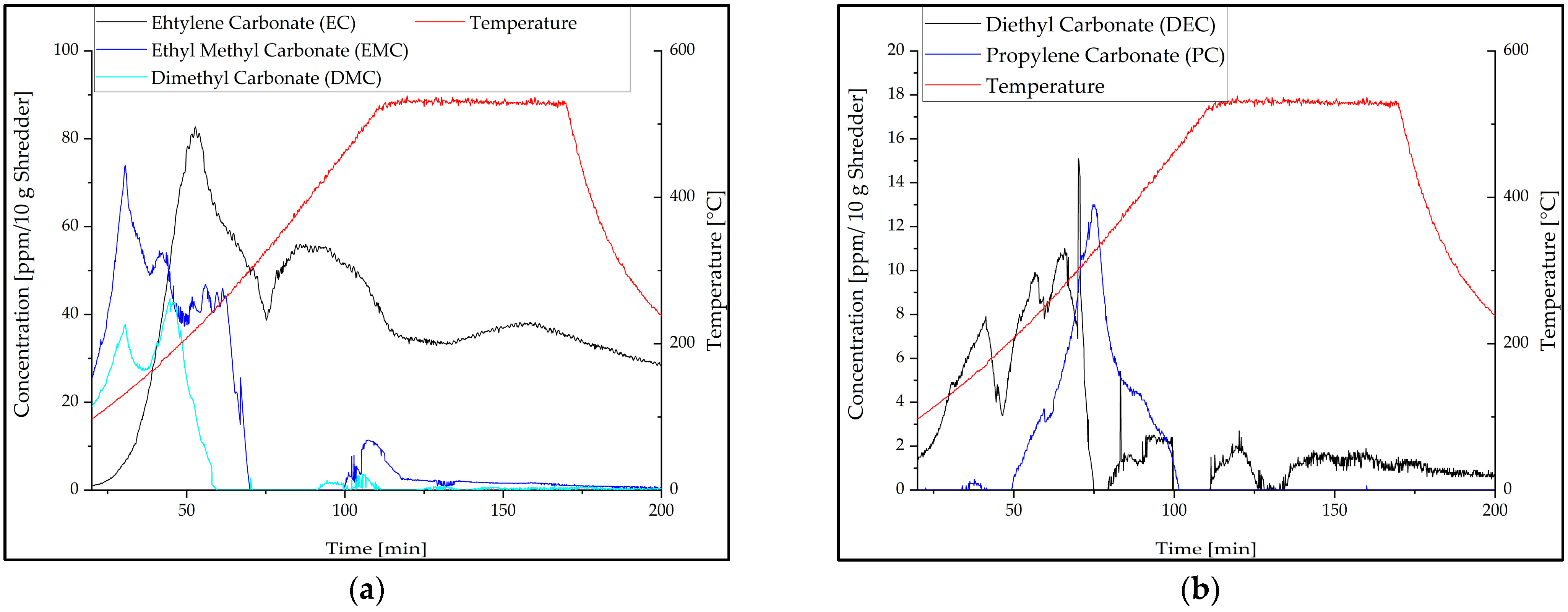
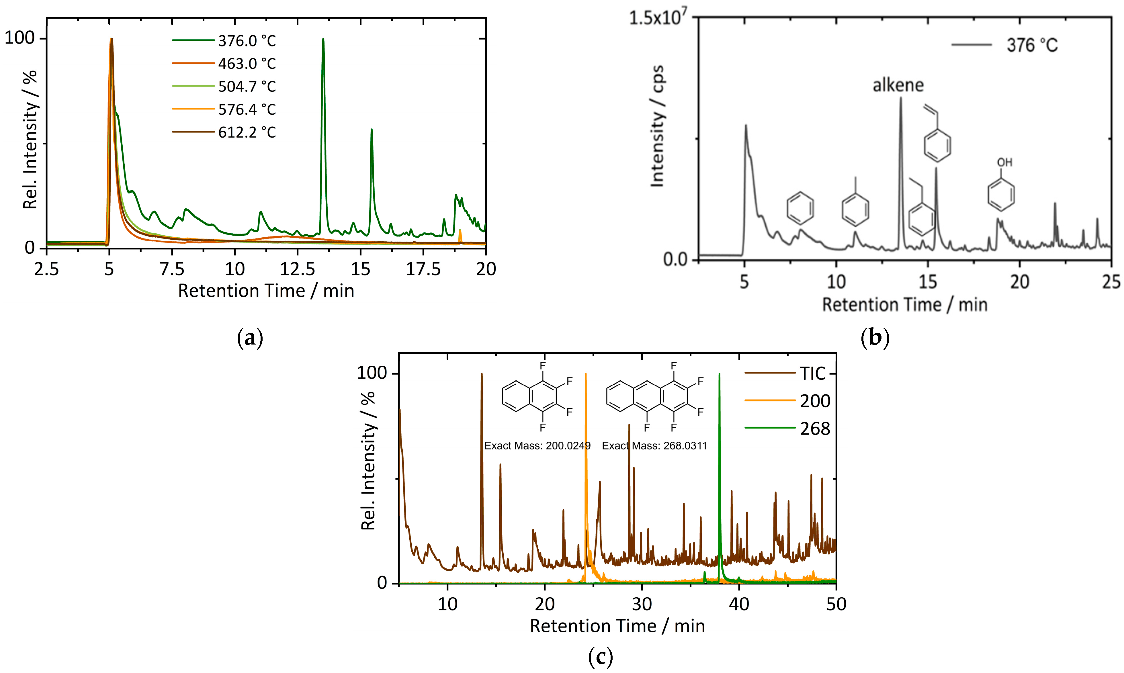
3.1. Off-Gas Analysis during Pyrolysis

During pyrolysis, the release of electrolyte compounds was measured by FTIR analysis. Since the off-gas has a quite complex composition, limitations of the analysis method, as described in a previous study [30], have to be taken into account.
The main components, according to Figure 3, are ethylene carbonate (EC) and ethyl methyl carbonate (EMC) since they are detectable in the highest concentration of up to 80 ppm/10 g shredder. Even though the shredded material was provided dried, the low boiling [9] components DMC, EMC and diethyl carbonate (DEC) were detectable from the beginning of the trials due to their high vapor pressure. EC and PC are released at higher temperatures, according to their higher boiling points (246 °C and 242 °C) [9], and reach their peaks at 220 °C (EC) and 325 °C (PC). EC is the only component continuously measured during the whole trial. It has the highest boiling point of 246 °C [9], so it can condensate at the water-cooled lid of the furnace and also in the FTIR system, which is heated to 180 °C. The constant release of the condensate could lead to its measurement during the whole trial. Since PC is present in significantly lower quantities in the material, this phenomenon is not occurring for it.
In addition to the electrolyte compounds, CO, CO2 and hydrocarbons make up a large share of the produced off-gas. CO2 release is observed within four peaks, as shown in Figure 4a. The first peak is observed at 180 °C and is related to the thermal decomposition of the solid electrolyte interphase (SEI) and LiPF6. The reaction of LiPF6 to LiF and PF5 by thermal degradation, which is reported for the pure compound in the temperature range of 177–277 °C [37], enables reaction (3) [38] with CO2 release.
Li 2 CO 3 +   PF 5     2 LiF   +   POF 3 +   CO 2
The simultaneous detection of POF3 at 180 °C, shown in Figure 5, is in accordance with the described reactions. Additionally, further CO2-releasing reactions of electrolyte components could be possible and will be discussed in detail in a future study.
At around 320 °C, the second CO2 peak is detected. Simultaneously, POF3 and hydrocarbons are released, and the concentration of DEC, EC and EMC drops. This leads to the conclusion of starting decomposition reactions of organics. Since the cracking of organics, e.g., the electrolyte and CMC binder, can result in the release of H2O [39,40,41], HF is measurable at 300 °C. Reactions of LiPF6 and its decomposition product POF3 with moisture lead to HF formation according to Equations (4)–(7) [42,43].
LiPF 6 +   H 2 O     LiF   +   POF 3 + 2 HF
POF 3 + H 2 O     POF 2 OH +   HF
POF 2 OH + H 2 O     POF ( OH ) 2 +   HF
POF ( OH ) 2 +   H 2 O     H 3 PO 4 +   HF
Most of the pyrolysis reactions, which means organic decomposition, take place at around 500 °C with the largest peak of hydrocarbons. It is followed by the largest peak of HF at around 530 °C, according to the decomposition of the binder PVDF [44,45]. Furthermore, during the holding time at 530 °C, the largest CO2 peak followed by CO release is measured. At this time, the hydrocarbon concentration has already dropped to low concentrations, which leads to the assumption of carbon reactions with metal oxides during the holding time. Reducing reactions with carbon will lead to CO2 and CO release and are further addressed in Section 3.3.
A detailed investigation of the gas evolution and reaction mechanisms will be published in a future study by the authors.

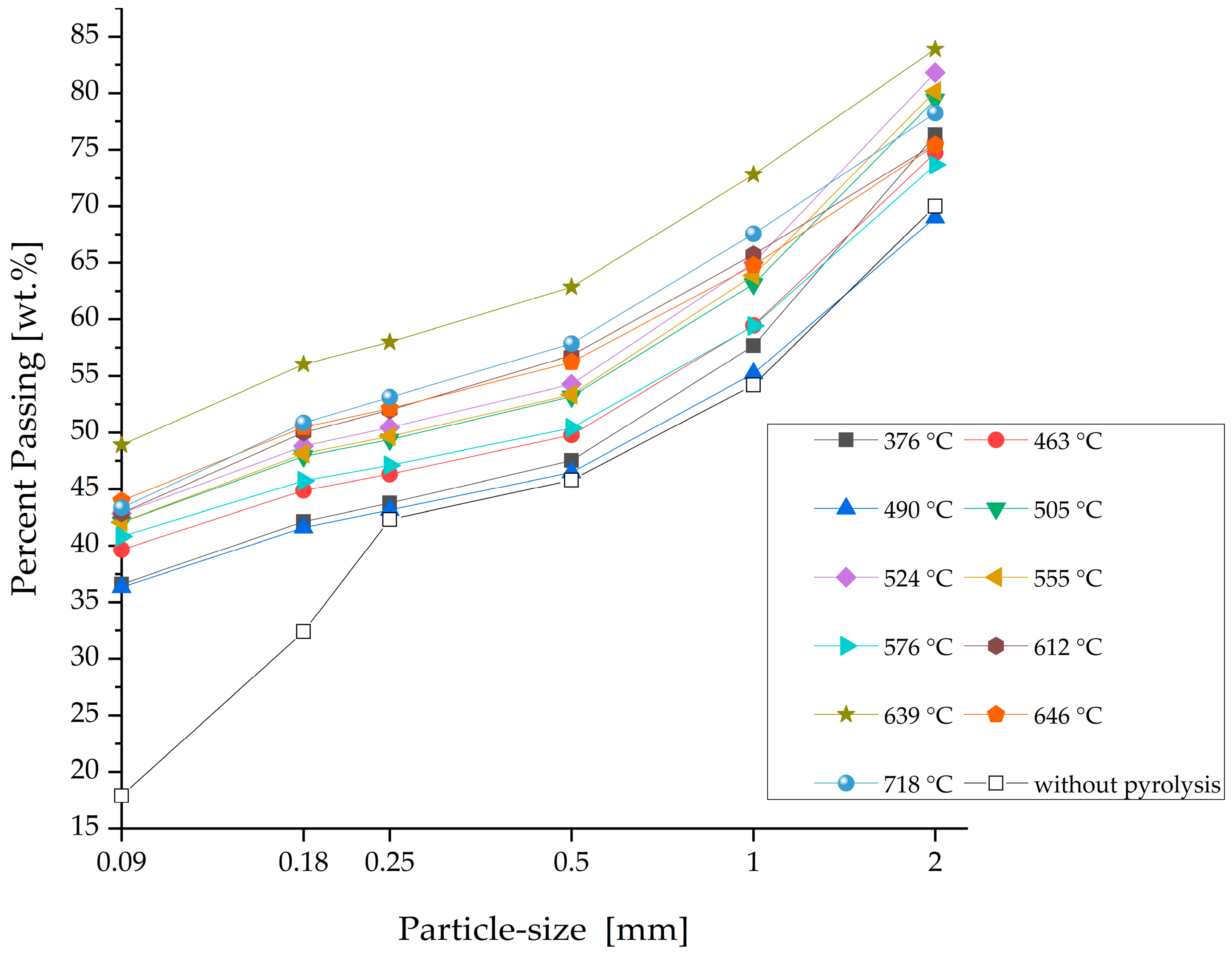
3.2. Weight Loss and Particle Size Distribution after Pyrolysis

After pyrolysis, the shredder was weighed. Figure 6 shows the percentage weight loss related to the maximum temperature and the holding time during pyrolysis. The black dots mark the direct experimental results given in Table A1. Based on them, the slope was calculated by interpolation after the Thin Plate Spline method. It shows that mass loss rises with temperature and holding time, but the temperature has a larger impact. Over temperature, the slope of the curve differs. The steepest incline of the slope and, therefore, most of the mass loss with up to 11% occurs in the temperature range between around 450 °C and 580 °C. This relates to the temperature-dependent decomposition of individual battery components and the described off-gas measurement (see Section 3.1). Hydrocarbon release starts at around 400 °C and reaches its maximum at 500 °C. Moreover, the decomposition of the binder PVDF, accompanied by HF release (see Figure 5) [44,45], starts at around 500 °C (see Section 3.1). With further increases in temperature, phase changes of cathode material (see Section 3.3) with CO2 release (see Figure 4a) take place so that there is still a detectable rising mass loss. In total, it amounts to 16.75% at 719 °C.
An additional analysis of the samples already pyrolyzed at different temperatures but with the same holding times of 30 min by pyrolysis-GC-MS measurement proves the presence of remaining organics in the sample pyrolyzed at 376.0 °C. As shown in Figure 7b, mainly aromatic, especially phenolic molecules are identified. Furthermore, alkane and alkene are present. A closer look at the fingerprint area of the spectrum shows that the binder PVDF is still present after pyrolysis. The thermal degradation of PVDF results in the formation of aromatic fluorinated compounds [44,45]. Fluorinated decomposition products with the specific masses 200 and 268 are shown in Figure 7c and are clearly detectable in the spectrum. In comparison, the sample pyrolyzed at 463.0 °C shows just a slightly increased intensity at a retention time of 12.5 min, shown in Figure 7a, indicating organic residues. In the samples pyrolyzed at higher temperatures (504.7 °C and above), organics are no longer detectable. These results fit well with the above-described mass loss behavior of the material during pyrolysis. However, it has to be considered that the pyrolysis-GC-MS measurement was carried out at 500 °C, so the conclusion is limited to the complete removal of all organic components decomposed and volatile up to this temperature. However, it proves that the holding time of ~30 min during the pyrolysis trials is sufficient for organic removal.
Furthermore, the particle-size distribution of the pyrolyzed battery shredder can indicate binder removal and the delamination of collector foils. Therefore, it differs according to the pyrolysis parameters. In Figure 8, it can be seen that a pyrolysis temperature of 376 °C led to a higher percentage of the fine fractions smaller than 0.09 and 0.18 mm compared to the untreated material. Contained organics from the electrolyte and binder cause the sticking of active mass particles and hinder the delamination of the collector foils. Except for the untreated material, the curves show similar characteristics but are shifted in parallel to higher passing percentages with pyrolysis temperature. Lombardo et al. [8] observed a similar behavior for the delamination of pure cathode foil production scrap after thermal treatment between 450 and 650 °C, but without giving a grain size distribution. Exceptions of the trend in the present study are the samples treated at 646.3 and 717.9 °C. These curves lie under the sample treated at 638.5 °C. This is due to the agglomeration of metals and active mass during the trials close to and above the melting point of aluminum (660 °C) [9].

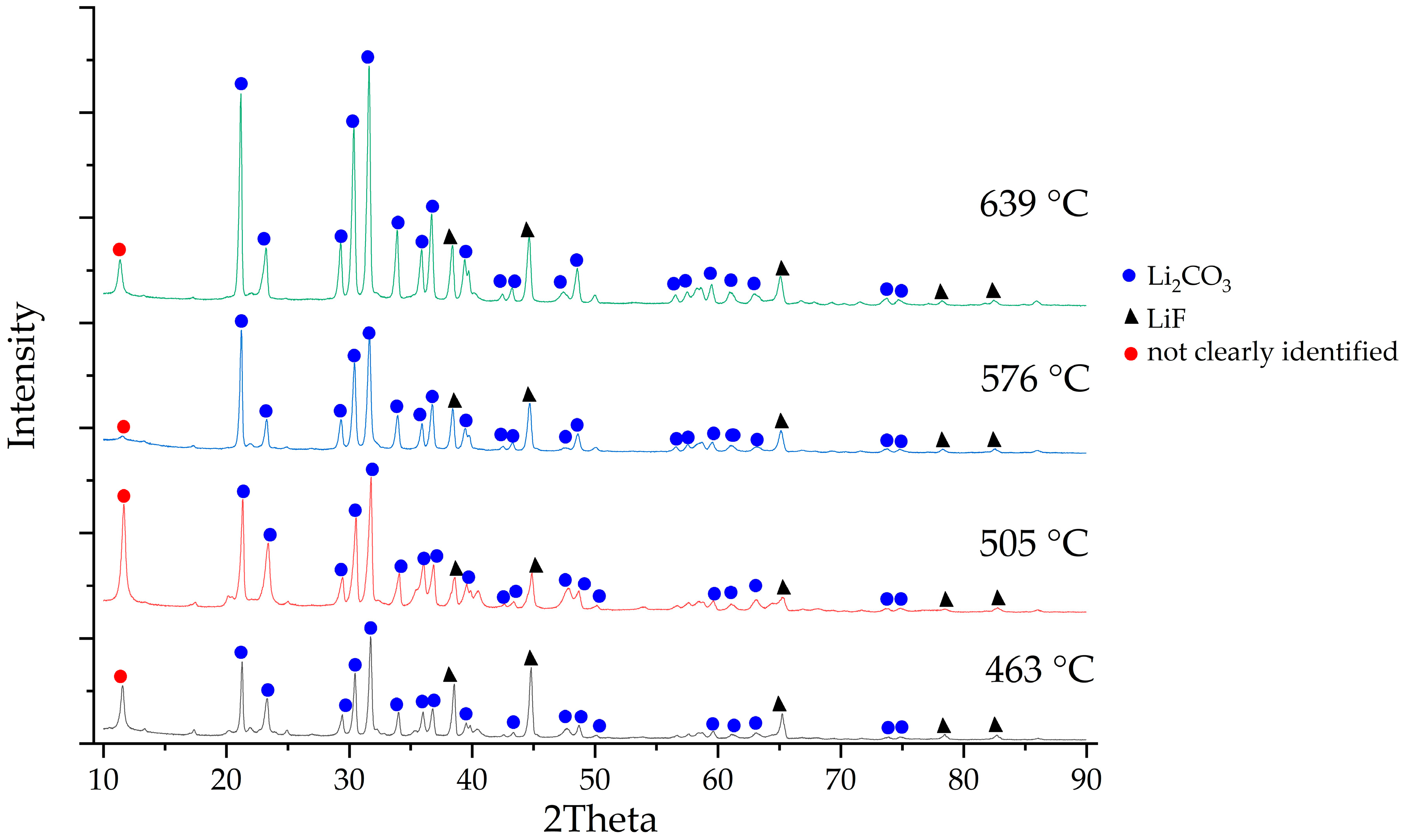
3.3. XRD Analysis of Pyrolyzed Active Mass

XRD analysis of the generated black mass fractions from the pyrolyzed shredder, presented in Figure 9, shows different phases depending on the thermal treatment temperature. The NMC oxides are increasingly reduced as the temperature rises. First, NMC is reduced to simpler mixed oxides such as LNCO until at around 500 °C single NiO and Co2O3 are detectable. In this sample, also the reduction reaction product Li2CO3 is detected for the first time. But lithium-metal-oxides still exist, which means that the lithium is not completely liberated at 500 °C. Further increase of the temperature results in the reduction of NiO to Ni as well as of the mixed Li-containing metal oxides to, e.g., MnO and CoO and Li2CO3. This is confirmed by the rising intensity of Li2CO3 reflexes in the XRD pattern with temperature. Additionally, Li3PO4 is detectable in the sample treated at 576 °C. The trend towards a more complete reduction of metal oxides with temperature is in general accordance with the literature, but in contrast to a study with dismantled NMC 111 batteries, the XRD in the present study shows more complete reduction reactions. Balachandran et al. [20] did not identify metallic Ni in their XRD pattern, which might be due to the lower Ni-containing NMC material and the sample preparation without shredding. Shredding leads to the mixing of the battery compounds and, therefore, possibly better interaction of metal oxides with reducing agents. Also, the larger material amount in the furnace and the higher bulk height might contribute to a better reduction of metal oxides due to longer contact times of the reducing gases with the solid material in the present study.
During the pyrolysis process, different reaction partners are possible for the described reduction reactions. On the one hand, the material contains graphite, but a TGA/DTA analysis of mixtures of pure battery graphite with NMC622 shows no mass loss until ~720 °C (see Supplementary Material Figure S1). More favorable are reactions of the metal oxides with gaseous pyrolysis products or coke. Related to the described off-gas analysis in Section 3.1, possible reaction partners could be CO and CH4.
Next to NMC and lithium, the aluminum phases are of special interest regarding further treatment steps like water leaching. Already, the untreated black mass fraction from the battery shredder contains Al2O3. The sample treated at around 576 °C shows reflexes of AlF3. Equilibrium calculations with the equilib model of FactSageTM 8.0 [46] show that the following reactions are possible starting from 455 °C:
Al   + 3 HF     AlF 3 + 1.5   H 2
Al 2 O 3 + 6   HF     2 AlF 3 +   H 2 O
Figure 9. XRD analysis of black mass samples from battery shredder thermally treated at different temperatures for 30–40 min.
Metals 13 02000 g009

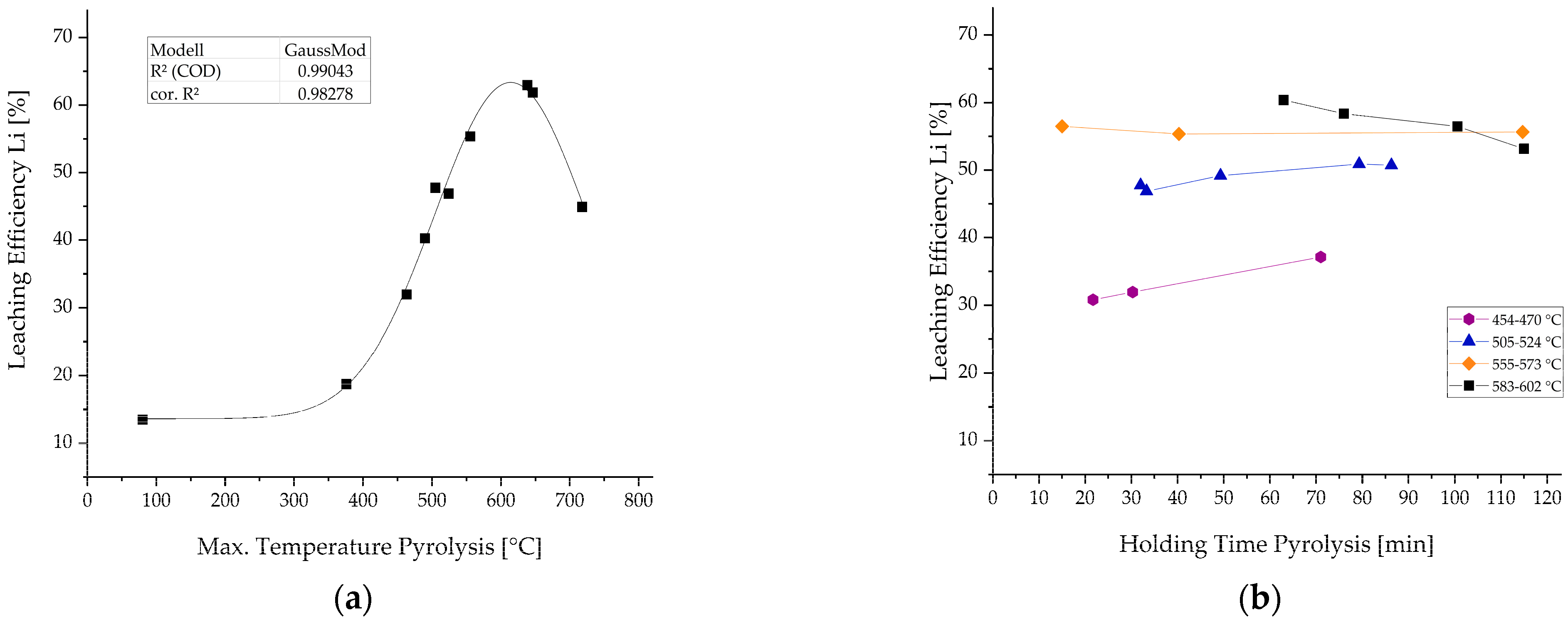
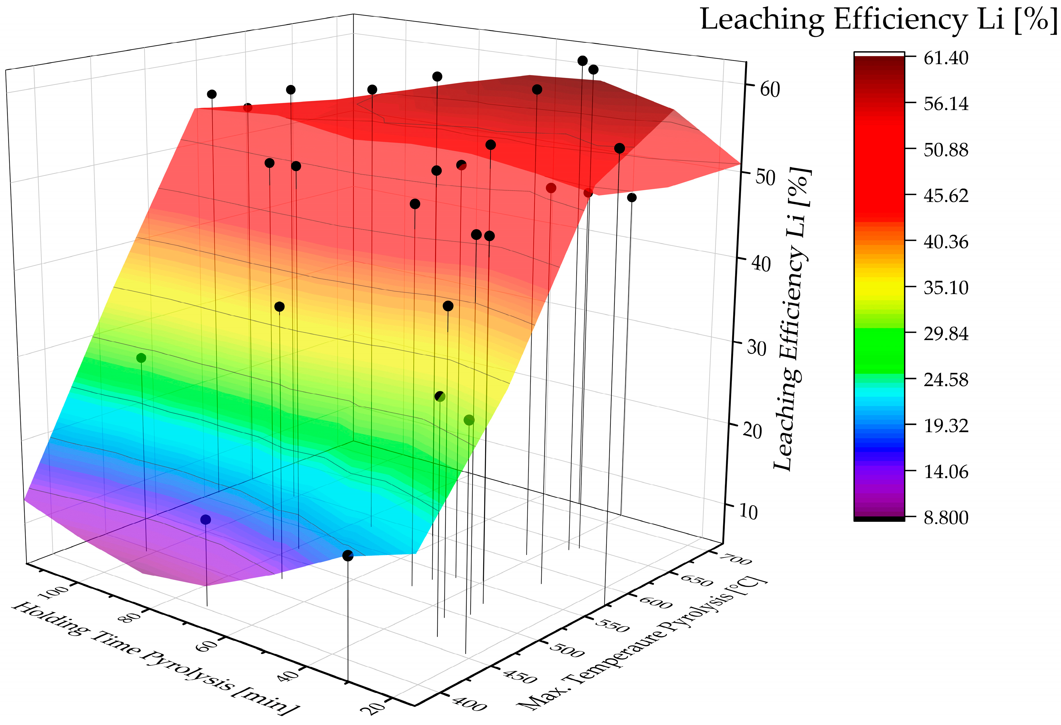
3.4. Results of Water Leaching Trials

The leaching efficiency LE of lithium in water, calculated after Equation (10), was investigated depending on pyrolysis temperature and holding time.
LE L i = L i   i n   s o l u t i o n   g   L i   i n p u t   t o   w a t e r   l e a c h i n g   g × 100 %
Figure 11a shows the results of the leaching trials depending on the maximum reached temperature during pyrolysis with a similar holding time between 30 and 40 min. Until 375 °C, the thermal treatment shows no significant influence on the leachability of the lithium content in water. Afterwards, a nearly linear increase in LE with pyrolysis temperature is observed. The best LE achieved experimentally is 62.4%, with a pyrolysis temperature of around 642 °C. Further temperature increases lead to a decrease in LE. The course of the LE in the investigated temperature range can be described with a GaussMod Fit, as shown in Figure 11a. This course can be explained by the temperature-dependent reactions taking place during the pyrolysis process. As presented in Figure 9, the reduction reactions of the NMC result in the liberation of lithium as Li2CO3 with rising temperatures. The complete decomposition of the NMC oxides is necessary for maximum solubility of the lithium content. Moreover, the removal of binders and other organics supports leachability, as the particles get into direct contact with water. However, exceeding the melting point of aluminum during thermal treatment has a negative effect. The partial melting of the material (Figure 10) causes clumping of the fine fraction and, therefore, reduces leachability. Therefore, the optimum temperature based on the applied model for maximum LE of 63 °% Li is 614 °C.
In comparison to the huge effect of pyrolysis temperature, the holding time (Figure 11b) shows no great influence on the lithium LE, especially in the elevated temperature ranges from 500 to 570 °C. In higher temperature ranges around 600 °C, longer holding times result in a slight decrease in the leachability of lithium. This may be caused by slow reactions of lithium with aluminum to insoluble lithium aluminates, which were found in a study by Hu et al. [13] to be formed between 650 and 900 °C. In contrast, longer holding times in lower temperature ranges between 454 and 470 °C seem to be favorable for higher LE. However, due to the experimental setup, exact temperature adjustment was not possible during the pyrolysis trials. This leads to the given temperature ranges in which the holding times are compared with each other. Especially in the low-temperature range, the difference of 16 °C could have a higher influence on the results than the holding time, which makes the interpretation difficult in this case.
For a more holistic investigation and interpretation of the influence of pyrolysis parameters on the leachability of lithium, Figure 12 shows a 3D plot with a modeled surface for all recorded data points. This modeling confirms the significantly greater influence of pyrolysis temperature compared to holding time on the lithium recovery. Balachandran et al. [20] and Roquette et al. [21] found a similar correlation between the pyrolysis parameters and the LE of lithium for NMC material.
Three studies in the literature with manually dismantled NMC 111 battery cells achieved similar maximum LE for Li of 60% [20], 62% [21] and 64% [3]. Other reviewed studies in Table 1 showed higher LE for Li of up to 98.93% [31] but for different input materials such as synthetic black masses and LCO cathode material. This indicates a significant influence of the chemical composition and accompanying elements of the input material. The presence of F, Al and P in the industrial shredder material leads to the formation of the nearly insoluble Li-bearing compounds LiF, Li3PO4 and LiAlO2 as described above, e.g., by reactions of already formed Li2CO3 with HF according to Equation (11) [46,47]:
Li 2 CO 3 + 2 HF     2 LiF   + H 2 O   +   CO 2

3.5. Lithium Leaching over Time

To further investigate the leaching behavior of Li, additional leaching trials were carried out with sampling over time. The leaching of Li is quick, so in most cases, the largest amount of Li (up to 98% of final Li concentration) is already dissolved after 15 min, as shown in Figure 13. Afterwards, just a slight increase in Li concentration is measured. This indicates that the accessibility of formed water-soluble Li-compounds for the leachate is not dependent on the given range of thermal treatment parameters. Roquette et al. found similar kinetic behavior for their lower Ni-containing NMC material.

3.6. Leaching Behavior of Other Battery Elements

The analysis of the leaching solution regarding further battery elements besides lithium did not reveal any detectable contents of cobalt, nickel, manganese and copper. However, the solution contains significant amounts of aluminum and fluorine (Figure 14). In the case of dried material at 80 °C, just 83 mg/L F is detectable due to the dissolution of F-containing salts. With rising pyrolysis temperature, more F-containing salts, especially LiF, are released during the thermal treatment (see sections above) and leached afterwards, but no clear trend according to pyrolysis temperatures above 375 °C can be determined. Due to the complexity of F analysis, the deviation is estimated to be 10%. The theoretical possible maximum F amount in water from LiF is not reached in any of the trials. It remains to be clarified if this is due to accompanying elements and the basic pH value of the solution.
In the case of Al, there seems to be a trend of rising Al co-extraction with rising pyrolysis temperature, but three trials are not consistent and have significantly larger Al concentrations in the solution. Due to the overall small Al amount in the solution, variations in the input feed may have a significant influence on the leaching behavior. However, the general trend towards enhanced leaching of Al with rising temperature, and, as described with rising Li extraction, is explained by the basic pH value (10–11) of the leach solution due to dissolved Li2CO3. This causes Al corrosion in accordance with the Pourbaix diagram of Al [46,48]. Additionally, AlF3 formation has been shown in some XRD patterns (see Figure 9), which has a water-solubility of 5 g/L [9]. Shorter leaching times could result in less Al leaching and will, therefore, lead to a Li-salt product with a higher purity.
In addition to the co-extraction of further battery elements, the inorganic carbon (IC) in solution was determined. Figure 15 shows a plot of IC concentration in comparison with Li concentration in the leach solution depending on the previous pyrolysis temperature. Both graphs have a similar course, where the concentration rises rapidly above 375 °C and is nearly linear. Both curves reach a maximum but at different temperatures of 572 °C (IC) and 614 °C (Li). It was expected that the curves would be parallel because the Li in the solution mainly originates from Li2CO3, and F-leaching is nearly constant. Possible explanations could be necessary improvements in the new application of IC measurement in battery recycling and sample stability. Moreover, Li could be present in solution either as carbonate or as hydrogen carbonate, resulting in different IC concentrations. But overall, both curves show good agreement in the observed trends. Therefore, IC measurement in solution is a promising tool to evaluate the Li2CO3 content of a black mass sample.

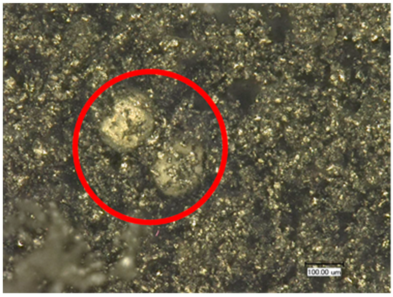
3.7. Characterization of Salt Product

The salt products were characterized by XRD analysis regarding the present phases. In all analyzed samples, the main components are Li2CO3 and LiF, as can be seen from Figure 16. With rising pyrolysis temperature, a rising intensity of the Li2CO3 reflexes is observed. This is consistent with the observed correlation between rising Li-leaching and IC concentration with pyrolysis temperature. The elemental analysis of the salt, given in Table 3, confirms Li and F as the main elements in the salt (a carbon analysis was not carried out). Previous studies also identified Li2CO3 and LiF as the main components of the salt product, but, e.g., Balachandran et al. [20] found a higher share of LiF than Li2CO3 in their product after water leaching of pyrolyzed black mass due to leaching at elevated temperatures of 80 °C. In comparison, Rouquette et al. [21] had similar results regarding the identified phases in the XRD analysis of lower Ni-containing LIB material compared to this study.
Additionally, Al, which was already identified in the leach solution, is present in the salt product in a range of 1.99–4.36 wt.%. In all XRD patterns, a reflex at 11.6 2 Theta is present, which cannot be clearly identified, but Al-P-compounds are a possibility.
Further minor impurities in the salt are S and Na, and in the samples treated at 463 °C and 505 °C, P is detected (see Table 3). P could originate from the decomposition products of the conducting salt LiPF6 and small amounts of dissolved Li3PO4, which was detected in some XRD patterns of the black mass and has a slight water solubility of 0.27 g/L [9]. It could have formed by the reaction of Li2CO3 with phosphoric acid, which is formed during the decomposition of LiPF6 according to Equation (7). Traces of S and Na were detected by Peschel et al. [35] in the input shredder material as well and are explained to originate from S-containing electrolyte additives and CMC binders applied as sodium salt. Those minor impurities have not been addressed in previous studies but state the influence of low share battery components on product purity in the recycling chain.

4. Conclusions

The thermal pre-treatment of spent LIB battery shredder is a powerful tool to condition the material for further processing. Therefore, it is of high importance to evaluate the impact of the process parameters on the solid and gaseous products. This study investigated the influences of temperature and holding time during the thermal treatment under Ar for an industrially produced NMC 622 shredder material in a more enhanced scale than is known in the literature. The continuous off-gas measurement shows different main gas release periods, which are associated with the boiling points of electrolyte components and decomposition reactions of organics. The PVDF binder decomposes as one of the last organic compounds above 500 °C with HF release. Additional pyrolysis GC-MS measurements of the thermally treated black mass confirmed necessary temperatures above 500 °C for an organic removal as complete as possible. This is again reflected in the sieve analysis of the shredder after the thermal treatment, where the removal of organics and especially binders contributes to the delamination of collector foils and leads to higher black mass yields, but temperatures above the aluminum melting point have a disadvantageous effect, as they lead to material clumping.
The temperature-dependence of NMC metal-oxides reduction reported in the literature is confirmed by XRD analysis in this study for NMC 622 as well. Ni has been reduced to a metallic state, and the NMC reflexes are no longer detectable above 500 °C. Due to the presence of all battery compounds in contrast to studies regarding artificial material mixtures, the black mass has a complex phase composition, so phosphates and fluorides are detected in some samples. This phase composition of the black mass has a direct impact on the LE in the ESLR water leaching trials. The more NMC is reduced, the more Li2CO3 is available for leaching. Therefore, the LE of Li and of inorganic carbon increase with pyrolysis temperature. A Gaussian correlation between LE and pyrolysis temperature was established for the first time in the parameter range investigated. The 3D interaction with the holding time during pyrolysis shows only a slight influence of the holding time on the LE, particularly in low-temperature ranges. In ESLR, the main co-extracted elements from batteries are F and Al due to the presence of LiF and the basic pH value of the leach solution. Accordingly, they are present in the final Li-salt product. Furthermore, traces of Na, S and P originating from Li3PO4, electrolyte additives, and binder are present. These co-elements, especially F, Al and P, and their behavior during pyrolysis, have a significant influence on Li recovery in water leaching. Even after the complete reduction of Li-metal oxides, a maximum LE of 62.4% is achieved. The formation of Li-compounds with low water-solubility, such as LiF, Li3PO4 and LiAlO2, limits the Li recovery and explains the differences compared to some previous studies in literature treating artificial black mass.

Supplementary Materials

The following supporting information can be downloaded at: https://www.mdpi.com/article/10.3390/met13122000/s1, Figure S1: TGA/DTA analysis of a mixture of pure NMC 622 and graphite.

Author Contributions

Conceptualization, C.S.; methodology, C.S.; validation, C.S.; formal analysis, C.S.; investigation, C.S.; resources, C.S.; data curation, C.S.; writing—original draft preparation, C.S.; writing—review and editing, C.S. and B.F.; visualization, C.S.; supervision, B.F.; project administration, C.S. and B.F.; funding acquisition, C.S. and B.F. All authors have read and agreed to the published version of the manuscript.

Funding

This research was funded by the German Federal Ministry of Education and Research (BMBF) in the frame of the project “InnoRec”, grant number 03XP0246D.

Data Availability Statement

The data presented in this study are available in this article and related Supplementary Material.

Acknowledgments

The authors acknowledge all project partners for their support. The authors would especially like to thank Christoph Peschel and Sascha Nowak for carrying out the pyrolysis GC-MS and XRD measurements and the chemical analysis of the precipitated Li-salts.

Conflicts of Interest

The authors declare no conflict of interest. The funders had no role in the design of the study, in the collection, analyses, or interpretation of data, in the writing of the manuscript, or in the decision to publish the results.

Appendix A

Table A1. Weight Loss related to pyrolysis parameters.
Max. Temperature Pyrolysis [°C]Holding Time Pyrolysis [min]Weight Loss [%]
555.340.311.79
489.534.811.13
572.61511.41
612.24214.33
534.748.312.4
454.321.711.32
547.345.312.21
52433.313.59
46330.39.84
576.430.712.75
593.8100.613.1
583.17612.84
518.286.311.5
518.279.310.74
517.349.311.38
469.87111.06
504.73211.2
638.53715.95
646.33614.89
37630.28.61
7195116.75
717.94016.34
597.76314.24
563.8114.712.94
601.611513.35
403.672.69.15
445.6101.79.69

References

  1. Brückner, L.; Frank, J.; Elwert, T. Industrial Recycling of Lithium-Ion Batteries—A Critical Review of Metallurgical Process Routes. Metals 2020, 10, 1107. [Google Scholar] [CrossRef]
  2. Pinegar, H.; Smith, Y.R. Recycling of End-of-Life Lithium Ion Batteries, Part I: Commercial Processes. J. Sustain. Metall. 2019, 5, 402–416. [Google Scholar] [CrossRef]
  3. Schwich, L.; Schubert, T.; Friedrich, B. Early-Stage Recovery of Lithium from Tailored Thermal Conditioned Black Mass Part I: Mobilizing Lithium via Supercritical CO2-Carbonation. Metals 2021, 11, 177. [Google Scholar] [CrossRef]
  4. Harper, G.D.J.; Kendrick, E.; Anderson, P.A.; Mrozik, W.; Christensen, P.; Lambert, S.; Greenwood, D.; Das, P.K.; Ahmeid, M.; Milojevic, Z.; et al. Roadmap for a sustainable circular economy in lithium-ion and future battery technologies. J. Phys. Energy 2023, 5, 21501. [Google Scholar] [CrossRef]
  5. Hanisch, C. Recycling Method for Treating Used Batteries, in Particular Rechargeable Batteries, and Battery Processing Installation. U.S. Patent Application No. 2017076113, 12 October 2017. [Google Scholar]
  6. Primobius GmbH Process and Technology. Available online: https://www.primobius.com/process-technology (accessed on 3 April 2022).
  7. Yang, Y.; Huang, G.; Xu, S.; He, Y.; Liu, X. Thermal treatment process for the recovery of valuable metals from spent lithium-ion batteries. Hydrometallurgy 2016, 165, 390–396. [Google Scholar] [CrossRef]
  8. Lombardo, G.; Ebin, B.; Steenari, B.-M.; Alemrajabi, M.; Karlsson, I.; Petranikova, M. Comparison of the effects of incineration, vacuum pyrolysis and dynamic pyrolysis on the composition of NMC-lithium battery cathode-material production scraps and separation of the current collector. Resour. Conserv. Recycl. 2021, 164, 105142. [Google Scholar] [CrossRef]
  9. Haynes, W.M. CRC Handbook of Chemistry and Physics: A Ready-Reference Book of Chemical and Physical Data, 97th ed.; CRC Press: Boca Raton, FL, USA; London, UK; New York, NY, USA, 2017; ISBN 978-1-4987-5429-3. [Google Scholar]
  10. Zhang, G.; Du, Z.; He, Y.; Wang, H.; Xie, W.; Zhang, T. A Sustainable Process for the Recovery of Anode and Cathode Materials Derived from Spent Lithium-Ion Batteries. Sustainability 2019, 11, 2363. [Google Scholar] [CrossRef]
  11. Petranikova, M.; Miskufova, A.; Havlik, T.; Vojtko, M. Recovery of Cobalt and Lithium from Spent Portable Lithium Accumulators After Incineration. In Proceedings of the Kammel’s Quo Vadis Hydrometallurgy, Herlany, Slowakia, 4–7 June 2012; pp. 155–162. [Google Scholar]
  12. Vieceli, N.; Casasola, R.; Lombardo, G.; Ebin, B.; Petranikova, M. Hydrometallurgical recycling of EV lithium-ion batteries: Effects of incineration on the leaching efficiency of metals using sulfuric acid. Waste Manag. 2021, 125, 192–203. [Google Scholar] [CrossRef]
  13. Hu, J.; Zhang, J.; Li, H.; Chen, Y.; Wang, C. A promising approach for the recovery of high value-added metals from spent lithium-ion batteries. J. Power Sources 2017, 351, 192–199. [Google Scholar] [CrossRef]
  14. Liu, P.; Xiao, L.; Tang, Y.; Chen, Y.; Ye, L.; Zhu, Y. Study on the reduction roasting of spent LiNixCoyMnzO2 lithium-ion battery cathode materials. J. Therm. Anal. Calorim. 2019, 136, 1323–1332. [Google Scholar] [CrossRef]
  15. Yue, Y.; Wei, S.; Yongjie, B.; Chenyang, Z.; Shaole, S.; Yuehua, H. Recovering Valuable Metals from Spent Lithium Ion Battery via a Combination of Reduction Thermal Treatment and Facile Acid Leaching. ACS Sustain. Chem. Eng. 2018, 6, 10445–10453. [Google Scholar] [CrossRef]
  16. Diaz, F.; Wang, Y.; Weyhe, R.; Friedrich, B. Gas generation measurement and evaluation during mechanical processing and thermal treatment of spent Li-ion batteries. Waste Manag. 2019, 84, 102–111. [Google Scholar] [CrossRef]
  17. Lombardo, G.; Ebin, B.; Foreman, M.R.S.J.; Steenari, B.-M.; Petranikova, M. Incineration of EV Lithium-ion batteries as a pretreatment for recycling—Determination of the potential formation of hazardous by-products and effects on metal compounds. J. Hazard. Mater. 2020, 393, 122372. [Google Scholar] [CrossRef] [PubMed]
  18. Sun, L.; Qiu, K. Vacuum pyrolysis and hydrometallurgical process for the recovery of valuable metals from spent lithium-ion batteries. J. Hazard. Mater. 2011, 194, 378–384. [Google Scholar] [CrossRef] [PubMed]
  19. Makuza, B.; Tian, Q.; Guo, X.; Chattopadhyay, K.; Yu, D. Pyrometallurgical options for recycling spent lithium-ion batteries: A comprehensive review. J. Power Sources 2021, 491, 229622. [Google Scholar] [CrossRef]
  20. Balachandran, S.; Forsberg, K.; Lemaître, T.; Vieceli, N.; Lombardo, G.; Petranikova, M. Comparative Study for Selective Lithium Recovery via Chemical Transformations during Incineration and Dynamic Pyrolysis of EV Li-Ion Batteries. Metals 2021, 11, 1240. [Google Scholar] [CrossRef]
  21. Rouquette, L.M.; Lemaître, T.; Vieceli, N.; Petranikova, M. Intensification of lithium carbonation in the thermal treatment of spent EV Li-ion batteries via waste utilization and selective recovery by water leaching. Resour. Conserv. Recycl. Adv. 2023, 17, 200125. [Google Scholar] [CrossRef]
  22. Wang, J.-P.; Pyo, J.-J.; Ahn, S.-H.; Choi, D.-H.; Lee, B.-W.; Lee, D.-W. A Study on the Recovery of Li2CO3 from Cathode Active Material NCM(LiNiCoMnO2) of Spent Lithium Ion Batteries. J. Korean Powder Metall. Inst. 2018, 25, 296–301. [Google Scholar] [CrossRef]
  23. Vishvakarma, S.; Dhawan, N. Recovery of Cobalt and Lithium Values from Discarded Li-Ion Batteries. J. Sustain. Metall. 2019, 5, 204–209. [Google Scholar] [CrossRef]
  24. Xiao, J.; Li, J.; Xu, Z. Recycling metals from lithium ion battery by mechanical separation and vacuum metallurgy. J. Hazard. Mater. 2017, 338, 124–131. [Google Scholar] [CrossRef]
  25. Xiao, J.; Li, J.; Xu, Z. Novel Approach for in Situ Recovery of Lithium Carbonate from Spent Lithium Ion Batteries Using Vacuum Metallurgy. Environ. Sci. Technol. 2017, 51, 11960–11966. [Google Scholar] [CrossRef]
  26. Zhang, G.; He, Y.; Feng, Y.; Wang, H.; Zhu, X. Pyrolysis-Ultrasonic-Assisted Flotation Technology for Recovering Graphite and LiCoO 2 from Spent Lithium-Ion Batteries. ACS Sustain. Chem. Eng. 2018, 6, 10896–10904. [Google Scholar] [CrossRef]
  27. Zhu, L.; Chen, M. Development of a Two-Stage Pyrolysis Process for the End-Of-Life Nickel Cobalt Manganese Lithium Battery Recycling from Electric Vehicles. Sustainability 2020, 12, 9164. [Google Scholar] [CrossRef]
  28. Lombardo, G.; Ebin, B.; Foreman, M.R.S.J.; Steenari, B.-M.; Petranikova, M. Chemical Transformations in Li-Ion Battery Electrode Materials by Carbothermic Reduction. ACS Sustain. Chem. Eng. 2019, 7, 13668–13679. [Google Scholar] [CrossRef]
  29. Lombardo, G. Effects of Pyrolysis and Incineration on the Chemical Composition of Li-Ion Batteries and Analysis of the By-Products; Chalmers University of Technology Nuclear Chemistry/Industrial Materials Recycling: Göteborg, Sweden, 2019. [Google Scholar]
  30. Stallmeister, C.; Friedrich, B. Influence of Flow-Gas Composition on Reaction Products of Thermally Treated NMC Battery Black Mass. Metals 2023, 13, 923. [Google Scholar] [CrossRef]
  31. Li, J.; Wang, G.; Xu, Z. Environmentally-friendly oxygen-free roasting/wet magnetic separation technology for in situ recycling cobalt, lithium carbonate and graphite from spent LiCoO2/graphite lithium batteries. J. Hazard. Mater. 2016, 302, 97–104. [Google Scholar] [CrossRef] [PubMed]
  32. Noh, H.-J.; Youn, S.; Yoon, C.S.; Sun, Y.-K. Comparison of the structural and electrochemical properties of layered Li[NixCoyMnz]O2 (x = 1/3, 0.5, 0.6, 0.7, 0.8 and 0.85) cathode material for lithium-ion batteries. J. Power Sources 2013, 233, 121–130. [Google Scholar] [CrossRef]
  33. Stallmeister, C.; Schwich, L.; Friedrich, B. Early-Stage Li-Removal—Vermeidung von Lithiumverlusten im Zuge der Thermischen und Chemischen Recyclingrouten von Batterien. In Recycling und Rohstoffe; Holm, O., Thomé-Kozmiensky, E., Goldmann, D., Friedrich, B., Eds.; Thomé-Kozmiensky Verlag GmbH: Neuruppin, Germany, 2020; pp. 544–557. ISBN 978-3-944310-51-0. [Google Scholar]
  34. Wang, H.; Friedrich, B. Development of a Highly Efficient Hydrometallurgical Recycling Process for Automotive Li–Ion Batteries. J. Sustain. Metall. 2015, 1, 168–178. [Google Scholar] [CrossRef]
  35. Peschel, C.; van Wickeren, S.; Preibisch, Y.; Naber, V.; Werner, D.; Frankenstein, L.; Horsthemke, F.; Peuker, U.; Winter, M.; Nowak, S. Comprehensive Characterization of Shredded Lithium-Ion Battery Recycling Material. Chemistry 2022, 28, e202200485. [Google Scholar] [CrossRef] [PubMed]
  36. Bernd, F.; Christin, S.; Claudia, S.; Lilian, P. Process Alternatives for Li-Recovery from Spent Batteries. Copenhagen. 2019. Available online: https://www.researchgate.net/publication/336086375_Process_Alternatives_for_Li-recovery_from_spent_batteries (accessed on 3 April 2022).
  37. Gravritchev, K.S.; Sharpataya, G.A.; Smagin, A.A.; Malyi, E.N.; Matyukha, V.A. Calorimetric study of thermal decomposition of lithium hexafluorophosphate. J. Therm. Anal. Calorim. 2003, 73, 71–83. [Google Scholar] [CrossRef]
  38. Weber, N.; Schuhmann, S.; Tübke, J.; Nirschl, H. Chemical Thermal Runaway Modeling of Lithium-Ion Batteries for Prediction of Heat and Gas Generation. Energy Technol. 2023, 11, 2300565. [Google Scholar] [CrossRef]
  39. Lamb, J.; Orendorff, C.J.; Roth, E.P.; Langendorf, J. Studies on the Thermal Breakdown of Common Li-Ion Battery Electrolyte Components. J. Electrochem. Soc. 2015, 162, A2131–A2135. [Google Scholar] [CrossRef]
  40. Kriston, A.; Adanouj, I.; Ruiz, V.; Pfrang, A. Quantification and simulation of thermal decomposition reactions of Li-ion battery materials by simultaneous thermal analysis coupled with gas analysis. J. Power Sources 2019, 435, 226774. [Google Scholar] [CrossRef]
  41. Jakab, E.; Mészáros, E.; Borsa, J. Effect of slight chemical modification on the pyrolysis behavior of cellulose fibers. J. Anal. Appl. Pyrolysis 2010, 87, 117–123. [Google Scholar] [CrossRef]
  42. Tebbe, J.L.; Fuerst, T.F.; Musgrave, C.B. Mechanism of hydrofluoric acid formation in ethylene carbonate electrolytes with fluorine salt additives. J. Power Sources 2015, 297, 427–435. [Google Scholar] [CrossRef]
  43. Stich, M.; Göttlinger, M.; Kurniawan, M.; Schmidt, U.; Bund, A. Hydrolysis of LiPF 6 in Carbonate-Based Electrolytes for Lithium-Ion Batteries and in Aqueous Media. J. Phys. Chem. C 2018, 122, 8836–8842. [Google Scholar] [CrossRef]
  44. de Jesus Silva, A.J.; Contreras, M.M.; Nascimento, C.R.; Da Costa, M.F. Kinetics of thermal degradation and lifetime study of poly(vinylidene fluoride) (PVDF) subjected to bioethanol fuel accelerated aging. Heliyon 2020, 6, e04573. [Google Scholar] [CrossRef] [PubMed]
  45. O’shea, M.L.; Morterra, C.; Low, M. Spectroscopic studies of carbons. XVII. Pyrolysis of polyvinylidene fluoride. Mater. Chem. Phys. 1990, 26, 193–209. [Google Scholar] [CrossRef]
  46. Bale, C.W.; Bélisle, E.; Chartrand, P.; Decterov, S.A.; Eriksson, G.; Gheribi, A.E.; Hack, K.; Jung, I.H.; Kang, Y.B.; Melançon, J.; et al. FactSage Thermochemical Software and Databases, 2010–2016. Calphad 2016, 54, 35–53. [Google Scholar] [CrossRef]
  47. Freiberg, A.T.; Sicklinger, J.; Solchenbach, S.; Gasteiger, H.A. Li2CO3 decomposition in Li-ion batteries induced by the electrochemical oxidation of the electrolyte and of electrolyte impurities. Electrochim. Acta 2020, 346, 136271. [Google Scholar] [CrossRef]
  48. Leisegang, T.; Meutzner, F.; Zschornak, M.; Münchgesang, W.; Schmid, R.; Nestler, T.; Eremin, R.A.; Kabanov, A.A.; Blatov, V.A.; Meyer, D.C. The Aluminum-Ion Battery: A Sustainable and Seminal Concept? Front. Chem. 2019, 7, 268. [Google Scholar] [CrossRef] [PubMed]
Figure 1. (a) A photograph and (b) the particle-size distribution by mass of the untreated LIB shredder.
Metals 13 02000 g001
Figure 2. The experimental setup for the thermal treatment experiments [36].
Metals 13 02000 g002
Figure 3. The concentration of electrolyte components (a) EC, EMC and DMC and (b) DEC and PC over time during pyrolysis under N2 in small-scale experiments with 10 g LIB shredder, exemplary for one temperature and holding time.
Metals 13 02000 g003
Figure 4. The concentration of (a) CO and CO2 and (b) the sum of hydrocarbons over pyrolysis time in small-scale experiments under N2 with 10 g LIB shredder, exemplary for one temperature and holding time.
Metals 13 02000 g004
Figure 5. The concentration of HF and POF3 over pyrolysis time in small-scale experiments under N2 with 10 g LIB shredder, exemplary for one temperature and holding time.
Metals 13 02000 g005
Figure 6. Weight loss of battery shredder related to maximum pyrolysis temperature and holding time (t(Tmax)+/−t(Tmax−20 °C)) for Ar pyrolysis (Matrix modelling: Thin Plate Spine interpolation with five columns and seven lines) and experimental data points (black dots).
Metals 13 02000 g006
Figure 7. The pyrolysis-GC-MS measurement of the <90 µm fraction of pyrolyzed samples: (a) comparison of GC-MS results for samples pyrolyzed at different temperatures; (b) detailed organic analysis of the sample pyrolyzed at 376 °C; (c) the fingerprint of PVDF decomposition products compared to total ion chromatogram of the sample pyrolyzed at 376 °C.
Metals 13 02000 g007
Figure 8. The particle-size distribution of pyrolyzed battery shredder depending on pyrolysis temperature for a holding time of 30–40 min.
Metals 13 02000 g008
Figure 10. A light microscope image of a <500 µm fraction from the pyrolysis trial at 718 °C with molten particles.
Metals 13 02000 g010
Figure 11. The leaching efficiency of lithium after water leaching (<500 µm fraction; 40 g/L; 90 min) depending on (a) maximal temperature during pyrolysis with a holding time between 30 and 40 min and (b) holding time during pyrolysis for different temperature ranges.
Metals 13 02000 g011
Figure 12. The leaching efficiency of lithium after water leaching (<500 µm fraction; 40 g/L; 90 min) depending on pyrolysis temperature and holding time (Matrix modelling: Thin Plate Spine interpolation with five columns and seven lines) and experimental data points (black dots).
Metals 13 02000 g012
Figure 13. Li in solution depending on leaching time for different previous thermal treatment temperatures and holding times.
Metals 13 02000 g013
Figure 14. Co-extraction and concentration of (a) fluorine and (b) aluminum in solution after 90 min water-leaching of black mass from thermally treated LIB shredder under Ar for 30–40 min depending on pyrolysis temperature.
Metals 13 02000 g014
Figure 15. A comparison between Li and inorganic carbon content (IC) in solution after 90 min water-leaching of black mass samples from LIB shredder treaded at different pyrolysis temperatures for 30–40 min under Ar.
Metals 13 02000 g015
Figure 16. XRD pattern of lithium salts depending on maximum pyrolysis temperature with a holding time of 30–40 min.
Metals 13 02000 g016
Table 1. Overview of previous studies regarding Li-recovery from thermally treated battery materials (best results).
Input MaterialExperimental ParametersResultsSource
Spent NMC cathode
active material
Heating and cooling under Ar atmosphere,
holding at 800 °C under CO2 atmosphere
for 2 h
88.97% Li recovered[22]
Water leaching: 33.33 g/L, 5 h
Spent NMC cathode
active material,
addition of lignite
500–900 °C under Ar atmosphere for 3 h,
Addition of lignite: 25.2%,
Water leaching: 20 g/L, 2 h,
LE (Li)500 °C: 74.6%
LE (Li)650 °C: 89.4%
LE (Li)900 °C: 55.3%
[13]
Pure LiCoO2 + graphite
(4:3)
Oxygen-free roasting at 1000 °C for 30 min
under N2
Wet magnetic separation in H2O,
5 g/L, 48 h; 20 °C
LE (Li)1000 °C: 98.93%[31]
Spent LIBs
(not specified)
Oxygen-free roasting at 1000 °C for 30 min
under N2
Wet magnetic separation in H2O:
5 g/L, 48 h; 20 °C
LE (Li)1000 °C: 70.43%[31]
active mass < 53 µm of shredded LCO LIBs
(organics burned at 450 °C for 30 min)
Atmospheric heat treatment 500–900 °C for
5–45 min under air,
Water leaching: 50 g/L, 30 min
Best reduction at 900 °C, 15 min (XRD),
6 g Li2CO3 out of 100 g LIBs, no LE or recovery rate given
[23]
Active mass from spent
and shredded LMO LIBs
Oxygen-free roasting at 800 °C, for 45 min,
Enclosed vacuum
Water leaching: 10 g/L, 20–30 min
Li recovery in form of Li2CO3: 91.3%[24]
NMC battery cellsThermal treatment of battery cells at
  • 509 °C and 603 °C under Ar,
  • at 501 °C under Ar + 5% O2,
  • at 466 °C under CO2
Investigation of different water leaching
parameters of active mass fraction < 1 mm
Higher Li-yields for higher temperature in thermal treatment,
Best result:
Li-Yield (Carbonate)603 °C: 64% (33 g/L, 120 min, washed filter cake)
[3]
Cathode, anode and
separator foil from
NMC 111 cells
Thermal treatment: pyrolysis, incineration,
pyrolysis + coke at different temperatures
from 400 to 700 °C for 30–90 min
Water leaching: 100 g/L and 200 g/L, for 3 h,
at RT and 80 °C
Higher LE for higher temperature and pyrolysis, no effect of coke
Best result:
LE (Li)700 °C pyrolysis for 60 min; 200 g/L at 80 °C 3 h: 60%
[20]
Different spent NMC cathode material + cokeThermal treatment 500–650 °C, for
15–120 min under Ar,
Coke addition 7.5–20%
Water leaching: 33.33 g/L for 1 h at RT
Best Li-yields for roasting at 650 °C for 30 min and coke addition of 10%
LE(Li)650 °C, 30 min, 10% coke: 93.67%
[14]
Spent NMC battery cells, manually dismantled, with and without separatorThermal treatment 400–700 °C for 30–90 min
under Ar and air
Water leaching: 20 g/L for 1 min to 3 h at RT
Best Li-yields for pyrolysis with separator, at 700 °C for 60 min
LE (Li)700 °C, 60 min, with separator: 62%
[21]
Spent batteries of type
LMO,
LCO,
NMC
Vacuum pyrolysis of each separated active
mass at 600–1000 °C for 15–90 min,
Water leaching 50 and 25 g/L
Best Li-yields with 50 g/L
LE (Li)700 °C, 30 min, LMO: 81.9%
LE (Li)700 °C, 30 min, LCO: 82.7%
LE (Li)700 °C, 30 min, NMC: 66.3%
[25]
Table 2. The composition of the battery shredder in wt.%, analyzed by ICP-OES, combustion and ion chromatography (IC).
CompoundLiTiMnSCoNiCuAlSiPZrFC
MethodICP-OESICComb.
Mean2.510.014.260.194.5614.204.515.040.110.570.153.5134.55
Table 3. The chemical composition of precipitated Li-salts in wt.% depending on the maximal temperature during pyrolysis with a holding time of 30–40 min.
Max. Temperature Pyrolysis [°C]LiAlFSNaP
46316.094.3619.011.190.610.27
50513.826.626.010.860.450.16
57617.312.3012.940.700.430.00
63916.782.328.400.440.340.00
64617.041.996.890.510.400.00
Disclaimer/Publisher’s Note: The statements, opinions and data contained in all publications are solely those of the individual author(s) and contributor(s) and not of MDPI and/or the editor(s). MDPI and/or the editor(s) disclaim responsibility for any injury to people or property resulting from any ideas, methods, instructions or products referred to in the content.

