Article

Evaluation of the Influence Exerted by Increased Silicon Contents on the Leaching Behavior of NMC-Based Black Mass

Chair of Nonferrous Metallurgy, Montanuniversität Leoben, 8700 Leoben, Austria
*
Author to whom correspondence should be addressed.
Metals 2023, 13(4), 785; https://doi.org/10.3390/met13040785
Submission received: 27 March 2023 / Revised: 11 April 2023 / Accepted: 12 April 2023 / Published: 17 April 2023

Abstract

:
The further development of lithium-ion batteries leads to an improvement in power densities as well as safety and thus requires an optimization of the materials used. For this purpose, among other approaches, the anode materials are doped with silicon oxide or metallic silicon is used as the anode. However, silicon is a semimetal and is known to lead to the formation of jelly-like fluids in hydrometallurgical processes under certain conditions. This publication evaluates which parameters are responsible for this viscosity change in the leaching solutions during the recycling of lithium-ion batteries and examines the corresponding reaction mechanism behind this phenomenon. Furthermore, the leaching efficiency for the valuable metals nickel, cobalt, lithium and manganese is evaluated and the influence of different silicon contents in the solution is investigated. It could be shown that, especially the simultaneous presence of H2SO4, H2O2 and Si or SiO2, lead to a significant viscosity increase due to the formation of metasilicic acid and, accordingly, the leaching efficiencies of the valuable metals are negatively influenced.

1. Introduction

Hydrometallurgy is a field of metallurgy that deals with the recovery of metals from ores and secondary materials using water-based solutions. One of the challenges in this field is the presence of silicon, which can interfere with the recovery of certain metals by forming insoluble compounds. This can lead to decreased efficiency and increased costs in the metal recovery process.
The pure crystalline silicon (alpha-silicon) forms dark grey, opaque, very shiny, hard, brittle octahedra with a density of 2.368 g·cm−3. In addition to the form of silicon that is stable under standard conditions, several high-pressure modifications of this element are known. The forms available under increasing pressure show increasing densities (see Figure 1) [1,2].
Silicon reacts exothermically (+339.5 kJ) with water to form silicon dioxide and hydrogen (see Equation (1)) [3].
Si + 2   H 2 O   SiO 2 + 2   H 2  
However, silicon is practically insoluble in all acids, despite its strongly negative normal potential (−0.909 V), since the SiO2, which is insoluble in acid and formed primarily by the action of water according to Equation (1), prevents further attack by the acid. In contrast, silicon dissolves easily and exothermically in hot alkalis that are capable of attacking SiO2, forming silicate and hydrogen (see Equation (2)) [1,3].
SiO 2 + 2   OH   SiO 3 2 + H 2 O
The same applies to hydrofluoric acid containing HNO3, in which the stable SiF62− complex is formed. The effect of temperature on the solubility of amorphous silica can be seen in Figure 2 [4,5].
Amorphous silica, also known as silica gel or colloidal silica, is a form of silicon dioxide that exists in an amorphous (non-crystalline) state. It is a highly porous and highly reactive material that is used in a wide range of applications, including catalysis, adsorption, and separation processes. The chemical composition of amorphous silica is typically represented as SiO2, and it is formed by the polymerization of silica tetrahedra, which are units composed of a central silicon atom surrounded by four oxygen atoms. The properties of amorphous silica can be tailored by varying the synthesis conditions, such as pH, temperature, and reactant concentrations. Amorphous silica has a high surface area due to its porous structure, and it can be modified with various chemical groups, such as hydroxyl, carboxyl, and amino, which can affect its properties, such as reactivity and adsorption capacity [2,3,6].
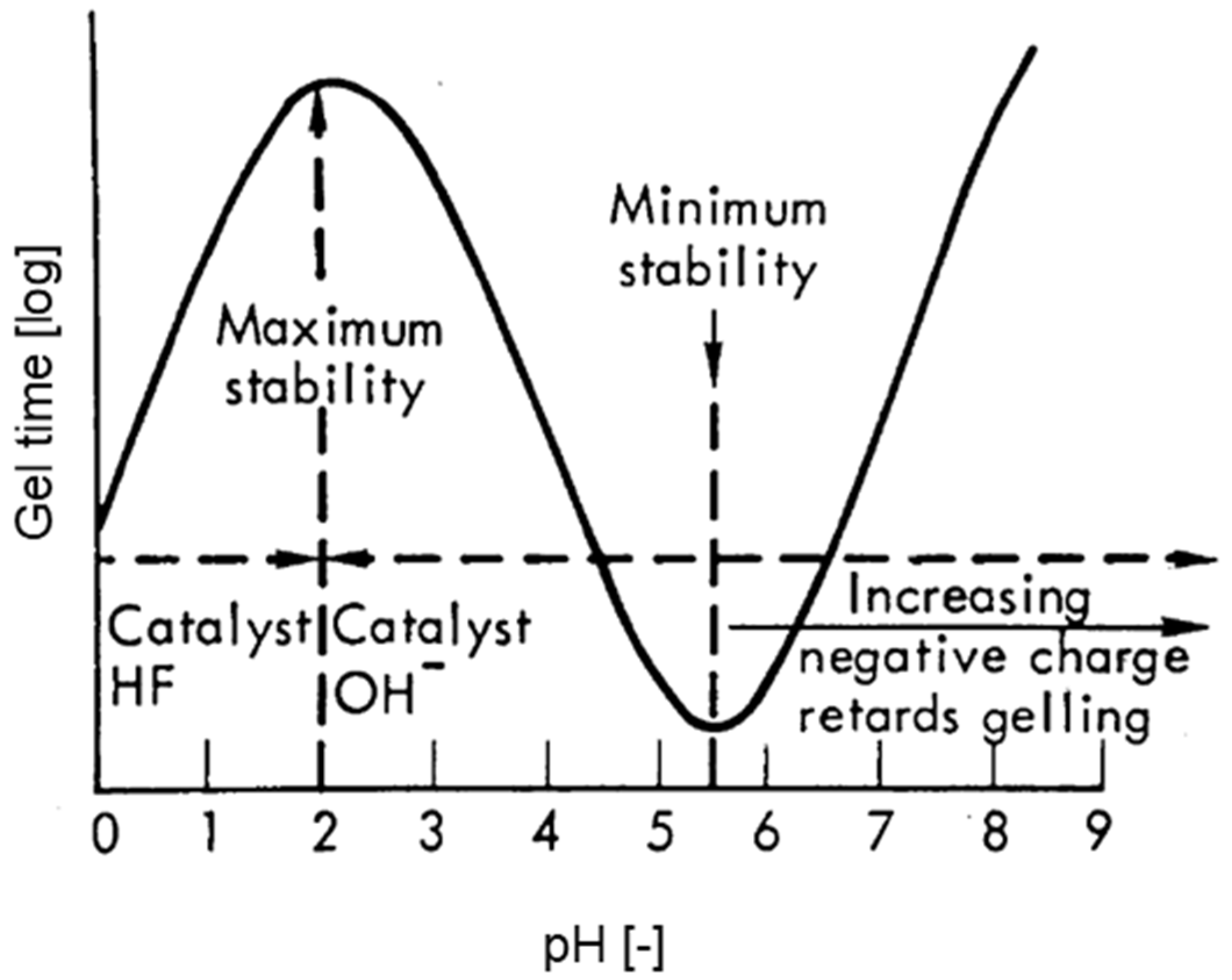
Silicon generally forms a tetrahedrally constructed oxygen-containing ion of the composition EO4n−, the silicate ion (monosilicate, SiO44−) [7]. It is derived from the relatively weak, quadribasic silicon acid H4SiO4 (orthosilicic acid), the simplest member of the silicic acids. Monosilicic acid has a great tendency to split off water (exothermic process). The solubility of the silicic acids decreases in parallel with the increase in the size of the molecule when water is released. Therefore, if the solution of an orthosilicate is acidified, the solution initially remains clear, and then—depending on its concentration, more or less rapidly—gelatinises to a jelly. Accordingly, in the salts of silicic acids that are formed, there are usually silicate anions that are combined into larger complexes by means of the associated metal cations (often magnesium, calcium, aluminium or iron ions). In all of these silicates, the silicon has the coordination number 4: each silicon atom is tetrahedrally surrounded by four oxygen atoms, whereby the SiO4 tetrahedra are corner-linked via common O-atoms. The pH has an important influence on the gelating behavior, as the rate of colloid aggregation is changed. The colloid particles are negatively charged in alkaline solutions and are thus hindered from coagulating. By the addition of soluble salts, the situation is changed and gelation is likely. In acidic solution (below pH 2) the colloidal particles are positively charged and therefore hardly influenced by other cations in the solution. As shown in Figure 3, the region of maximum stability occurs and the colloidal particles exhibit neither a positive nor a negative charge. In this field, the probability of rapid agglomeration is nevertheless low, but increases proportionally with the OH concentration above pH 2. The maximum agglomeration or gelling rate occurs in a pH range of 5 to 8, as the negative charge of the colloidal particles exceeds the catalytic effect of the increasing OH concentration. The described behavior can be seen in Figure 3 [1,2,3,7].
The presence of silicon in acidic solutions can have an impact on the stability of other metals, can cause corrosion, and can affect the efficiency of certain chemical reactions. Some acidic solutions can be used to dissolve silicon compounds, such as silicon carbide (SiC), in order to obtain silicon, but this process is not simple and requires multiple steps. The behavior of silicon in acidic solutions might vary depending on the specific conditions (concentration of acid, pH, presence of other elements, temperature, etc.) and the type of silicon compound [3,6].
When amorphous silicon is dissolved in an acidic solution, it can exist in different forms, depending on the pH and the concentration of acid. At low pH values, silicon exists in the form of silicic acid (H4SiO4), while at higher pH values, it exists as silicate ions (SiO32−). The solubility of silicon in acidic solutions is relatively low, and increases with decreasing pH [3].
In summary, silicon can affect hydrometallurgical processes in a number of ways, including [4,5,8,9]:
  • By forming insoluble compounds with certain metals, such as aluminum and iron, which can decrease the recovery efficiency of these metals.
  • By acting as a reducing agent, which can reduce the oxidation state of certain metals, making them less accessible to the recovery process.
  • By precipitating as silica, which can clog the process equipment and decrease the overall efficiency of the recovery process.
  • By complicating the purification and separation steps of the recovery process, as silicon compounds can be difficult to separate from those of the desired metal.
  • By decreasing the selectivity of certain recovery agents, such as cyanide, which can lead to the recovery of unwanted metals in addition to the desired one.
  • By increasing the reagent consumption due to formation of silicate and silica which need to be removed by using reagents such as caustic soda, lime, etc.
The presence of silicon from anode material in the leachate, or the liquid produced during the hydrometallurgical recycling process of lithium-ion batteries, can pose several problems [10,11,12,13,14]. One issue is that silicon can interfere with the recovery of lithium and other metals in the leachate, making the overall recycling process less efficient. Additionally, the high pH levels typically used in the hydrometallurgical process can cause silicon to form silicates, which can further complicate the recovery of metals and increase the cost of the recycling process. Furthermore, silicon can also corrode equipment and cause scaling and fouling in the recycling process, which can further increase costs and decrease the efficiency of the recycling process. The absolute content of silicon to be expected in future anode materials is difficult to estimate. However, there are current developments, especially in the field of NMC materials, which use silicon and its compounds in the context of doping or coating [5,8,11,14,15,16,17,18,19,20,21].
Viscosity, or the resistance of a fluid to flow, can also be affected by the presence of silicon in the leachate during the hydrometallurgical recycling process of lithium-ion batteries. Silicon from batteries originates mainly from doping of the anode, as the properties as well as the stability are improved by this adaptation of the classic graphite materials [22,23,24,25]. High viscosity can make the leachate more difficult to pump and handle, which can increase the costs and decrease the efficiency of the recycling process. Additionally, high viscosity can also make it more difficult to separate and recover metals from the leachate, as the higher resistance to flow can impede the effectiveness of separation techniques such as centrifugation and filtration. Finally, high viscosity can also cause problems with heat transfer in the recycling process and affect the overall heat balance, which can further decrease the efficiency of the recycling process [4,6,8].
During the hydrometallurgical recycling process of lithium-ion batteries, silicon can form several compounds, depending on the pH level and temperature of the leachate [26,27,28,29]. At high pH levels, typically used in the process, silicon can form silicates, which are compounds that consist of silicon and oxygen atoms bonded together with metal ions.
Some examples of silicates that can be formed in the leachate include [1,3,5]:
  • Lithium silicate (Li2SiO3)
  • Sodium silicate (Na2SiO3)
  • Potassium silicate (K2SiO3)
  • Calcium silicate (CaSiO3)
These silicates can be difficult to separate from the other metals in the leachate, and may require additional processing steps, such as acid leaching, to recover the metals. Additionally, silicates can also form insoluble precipitates, which can clog equipment and reduce efficiency of the recycling process [5].
The purpose of this paper is to explore the various ways in which silicon can affect the hydrometallurgical recovery of metals in the field of lithium-ion battery recycling and to discuss potential solutions to this problem.

2. Materials and Methods

In order to evaluate the influence of silicon on the viscosity of the aqueous solutions and on the leaching efficiency of the process in lithium-ion battery recycling, the experimental design was carried out using statistical software (Modde 12.1, Sartorius AG, Göttingen, Germany). This software was also applied for the statistical evaluation of the results. By using a quadratic D-optimal model, a wide range of parameters could be covered. For leaching, a sulphuric acid model was used, as this is widely known in the literature and its high efficiency has already been demonstrated. The acid concentration was varied between 0.1 and 5 mol·L−1 to show the influence of a sufficient supply of H+ ions. Furthermore, the temperature (40–80 °C), the solid–liquid ratio (50–100 g·L−1) and the addition of a reducing agent (H2O2, 0–10 vol.%) for the basic matrix were varied. In addition to these standard parameters, the addition of Si metal (99.9%) and/or SiO2 (99.998%, Carl Roth) as well as comparative tests without silicon-containing additives were carried out. This ensured that the influence of the silicon could be separated from other effects. A weight proportion of 0 to 10 mass% of the added black mass was selected for both Si-metal and SiO2. These assumptions were made because the content of silicon and its compounds in anode materials will increase, but an accurate estimation is challenging. This concentration range was therefore intended to provide a general starting point. In order to achieve comparability of the tests, especially with regard to viscosity, the maximum leaching time was fixed at 240 min and kept constant over the entire series of tests, while additional samples were taken from the solution at defined times (10, 30, 60 and 90 min). Essentially, the model can be described by the design shown in Table 1.
The leaching tests were realised in a closed system, which has already been used in earlier research work [29]. Special attention was paid to the inertisation of the gas volume in the reactor above the liquid in order to eliminate an additional source of oxygen. Furthermore, the temperature of the leaching process was controlled in a double-jacketed vessel and the solid was mixed with the liquid using a magnetic stirrer. The feedstock used was black mass from spent NMC batteries, which had the composition listed in Table 2 (measured via ICP-MS, NexION 5000, PerkinElmer, Waltham, MA, USA).
The holding period started for all experiments after the addition of all intended chemicals. During the test period, a 10 mL sample was taken at defined set points with a graduated pipette and immediately filtered with a 10 µm syringe filter. For each sample taken, the dissolved metal cations, density and pH (InLab Science, Mettler-Toledo, Vienna, Austria) were determined.
At the end of the test period, a vacuum filtration was used for solid–liquid separation. For the removed solution, the viscosity was determined in addition to the above-mentioned properties (Rotavisc me-vi Complete, IKA, Staufen, Germany). The measurement was carried out over a speed range of 0–200 rpm with a constant increase (step size 1 rpm) until a constant value for the dynamic viscosity was achieved at a minimum engine load of 10%. Prior to the viscosity measurements, the density of the solutions was determined by means of a pycnometer in order to be able to draw conclusions about the kinematic viscosity. The solids were dried at 105 °C for at least 24 h and subjected to analysis under a scanning electron microscope (Jeol JSM-IT300, Freising, Germany). EDS images were used to determine the structure and composition of the remaining solids.

3. Results and Discussion

Due to the large number of parameters taken into account in this evaluation and the complexity of the overall system, decisive results such as the viscosities of the final pregnant leaching solutions will be presented in detail below (see Figure 4). Furthermore, an overview of the leaching efficiencies of the high-value elements lithium and cobalt, as well as nickel, will be given in order to show the effects of the increased silicon content in the aqueous leaching systems. The contents of metallic silicon and silicon oxide can be seen (shown in the form of bars). The total silicon content can therefore also be seen as a percentage in relation to the applied black mass per experiment (secondary axis). Furthermore, the concentrations of leaching agent (H2SO4) and reducing agent (H2O2) are given. These relate to the primary y-axis and vary between 0.1 and 5 mol/L H2SO4 and between 0 and 5 vol.% H2O2. The viscosity line (dark green) shows the measured dynamic viscosities of the individual solutions in mPas (primary axis).

3.1. Reaction Mechanism

The investigations clearly showed that both the addition of hydrogen peroxide and of the leaching agent (H2SO4) have a significant influence on the increase in viscosity of the solution. This circumstance suggests that a corresponding reaction must take place with both H2O2 and H2SO4. Since metallic silicon as well as SiO2 can be present in the leaching solution due to current developments in battery technology, both variants are considered. The reaction of hydrogen peroxide with SiO2 is shown in Equation (3) and indicates the formation of metasilicic acid and oxygen on the product side.
2   H 2 O 2 + 2   SiO 2 2   H 2 SiO 3 + O 2  
Metasilicic acids generally exhibit the chemical structure [-Si(OH)2-O-]n and are used as precursors for the production of polymers. Further condensation of this product forms amorphous colloids, the so-called silica gel [2,3].
However, since a change in the viscosity of the solution was also observed with the exclusive addition of metallic silicon, it is obvious that a further reaction mechanism must be taken into account. Equation (4) shows the reaction of metallic silicon with hydrogen peroxide.
2   H 2 O 2 +   Si Si OH 4  
The formation of orthosilicic acid (Si(OH)4) allows further dissociation of this compound to H2SiO3 or water splitting occurs and again metasilicic acid is formed. In the occurring reaction mechanism, Si further reacts with the leaching agent to form H2SiO3 with the release of SO2 (Equation (5)). This mechanism leads to a lower pH value, due to the formation of SO2 in the solution, than could be expected from the simple addition of the acid. This circumstance can be clearly seen due to the already low amount of acid added, especially in the leaching experiments with 0.1 M H2SO4.
Si + 2   H 2 SO 4 H 2 SiO 3 + 2   SO 2 + H 2 O  
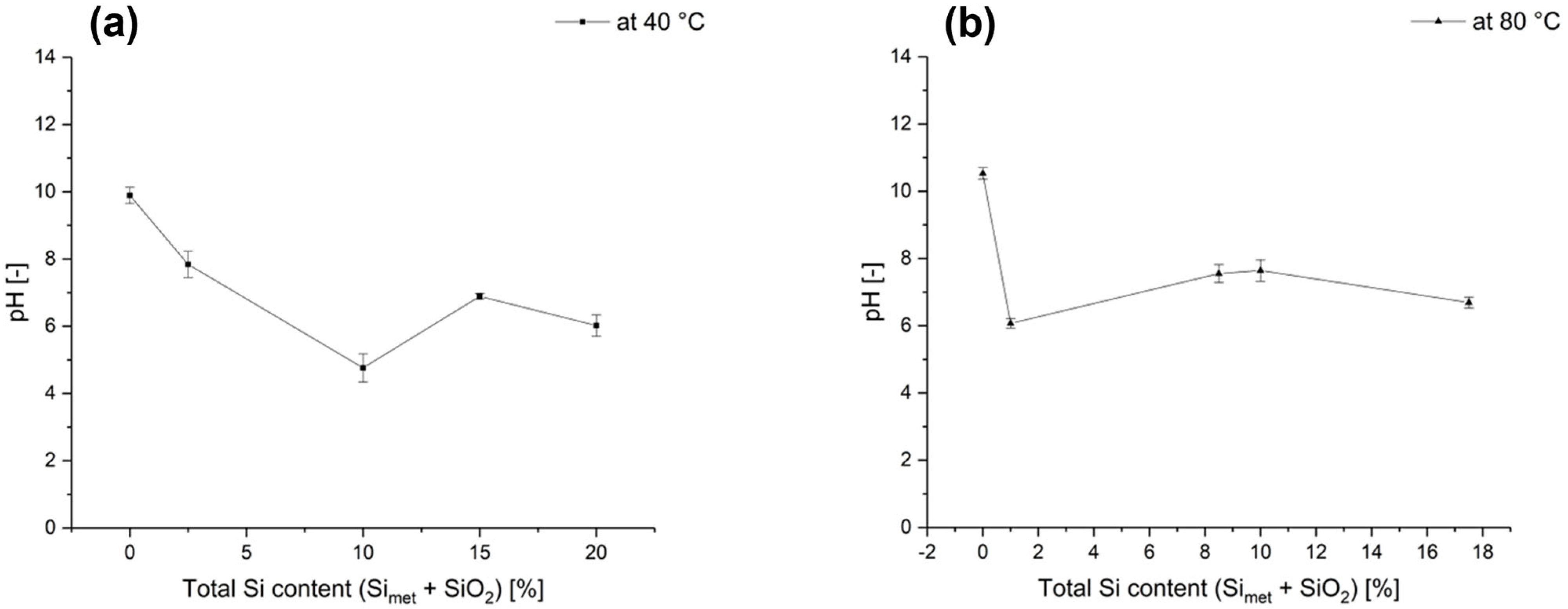
Due to the release of SO2 in the solution, a decrease in the pH value can be seen as a function of the Si (SiO2 and Simet) content. Figure 5 shows this behaviour as an example for an H2SO4 concentration of 0.1 mol/L at (a) 40 and (b) 80 °C. In both cases, the solutions show significantly higher pH values at the end of leaching during the absence of silicon than if the transition metal or the corresponding oxide is added. Similar behaviour could also be detected for higher concentrated leaching solutions (e.g., 5 M H2SO4).

3.2. Influence on the Viscosity

Based on these considerations, the viscosities of the solutions were examined more closely as a function of the sulphuric acid concentrations and the H2O2 content. Clear dependencies could be demonstrated by the created statistical model in this context. Figure 6 shows that an increased H2SO4 concentration especially leads to an increase in the viscosity (absolute values are more than doubled over the tested concentration range). The addition of H2O2 also leads to a further enhancement of the viscosity values, based on the reaction Equations (3) to (5). The simple application of 5-molar H2SO4 or the H2O2 content by itself do not lead to the viscosity changes shown, since the viscosities at maximum proportions of H2SO4 (5 mol/L) and H2O2 (5 vol.-%) amount to 15.2 and 17.2 mPas, respectively. The calculation of the mean values of the viscosities for tests with maximum leaching and reducing agents (5 mol/L H2SO4 and 5 vol.-% H2O2) resulted in an average viscosity of 29.0 mPas, while those for tests with minimum proportions of initial media (0.1 mol/L H2SO4 and 0 vol.-% H2O2) resulted in a value of 19.9 mPas.
Based on the analysis using the statistical planning and evaluation programme Modde 12.1, the dependencies of the essential parameters can be predicted. In order to provide an overview of the entire experimental space, contour plots at extreme values for temperature and S/L ratio are considered in the following section.
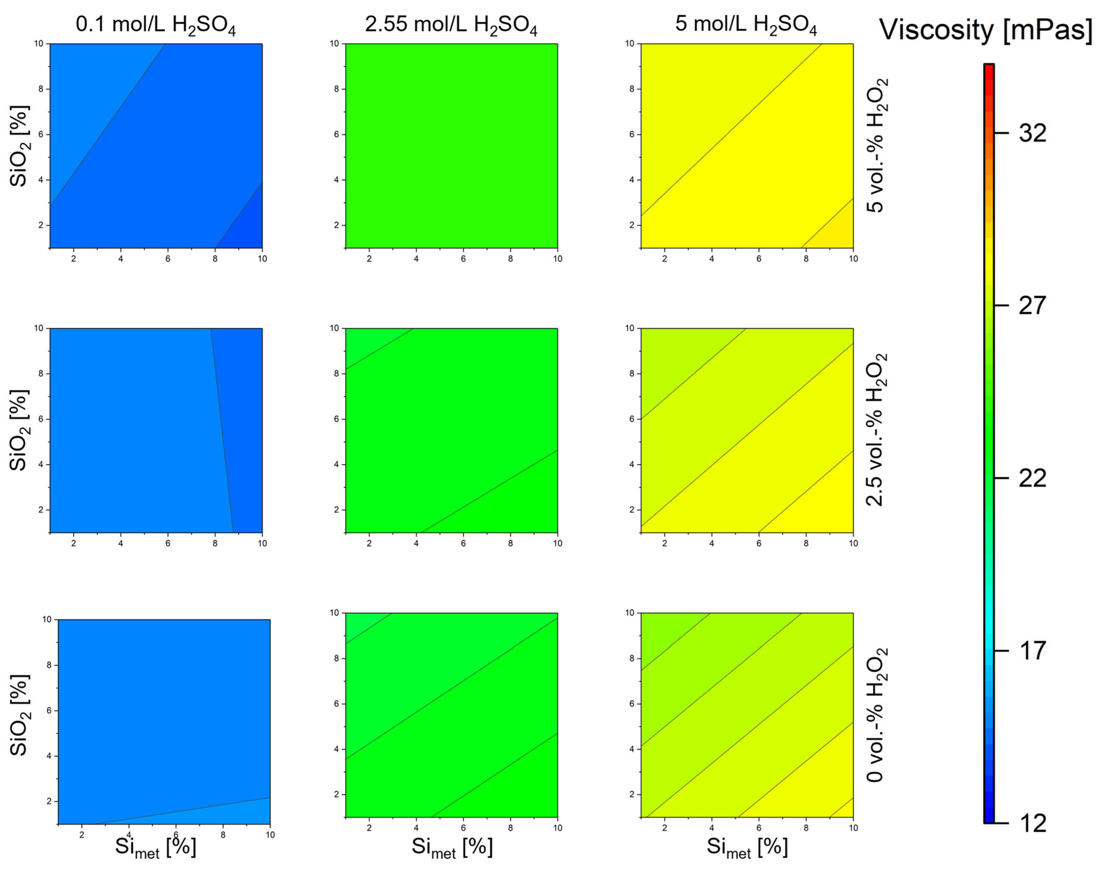
Figure 7 shows the contour plot at a leaching temperature of 40 °C and the lowest S/L ratio of 50 g/L. Because of the significantly lower mass concentration of valuable metals due to the low solid input, the lowest values for viscosity in absolute terms are also shown at high Si contents (silicon is considered as a cumulative parameter in this representation) in the solution. However, the trend shows that the highest viscosities in the pregnant leaching solutions are achieved over a broad design area at high H2SO4 concentrations with and without the H2O2 addition.
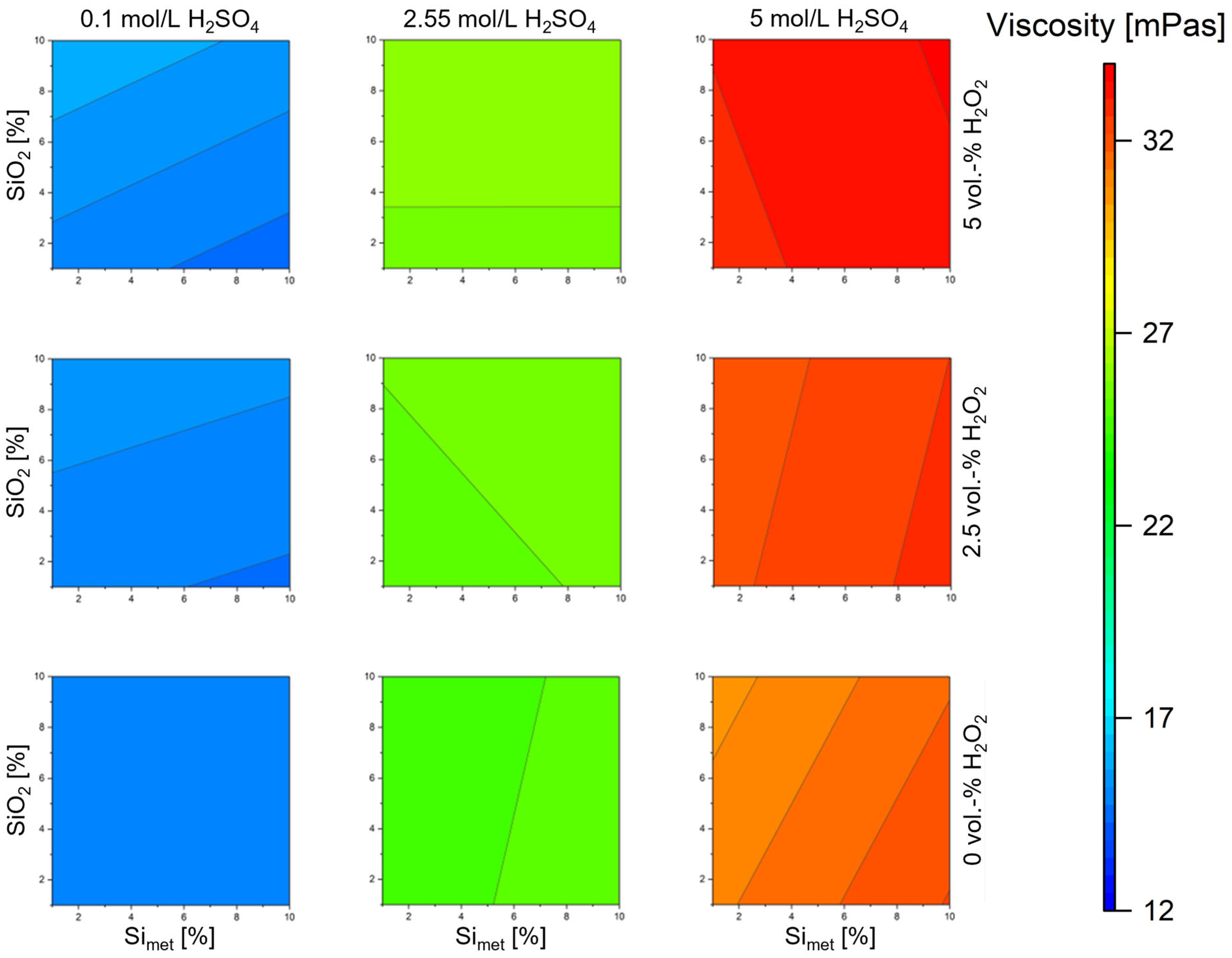
In comparison, in Figure 8, at a leaching temperature of 80 °C and a constant S/L ratio of 50 g/L, an increase in viscosity can already be observed at lower H2SO4 and H2O2 concentrations. Due to the faster kinetics at a higher temperature, the reaction sequence towards metasilicic acid can thus also be influenced. At maximum concentrations of leaching and reducing agents (5 mol/L H2SO4 and 5 vol.-% H2O2), an increase in the maximum appearing viscosity is also evident, compared to Figure 7.
At maximum temperature (80 °C) and a high S/L ratio (100 g/L), the maximum values for the viscosity of the pregnant leaching solution can be achieved (see Figure 9). At high acid and H2O2 concentrations as well as high silicon contents, a broad range is shown in which viscosities of more than 33 mPas appeared. Furthermore, it can be seen that even at lower H2O2 contents, a significant increase in viscosity can be observed.
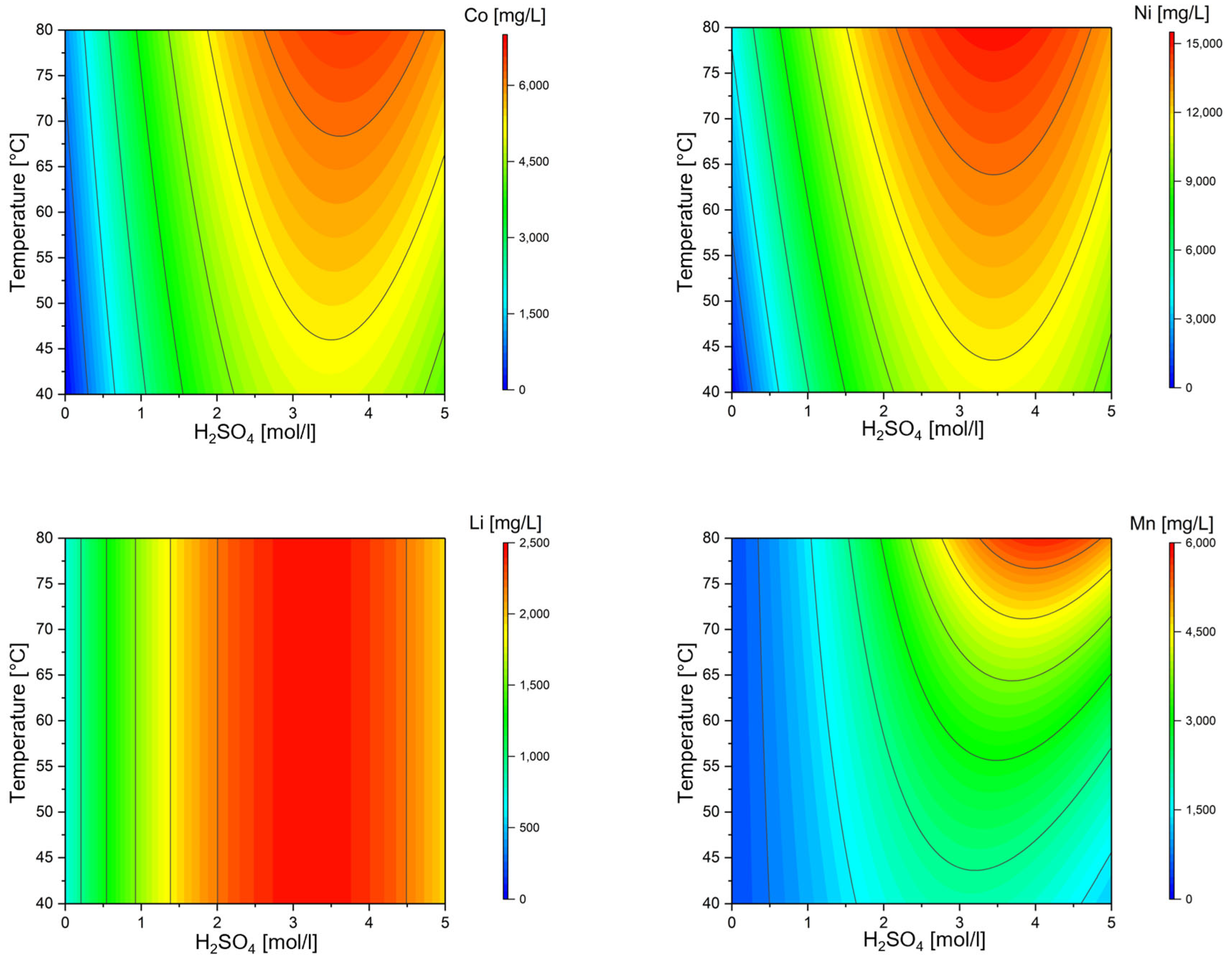
Based on these evaluations, the leaching efficiencies for the valuable metals cobalt, nickel, lithium and manganese are evaluated, taking into account the Simet and SiO2 contents in the pregnant leaching solutions. As can be seen in Figure 10, Co, Ni and Mn show similar behaviour in the context of leaching without the addition of H2O2 but with the maximum silicon addition (Simet + SiO2). Lithium, on the other hand, completely dissolves from a H2SO4 concentration of approx. 2.2 mol/L, regardless of the leaching temperature. This is also in line with experience from previous research and literature, as lithium can be rapidly and easily converted into solution. It is also shown that with a fixed leaching period of 240 min, the maximum achievable leaching rates are already attainable with the application of a 3-molar H2SO4 leaching system and temperatures of approx. 75 °C.
Figure 11 shows the counterpart of Figure 10 without the addition of Si or SiO2, while all other parameters were kept constant. It can be clearly seen that the leaching behaviour of the individual elements is similar. However, the absolute concentrations of the elements in the pregnant leaching solution are significantly higher than those in Figure 10. On the one hand, this proves that the leaching behaviour is worsened by the presence of Simet or SiO2 in the solution. On the other hand, this can be caused by the acid consumption according to reaction (5) and also by the resulting increased viscosity of the leaching solution in general. This is accompanied by a significant deterioration in the leaching efficiency of all considered valuable elements, as well as a restriction of the selectable parameter range. Another possibility, especially for the poorer leaching results for lithium, is the biding of undesirable lithium silicates (Li2SiO3). This counteracting process leads to an undesired deposition of lithium, which can no longer be brought into solution due to the presence of Si.
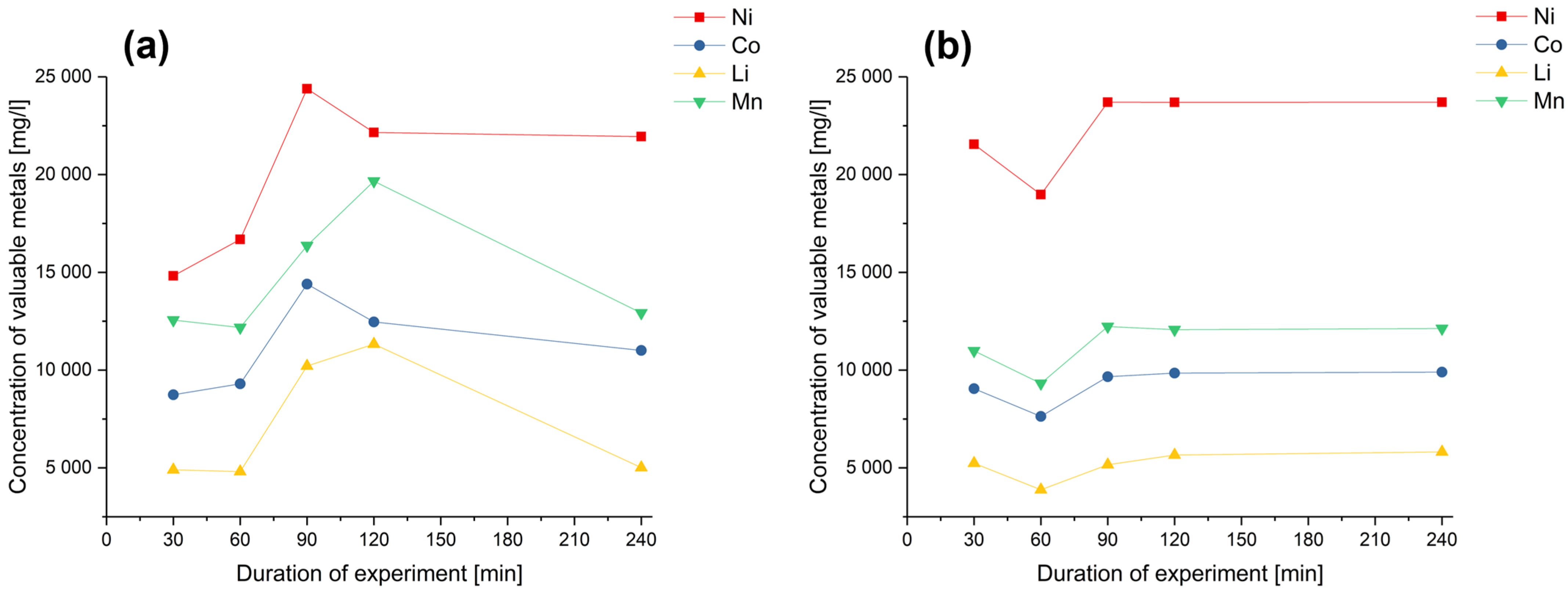
Another influencing factor for optimal leaching results is the process time. To study this parameter in detail, samples were taken for all experiments after a period of 30, 60, 90, 120 and 240 min and analysed for valuable metal contents. Figure 12 shows an example of the comparison of the concentration curves for results at (a) 0% silicon content (Simet + SiO2) and (b) 20% silicon content in the sum of Simet and SiO2. It can be seen that the valuable metals dissolve quickly in both cases. From this, the conclusion can be drawn that the leaching time after 90 min as a minimum only plays a subordinate role and thus does not represent the main influencing factor for the leaching efficiency in this system.
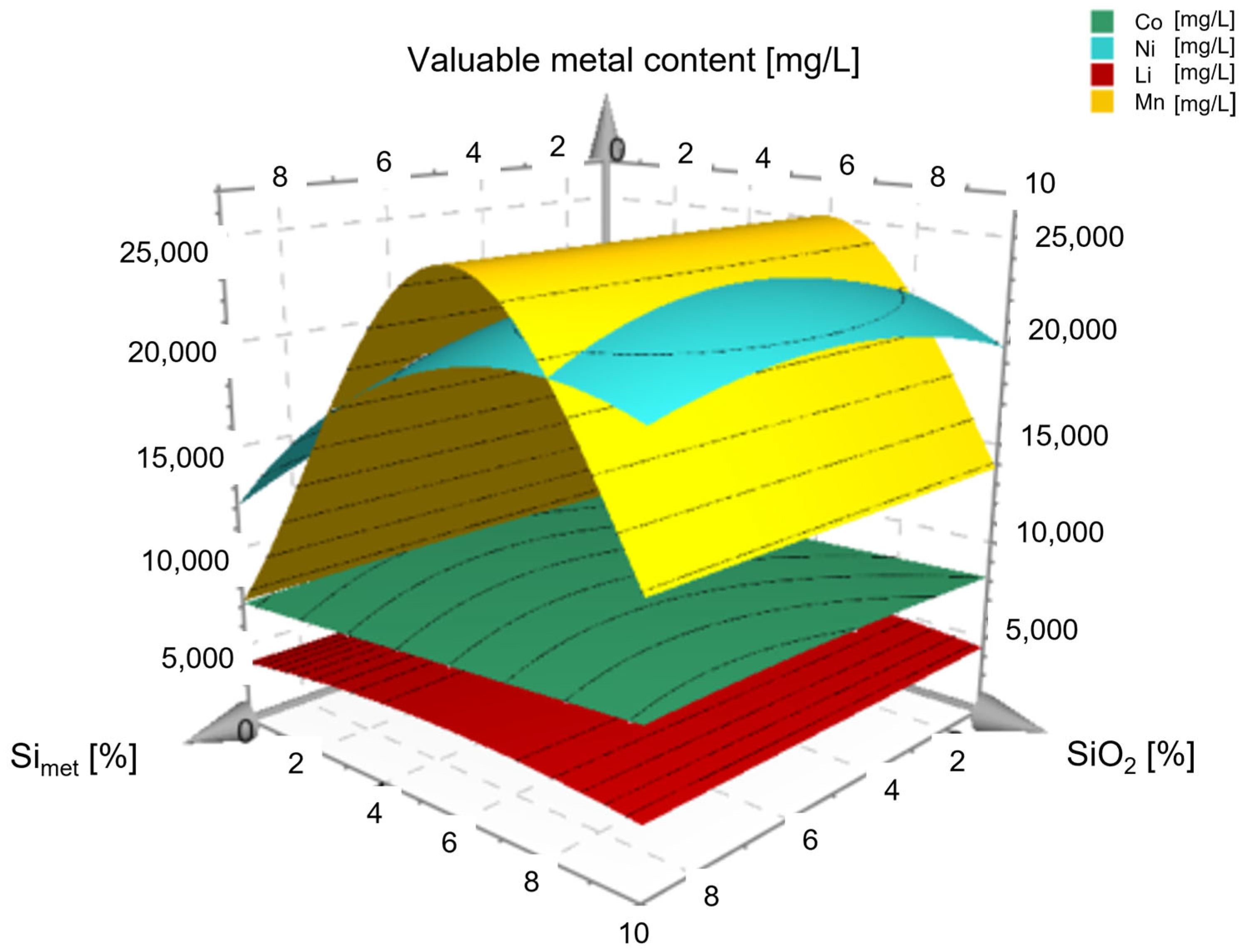
Based on the considerations presented and the results for the leaching efficiency of the valuable metals, the possibility of preparing a three-dimensional model arose (see Figure 13). This model shows the dependence of the leaching efficiencies on the presence of Simet or SiO2 and thus allows an assessment of the behaviour of this multi-component system. It shows a changed leaching behaviour as well as a kinetic inhibition, compared to leaching experiments that were not influenced by increased Si contents.

4. Conclusions

Silica has been a broadly discussed topic in hydrometallurgy for many years with regard to influencing the viscosity of solutions. Since silicon is currently used both for doping anode material with SiO2 and silicon itself can be used as anode material, this topic also plays a role in hydrometallurgical recycling processes for lithium-ion batteries. In order to keep the experimental effort in this publication within limits, on the one hand a well-known system (H2SO4 as leaching agent and H2O2 as reducing agent) was used, and on the other hand a statistical experimental design and evaluation programme (Modde 12.1) was approached. By using a quadratic model, a large number of parameters as well as their interactions or quadratic influences could be investigated. In general, the Si content (Simet + SiO2) has a significant influence on the viscosity of the resulting pregnant leaching solution as well as on the leaching behaviour of the valuable metals. It could be shown that two reaction paths lead to the formation of metasilicic acid through the application of H2O2 and H2SO4. This tends to form a jelly-like consistency and thus reduces the leaching efficiency. In addition, leaching rates are further degraded by the additional consumption of sulphuric acid for the formation of metasilicic acid. Furthermore, it could be postulated that the test time (30 to 240 min) only exerts a minor influence on the corresponding leaching rates after 90 min, in this context. Based on these results, it can be concluded that an early separation of the silicon content and also the avoidance of H2O2 lead to a significant improvement in the leaching efficiencies of the valuable metals as well as to an avoidance of viscosity increases. Although individual experimental data indicate that there is no direct evidence that H2O2 in combination with a silicon source inhibits leaching, evaluation of the statistical data shows this to be the case. It is essential to note here that in this field of research by no means all of the side reactions taking place have been understood, and further basic research is necessary. The present work should be a basis for further investigations. This is an essential aspect, especially with regard to industrially implemented processes, as viscosity changes can lead to significant reductions in turnover in the process as well as problematic blockages, etc. The investigations in the present study demonstrates clearly which reaction mechanisms favour viscosity increases and must therefore be avoided as far as possible.

Author Contributions

Conceptualization, E.G. and R.L.; methodology, E.G.; software, E.G.; validation, E.G.; formal analysis, E.G.; investigation, E.G., resources, H.A.; data curation, E.G.; writing—original draft preparation, E.G.; writing—review and editing, E.G. and H.A.; visualization, E.G.; supervision, E.G.; project administration, E.G.; funding acquisition, H.A. All authors have read and agreed to the published version of the manuscript.

Funding

This research received no external funding.

Informed Consent Statement

Not applicable.

Data Availability Statement

Not applicable.

Conflicts of Interest

The authors declare no conflict of interest.

References

  1. Queneau, P.B.; Berthold, C.E. Silica in Hydrometallurgy: An Overview. Can. Metall. Q. 1986, 25, 201–209. [Google Scholar] [CrossRef]
  2. Sjöberg, S. Silica in aqueous environments. J. Non-Cryst. Solids 1996, 196, 51–57. [Google Scholar] [CrossRef]
  3. Wiberg, N. Lehrbuch der Anorganischen Chemie; 102 Auflage; De Gruyter: Berlin, Germany, 2007. [Google Scholar]
  4. Okamoto, G.; Okura, T.; Goto, K. Properties of silica in water. Geochim. Cosmochim. Acta 1957, 12, 123–132. [Google Scholar] [CrossRef]
  5. Iler, R.K. The Chemistry of Silica. Solubility, Polymerization, Colloid and Surface Properties and Biochemistry; John Wiley & Sons: New York, NY, USA, 1978. [Google Scholar]
  6. Gierada, M.; de Proft, F.; Sulpizi, M.; Tielens, F. Understanding the Acidic Properties of the Amorphous Hydroxylated Silica Surface. J. Phys. Chem. C 2019, 123, 17343–17352. [Google Scholar] [CrossRef]
  7. Belton, D.J.; Deschaume, O.; Perry, C.C. An overview of the fundamentals of the chemistry of silica with relevance to biosilicification and technological advances. FEBS J. 2012, 279, 1710–1720. [Google Scholar] [CrossRef]
  8. Binnemans, K.; Jones, P.T. The Twelve Principles of Circular Hydrometallurgy. J. Sustain. Metall. 2022, 9, 1–25. [Google Scholar] [CrossRef]
  9. Lunevich, L. Aqueous Silica and Silica Polymerisation. In Desalination—Challenges and Opportunities; Mohammad, H.D.A.F., Vatanpour, V., Taheri, A.H., Eds.; IntechOpen: London, UK, 2020. [Google Scholar]
  10. Xu, C.; Dai, Q.; Gaines, L.; Hu, M.; Tukker, A.; Steubing, B. Future material demand for automotive lithium-based batteries. Commun. Mater. 2020, 1, 99. [Google Scholar] [CrossRef]
  11. Shenggong, H.; Shimin, H.; Shaofeng, W.; Isao, M.; Xiang, L.; Xianhua, H. Considering Critical Factors of Silicon/Graphite Anode Materials for Practical High-Energy Lithium-Ion Battery Applications. Energy Fuels 2021, 35, 944–964. [Google Scholar]
  12. Zhang, M.; Li, J.; Sun, C.; Wang, Z.; Li, Y.; Zhang, D. Durable flexible dual-layer and free-standing silicon/carbon composite anode for lithium-ion batteries. J. Alloys Compd. 2023, 932, 167687. [Google Scholar] [CrossRef]
  13. Zhao, P.-Y.; Gonzalez, A.R.; Li, B.; Choy, K.-L. Eco-friendly aerosol multicoated silicon anodes in lithium-ion batteries. Mater. Lett. 2022, 324, 132677. [Google Scholar] [CrossRef]
  14. Christoph, N.; Thomas, S.; Axel, T. Recycling von Lithium-Ionen-Batterien: Chancen und Heraus Forderungen für den Maschinen- und Anlagenbau; Fraunhofer-ISI: Karlsruhe, Germany, 2021. [Google Scholar]
  15. Windisch-Kern, S.; Gerold, E.; Nigl, T.; Jandric, A.; Altendorfer, M.; Rutrecht, B.; Scherhaufer, S.; Raupenstrauch, H.; Pomberger, R.; Antrekowitsch, H.; et al. Recycling chains for lithium-ion batteries: A critical examination of current challenges, opportunities and process dependencies. Waste Manag. 2022, 138, 125–139. [Google Scholar] [CrossRef]
  16. Mohanty, A.; Sahu, S.; Sukla, L.B.; Devi, N. Application of various processes to recycle lithium-ion batteries (LIBs): A brief review. Mater. Today Proc. 2021, 47, 1203–1212. [Google Scholar] [CrossRef]
  17. Jung, J.C.-Y.; Sui, P.-C.; Zhang, J. A review of recycling spent lithium-ion battery cathode materials using hydrometallurgical treatments. J. Energy Storage 2021, 35, 102217. [Google Scholar] [CrossRef]
  18. Harper, G.; Sommerville, R.; Kendrick, E.; Driscoll, L.; Slater, P.; Stolkin, R.; Walton, A.; Christensen, P.; Heidrich, O.; Lambert, S.; et al. Recycling lithium-ion batteries from electric vehicles. Nature 2019, 575, 75–86. [Google Scholar] [CrossRef]
  19. Mossali, E.; Picone, N.; Gentilini, L.; Rodrìguez, O.; Pérez, J.M.; Colledani, M. Lithium-ion batteries towards circular economy: A literature review of opportunities and issues of recycling treatments. J. Environ. Manag. 2020, 264, 110500. [Google Scholar] [CrossRef]
  20. Chandran, V.; Ghosh, A.; Patil, C.K.; Mohanavel, V.; Priya, A.K.; Rahim, R.; Madavan, R.; Muthuraman, U.; Karthick, A. Comprehensive review on recycling of spent lithium-ion batteries. Mater. Today Proc. 2021, 47, 167–180. [Google Scholar] [CrossRef]
  21. Asadi Dalini, E.; Karimi, G.; Zandevakili, S.; Goodarzi, M. A Review on Environmental, Economic and Hydrometallurgical Processes of Recycling Spent Lithium-ion Batteries. Miner. Process. Extr. Metall. Rev. 2021, 42, 451–472. [Google Scholar] [CrossRef]
  22. Jia, T.; Zhong, G.; Lv, Y.; Li, N.; Liu, Y.; Yu, X.; Zou, J.; Chen, Z.; Peng, L.; Kang, F.; et al. Prelithiation strategies for silicon-based anode in high energy density lithium-ion battery. Green Energy Environ. 2022, in press. [CrossRef]
  23. Larouche, F.; Tedjar, F.; Amouzegar, K.; Houlachi, G.; Bouchard, P.; Demopoulos, G.P.; Zaghib, K. Progress and Status of Hydrometallurgical and Direct Recycling of Li-Ion Batteries and Beyond. Materials 2020, 13, 801. [Google Scholar] [CrossRef]
  24. Liu, H.; Sun, Q.; Zhang, H.; Cheng, J.; Li, Y.; Zeng, Z.; Zhang, S.; Xu, X.; Ji, F.; Li, D.; et al. The application road of silicon-based anode in lithium-ion batteries: From liquid electrolyte to solid-state electrolyte. Energy Storage Mater. 2023, 55, 244–263. [Google Scholar] [CrossRef]
  25. Naveenkumar, P.; Maniyazagan, M.; Yang, H.-W.; Kang, W.S.; Kim, S.-J. Nitrogen-doped graphene/silicon-oxycarbide nanosphere as composite anode for high-performance lithium-ion batteries. J. Energy Storage 2023, 59, 106572. [Google Scholar] [CrossRef]
  26. Li, P.; Zhao, G.; Zheng, X.; Xu, X.; Yao, C.; Sun, W.; Dou, S.X. Recent progress on silicon-based anode materials for practical lithium-ion battery applications. Energy Storage Mater. 2018, 15, 422–446. [Google Scholar] [CrossRef]
  27. Zhang, C.; Wang, F.; Han, J.; Bai, S.; Tan, J.; Liu, J.; Li, F. Challenges and Recent Progress on Silicon-Based Anode Materials for Next-Generation Lithium-Ion Batteries. Small Struct. 2021, 2, 2100009. [Google Scholar] [CrossRef]
  28. Luo, W.; Chen, X.; Xia, Y.; Chen, M.; Wang, L.; Wang, Q.; Li, W.; Yang, J. Surface and Interface Engineering of Silicon-Based Anode Materials for Lithium-Ion Batteries. Adv. Energy Mater. 2017, 7, 1701083. [Google Scholar] [CrossRef]
  29. Gerold, E.; Antrekowitsch, H. Potenzialabschätzung von Synergieeffekten zur simultanen Rückgewinnung von Wertmetallen aus komplexen, metallhaltigen Reststoffen. Osterr. Wasser Abfallwirtsch. 2022, 74, 22–31. [Google Scholar] [CrossRef]
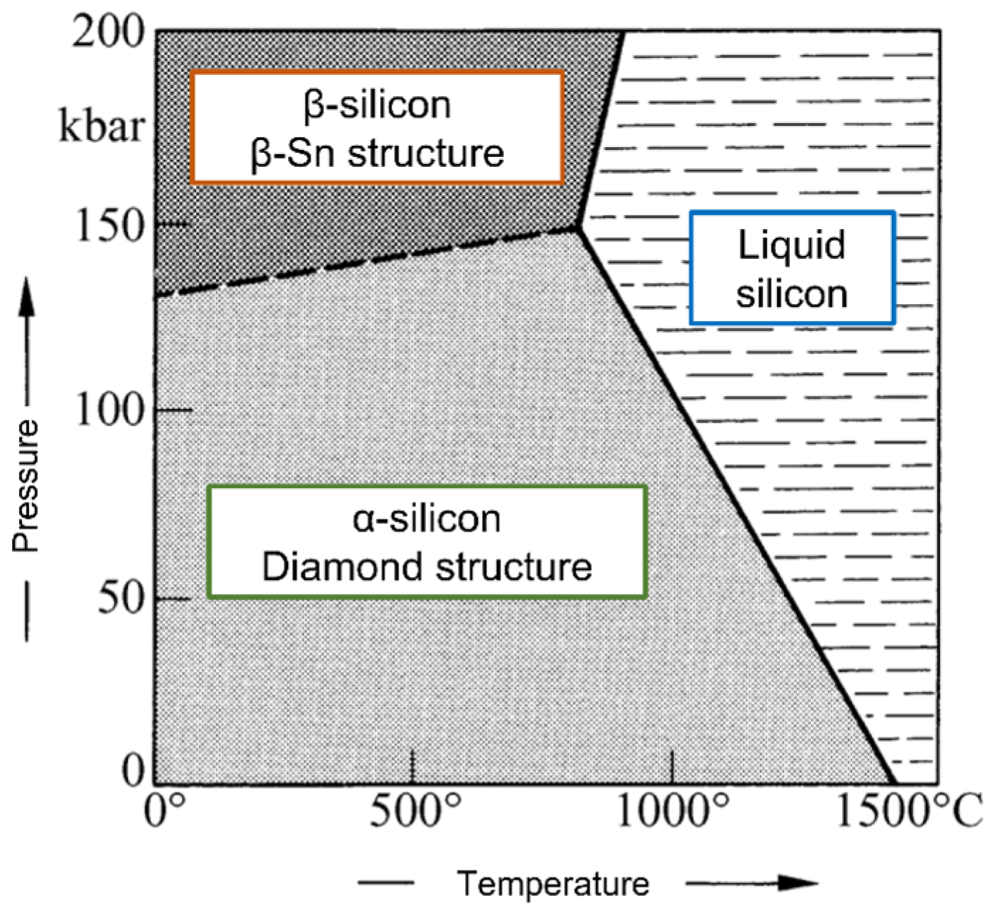
Figure 1. States of silicon with dependence on pressure and temperature, adapted with permission from Ref. [1].
Metals 13 00785 g001
Figure 2. Dependence of SiO2 solubility on temperature for amorphous silica, reprinted with permission from Ref. [1].
Metals 13 00785 g002
Figure 3. Dependence of gel time on pH in the absence of salts for Si sol stability, reprinted with permission from Ref. [1].
Metals 13 00785 g003
Figure 4. Results of the viscosity [mPas] determination of solutions 1 to 39 as a function of H2SO4 [mol/L] and H2O2 [vol.-%] concentration as well as the amount of SiO2 and Simet [mass-% of black mass] added to the solution.
Metals 13 00785 g004
Figure 5. pH of the solutions after the end of leaching (0.5 M H2SO4) at (a) 40 °C and (b) 80 °C as a function of the total amount of silicon (SiO2 + Simet) added.
Metals 13 00785 g005
Figure 6. Viscosity dependency on the concentration of (a) the leaching medium (H2SO4) and (b) the reducing agent (H2O2) with parameters at otherwise average values (60 °C, 75 g/L solids, 240 min), confidence interval of 95%.
Metals 13 00785 g006
Figure 7. 4D contour plot for the change in viscosity as a function of Simet, SiO2, H2SO4 and H2O2 concentration in the leaching solution at an S/L ratio of 50 g/L and a leaching temperature of 40 °C.
Metals 13 00785 g007
Figure 8. 4D contour plot for the change in viscosity as a function of Simet, SiO2, H2SO4 and H2O2 concentration in the leaching solution at an S/L ratio of 50 g/L and a leaching temperature of 80 °C.
Metals 13 00785 g008
Figure 9. 4D contour plot for the change in viscosity as a function of Simet, SiO2, H2SO4 and H2O2 concentration in the leaching solution at an S/L ratio of 100 g/L and a leaching temperature of 80 °C.
Metals 13 00785 g009
Figure 10. Contour plot of the statistical test evaluation for the leached fractions of Co, Ni, Li and Mn with addition of the maximum amount of Simet and SiO2 without the application of H2O2 and an S/L ratio of 50 g/L as a function of temperature and H2SO4 concentration.
Metals 13 00785 g010
Figure 11. Contour plot of the statistical test evaluation for the leached fractions of Co, Ni, Li and Mn without the addition of Simet, SiO2 or H2O2 as a function of temperature and H2SO4 concentration.
Metals 13 00785 g011
Figure 12. Concentration curve of Ni, Co, Li and Mn in the leaching solutions as a function of the leaching time in comparison with the results at (a) 0% and (b) 20% Simet and SiO2 (in total) with otherwise constant parameters (5 mol/L H2SO4, 80 °C, 100 g/L solids, 0% H2O2).
Metals 13 00785 g012
Figure 13. Surface plots for Ni, Co, Li and Mn leaching and their dependencies on the SiO2 and Simet content of the leaching solution.
Metals 13 00785 g013
Table 1. D-optimal design matrix for the conducted experiments with addition of Si metal and/or SiO2.
Exp. NameRun OrderConc. H2SO4TemperatureS/LConc. H2O2SiSiO2
[i][-][mol/L][°C][g/L][vol.%][wt.%][wt.%]
Si-112580100000
Si-2240.14083.3000
Si-3150.166.7100500
Si-4954066.7500
Si-5193.48050500
Si-65540501.72.50
Si-7293.44010052.50
Si-8220.153.350050
Si-921580500100
Si-10335401000100
Si-1130.1801000100
Si-1240.140505100
Si-13315801005100
Si-1412.660752.5100
Si-15260.180501.701
Si-16320.18083.357.51
Si-1760.1401003.302.5
Si-1814566.75052.52.5
Si-19283.4405007.52.5
Si-20131.74050007.5
Si-21250.18066.752.57.5
Si-22300.1401001.77.57.5
Si-23110.180500107.5
Si-243554083.35107.5
Si-2536580500010
Si-2675401000010
Si-27230.1801000010
Si-28270.140505010
Si-29385801005010
Si-30161.7401005510
Si-31370.180503.37.510
Si-321858010001010
Si-3385805051010
Si-34340.14066.701010
Si-35100.166.710051010
Si-362540503.31010
Si-37172.660752.555
Si-38392.660752.555
Si-39202.660752.555
Table 2. Composition of black mass measured via ICP-MS.
Black MassLiAlMnFeCoNiCu
[g/100 g]3.405.067.300.545.8022.206.90
Disclaimer/Publisher’s Note: The statements, opinions and data contained in all publications are solely those of the individual author(s) and contributor(s) and not of MDPI and/or the editor(s). MDPI and/or the editor(s) disclaim responsibility for any injury to people or property resulting from any ideas, methods, instructions or products referred to in the content.