Review

A Review on Direct Laser Deposition of Inconel 625 and Inconel 625-Based Composites—Challenges and Prospects

1
Faculdade de Engenharia, Universidade do Porto, s/n, R. Dr. Roberto Frias, 4200-465 Porto, Portugal
2
LAETA/INEGI, Instituto de Ciência e Inovação em Engenharia Mecânica e Engenharia Industrial, Campus da FEUP, R. Dr. Roberto Frias 400, 4200-465 Porto, Portugal
*
Author to whom correspondence should be addressed.
Metals 2023, 13(4), 787; https://doi.org/10.3390/met13040787
Submission received: 7 March 2023 / Revised: 9 April 2023 / Accepted: 11 April 2023 / Published: 17 April 2023
(This article belongs to the Special Issue Advanced Techniques for Metallurgical Characterization)

Abstract

:
The direct laser deposition (DLD) process has seen rigorous research in the past two decades due to its ability to directly manufacture products followed by minimal machining. The process input variables play a vital role in determining the properties achieved in the products manufactured by the DLD method. Inconel 625, a nickel-based superalloy with exceptional mechanical performance and corrosion resistance, has been used in critical applications within the aerospace, process, and marine industry. However, its poor machinability and higher load requirements for plastic deformation have been challenging for manufacturers. Therefore, many studies have explored the additive manufacturing of Inconel 625 to overcome these problems. This article focuses on the DLD of Inconel 625 and its composites, presenting the state-of-the-art, drawing a relation among laser processing parameters and resulting material properties, microstructure and phase evolution, and the high-temperature performance of DLD Inconel 625. The paper highlights the areas on which further studies may focus.

1. Introduction

Nickel-based superalloys are the preferred choice for applications involving fatigue and/or creep resistance and the ability to withstand corrosive attacks from the operating environment. These alloys have gained increasing popularity in the marine, aerospace, energy, and automobile sectors in the past few decades due to their unique properties. However, nickel superalloys have poor machinability causing excessive tool wear, shorter tool life, large power consumption, and low productivity during machining [1,2,3]. Additionally, these alloys have the propensity to accumulate residual stresses and various defects, which can promote catastrophic component failure during their service life [4]. This review focuses on the UNS N06625 alloy, also known as Inconel 625® (hereafter named IN625), a trademark of Specialty Metals Corporation®. Initially developed in the 1960s, IN625 has been widely used for diverse engineering applications after some modifications. Due to the considerable difficulty and lengthy process times required for machining IN625, additive manufacturing (AM) techniques have been explored as an alternative to conventional fabrication methods for bulk and cladding surface protection.
AM of metals, with its exceptional freedom of creating complex geometries using layer by layer fabrication approach combined with tailored material properties, has unveiled a new horizon of manufacturing. With more recent developments each year, AM has evolved from a rapid prototyping technology into a preferred fabrication method in several industries for a substantial number of products. Regarding the non-sintering methodologies presented in ISO-ASTM 52900, AM processes involve power sources such as electron or laser beams, arc, and plasma [5] (pp. 3–10). Based on the type of raw materials consumed, these AM processes can be classified into powder bed, direct powder feed (via coaxial nozzle), or wire feeding process. AM of nickel superalloys has gained particular interest from researchers in the past few years, as evident by Figure 1, showing the year-on-year increase in the number of relevant research articles in the last five years. However, parts produced by these methods generally need hot isostatic pressing or at least a suitable heat treatment as a post-processing treatment.
Laser-directed energy or direct laser deposition (DLD) can be used for single or multi-material deposition for repair, cladding, or producing large-volume parts. DLD is defined as a “process in which focused thermal energy of the laser melts the material being deposited”. DLD processes can use multi-kW lasers with spot sizes of several millimeters to deposit as much material per unit of time as possible. Being an in-situ powder feeding process, it allows fabricating parts without any enclosed chamber. DLD can also produce components with different compositions, layer by layer, through the mixing of different powders, known as functionally graded materials, which is challenging to realize in laser powder bed fusion (LPBF). As an example, DLD systems, such as those offered by RPM Innovations®, can deposit over a meter-long complex shape. Scaling to even larger sizes is possible, as robots can be attached to large gantry systems and moved over large distances [6]. DLD also offers the possibility of freedom from cost-intensive post-processing operations, e.g., hot isostatic processing (HIP), heat treatment, surface finishing, etc., which are usually complementary to AM components built by LPBF techniques. However, such additional post-processing steps tend to undermine the business case for using AM production [6].
Considerable research activity has been aimed at DLD manufacturing of nickel superalloys, which has inspired several reviews focusing on processing parameters, microstructural features, and mechanical properties [7,8,9,10,11,12]. However, considering the growing interest and rapid advancement in the development of DLD IN625 and IN625-based advanced composites, the literature asks for a quick update to cover emerging concepts and issues related to metallurgical features in AM material.
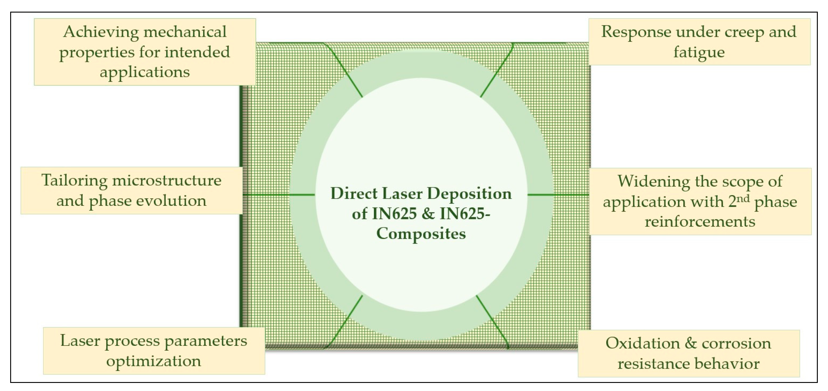
This review paper shall present the state-of-the-art in AM of IN625 and its composites using DLD, highlighting the effect of laser processing parameters, the effect of the reinforcements’ composition, size, and shape, significant technical challenges, and particular areas that may be the focus of future studies for accelerated development in this specific domain. Figure 2 presents a brief overview of key areas covered in this article.

2. Wrought vs. Additive Manufactured IN625

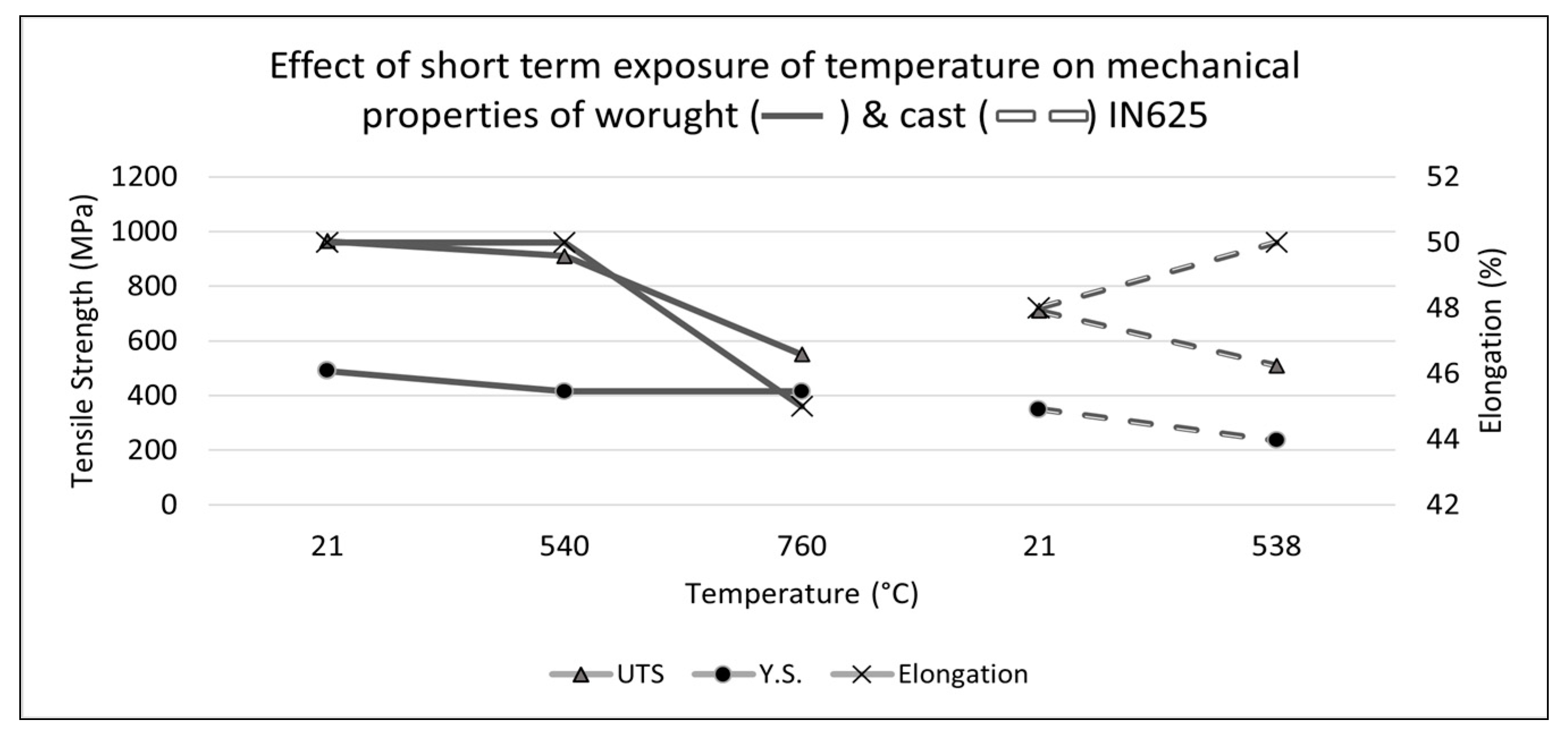
IN625 was initially developed as a solid solution-strengthened alloy for high-temperature applications, although the alloy can also gain some further strength by carbide and/or intermetallic compound precipitation [13]. It has good weldability and fabricability, making it suitable for diverse engineering applications, particularly involving high-temperature creep and/or fatigue conditions. The mechanical properties of wrought IN625 upon short-term elevated temperature exposure are shown in Figure 3.
An unusual drop has been observed in the elongation (%) of wrought IN625 heated at 760 °C, although the authors did not present any justification for this reduction [2]. However, this sharp decline observed in the elongation of wrought IN625 can be attributed to the strain rate applied in the tensile test. Some authors mentioned this behavior for a similar alloy tested at 600 °C [14]. Some other authors [15,16] have also evidenced such behavior in tensile properties during the tensile test at a similar temperature.
High melting solute elements (molybdenum, niobium) have a low diffusivity in nickel matrix [17]; thus, their presence in solid solution enhances the creep strength of the alloy [18], while chromium, although having a small hardening coefficient, still contributes appreciably to solid solution-strengthening due to its high weight fraction in IN625 [19]. Carbon also serves as a potent solid solution strengthening element as well as a source for primary and secondary carbide strengthening [20]. IN625 has a face-centered cubic (FCC) crystal structure similar to other nickel-based superalloys, which resist phase transformations from room temperature up to the melting point. In addition, the FCC structure has lower rates of thermally activated processes influencing the creep deformation phenomena. The resistance to external surface degradation by oxidation and hot corrosion is controlled primarily by chromium, aluminum, and titanium [19]. Since most IN625 components are complex in shape, excessive machining combined with the hard-to-machine nature of alloy poses considerable difficulties during manufacturing. In addition, the formation of IN625 needs much higher power during forming processes (~4 times that of carbon steels) [21].

Mechanical Properties

Wrought IN625 has moderately high mechanical properties at room temperature. However, its elevated temperature mechanical properties distinguish it from steels having equivalent strengths. ASTM B443 specifies the minimum requirements for sheet/plate, and the ASTM B564 standard specifies the requirements for IN625 forging. ASTM E8 and ISO 6892 are the standard methods for room temperature uniaxial tension testing of metallic materials, while ASTM E21 and ISO 6892 provide methods for tension testing of metals at elevated temperatures (above 38 °C), applicable to both wrought and AM IN625. ASTM E292 and ASTM E740 standard test methods determine the rupture strength (elevated temperature) and residual strength in the notched specimen under tensile loading. The test methods mentioned above apply to both conventionally and additively manufactured IN625 material. However, they may be used with caution when considering the requirements of powder metallurgy materials to cover AM products whenever applicable. Furthermore, in the case of some tests (e.g., test against ASTM E740), certain limitations, such as specimen thickness or specimen geometry, may be encountered in AM material testing [22].
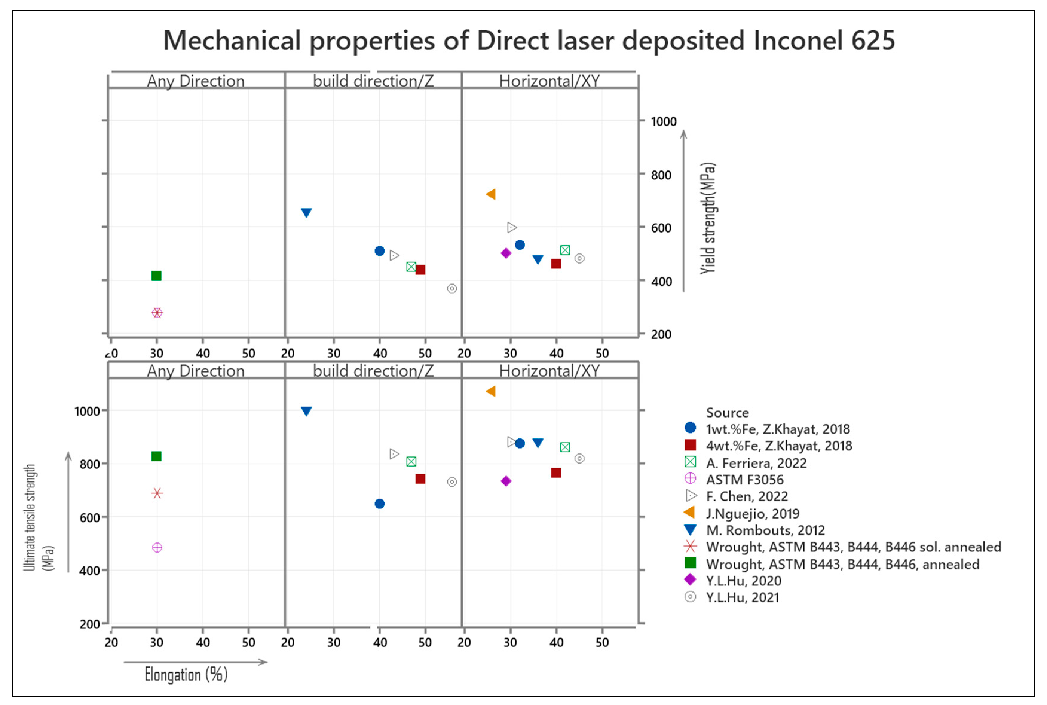
Several efforts have been made for AM of IN625 using DLD in the past few years. Figure 4 presents an overview of the mechanical properties reported by various studies, and the mechanical property specifications of conventionally manufactured IN625 are also given for reference. All properties shown here are without subsequent post-processing heat treatment.
DLD IN625 meets/surpasses the ultimate tensile strength (UTS), yield strength (YS), and elongation (%) specification for conventionally manufactured IN625 products. However, the AM IN625 generally presents lower ductility when compared with conventionally manufactured IN625, having typical elongation values lying between ~60 and 65%. DLD builds have higher UTS, YS, lower %elongation in the XY direction, and lower UTS, YS, and higher elongation in the Z-direction. Isotropic behavior is evident in the mechanical properties of DLD builds. Most DLD builds present a UTS and YS within 820–880 MPa and 460–600 MPa, respectively, in the XY (horizontal)-direction and 730–840 MPa and 370–510 MPa in Z (build)-direction, respectively. In recent works, the reported elongation values lie between 29 and 45% in the XY direction and 40 and 56% in the Z-(build) direction. The orientation dependence of properties is mainly attributed to the characteristic columnar structure resulting from the DLD process, which results in a variation in mechanical properties with reference to the tensile loading direction during tension tests [31]. Laves phase is formed during the terminal stage of solidification and distributed in between the dendrites [32]. The microstructure evolution of Laves phase is discussed in Section 3.1.
Two different studies have been conducted to compare the mechanical properties of builds produced by selective laser melting (SLM) and DLD [23,24]. J. Nguejio et al. [24] concluded that with adequate parameters and post-heat treatment, DLD provided better strength with more than 40% elongation compared to SLM build. Whereas F. Chen et al. [23] reported relatively lower (~30%) elongation and a lower strength with considerable variation in elongation in XY and Z directions for DLD builds as compared to SLM builds after heat treatment with minimal anisotropic behavior. Thus, the selection of the process has its own merits for a certain product and desired mechanical properties for the intended application. However, for demanding applications, it can be diminished by suitable post-heat treatment of AM products [31].

3. Microstructure and Phase Evolution in Direct Laser Deposited IN625

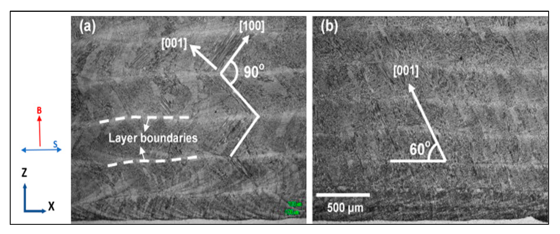
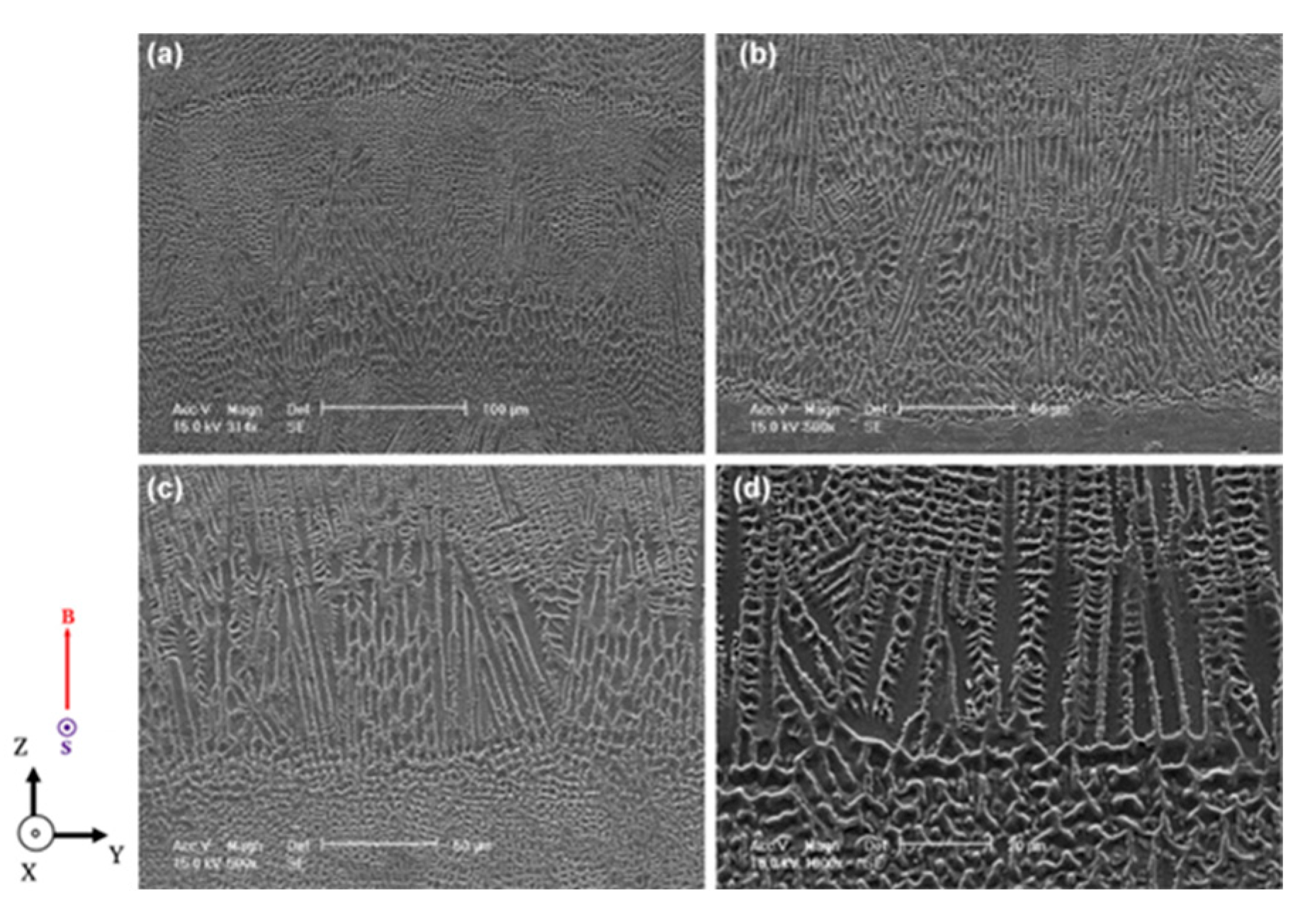
Several researchers have studied the microstructure evolution and phase transformation in DLD IN625. However, a lack of sufficient information about the location/orientation of the sample or adopting non-standard practices in others may render the data less beneficial to the reader. An effort has been made here to present micrographs with sample orientation information symbols on each (wherever sufficient information is available from the original work). ASTM 52921 [33] terminology guidelines have been adopted for presenting the orientation of samples. IN625 has been successfully deposited using DLD by several researchers without relevant defects, such as cracks, high porosity, or bonding errors, at the interface between the substrate and deposit. Figure 5 shows the longitudinal (X-Z) section of a multi-layer deposition of IN625 using DLD by G.P. Dinda et al. [34]. The microstructure consists of columnar dendrites growing epitaxially from the substrate, wherein the growth direction of the primary dendrites is tied to the laser scanning direction. Figure 5a shows an angle of 90° among two adjacent layers, and Figure 5b shows a uniform inclination angle of 60° to the horizontal plane resulting from a unidirectional scan. Cooling occurs not only via the substrate and previously deposited layers, but the adjacent deposited layers also play a partial role. It is clear from Figure 5 that the dendritic growth occurs in the opposite direction to the resultant heat flux.
Since the cooling direction changes with the scan direction, the resultant heat flux direction rotates to be very close to the direction of secondary dendrites of the preceding layer. These secondary dendrites act as a growth site for the primary dendrites of newly solidifying layers, which results in an angle of 90° among the primary dendrites in subsequent layers.
Figure 6 presents the X-Z section of DLD IN625 [34], which shows that each DLD layer comprised two distinct microstructures—a bottom columnar dendritic structure with no dendrites and an upper dendritic structure with secondary dendrites—due to comparatively slower cooling in the upper portion of the layer.
The X-Y section (horizontal section) of a similar sample (Figure 7) shows cellular microstructure as typically expected from a sectional view of a columnar dendritic structure.
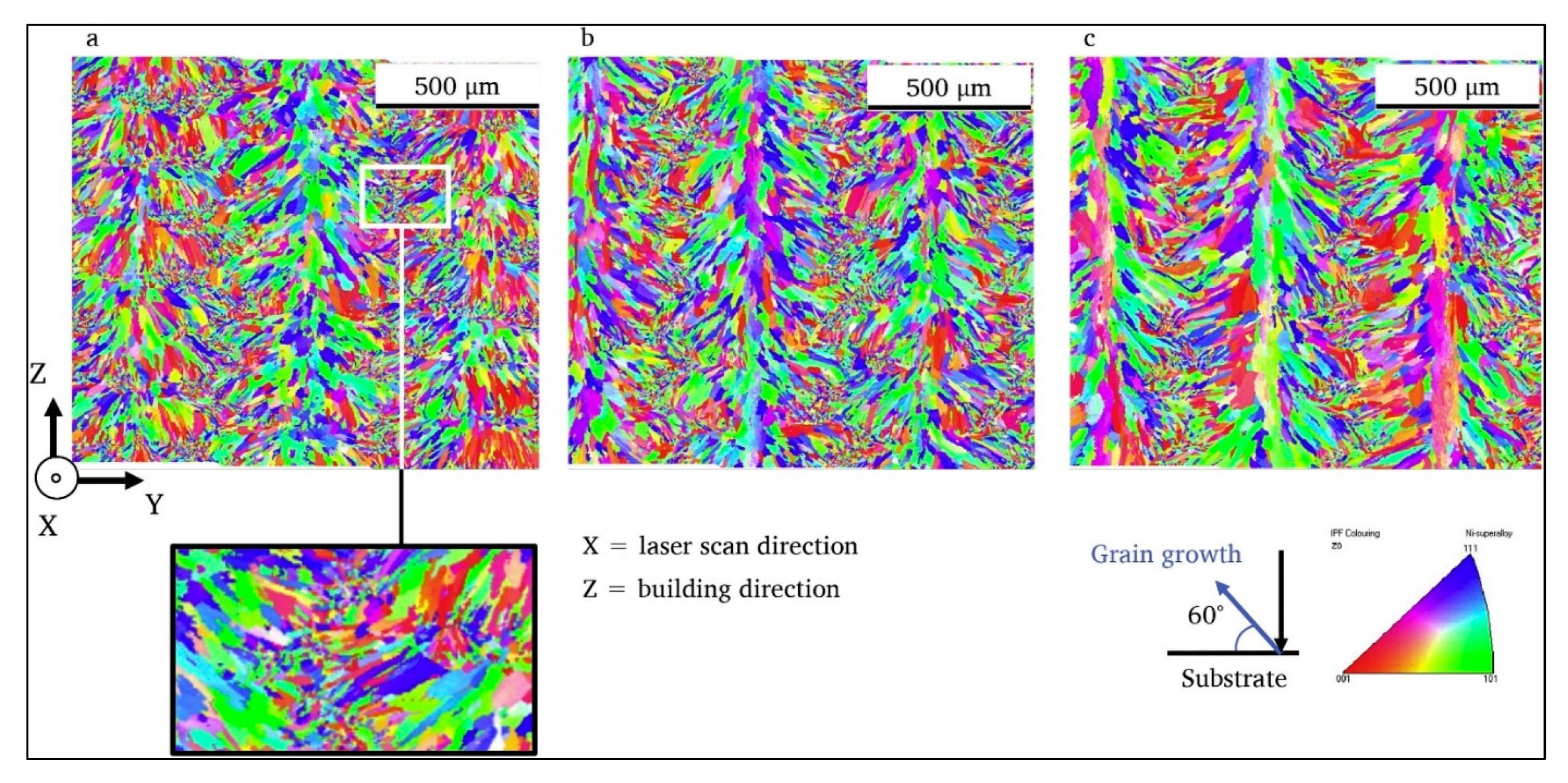
Although it has been indicated in the literature [34,35] that the grains preferentially orient to <001> due to the vertical heat flux direction, resulting in the growth of primary dendrites at an angle of about 90° with the substrate, J. Nguejio et al. [24] reported that primary dendrites are not oriented at a right angle to the substrate, and instead appear as inverted V’s in deposited layers, as shown in Figure 8, electron backscatter diffraction (EBSD) analysis. A similar inverted V-pattern is also visible in the results of A.A. Ferreira et al. [25], who used DLD for the deposition of IN625 on a high-strength low alloy (HSLA) steel. In addition, it can also be observed in Figure 8 that the application of a comparatively lower power input resulted in the evolution of finer morphology and a higher ratio of smaller grains in the intersecting region between adjacent deposit lines.
Sanjay K. Rai et al. conducted a microstructural characterization study using X-ray diffraction (XRD). They demonstrated that although the XRD peaks from coherent precipitates cannot be seen separately, their presence could be easily detected by analysis of the XRD patterns of the matrix. The three parameters, namely lattice parameter, micro-strain, and crystallite size, can be used to indicate the occurrence of precipitates in the matrix, the coherency of precipitates, and the detection of early precipitation of the incoherent phase, respectively [36].
Researchers have related the formation and dissolution of precipitates in a matrix with the lattice parameter for DLD-IN625, which has been summarized in Table 1, with relevant reference sources. Lattice constants calculated from (200) diffraction peaks in wrought samples [24] are also given for reference.
The laser source power results in a variety of microstructures, although typically DLD process results in a columnar dendritic structure. However, stress relieving at 1066 °C for 1.5 h, followed by hot isostatic pressing at 1163 °C for 3 to 4 h in inert gas at 100 MPa pressure, followed by solution annealing treatment at 1177 °C for 1 h of DLD-IN625 can promote recrystallization and grain growth, producing a near equiaxed grain structure [37]. An increase in laser power results in a decrease in the ultimate tensile and tensile yield strengths, as shown in Figure 9. An increase in the grain size driven by an increase in laser power input causes a decrease in the microhardness of the resulting DLD-IN625 build, with a lower relative density, at 2620 W power input, as shown in Figure 9.

3.1. Laves Phase and Carbides

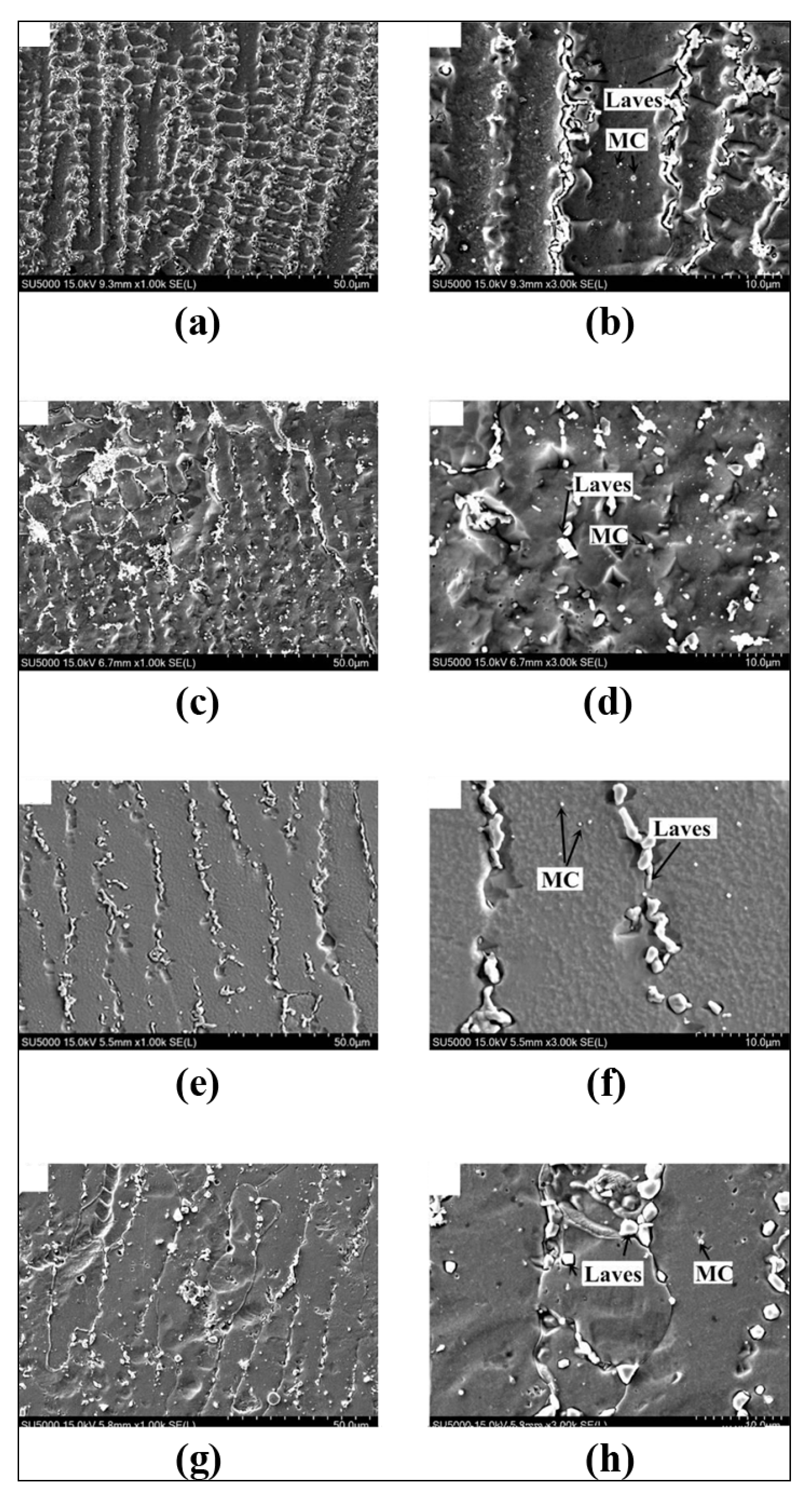
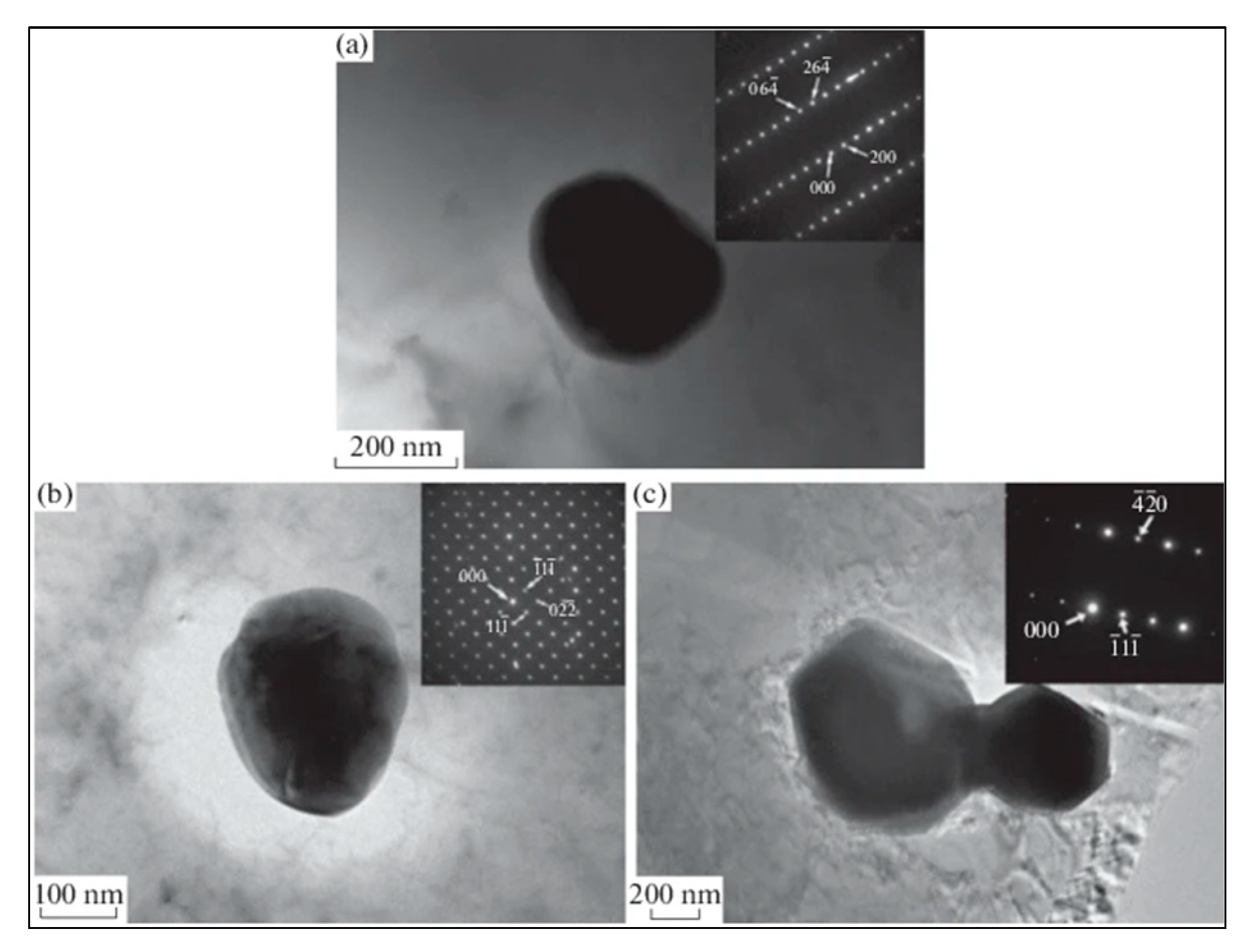
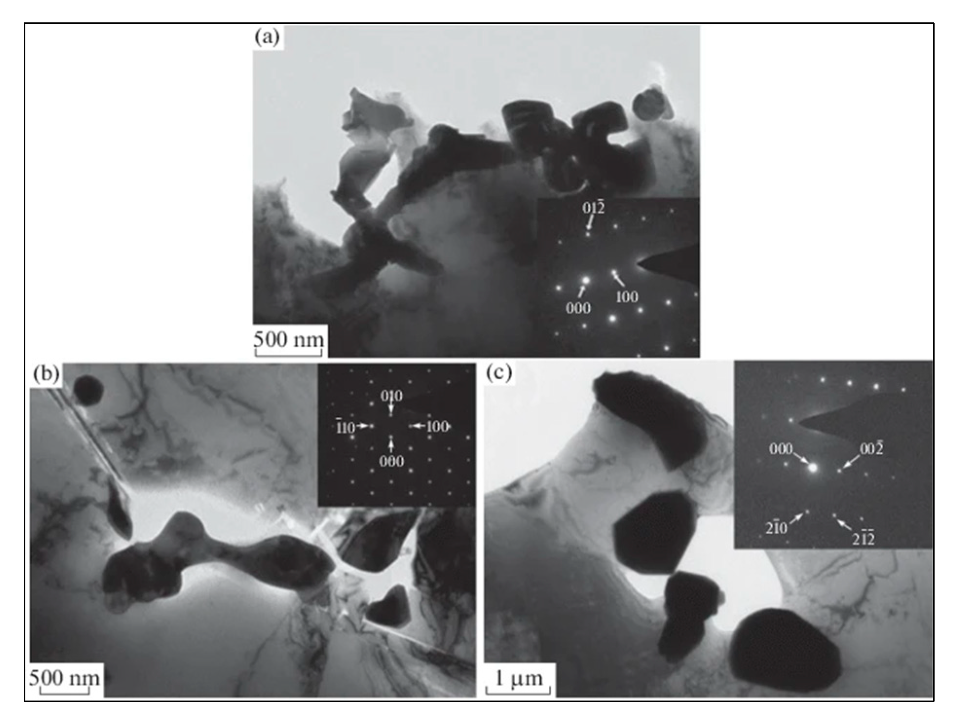
Figure 10a,b present the vertical cross-section (parallel to the building direction) of the DLD-IN625 in the as-built condition. Very fine precipitates with a brighter contrast can be observed as a continuous chain-like distribution and small block-like precipitates within the inter-dendritic region. These precipitates are identified as Laves phases and MC carbides [38] using localized chemical analysis. However, the formation of these phases can be confirmed by applying transmission electron microscope (TEM) analysis, as shown in Figure 11 and Figure 12 [39]. According to the Ni–Nb–C equilibrium phase diagram, with sufficiently high concentrations of Nb and C in the molten pool, MC carbides are precipitated by eutectic reactions (L --> γ + MC), which are characterized by spherical/blocky morphology and cubic crystal structure, as observed by TEM and the corresponding selected area electron diffraction (SAED) pattern in these images. When the as-built DLD-IN625 is heat treated at 1000 and 1100 °C (Figure 10c,d, respectively), the recrystallization tends to proceed with increasing temperature and some of the Laves phase particles dissolve into the solution to precipitate as MC carbides. The rest of the Laves phase particles tend to transform into rod-like shapes [39]. A similar phenomenon has been observed and confirmed using TEM and SAED analysis where the Laves phase transforms from irregular shapes to a short bar-like/particle shape when annealed at 1200 °C for 1 h [39]. The evolution of Laves phase morphology with an increase in temperature is evident in Figure 12 [39].

4. Creep Strength of DLD IN625

The ability of a solid material to undergo irreversible deformation because of persistent mechanical stresses is known as creep. Long-term exposure to such stresses, which are still below the material’s yield strength, leads to creep deformation. In materials exposed to higher temperatures, creep is more severe and typically worsens as the temperature rises closer to the melting point (Tm).
Materials deform plastically at low temperatures and high stresses rather than creep. Diffusional creep typically prevails at high temperatures and moderate stress, whereas dislocation creep typically predominates at high temperatures and high stress. Since wrought IN625 has been the engineers’ choice for mid–high temperatures (usually between 0.6 and 0.8 Tm for nickel superalloys) and moderate stress applications [40], it becomes equally important to study the creep strength and creep deformation mechanism in DLD IN625 to assess its suitability for such demanding applications.
In the range of high-temperature creep (0.6 Tm), strengthening is diffusion-controlled and slow-diffusing, large atoms (elements), such as molybdenum, Niobium, and tungsten, tend to be the most effective solid-solution hardeners. Primary carbides can enhance strength by intragranular dispersion hardening. On the other hand, secondary carbides can significantly influence the creep strength, subject to the morphology of carbides, wherein discrete (discontinuous) grain boundary carbides are desired for creep resistance [20]. The presence of Nb in the IN625 alloy leads to a precipitation-hardening with the formation of Ni3Nb (γ″ or δ) phases above 537 °C [41]. The stable δ phase (orthorhombic) typically appears at grain boundaries above 760 °C [41,42]. Aside from the Ni3Nb type phases, MC, M6C, and M23C6 carbides (M for metallic element and C for carbon) typically form over the temperature range from 600 °C to 1200 °C [42,43]. Materials produced through AM have been reported to include the δ phase much earlier than their wrought or cast counterparts due to micro-segregation during solidification [44,45]. High-temperature creep tests for PBFIN625 with post-hot isostatic pressing (HIPed) and wrought IN625 were conducted at 650 °C and 800 °C within a stress range of 65 MPa to 658 MPa by Kwang-Tae Son et al. after long cycle heat treatment (holding at test temperature for ~18 h and cooling in air, the same cycle repeated for a total of 4000 and 8000 h before creep test). The study concluded that creep was controlled by the diffusion climb phenomena at the test temperatures (650 and 800 °C). LPBF IN625 alloy samples showed equal or higher creep strength but poorer creep ductility than wrought IN625 under all testing conditions [46].
Upon atomic probe tomographic analysis, the oxygen concentration at the grain boundary of creep-deformed AM IN625 was found to be too low to result in embrittlement. Nano-secondary ion mass spectrometric analysis revealed substantial sulfur segregation of Al2O3 in both as-HIPed and long-cycle heat-treated AM alloys. Al2O3 inclusions at secondary cracks in the creep-tested AM IN625 alloys led to the finding that sulfur embrittlement is the most likely cause of embrittlement in LPBF IN625 [46]. To the author’s best knowledge, no high-temperature creep testing studies have been reported for DLD IN625.

5. Fatigue Strength and Fracture Toughness of DLD IN625

According to ASTM’s standard terminology, “Fatigue is the progressive localized permanent structural change occurring in a material subjected to conditions that produce fluctuating stresses and strains at some point or points, and that may culminate in cracks or complete fracture after a sufficient number of fluctuations”.
Therefore, fatigue strength should be duly considered during the design phase when creating components that will be subjected to continuous cyclic stress. The components made of Inconel alloys are typically subjected to cyclic loading, which may eventually lead to fatigue failure. In general, fatigue tests are carried out in accordance with ASTM E606 (strain-controlled), ASTM E466 (force-controlled), or other comparable standards depending upon the intended application. The degree of porosity and the final microstructure of the manufactured parts, which in turn depend on the deposition cooling rate, have a considerable impact on the outcomes of the fatigue test. In a study on LPBF of IN625, J.R. Poulin et al. reported that a porosity of 0.1–2.7% in as-fabricated conditions does not have a significant effect on room temperature properties [47]. However, in LPBF IN625, the fatigue limit shows a substantial drop (from 280 MPa to 160 MPa) at room temperature, depending not only on the initial porosity but also on the size and geometry of (critical-sized) initial defects [48]. Similarly, it has been observed that LPBF IN625, with more manufacturing defects (such as lack of fusion, porosity, etc.) and higher surface roughness, has a lower room temperature fatigue life.
A. Theriault studied the fatigue behavior of DLD IN625 at room temperature and 650 °C and presented a comparison of properties with cast IN625 and wrought IN625 in similar test conditions. The DLD IN625 showed a fatigue resistance superior to the cast material but inferior to that of wrought material (Figure 13). Principally wrought alloys had lower porosity than cast types, leading to superior fatigue resistance [49].
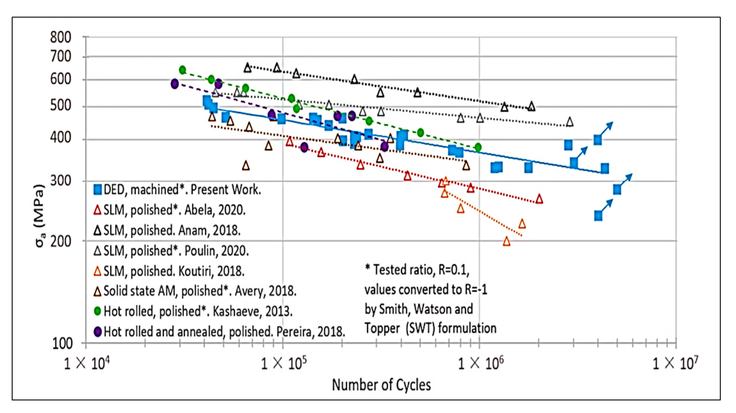
In a more recent study, F. K. Fiorentin and co-workers assessed the fatigue behavior of DLD IN625 using the standard ASTM fatigue test method and presented a methodology of testing small-sized specimens rather than standard dog-bone-shaped fatigue testing samples, supported by a numerical model developed and validated by experimental data for stress calculation. The results obtained by the small size- specimens were found in reasonably good agreement with the results obtained using standard test samples, thus validating the opted method. A comparison of S-N property data at load ratio (R) = −1 with previous works on AM IN625 showed (Figure 14) that the DLD IN625 sample (only machined, not polished) had better fatigue properties than three out of five additively manufactured builds, two out of which were manufactured using SLM and samples were in polished condition. Since the literature data were obtained for different stress R-ratios, the results were compared using the Smith–Watson–Topper mean stress correction method. The DLD IN625 presented good fatigue performance, being able to bear a hundred-thousand cycles in a stress range beyond its yield stress (for an R = 0.1) [50].

Thermal–Mechanical Fatigue Resistance of DLD IN625

Thermal–mechanical fatigue (TMF) is a specific type of fatigue that occurs when materials are subjected to simultaneous cyclic loads combined with high cyclic temperatures. In demanding engineering applications, e.g., jet engine turbine blades working at high-temperature ranges and varying mechanical loads, the role of TMF becomes increasingly important. During TMF, three main damage mechanisms—fatigue, oxidation, and creep—are frequently encountered. These mechanisms may act alone or in combination with test circumstances, such as maximum and minimum temperatures, temperature amplitude, total strain amplitude, test frequency, the phase angle between temperature, and strain, dwell duration, or environmental factors.
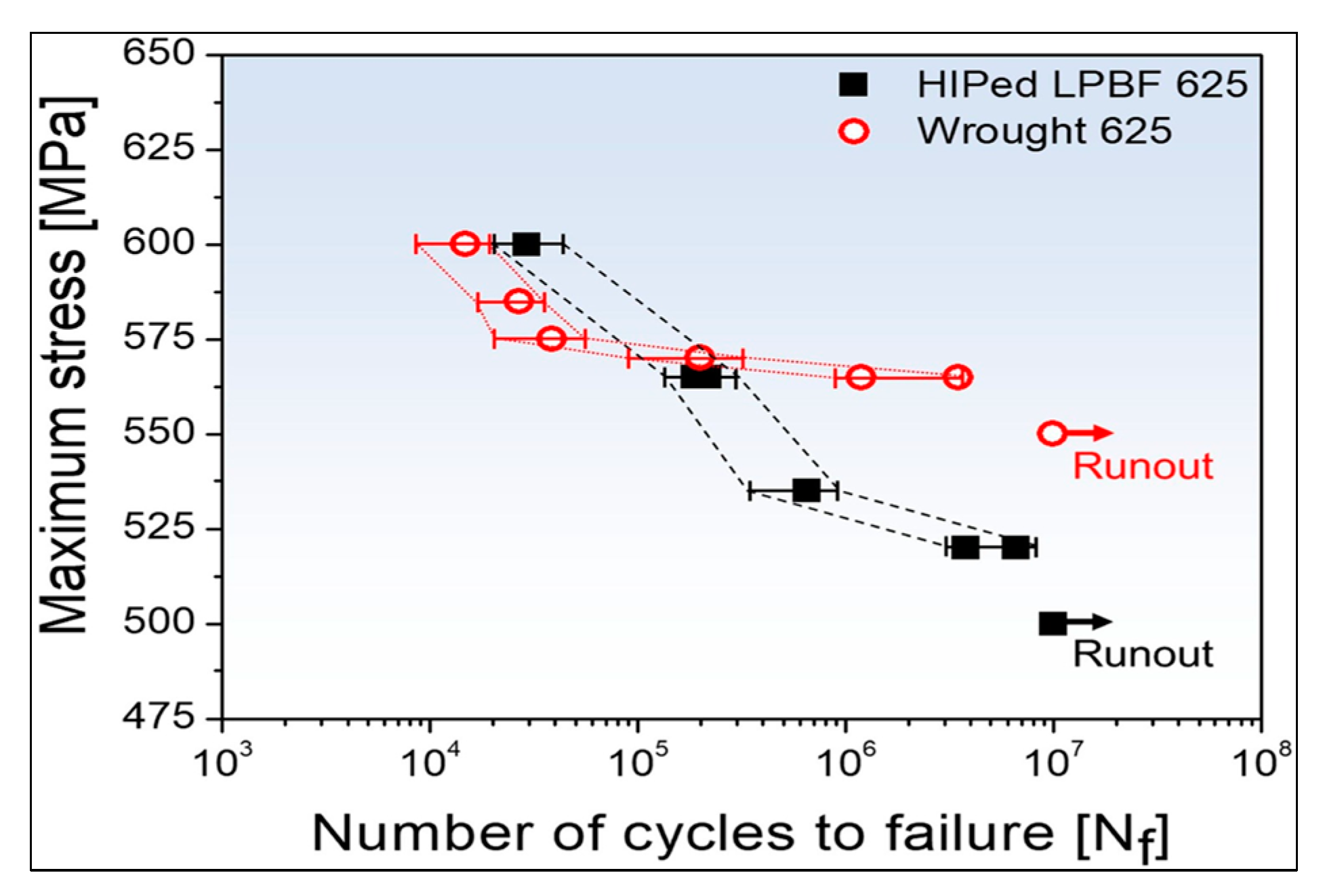
No such study has been reported for AM IN625, which typically lies within the defined scope of ASTM E2368 (standard for thermomechanical fatigue testing) materials. However, Kyu-Sik Kim et al. studied the high-temperature tensile and high cycle fatigue behavior of LPBF IN625 at high temperatures (650 °C) and compared the results with wrought IN625 in similar test conditions [51]. The LPBF IN625 was stress-relieved (800 °C, 1 h) and hot isostatic pressed (HIP, 1175 °C, 150 MPa, argon environment, 3 h) afterward. Wrought IN625 in solution was annealed at 1100 °C for 1 h. LPBF (HIPed) IN625 had similar microstructures to those of wrought 625 manufactured with conventional methods with almost identical grain size. Wrought IN625 presented fine carbide distribution, and Al2O3 and TiN precipitates were found in LPBF (HiPed) IN625 [51]. Although LPBF (HiPed) IN625 showed higher mechanical properties than wrought IN625 during a room-temperature tensile test, during high-temperature tensile testing, the elongation of LPBF (HiPed) was substantially compromised despite having the same yield strength. The high-temperature fatigue limits (maximum stress that does not result in fracture up to 1 × 10⁷ cycles) for LPBF (HIPed) IN625 and wrought IN625 were 550 MPa and 500 MPa, respectively [51]. At stress lower than 560 MPa (or fatigue life of fewer than 105 cycles), wrought IN625 had relatively better fatigue properties, while LPBF (HIPed) IN625 had better fatigue properties in higher stress range (Figure 15) [51].
At 650 °C, carbides in wrought IN625 undergo premature fracture under high stresses, promoting fatigue crack initiation, which results in reduced fatigue life. In LPBF (HIPed) IN625, high sulfur content is suggested as the most likely cause of high-temperature embrittlement [51]. Thus, feedstock powders with an even lower concentration of impurities (such as sulfur) may result in a more fatigue-resistant build using LPBF combined with the HIP process. No studies have been reported on thermomechanical fatigue testing of DLD-IN625 composites.

6. Effect of Laser/Powder Interaction

The laser energy interacts with the powder jet before it reaches the substrate, with some energy being absorbed by the powder particles and the other being reflected [52]. In the DED process, a fraction of the total heat energy is consumed in heating the powder particles after emerging from the nozzle and traveling through the beam. The energy absorbed by in-flight powder particles depends on the gas flow rate, the powders’ material properties, laser power density, and laser/powder interaction time or residence time [52]. A small molten pool is produced due to the residual beam energy impinging on the deposit surface. The amount of energy absorbed by the substrate is further influenced by the shielding gas, deposit geometry, and beam properties. The volumetric heat source with a modified Gaussian distribution (shown below) can be used to represent the heat source in the DED process [52]:
P d = f P π r b 2 t l n P + 1 η P η l exp f r ¯ b 2 r 2
where f indicates the power density, P is the laser power, r is the radial distance from laser beam axis, t l is the layer thickness, η P is the percentage of energy the powder absorbed during flight, and η l is the deposit’s absorption coefficient. When the powder is solid, the absorption value is high, but after a short duration (a few milliseconds), the liquid surface begins to absorb energy by Fresnel absorption [52]. Because of this, the value of η l initially increases as the liquid layer forms but decreases after the surface melts. Depending on whether the deposit is in a liquid or solid form, the absorption coefficients for a laser beam of 1064 µm wavelength during a laser-assisted DED process using Argon as a shielding gas lie between 0.3 and 0.7 [6].
Local energy density (Ed) specifies the energy available for melting and material deposition during DED. It can be calculated by the following relation [53]:
E d = β P V d s p o t
where the total energy absorbed during melting and deposition is represented by the bulk absorption coefficient β ; P is the heat source’s power output (in watts); V stands for scanning speed (in mm/s), and d s p o t is the diameter of the spot size. It has been demonstrated through experimental measurements that the wavelength and the material being processed affect the bulk absorption coefficient for laser-based DED. According to the results of these tests, the β for laser-based DED employing a 1 kW ytterbium laser and powder feedstock was 0.37 for Inconel 625 [54].
According to the theory of dendrite growth, the preferential direction of dendritic growth is the inverse of the direction of heat flow. The highest temperature gradient is parallel to the molten pool’s boundary during the solidification process because the substrate receives the most heat from the molten pool, as shown by a schematic diagram in Figure 16a. As a result, the single track, columnar dendritic development, is tilted in the direction of scanning. However, in the case of bi-directional scanning, adjacent layers have their scanning orientation reversed, resulting in the rotated V-shaped grain morphology, as illustrated in Figure 16b [32].

7. Fabrication of Inconel 625-Based Advanced Materials Using Laser-Directed Energy Deposition

The past few years have seen an accelerated effort in the development of advanced materials based on IN625, utilizing various AM techniques, including DED. These materials can be broadly classified into metal matrix composites (MMC) and functionally graded materials (FGM). Significant investment has been made in researching various materials for AM to address the requirements of industrial sectors, such as automotive, aerospace, military, and biomedical. This section examines the IN625-based advanced materials that have recently been treated using DED technology. The impact of processing factors on the microstructure and mechanical characteristics of the processed materials is explored, highlighting the present gaps in the knowledge required to develop engineering components that can be relied on by the industry.
DLD technology has been used to process a variety of reinforcements with IN625 to produce composites and FGMs thus far, with variable degrees of effectiveness. As this would go beyond the scope of presenting major findings and correlating them with results, only DLD IN625 and IN625-based composites’ studies are discussed further to give a fair idea to the reader regarding the role of process parameters, feedstock, and its characteristics, and resultant microstructure and properties in the AM material.

7.1. IN625-Based Composites

MMCs consist of strong second-phase particles/fibers, etc., dispersed within a metallic matrix, with the primary intention being to enhance stiffness, creep, or wear resistance, etc., while maintaining toughness which presents a challenge. Several ceramic and carbon-based (graphene, carbon nanotubes) reinforcements have gained the attention of researchers and have been used for IN625 MMCs. Here, the authors are interested in discussing the ceramic reinforcements (oxides, carbides, borides, etc.) utilized and the factors influencing the modifying properties of IN625. A sound DLD composite should demonstrate a dense, mechanically and thermally stable structure with good wear resistance and electrochemical suitability to operate in its intended environments, which broadly depends on the feedstock and processing conditions.

Effect of Reinforcement on Mechanical Properties

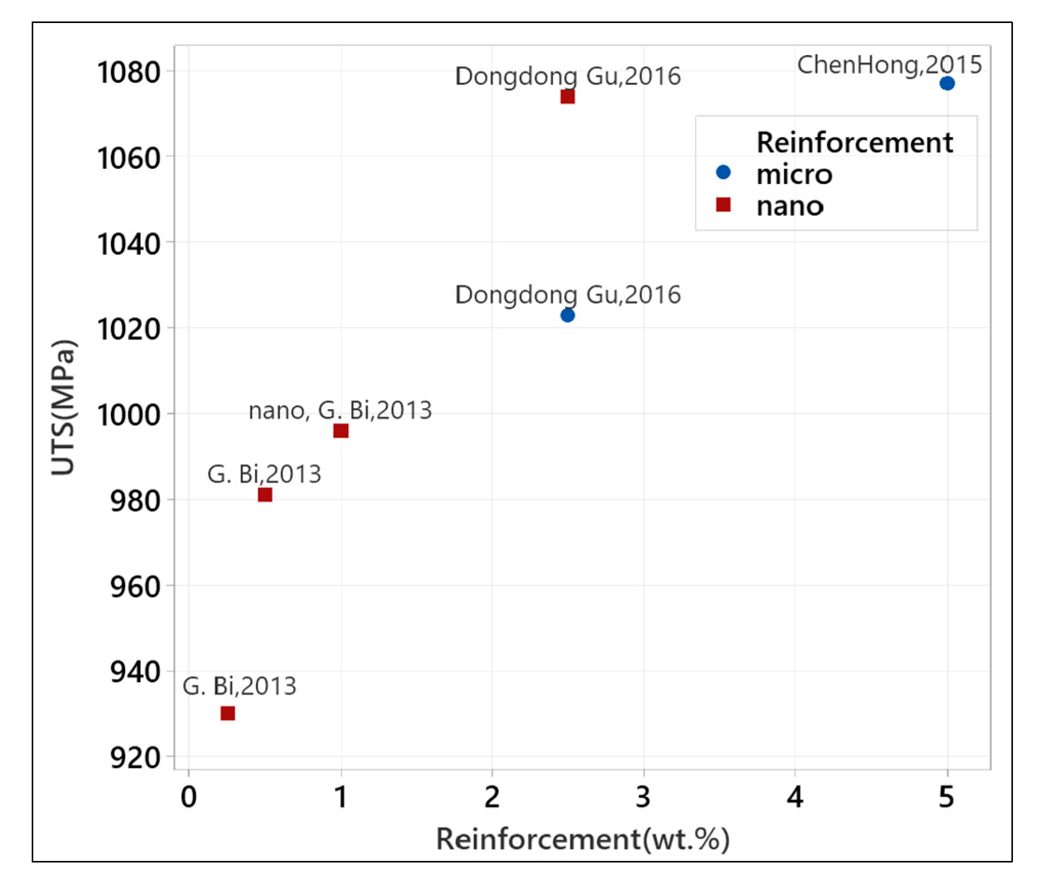
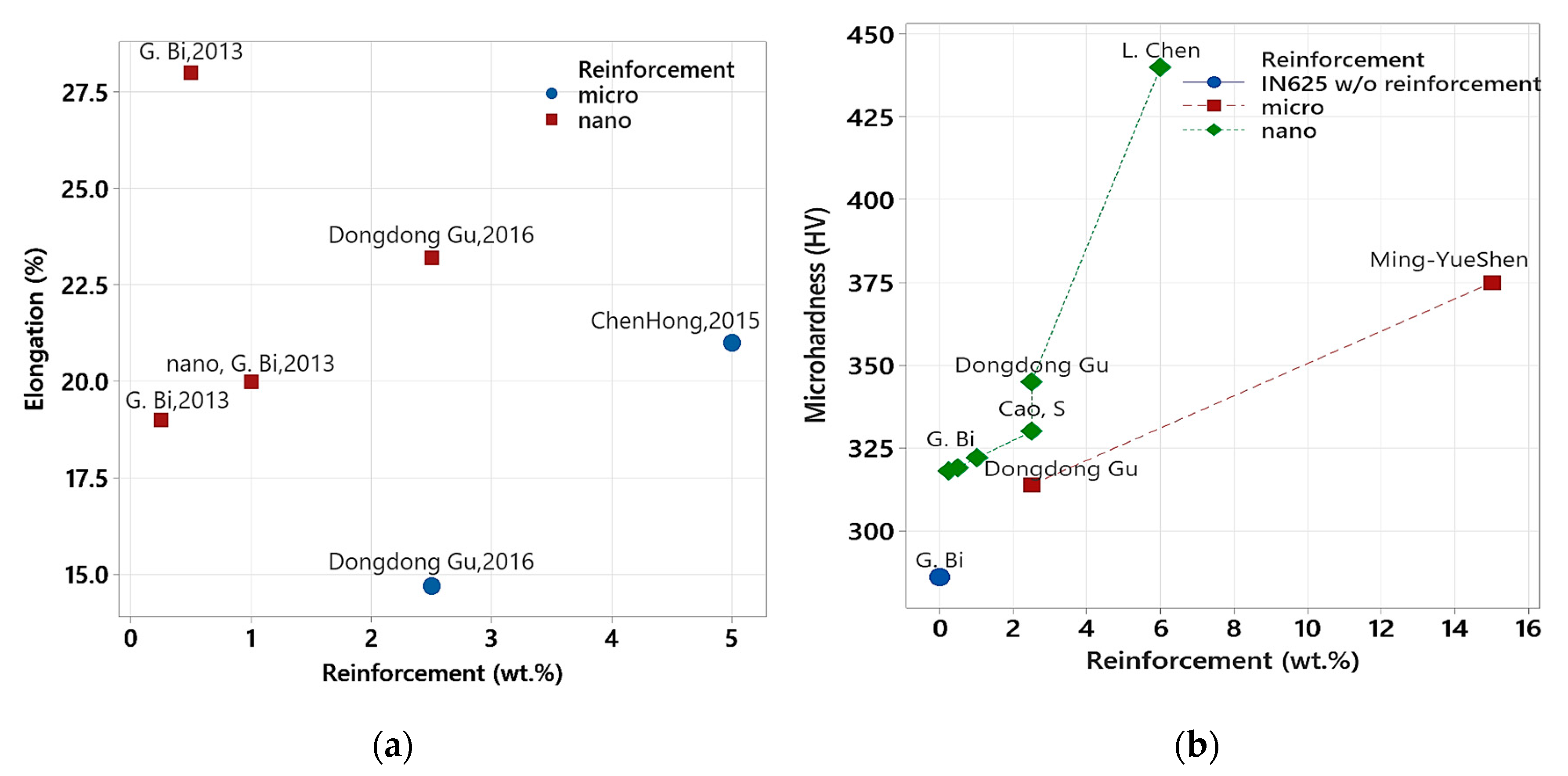
The reinforcement type, particle size, and weight fraction added to the composite significantly affect the mechanical properties of IN625 composites. A maximum of 1077 MPa tensile strength (UTS) has been reported for TiC-reinforced IN625 composites [55] using a five weight% micro-sized (5–7 µm) of TiC in the IN625 powder. However, the elongation stood at 23%. In contrast, G. Bi. [56] was able to achieve a UTS of 996 MPa with nano-scaled ultra-fine (0.08–0.15 µm) powder, which implies the effect of an increased surface area of the reinforcement particles and refinement of the microstructure leading to an increase in the strength of the material. Dondong used a similar weight% (3.5%) of micro- and nano-sized TiC reinforcements in IN625 to compare the effect of reinforcement size. The mechanical testing results showed a more pronounced increase in UTS with nano-sized particles as compared to micro-sized particles using an equal weight% of reinforcements (see Figure 17). The TiC/IN625 composite showed a lesser ductility loss with nano-TiC particles, achieving 23% elongation compared to 15% with the same weight% of micro-sized particles [57] (see Figure 18).
Intuitively, as observed in the case of UTS (Figure 17), the microhardness of TiC/IN625 composites also increased with the increasing weight fraction of reinforcement particles (either micro or nanosized), Figure 18. The wear resistance of the TiC/IN625 DLD composite has also been reported to increase with an increasing weight fraction of reinforcement particles (Figure 19). However, the addition of nano-scaled reinforcement particles imparted a distinctly higher microhardness and wear resistance than micro-scaled reinforcement particles by the addition of an equivalent or even lesser weight fraction of reinforcement due to superior grain refinement strengthening [56].
Ming-YueShen et al. used relatively larger sized (35–135 μm) TiC reinforcement in IN625 (75–250 μm) for DLD with much less rigorous mechanical mixing (30 min. In a reagent bottle). The microstructure was columnar dendritic with well-developed secondary dendrites and showed agglomeration to some extent.
The IN625/TiC presented a 50% increase in Brinell hardness over DLD IN625. Although having the same tensile strength as IN625, the DLD-IN625/TiC showed lower toughness and ductility. The partial melting and incorporation of TiC promote the formation of Ti, Mo, and Nb carbides [60]. Table 2 provides a summary of works by researchers using various reinforcements with IN625 for DLD, their powder mixing conditions, and associated outcomes.
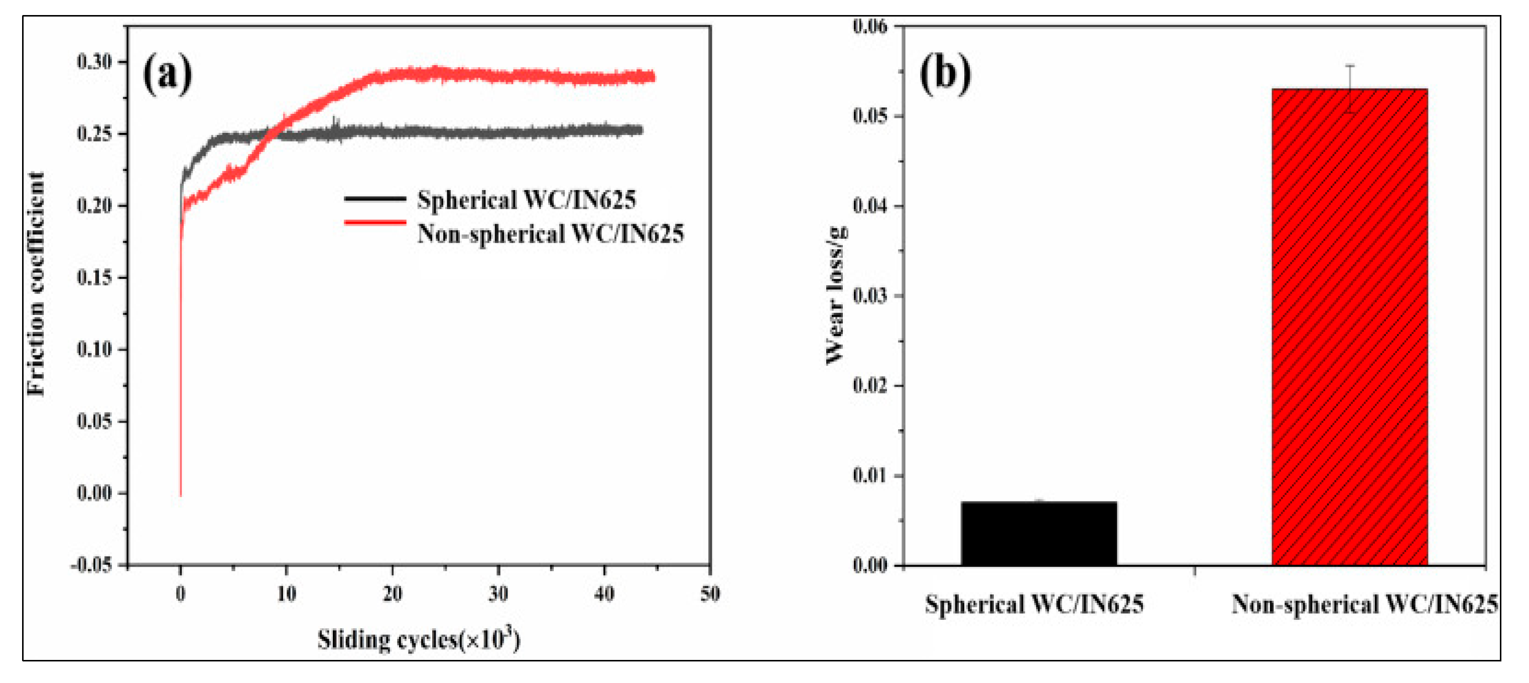
In another study on the DLD of WC (100–200 µm, 60 wt.%)/IN625, Damian Janicki et al. assessed the effect of the shape of WC reinforcement particles on the erosion properties of a WC/IN625 composite by using angular and spherical-shaped WC particles. The irregularly shaped WC reinforcement particles demonstrated mechanical interlocking in the matrix, providing higher erosion resistance to both normal and oblique impacts [64]. A more recent study on WC/IN625 concluded that irregularly shaped (non-spherical) particles offered as high as an ~8-times higher wear resistance compared to a spherical WC particles/IN625 composite by DLD, as shown in Figure 20 [65].
The yield strength of the deposited alloy can be represented as a combination of strength(s) derived from different mechanisms, as presented below:
σ y = σ 0 + Δ s s σ + Δ σ D + Δ σ b
where σ 0 is the yield strength for Nickel, Δ s s σ is the solid solution strengthening contribution due to solid-solution elements in the γ-matrix up in the sample, Δ σ D is the strength imparted by the grain-boundary strengthening mechanism, and Δ σ b is the strength contribution due to a dislocation pile-up. Mathematical relations for these strength contributions are well established in scientific literature, which are presented below [66,67]:
Δ s s σ = Σ i α i 2 C i 1 2
Δ D = K y d m 1 2
Δ b = B b ρ 1 2 G
where αi is the strengthening coefficient of ith element, Ci is the concentration of that element; Ky is the constant coefficient for the nickel-based superalloy (710 MPa·μm1/2), dm is the average grain size; B is the coefficient of proportionality, b is the Burgers vector, ρ is the dislocation density, and G is the shear modulus.
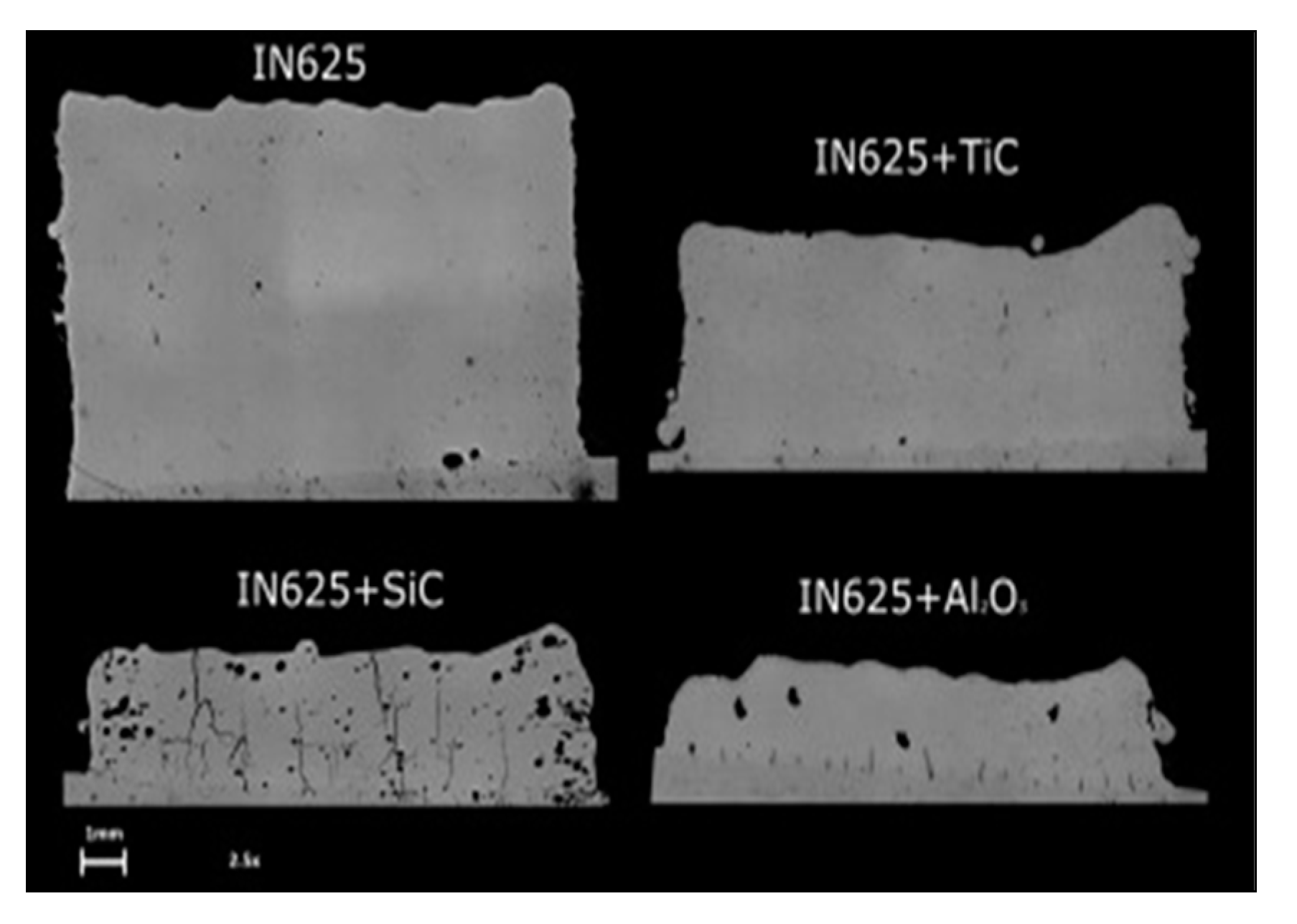
Al2O3 and SiC have also been used as reinforcements in IN625. However, the DLD results were not promising. As illustrated in Figure 21, a SiC reinforced build showed numerous cracks, and an Al2O3 reinforced IN625 build was found to deposit unevenly, to such an extent that the coaxial nozzle track was obstructed with the crust of the deposited bead [68]. Figure 21 presents the X-section of these DLD builds, wherein such defects did not form in the TiC-IN625 composite using similar processing conditions.

7.2. Effect of Mixing

The mixing technique adopted prior to the processing of MMCs substantially affects the quality of the deposit and the overall build’s properties. K. Bazaleeva et al. compared the IN625/TiC built by simultaneously feeding IN625-TiC powders through different nozzles, IN625-TiC powders mixed by a gravitational mixer, and the IN625-TiC powder mixed by ball milling. IN625-TiC powders mixed by a gravitational mixer presented two distinct zones upon DLD, labelled I (small carbide distributed uniformly) and II (dendritic carbides distributed in matrix) in Figure 22b. It was only possible to deposit a crack-free IN625/TiC composite after ball-milling the IN625-TiC powder together, as shown in Figure 22c [69].

7.3. Effect of Reinforcement on Microstructure

Different reinforcements, such as carbides, borides, and oxides, have been attempted as a reinforcement to IN625 in DLD processing. TiC has most frequently been utilized with IN625 for the DLD of IN625/TiC composites, which tends to provide the necessary undercooling for secondary dendrite growth. The degree of undercooling (difference between the equilibrium liquidus temperature and the dendrite tip temperature) is the driving force for dendritic growth [6]. The formation of well-developed secondary dendrite arms of the columnar dendrite is facilitated by a greater degree of undercooling, which can be further explained by [58]:
d = β(Vc)−1/3
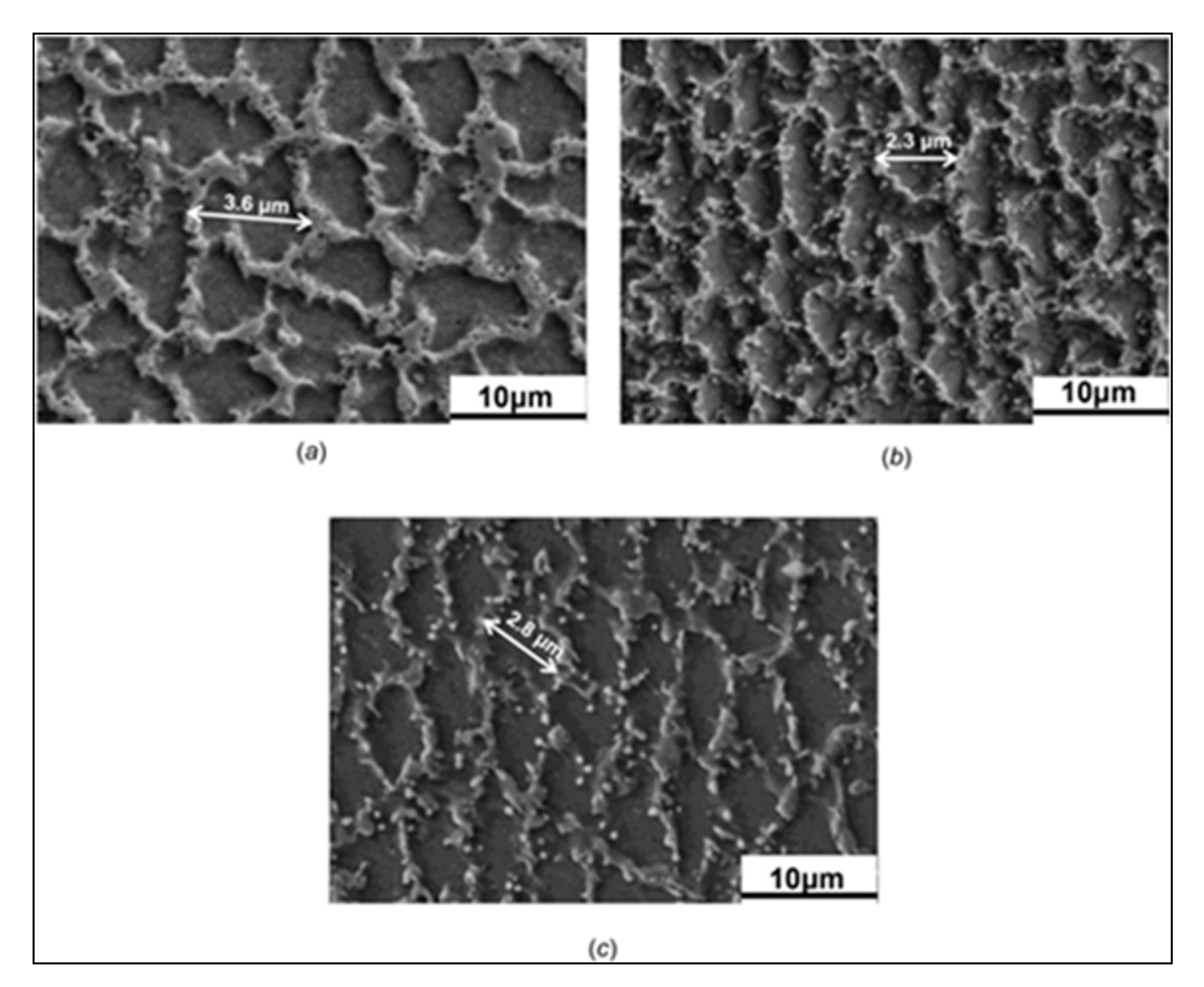
where d is the dendrite arm spacing (DAS), Vc is the cooling rate, and β is the coefficient. Equation (7) shows that a higher cooling rate results in a small DAS. Dongdong Gu reported a decrease in secondary dendrite arm spacing (SDAS) by DLD of un-reinforced IN625, micro-TiC, and nano-TiC reinforced IN625 composites with an SDAS of 3.6, 2.8, and 2.3 µm, respectively [57], as shown in Figure 23. The presence of TiC particles serves as a nucleation site for the heterogeneous nucleation of the γ-phase. The two competing processes, i.e., nucleation and grain growth, determine the final grain size [70]. The TiC particles tend to impede grain growth, playing an effective role in grain refinement of the resulting microstructure. Therefore, the dendrites of the Ni–Cr matrix were quite refined in DLD nano-TiC-IN625 [57].

8. Oxidation Resistance of DLD IN625 Composites

Chen Hong et al. studied the effect of different weight percentages (2.5 and 5 wt.%) of TiC reinforcement in IN625 on the oxidation resistance of the resulting composites produced by DLD. They conducted oxidation resistance tests at 600, 800, and 1000 °C for 100 h in air. The composite of 5 wt.% of TiC showed the best oxidation resistance with the least mass gain (0.3233 mg·cm−2). The IN625–5 wt.% TiC showed excellent oxidation resistance up to 800 °C (see Figure 24) [71]. The oxidized layer mainly consisted of Cr2O3 and TiO2, whereas the composite was severely oxidized on exposure to 1000 °C.

9. Corrosion Resistance of DLD IN625 Composites

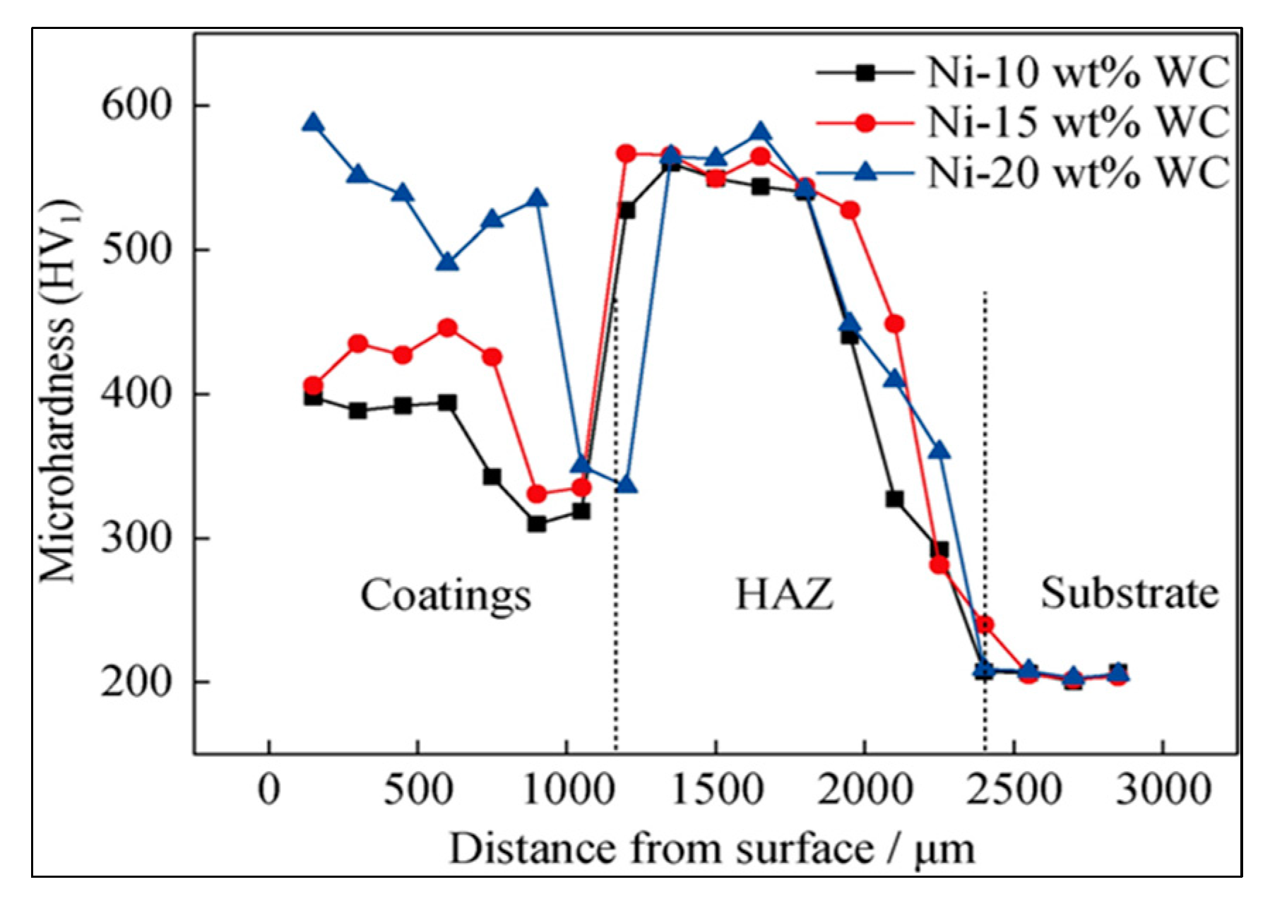
The outstanding corrosion resistance of IN625 has attracted the attention of researchers because it imparts corrosion resistance to relatively less expensive structural materials using the DLD technique. IN625-WC composite coatings were deposited on a 2Cr13 steel substrate using DLD by Zhi-Hua Tian et al. using 10–20 wt.% of WC reinforcement to impart wear and corrosion resistance, respectively, simultaneously. The best corrosion resistance and substantial increase in hardness (compared to the substrate) were observed using a 10 wt.% WC/IN625 powder mixture for DLD on 2Cr13 steel. The microstructure was mainly composed of γ-(Ni, Fe), M23C6, and NbC. Figure 25 presents the dynamic potential polarization curves for 2Cr13 and IN625-WC-composite coatings in 0.5 mol.L−1 HCl solution [72]. Figure 26 presents the hardness of composites vs. substrate, which shows a considerable decline in hardness around the heat-affected zone, necessitating a thick multi-layer pore-free coating for practical application. However, in an earlier study on the DLD of IN625-WC, J. Huebner et al. concluded that the addition of fine (0.54 µm) WC up to 20 wt.% does not significantly change the hardness of the composite, increasing it to approximately 400 HV [73]. The difference between the two studies may have resulted due to reinforcement of different particle sizes (4–7 µm vs. 0.54 µm) and power input (2400 W vs. 320 W).
A recent study using DLD processing by Wanlu Li et al. reported that composite cladding with spherical IN625-WC gave better corrosion resistance than irregularly shaped WC particles in IN625, having a 1.18-times higher polarization resistance after immersion in 3.5% NaCl solution for 60 min [65].

10. Conclusions and Recommendations

  • Rapid solidification in direct laser deposition of Inconel 625 essentially produces columnar dendritic structures, which results in anisotropic mechanical properties. A suitable additive reinforcement that may promote equiaxed grain growth could help eliminate or reduce the anisotropy in the resulting structure.
  • The mechanical testing results showed a more pronounced increase in UTS with nano-sized particles as compared to micro-sized particles using equal weight % of reinforcements. An even dispersion of finer (nano-sized) particles will likely enhance the strength by dislocation pinning. However, nano-sized particles can agglomerate in resulting builds. A higher energy input has resulted in better dispersion of fine reinforcement particles throughout the matrix.
  • The difference in strength along the horizontal direction (XY) and build (Z) direction of DLD IN625 can be attributed to the difference in grain boundary strength arising due to columnar microstructure. The difference in the microplastic strain along the horizontal (XY) direction and build (Z) direction arising due to the distribution of Laves phase particles results in a lower ductility in the horizontal direction as compared to the vertical direction in typical columnar dendritic builds of IN625.
  • The ductility of Direct laser deposited IN625 is still lower than that of its wrought counterpart. A strategy to eliminate the Laves phases or modify the distribution and morphology of Laves phase is likely to enhance the ductility in DLD IN625 builds and may also result in better creep resistance. Microstructural modification by laser deposition parameters, scanning strategies, and subsequent heat treatments may be explored further to improve ductility and toughness. In-situ alloying may also prove helpful in this regard.

11. Future Research Directions and Prospects

  • Process optimization: Future research could focus on optimizing the process parameters, such as laser power, layer thickness, powder flow rate, and scanning speed, to achieve lower porosity and higher deposition efficiency in DLD of IN625.
  • Aerospace and defense: To utilize the DLD-IN625 for aerospace applications, high-temperature creep testing and thermomechanical testing data of DLD-IN625 are required, which necessitates further studies in this domain. IN625 and its composites could find significant applications, such as the manufacturing of gas turbine components, rocket engine parts, and heat exchangers.
  • Material development and multi-material deposition: The potential of IN625-based composites can be further explored by studying oxides, carbides, and borides which have not been utilized/studied in detail as reinforcements with IN625 yet. More uniform mixing before deposition and optimization of laser processing parameters to achieve a homogenous distribution across the DLD build can pave the way for the industrial utility of IN625-based composites. The ability of DLD to deposit multiple materials in a single build could lead to the development of IN625-based functionally graded materials, which could exhibit tailored thermal, mechanical, and chemical properties for specific applications.

Author Contributions

Conceptualization, O.E. and F.Z.; data collection, F.Z. and J.C.; writing—original draft preparation, F.Z. and J.C.; writing—review and editing, O.E., M.V. and A.R.; supervision, O.E., M.V. and A.R. All authors have read and agreed to the published version of the manuscript.

Funding

This research received no external funding.

Data Availability Statement

The data supporting the findings of this study are available within the article.

Conflicts of Interest

The authors declare no conflict of interest.

Appendix A

Table A1. TiC reinforced IN625-based composites by DLD (Reference sources for Figure 3).
Particle Size (µm)Matrix wt.%Rein. Wt.%UTSel.%G.L/Width or G.L/Dia RatioHVSource
20–45/0.08–0.1599.750.25930194/1318[56]
20–45/0.08–0.1599.50.5981284/1319[56]
20–45/0.08–0.15991996204/1322[56]
45–95/5–79551077214/1xx[55]
15–45/2–597.52.5102314.73/1314[57]
15–45/0.0497.52.5107423.23/1345[57]

References

  1. Davis, J.R. 6.4.1 General Oxidation. In ASM Specialty Handbook—Nickel, Cobalt, and Their Alloys; ASM International: Materials Park, OH, USA, 2000; p. 86. [Google Scholar]
  2. Kutz, M. Mechanical Engineers’ Handbook—Materials and Engineering Mechanics, 4th ed.; John Wiley & Sons: Hoboken, NJ, USA, 2015. [Google Scholar]
  3. Zhu, D.; Zhang, X.; Ding, H. Tool wear characteristics in machining of nickel-based superalloys. Int. J. Mach. Tools Manuf. 2013, 64, 60–77. [Google Scholar] [CrossRef]
  4. Thakur, A.; Gangopadhyay, S. State-of-the-art in surface integrity in machining of nickel-based super alloys. Int. J. Mach. Tools Manuf. 2016, 100, 25–54. [Google Scholar] [CrossRef]
  5. Bourell, D.L.; Frazier, W.; Kuhn, H.; Seifi, M. 1. Introduction to Additive Manufacturing. In ASM Handbook®, Volume 24—Additive Manufacturing Processes; ASM International: Materials Park, OH, USA, 2020; pp. 3–10. [Google Scholar]
  6. DebRoy, T.; Wei, H.L.; Zuback, J.S.; Mukherjee, T.; Elmer, J.W.; Milewski, J.O.; Beese, A.M.; Wilson-Heid, A.; De, A.; Zhang, W. Additive manufacturing of metallic components—Process, structure and properties. Prog. Mater. Sci. 2018, 92, 112–224. [Google Scholar] [CrossRef]
  7. Pratheesh Kumar, S.; Elangovan, S.; Mohanraj, R.; Ramakrishna, J.R. A review on properties of Inconel 625 and Inconel 718 fabricated using direct energy deposition. Mater. Today: Proc. 2021, 46, 7892–7906. [Google Scholar] [CrossRef]
  8. Tan, C.; Weng, F.; Sui, S.; Chew, Y.; Bi, G. Progress and perspectives in laser additive manufacturing of key aeroengine materials. Int. J. Mach. Tools Manuf. 2021, 170, 103804. [Google Scholar] [CrossRef]
  9. Moeinfar, K.; Khodabakhshi, F.; Kashani-bozorg, S.F.; Mohammadi, M.; Gerlich, A.P. A review on metallurgical aspects of laser additive manufacturing (LAM): Stainless steels, nickel superalloys, and titanium alloys. J. Mater. Res. Technol. 2022, 16, 1029–1068. [Google Scholar] [CrossRef]
  10. Karmuhilan, M.; Kumanan, S. A Review on Additive Manufacturing Processes of Inconel 625. J. Mater. Eng. Perform. 2022, 31, 2583–2592. [Google Scholar] [CrossRef]
  11. Srinivasan, D.; Ananth, K. Recent Advances in Alloy Development for Metal Additive Manufacturing in Gas Turbine/Aerospace Applications: A Review. J. Indian Inst. Sci. 2022, 102, 311–349. [Google Scholar] [CrossRef]
  12. Zuback, J.S.; DebRoy, T. The Hardness of Additively Manufactured Alloys. Materials 2018, 11, 2070. [Google Scholar] [CrossRef] [PubMed]
  13. Sundararaman, M.; Mukhopadhyay, P.; Banerjee, S. Precipitation of the δ-Ni3Nb phase in two nickel base superalloys. Metall. Trans. A 1988, 19, 453–465. [Google Scholar] [CrossRef]
  14. De Oliveira, M.M.; Couto, A.A.; Almeida, G.F.C.; Reis, D.A.P.; de Lima, N.B.; Baldan, R. Mechanical Behavior of Inconel 625 at Elevated Temperatures. Metals 2019, 9, 301. [Google Scholar] [CrossRef]
  15. Han, F.F.; Zhou, B.M.; Huang, H.F.; Leng, B.; Lu, Y.L.; Dong, J.S.; Li, Z.J.; Zhou, X.T. The tensile behavior of GH3535 superalloy at elevated temperature. Mater. Chem. Phys. 2016, 182, 22–31. [Google Scholar] [CrossRef]
  16. Tian, C.; Cui, C.; Xu, L.; Gu, Y.; Sun, X. Dynamic Strain Aging in a Newly Developed Ni–Co-Base Superalloy with Low Stacking Fault Energy. J. Mater. Sci. Technol. 2013, 29, 873–878. [Google Scholar] [CrossRef]
  17. Smithells, C.J. Metals Reference Book, 7th ed.; Butterworths: London, UK, 1976. [Google Scholar]
  18. Pelloux, R.; Grant, N. Solid Solutions And Second Phase Strengthening of Nickel Alloys at High And Low Temperatures; Massachusetts Instutute of Technology, Deptarmetn of Metallurgy: Cambridge, MA, USA, 1959. [Google Scholar]
  19. Jena, A.K.; Chaturvedi, M.C. The role of alloying elements in the design of nickel-base superalloys. J. Mater. Sci. 1984, 19, 3121–3139. [Google Scholar] [CrossRef]
  20. Totten, G.E. 23.1 Wrought Nickel Alloys. In ASM Handbook Volume 4E—Heat Treating of Nonferrous Alloys; ASM International: Materials Park, OH, USA, 2016; p. 427. [Google Scholar]
  21. Semiatin, S.L. ASM Handbook: Volume 14A—Metalworking: Bulk Forming; ASM International: Materials Park, OH, USA, 2005; p. 329. [Google Scholar]
  22. Slotwinski, J.; Slotwinski, J.; Moylan, S. Applicability of Existing Materials Testing Standards for Additive Manufacturing Materials; US Department of Commerce, National Institute of Standards and Technology: Gaithersburg, MD, USA, 2014. [Google Scholar]
  23. Chen, F.; Wang, Q.; Zhang, C.; Huang, Z.; Jia, M.; Shen, Q. Microstructures and mechanical behaviors of additive manufactured Inconel 625 alloys via selective laser melting and laser engineered net shaping. J. Alloys Compd. 2022, 917, 165572. [Google Scholar] [CrossRef]
  24. Nguejio, J.; Szmytka, F.; Hallais, S.; Tanguy, A.; Nardone, S.; Godino Martinez, M. Comparison of microstructure features and mechanical properties for additive manufactured and wrought nickel alloys 625. Mater. Sci. Eng. A 2019, 764, 138214. [Google Scholar] [CrossRef]
  25. Ferreira, A.A.; Reis, A.R.; Amaral, R.L.; Cruz, J.M.; Romio, P.C.; Seabra, J.O.; Vieira, M.F. Mechanical and microstructural characterisation of bulk Inconel 625 produced by direct laser deposition. Mater. Sci. Eng. A 2022, 838, 142777. [Google Scholar] [CrossRef]
  26. Khayat, Z.R.; Palmer, T.A. Impact of iron composition on the properties of an additively manufactured solid solution strengthened nickel base alloy. Mater. Sci. Eng. A 2018, 718, 123–134. [Google Scholar] [CrossRef]
  27. ASTM F3056; Standard Specification for Additive Manufacturing Nickel Alloy (UNS N06625) with Powder Bed Fusion. ASTM: West Conshohocken, PA, USA, 2021; p. 8. [CrossRef]
  28. Rombouts, M.; Maes, G.; Mertens, M.; Hendrix, W. Laser metal deposition of Inconel 625: Microstructure and mechanical properties. J. Laser Appl. 2012, 24, 052007. [Google Scholar] [CrossRef]
  29. ASTM B443; Standard Specification for Nickel-Chromium-Molybdenum-Columbium Alloy and Nickel-Chromium-Molybdenum-Silicon Alloy Plate, Sheet, and Strip. ASTM: West Conshohocken, PA, USA, 2019; p. 8. [CrossRef]
  30. Hu, Y.L.; Li, Y.L.; Zhang, S.Y.; Lin, X.; Wang, Z.H.; Huang, W.D. Effect of solution temperature on static recrystallization and ductility of Inconel 625 superalloy fabricated by directed energy deposition. Mater. Sci. Eng. A 2020, 772, 138711. [Google Scholar] [CrossRef]
  31. Kreitcberg, A.; Brailovski, V.; Turenne, S. Effect of heat treatment and hot isostatic pressing on the microstructure and mechanical properties of Inconel 625 alloy processed by laser powder bed fusion. Mater. Sci. Eng. A 2017, 689, 1–10. [Google Scholar] [CrossRef]
  32. Hu, Y.; Lin, X.; Li, Y.; Ou, Y.; Gao, X.; Zhang, Q.; Li, W.; Huang, W. Microstructural evolution and anisotropic mechanical properties of Inconel 625 superalloy fabricated by directed energy deposition. J. Alloys Compd. 2021, 870, 159426. [Google Scholar] [CrossRef]
  33. Guidelines for Determining Coordinate Systems and Testing Methodologies in AM Processes; ASTM: West Conshohocken, PA, USA, 2019; p. 14. [CrossRef]
  34. Dinda, G.P.; Dasgupta, A.K.; Mazumder, J. Laser aided direct metal deposition of Inconel 625 superalloy: Microstructural evolution and thermal stability. Mater. Sci. Eng. A 2009, 509, 98–104. [Google Scholar] [CrossRef]
  35. Li, S.; Wei, Q.; Shi, Y.; Zhu, Z.; Zhang, D. Microstructure Characteristics of Inconel 625 Superalloy Manufactured by Selective Laser Melting. J. Mater. Sci. Technol. 2015, 31, 946–952. [Google Scholar] [CrossRef]
  36. Rai, S.K.; Kumar, A.; Shankar, V.; Jayakumar, T.; Bhanu Sankara Rao, K.; Raj, B. Characterization of microstructures in Inconel 625 using X-ray diffraction peak broadening and lattice parameter measurements. Scr. Mater. 2004, 51, 59–63. [Google Scholar] [CrossRef]
  37. Luna, V.; Trujillo, L.; Gamon, A.; Arrieta, E.; Murr, L.E.; Wicker, R.B.; Katsarelis, C.; Gradl, P.R.; Medina, F. Comprehensive and Comparative Heat Treatment of Additively Manufactured Inconel 625 Alloy and Corresponding Microstructures and Mechanical Properties. J. Manuf. Mater. Process. 2022, 6, 107. [Google Scholar] [CrossRef]
  38. Qin, L.; Chen, C.; Zhang, M.; Yan, K.; Cheng, G.; Jing, H.; Wang, X. The microstructure and mechanical properties of deposited-IN625 by laser additive manufacturing. Rapid Prototyp. J. 2017, 23, 1119–1129. [Google Scholar] [CrossRef]
  39. Xingcheng, W.; Chen, C.; Qin, L.; Zhang, M. Microstructure Evolution and Mechanical Behavior of Inconel 625 Produced Using Direct Laser Metal Deposition. Phys. Met. Metallogr. 2021, 122, 896–907. [Google Scholar] [CrossRef]
  40. Davis, J.R. 3.3 References. In ASM Specialty Handbook—Nickel, Cobalt, and Their Alloys; ASM International: Materials Park, OH, USA, 2000; p. 5. [Google Scholar]
  41. Floreen, S.; Fuchs, G.E.; Yang, W.J.S. The Metallurgy of Alloy 625. In Superalloys; Knolls Atomic Power Laboratory: Niskayuna, NY, USA, 1994; pp. 13–37. [Google Scholar]
  42. Reed, R.C. The Superalloys: Fundamentals and Applications; Cambridge University Press: Cambridge, UK, 2008. [Google Scholar]
  43. Sundararaman, M.; Mukhopadhyay, P.; Banerjee, S. Carbide precipitation in nickel base superalloys 718 and 625 and their effect on mechanical properties. Superalloys 1997, 718, 367–378. [Google Scholar]
  44. Lass, E.A.; Stoudt, M.R.; Williams, M.E.; Katz, M.B.; Levine, L.E.; Phan, T.Q.; Gnaeupel-Herold, T.H.; Ng, D.S. Formation of the Ni3Nb δ-Phase in Stress-Relieved Inconel 625 Produced via Laser Powder-Bed Fusion Additive Manufacturing. Metall. Mater. Trans. A 2017, 48, 5547–5558. [Google Scholar] [CrossRef]
  45. Stoudt, M.R.; Lass, E.; Ng, D.S.; Williams, M.E.; Zhang, F.; Campbell, C.E.; Lindwall, G.; Levine, L.E. The influence of annealing temperature and time on the formation of δ-phase in additively-manufactured Inconel 625. Metall. Mater. Trans. A 2018, 49, 3028–3037. [Google Scholar] [CrossRef]
  46. Son, K.-T.; Phan, T.Q.; Levine, L.E.; Kim, K.-S.; Lee, K.-A.; Ahlfors, M.; Kassner, M.E. The creep and fracture properties of additively manufactured inconel 625. Materialia 2021, 15, 101021. [Google Scholar] [CrossRef]
  47. Poulin, J.-R.; Kreitcberg, A.; Terriault, P.; Brailovski, V. Long fatigue crack propagation behavior of laser powder bed-fused inconel 625 with intentionally-seeded porosity. Int. J. Fatigue 2019, 127, 144–156. [Google Scholar] [CrossRef]
  48. Poulin, J.-R.; Kreitcberg, A.; Terriault, P.; Brailovski, V. Fatigue strength prediction of laser powder bed fusion processed Inconel 625 specimens with intentionally-seeded porosity: Feasibility study. Int. J. Fatigue 2020, 132, 105394. [Google Scholar] [CrossRef]
  49. Theriault, A.; Xue, L.; Dryden, J.R. Fatigue behavior of laser consolidated IN-625 at room and elevated temperatures. Mater. Sci. Eng. A 2009, 516, 217–225. [Google Scholar] [CrossRef]
  50. Klein Fiorentin, F.; Maciel, D.; Gil, J.; Figueiredo, M.; Berto, F.; de Jesus, A. Fatigue Assessment of Inconel 625 Produced by Directed Energy Deposition from Miniaturized Specimens. Metals 2022, 12, 156. [Google Scholar] [CrossRef]
  51. Kim, K.-S.; Kang, T.-H.; Kassner, M.E.; Son, K.-T.; Lee, K.-A. High-temperature tensile and high cycle fatigue properties of inconel 625 alloy manufactured by laser powder bed fusion. Addit. Manuf. 2020, 35, 101377. [Google Scholar] [CrossRef]
  52. Manvatkar, V.; De, A.; DebRoy, T. Heat transfer and material flow during laser assisted multi-layer additive manufacturing. J. Appl. Phys. 2014, 116, 124905. [Google Scholar] [CrossRef]
  53. Bourell, D.L.; Frazier, W.; Kuhn, H.; Seifi, M. 20.4.1 Fundamental Process Parameters. In ASM Handbook®, Volume 24—Additive Manufacturing Processes; ASM International: Materials Park, OH, USA, 2020; pp. 225–226. [Google Scholar]
  54. Bourell, D.L.; Frazier, W.; Kuhn, H.; Seifi, M. ASM Handbook®, Volume 24—Additive Manufacturing Processes; ASM International: Materials Park, OH, USA, 2020. [Google Scholar]
  55. Hong, C.; Gu, D.; Dai, D.; Alkhayat, M.; Urban, W.; Yuan, P.; Cao, S.; Gasser, A.; Weisheit, A.; Kelbassa, I.; et al. Laser additive manufacturing of ultrafine TiC particle reinforced Inconel 625 based composite parts: Tailored microstructures and enhanced performance. Mater. Sci. Eng. A 2015, 635, 118–128. [Google Scholar] [CrossRef]
  56. Bi, G.; Sun, C.N.; Nai, M.L.; Wei, J. Micro-structure and Mechanical Properties of Nano-TiC Reinforced Inconel 625 Deposited using LAAM. Phys. Procedia 2013, 41, 828–834. [Google Scholar] [CrossRef]
  57. Gu, D.; Cao, S.; Lin, K. Laser Metal Deposition Additive Manufacturing of TiC Reinforced Inconel 625 Composites: Influence of the Additive TiC Particle and Its Starting Size. J. Manuf. Sci. Eng. 2016, 139, 041014. [Google Scholar] [CrossRef]
  58. Cao, S.; Gu, D. Laser metal deposition additive manufacturing of TiC/Inconel 625 nanocomposites: Relation of densification, microstructures and performance. J. Mater. Res. 2015, 30, 3616–3628. [Google Scholar] [CrossRef]
  59. Chen, L.; Sun, Y.; Li, L.; Ren, Y.; Ren, X. In situ TiC/Inconel 625 nanocomposites fabricated by selective laser melting: Densification behavior, microstructure evolution, and wear properties. Appl. Surf. Sci. 2020, 518, 145981. [Google Scholar] [CrossRef]
  60. Shen, M.-Y.; Tian, X.-J.; Liu, D.; Tang, H.-B.; Cheng, X. Microstructure and fracture behavior of TiC particles reinforced Inconel 625 composites prepared by laser additive manufacturing. J. Alloys Compd. 2018, 734, 188–195. [Google Scholar] [CrossRef]
  61. Jiang, D.; Hong, C.; Zhong, M.; Alkhayat, M.; Weisheit, A.; Gasser, A.; Zhang, H.; Kelbassa, I.; Poprawe, R. Fabrication of nano-TiCp reinforced Inconel 625 composite coatings by partial dissolution of micro-TiCp through laser cladding energy input control. Surf. Coat. Technol. 2014, 249, 125–131. [Google Scholar] [CrossRef]
  62. Zhang, B.; Bi, G.; Wang, P.; Bai, J.; Chew, Y.; Nai, M.S. Microstructure and mechanical properties of Inconel 625/nano-TiB2 composite fabricated by LAAM. Mater. Des. 2016, 111, 70–79. [Google Scholar] [CrossRef]
  63. Promakhov, V.; Matveev, A.; Klimova-Korsmik, O.; Schulz, N.; Bakhmat, V.; Babaev, A.; Vorozhtsov, A. Structure and Properties of Metal-Matrix Composites Based on an Inconel 625—TiB2 System Fabricated by Additive Manufacturing. Metals 2022, 12, 525. [Google Scholar] [CrossRef]
  64. Janicki, D.; Musztyfaga, M.M. Direct Diode Laser Cladding of Inconel 625/WC Composite Coatings. Stroj. Vestn. J. Mech. Eng. 2016, 62, 10. [Google Scholar] [CrossRef]
  65. Li, W.; Di, R.; Yuan, R.; Song, H.; Lei, J. Microstructure, wear resistance and electrochemical properties of spherical/non-spherical WC reinforced Inconel 625 superalloy by laser melting deposition. J. Manuf. Process. 2022, 74, 413–422. [Google Scholar] [CrossRef]
  66. Hansen, N. Hall–Petch relation and boundary strengthening. Scr. Mater. 2004, 51, 801–806. [Google Scholar] [CrossRef]
  67. Roth, H.; Davis, C.; Thomson, R. Modeling solid solution strengthening in nickel alloys. Metall. Mater. Trans. A 1997, 28, 1329–1335. [Google Scholar] [CrossRef]
  68. Cooper, D.E.; Blundell, N.; Maggs, S.; Gibbons, G.J. Additive layer manufacture of Inconel 625 metal matrix composites, reinforcement material evaluation. J. Mater. Process. Technol. 2013, 213, 2191–2200. [Google Scholar] [CrossRef]
  69. Bazaleeva, K.; Aleksandrova, A.; Balakirev, E. Structure features of the composite materials Inconel 625/TiC, produced by LMD method. J. Phys. Conf. Ser. 2018, 1109, 012053. [Google Scholar] [CrossRef]
  70. Wilson, J.M.; Shin, Y.C. Microstructure and wear properties of laser-deposited functionally graded Inconel 690 reinforced with TiC. Surf. Coat. Technol. 2012, 207, 517–522. [Google Scholar] [CrossRef]
  71. Hong, C.; Gu, D.; Dai, D.; Cao, S.; Alkhayat, M.; Jia, Q.; Gasser, A.; Weisheit, A.; Kelbassa, I.; Zhong, M.; et al. High-temperature oxidation performance and its mechanism of TiC/Inconel 625 composites prepared by laser metal deposition additive manufacturing. J. Laser Appl. 2015, 27, S17005. [Google Scholar] [CrossRef]
  72. Tian, Z.-H.; Zhao, Y.-T.; Jiang, Y.-J.; Ren, H.-P. Microstructure and properties of Inconel 625 + WC composite coatings prepared by laser cladding. Rare Met. 2021, 40, 2281–2291. [Google Scholar] [CrossRef]
  73. Huebner, J.; Kusiński, J.; Rutkowski, P.; Kata, D. Microstructural and mechanical study of inconel 625–tungsten carbide composite coatings obtained by powder laser cladding. Arch. Metall. Mater. 2017, 2, 531–538. [Google Scholar] [CrossRef]
Figure 1. Year-wise Publications—Additive manufacturing of Inconel 625 (Web of Science).
Metals 13 00787 g001
Figure 2. Key areas addressed in the article.
Metals 13 00787 g002
Figure 3. Effect of temperature on short-term mechanical properties (tensile) of the cast (data from Ref. [1])and wrought (data from Ref. [2]) IN625.
Metals 13 00787 g003
Figure 4. Mechanical properties of DLD Inconel 625 in different orientations. (data from Refs. [23,24,25,26,27,28,29,30]).
Metals 13 00787 g004
Figure 5. Longitudinal (X-Z) section of DLD IN625. (a) Bidirectional scan, (b) unidirectional scan, B-Build direction, and S-Laser scan direction (adapted with permission from Ref. [34] 2009, Elsevier).
Metals 13 00787 g005
Figure 6. Transverse (X-Z) section of DLD AM IN625 (adapted with permission from [34] 2009, Elsevier).
Metals 13 00787 g006
Figure 7. X-Y section (horizontal section) of DLD AM IN625 (adapted with permission from Ref. [23] 2022, Elsevier).
Metals 13 00787 g007
Figure 8. EBSD analyses of the DLD Inconel 625. Inverse pole figure (IPF) of the Y-Z (transverse) section of samples printed with different laser power. (a) 270 W; (b) 300 W; (c) 330 W (adapted with permission from Ref. [24] 2019, Elsevier).
Metals 13 00787 g008
Figure 9. Effect of laser power on grain size and tensile mechanical properties (data from Ref. [37]).
Metals 13 00787 g009
Figure 10. As-deposited and annealed samples at different temperatures; the vertical cross-section (Plane B, X-Z): (a,b) without heat treatment; (c,d) 1000 °C; (e,f) 1100 °C; (g,h) 1200 °C (adapted with permission from [38] 2017, Emerald Publishing).
Metals 13 00787 g010
Figure 11. Bright-field image and its SAED pattern of ellipsoid MC carbide particles. (ac) Blocky MC carbide particles (adapted with permission from Ref. [39] 2021, Springer).
Metals 13 00787 g011
Figure 12. TEM bright field photographs, SAED patterns, and EDS element analysis results of specimens at different annealing temperatures. (a) 1000; (b) 1100; (c) 1200 °C (adapted with permission from Ref. [39] 2021, Springer).
Metals 13 00787 g012
Figure 13. Fatigue life data of IN-625 in air at 650 °C under a stress-controlled sinusoidal waveform (R = 0.1, f = 60 Hz) LC(SR) = Direct laser deposited + Stress relieved (adapted with permission from Ref. [49] 2009, Elsevier).
Metals 13 00787 g013
Figure 14. Literature comparison, S-N, R = −1(adapted from Ref. [50] 2022, MDPI).
Metals 13 00787 g014
Figure 15. Maximum stress vs. fatigue life of HIPed LPBF 625 and wrought 625 at 650 °C (adapted with permission from Ref. [51] 2020, Elsevier).
Metals 13 00787 g015
Figure 16. (a) Schematic diagram of dendritic growth in the molten pool; (b) Schematic diagram of columnar grains in the as-deposited sample (adapted with permission from Ref. [32] 2021, Elsevier).
Metals 13 00787 g016
Figure 17. Effect of the TiC reinforcement concentration and particle size on the mechanical strength of the IN625 Composite (see Appendix A for data sources).
Metals 13 00787 g017
Figure 18. Effect of TiC reinforcement concentration and particle size (a) on the ductility of the IN625 composite, (b) microhardness vs. reinforcement (See Appendix A for data sources).
Metals 13 00787 g018
Figure 19. Effect of TiC reinforcement on wear resistance of DLD IN625 (data from [57,58,59]).
Metals 13 00787 g019
Figure 20. Effect of WC reinforcement shape on (a) friction coefficient; (b) mass loss (adapted with permission from Ref. [65] 2022, Elsevier).
Metals 13 00787 g020
Figure 21. X-Section of DLD IN625(top left); IN625 + TiC (top right); IN625 + SiC (bottom left); IN625 + Al2O3 (bottom right) (adapted with permission from Ref. [68] 2013, Elsevier).
Metals 13 00787 g021
Figure 22. Microstructures of the composite materials Inconel 625/TiC obtained with a different feed of powders: (a) separate feed of powders; (b) mixing in a gravitational mixer (I—spherical crystal zone; II—dendritic crystal zone); (c) mixing in a planetary ball mill (adapted with permission from Ref. [69] 2018, IOP Publishing).
Metals 13 00787 g022
Figure 23. FE-SEM images showing the cellular microstructures in DLD-processed Inconel 625 and TiC/Inconel 625 composites. (a) Unreinforced Inconel 625; (b) Inconel 625 + nano-TiC; and (c) Inconel 625 + micro-TiC (adapted with permission from Ref. [57] 2017, ASME.
Metals 13 00787 g023
Figure 24. Isothermal-oxidation kinetics of LMD-processed Inconel 625, Inconel 625/2.5 wt.% TiC (NMMCs1), and Inconel 625/5.0 wt.% TiC (NMMCs2) parts (adapted with permission from Ref. [71] 2014, AIP Publishing).
Metals 13 00787 g024
Figure 25. Dynamic potential polarization curves of composite coatings and 2Cr13 steel in a 0.5 mol·L−1 HCl solution (adapted with permission from Ref. [72] 2021, Springer).
Metals 13 00787 g025
Figure 26. Microhardness distribution of laser cladding layers with different WC content (adapted with permission from Ref. [72] 2021, Springer).
Metals 13 00787 g026
Table 1. Variation in the lattice parameter of the DLD and wrought Inconel 625 under different heat treatments.
Manufacturing ProcessExposure Temperature & DurationInterpretation w.r.t. Phases/PrecipitatesLattice Parameter (pm)Source
DLD, as deposited---γ′/γ″/δ precipitated360.01[34]
DLD800 °C/1 hProbable partial dissolution of γ″ increases lattice constant 360.22[34]
DLD1000 °C/1 hNb comes out of the matrix, consumed by δ precipitates360.09[34]
DLD1100 °C/1 hδ precipitates dissolve in the matrix 360.34[34]
WroughtAs receivedMo, Nb within the matrix; large lattice distortion360.146[24]
Wrought600 °C/1 hγ″ precipitated; lattice constant decreased359.546[24]
Wrought900 °C/1 hstrengthening elements from precipitates are progressively dissolved back into the matrix; the lattice constant increased360.145[24]
Wrought1100 °C/1 hAlthough expected to increase, the lattice constant decreases, possibly due to the presence of carbides360.000[24]
Table 2. Mixing conditions of IN625-based DLD composites.
Matrix/Reinforcement
(Particle Size in µm)
Reinforcement wt.%
Powder Milling ConditionsMech. PropertiesOutcomeReference
UTS (MPa)Y.S.
(MPa)
Elongation
(%)
Hardness
IN625/TiC
(20–45/0.08–0.15 µm)
0.25 wt.%
0.5 wt.%
1.0 wt.%
-930
981
996
645
644
648
19
28
20
318 HV
319 HV
322 HV
Nano-TiC particles contribute to grain refinement and strengthening.[56]
IN625/TiC
(45–90/5–7 µm)
5 wt.%
Mixture ball milled for 8 h----Dislocation tangling at nano-TiC increases the strength[61]
IN625/TiC
(45–95/5–7 µm)
5 wt.%
Ball-to-powder weight ratio −5:1, a 200 rpm, 8 h107765921-An optimum specific energy input promotes denser and finer structure[55]
IN625/TiC
(15–45/0.04 µm)
2.5 wt.%
Ball-to-powder weight ratio −5:1, a 200 rpm, 4 h---330 HVHigher energy input/unit length results in homogenous distribution of reinforcement particles[55]
IN625/TiC
(20–45/0.058
µm)
2.5 wt.%
Ball-to-powder weight ratio −5:1, a 250 rpm, 12 h102074019347~369 HVAddition of Nano-TiB2 particles leads to an increase in hardness and surface wear resistance[62]
IN625/TiC
(15–45/2–5 µm)
2.5 wt.%
Ball-to-powder weight ratio −5:1, a 200 rpm, 4 h
1023-14.7314 HVAddition of nanoparticles significantly improved mech. Properties without sacrificing ductility[57]
IN625/TiC
(15–45/0.04 µm)
2.5 wt.%
Same as above1074-23.2345 HVdo[57]
IN 625/NiTi + TiB2
(15–45/0.04 µm)
5 wt.%
NiB-Ti powder synthesized by self-propagating high-temperature synthesis
Ball milling at 14 rpm, 30 min
920-33-New technique for composite reinforcement synthesis. A 1.5-times increase in hardness and a 15% decrease in ductility[63]
IN625/TiC
(75–250/35–135 µm)
15 wt.%
Mixed mechanically in a reagent bottle for 30 min.---250 HBStiffness of composite is improved as compared to IN625. Cracks tend to appear preferentially in TiC particles.[60]
Disclaimer/Publisher’s Note: The statements, opinions and data contained in all publications are solely those of the individual author(s) and contributor(s) and not of MDPI and/or the editor(s). MDPI and/or the editor(s) disclaim responsibility for any injury to people or property resulting from any ideas, methods, instructions or products referred to in the content.