Article

Characterization of Al Alloys Injected through Vacuum-Assisted HPDC and Influence of T6 Heat Treatment

1
INEGI—Institute of Science and Innovation in Mechanical and Industrial Engineering, Rua Dr. Roberto Frias, 4200-465 Porto, Portugal
2
Department of Mechanical Engineering, Faculty of Engineering, University of Porto, Rua Dr. Roberto Frias, 4200-465 Porto, Portugal
3
SONAFI—Sociedade Nacional de Fundição Injectada, SA, Rua Santos Dias, 1052-4466-901 São Mamede Infesta, Portugal
*
Author to whom correspondence should be addressed.
Metals 2023, 13(2), 389; https://doi.org/10.3390/met13020389
Submission received: 16 December 2022 / Revised: 1 February 2023 / Accepted: 9 February 2023 / Published: 14 February 2023
(This article belongs to the Special Issue Advanced Techniques for Metallurgical Characterization)

Abstract

:
AlSi12(Fe), AlSi10Mg(Fe), AlSi10MnMg, and AlMg4Fe2 die-casting alloys were produced by high-pressure die casting (HPDC) and vacuum-assisted high-pressure die casting (VADC) under a vacuum level of 200 mbar. The chemical composition, hardness, gas and shrinkage porosity, and mechanical properties were analyzed. The parts under study were subjected to a T6 heat treatment. The VADC led to a decrease in the percentage of defects in the as-cast state for all the alloys, due to a reduction in the amount of gas porosities. After heat treatment, the quantity of gas and shrinkage porosities increased. The efficiency and level of vacuum used were not sufficient to improve the mechanical properties in the as-cast state. The ductility of AlSi10Mg(Fe) and AlSi10MnMg alloys was improved after heat treatment; however, the YS and UTS of AlSi10Mg(Fe) did not increase. The primary aluminum alloys presented higher elongation values than the secondary aluminum alloys due to the reduced amount of the needle-like β-Al5FeSi phase.

1. Introduction

The automotive industry, with more and more restrictions being applied to the emission of pollutants, is looking for alternatives to structural steel components to minimize vehicle weight as a way to minimize the consumption and cost of the vehicle [1,2,3,4]. Regarding internal combustion engine vehicles, a 100 kg reduction in vehicle weight corresponds to a fuel reduction of between 0.3 and 0.5 L/100 km and therefore a reduction of 8 to 11 g of CO2/km. This weight reduction is also important for electric vehicles, as it leads to improved range—a weight reduction of roughly 10% corresponds to an increase in range of nearly 13.7% [1].
One of the alternatives is the use of lightweight structural components made of aluminum alloys. These types of components usually have complex geometries, large dimensions, and thin wall thicknesses (2–3 mm), so the alloys to be used must have good castability. They can be used on shock towers, A or B pillars, cross members, or engine cradles [5]. They must meet requirements, such as having a yield strength above 120 MPa and an elongation above 10%; preferably, they should not require heat treatment, must have good weldability and rivetability, and have high fatigue strength and high energy-absorption capacity [5,6].
Structural aluminum alloys have low iron content in their chemical composition to prevent the formation of phases that are prejudicial to ductility. However, the low iron content causes the appearance of the die soldering phenomenon. The most commonly used alloys belong to the Al-Si family due to their excellent castability, while others belong to the Al-Mg family, which are alloys that do not require heat treatment, but are more aggressive to the molds, and their castability is not so good. Currently, secondary casting alloys are mainly used for non-structural applications, because they are recycled alloys with large quantities of impurities, iron being the most significant of them, which leads to the appearance of the brittle intermetallic β-Al5FeSi phase that is determinant for the reduction in ductility. On the other hand, as they are recycled alloys, there is a great energy saving in their production and, due to their high percentages of iron (about 1.3%), there is a reduction in die soldering and an improvement in hot cracking resistance [4]. Cinkilic et al. [7] found that if the Fe/Mn ratio and the cooling rate are controlled, it is possible to avoid the formation of the β-Al5FeSi phase, and therefore it will be possible to use these alloys in structural applications with reduced costs and improved sustainability [4,7].
In order to obtain structural components with the desired thickness (2–3 mm), high-pressure die casting is used [8,9]. Due to the high injection speeds, the liquid metal mixes with the air present inside the mold cavity, and the high pressures used during the compaction phase, collapsed gas porosities are formed inside the parts [9,10,11]. These porosities are detrimental to ductility and mechanical strength [11,12,13]. In addition, other gas porosities can also appear due to hydrogen absorption. Contraction of the metal during solidification also leads to the appearance of porosities. Finally, oxide films are also a common defect in cast components that leads to porosities. To characterize and analyze the distribution and location of these porosities, X-ray computed tomography (CT) can be used, which is a non-destructive method, or metallography, which is a destructive method [14].
Metallography analyzes the defects on a two-dimensional scale. It is an accessible method and is much less expensive than CT. However, the analysis of defects is highly dependent on the chosen section. To minimize the result dispersion, several sections should be analyzed [14].
X-ray computed tomography is a method increasingly used in the evaluation of casted parts. The specimen or part to be analyzed is exposed to an X-ray beam, and the interior of the component is reconstructed by stacking individual projections obtained in different directions. It provides three-dimensional information on the defects. It is a high-cost method, but in prototype development is an asset, because internal and dimensional defect problems can be introduced directly into the simulation tools, thus reducing the number of simulations and prototypes that need to be developed [14,15].
To prevent the appearance of gas porosities inside the parts, a vacuum might be applied in the mold cavity and shot sleeve before the metal injection, and it should last until the end of the injection [16,17]. Vacuum die casting (VDC) can be divided into vacuum-assisted die casting (VADC) and high-vacuum die casting (HVDC) [4,16].
Vacuum-assisted die casting (VADC) uses the same injection machine as HPDC with a slight modification. A vacuum valve or chill block is installed in the die in order to evacuate the gases inside the die cavity, and it is capable of generating vacuum pressures between 60 and 300 mbar [4,16]. Hu et al. [18] injected components with the AlSi12(Fe) alloy through VADC with different vacuum levels (275 mbar, 112 mbar, and 72 mbar). It was found that increasing the vacuum level led to a reduction in the number and volume of pores and for higher vacuum levels there is no significant variation in the number of porosities, but there is a reduction in their volume. Yield strength increased with increasing vacuum level and so did the repeatability of ultimate tensile strength and elongation. Szalva et al. [17] injected AlSi9Cu3 alloy specimens with different vacuum levels (170 mbar, 90 mbar, and 70 mbar). It was found that the vacuum effectiveness is most pronounced for levels between 80 and 100 mbar. At a vacuum pressure of 70 mbar, there was a 57% reduction in porosity relative to conventional injected parts.
High-vacuum die casting (HVDC) uses technologies capable of generating vacuum pressures of less than 60 mbar inside the die cavity and it allows tight control of the vacuum profile during die cavity filling. From HPDC to HVDC, several changes must be performed to the thermal management of the shot sleeve and mold, the overflows must be redesigned, and low levels of lubrication should be used [4,11,16]. Dong et al. [19] were able to achieve a vacuum pressure of 19 mbar. He confirmed that HVDC increased the repeatability of the tensile properties of the Al-Si-Mg-Mn alloy under study. There was an improvement in UTS and ductility by 5.6% and 43%, respectively, in the as-cast state when compared to the values obtained in HPDC. After the T6 heat treatment, there was also an increase in ductility of approximately 21%. With HVDC, it is already possible to weld and heat-treat the injected parts without the appearance of blistering [4,11,16].
The most used heat treatments for die-casted components are T5, T6, and T7. T6 heat treatment promotes precipitation hardening. After performing this treatment, the parts have the best strength with good elongation values. A T7 treatment can be performed if the components are subjected to high temperatures during service. Higher ductility values are achieved in this heat treatment (when compared with T6), but the strength is not as high. The T5 treatment is used to minimize costs and ensure moderate strength. As this heat treatment does not perform solution heat treatment followed by quenching, warping of the treated components is prevented [11,16].
The work presented in this study aims to identify the main differences in microstructure and mechanical properties between alloys of first and second fusion. In addition, it is intended to study the influence that T6 heat treatment and the use of vacuum during injection have on gas porosities and mechanical properties.

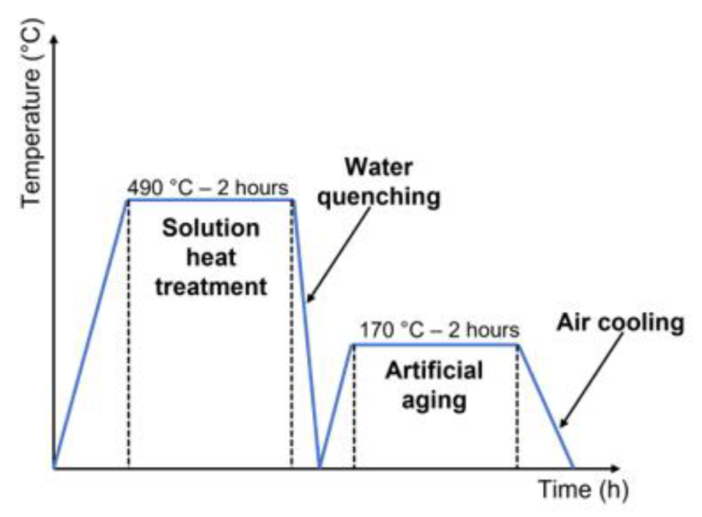
2. Materials and Methods

In the current work, two primary aluminum alloys, AlSi10MnMg and AlMg4Fe2, and two secondary aluminum alloys, AlSi12(Fe) and AlSi10Mg(Fe) were studied. The chemical composition of the castings was performed on Ametek SPECTROMAXx equipment (SPECTRO, Kleve, Germany) using arc/spark optical emission spectrometry (OES). The results are shown in Table 1.
The component analyzed was a power electronics casing (Figure 1). It was produced with a 400-ton Colosio (Colosio, Botticino Sera, Italy) cold chamber HPDC machine connected to a Fondarex (Fondarex, Switzerland) vacuum system. The parts were injected under a vacuum pressure of 200 mbar and also under atmospheric pressure to study the influence of vacuum application on the porosity of the parts. The pouring temperature of the AlSi12(Fe), AlSi10Mg(Fe), and AlSi10MnMg alloys was 670 °C, and for the AlMg4Fe2 alloy, it was 700 °C. The die temperature was measured with a thermal imaging camera and varied between 145 and 220 °C.
Twelve specimens were machined from the casted parts for each alloy and condition. However, due to the warping of some parts during mold ejection, it was necessary to straighten these parts to obtain specimens with the same thickness along the section. The tensile tests were performed at room temperature on an Instron 5900R (Instron, Norwood, MA, USA) with a 5 kN load cell, at a constant crosshead speed of 0.5 mm/min. For each alloy and condition, there 9 specimens were tested in the as-cast state and 12 specimens after heat treatment.
The microstructural analysis was carried out using an Olympus PMG 3 optical microscope (Olympus, Tokyo, Japan) with a Leica DP12 digital camera (Leica, Wetzlar, Germany). Due to the typical microstructural refinement of the injected alloys, there was some difficulty in identifying typical structures in the images observed with the optical microscope. Thus, for a better characterization of the microstructure, a FEI Quanta 400FEG ESEM high-resolution scanning electron microscope (SEM) (FEI Company, Hillsboro, OR, USA) was used in conjugation with an EDAX Genesis X4M instrument for energy-dispersive X-ray spectroscopy microanalysis (EDS) (Oxford Instruments, Oxfordshire, UK).
The hardness measurements were performed in an EMCO M4U-075 hardness tester (EMCO-Test, Kuchl, Austria). Taking into account the hardness values that were expected, a Brinell test (HB5) was performed with a spherical tip indentor in tungsten carbide with a diameter of 2.5 mm, which corresponds to a force of 31.25 kgf.
The T6 heat treatment (Figure 2) was performed in an M. J. Amaral forced convection furnace (M.J.Amaral—Equipamentos Industriais Lda, Vale de Cambra, Portugal) with a chamber of dimensions 600 × 600 × 700 mm³. The furnace chamber has three thermocouples along its height to evaluate the temperature distribution, and three test parts instrumented with thermocouples were used to monitor the temperature throughout the heat treatment.
The analysis of the part defects was performed by 3D X-ray computed tomography (CT) on a Nikon XT H 225 ST 2X instrument (Nikon, Tokyo, Japan). This analysis was conducted on parts of all alloys under study before heat treatment and for parts of AlSi10Mg(Fe) and AlSi10MnMg alloys after T6 heat treatment.

3. Results and Discussion

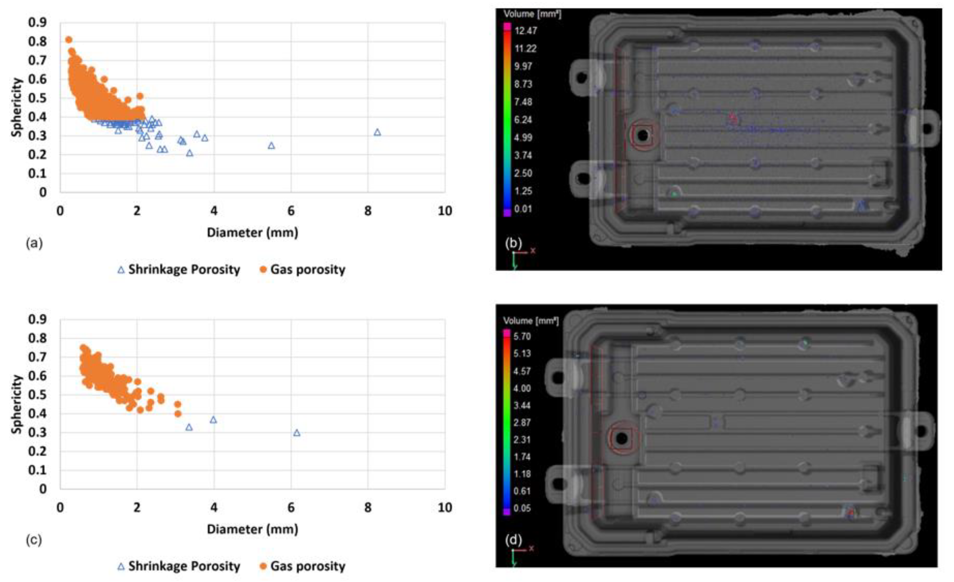
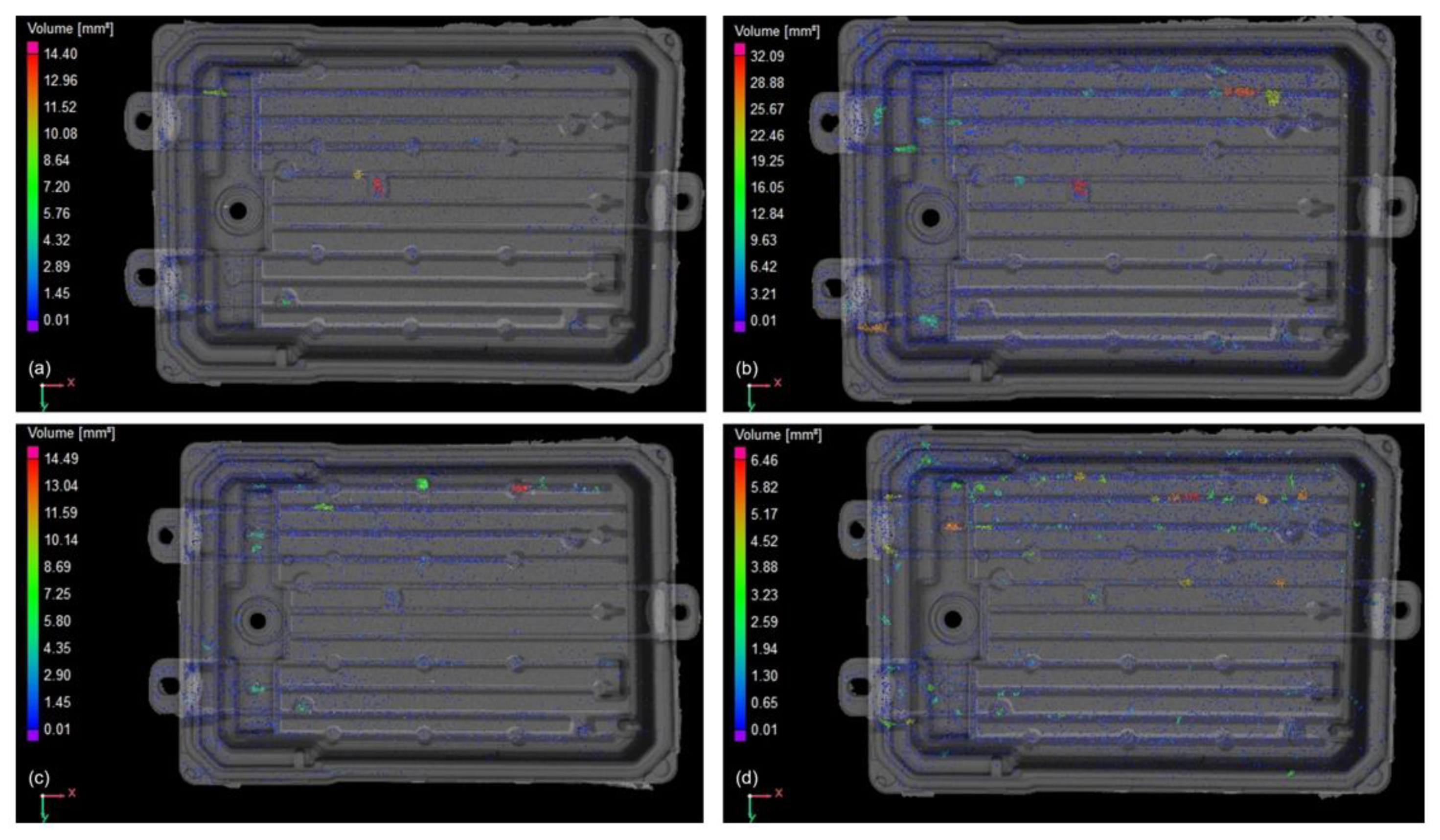
3.1. Three-Dimensional X-ray Computed Tomography

Components made of the four alloys under study (AlSi12(Fe), AlSi10Mg(Fe), AlSi10MnMg, and AlMg4Fe2) were analyzed using computed tomography. Using this technology, it was possible to analyze the quantity of defects, defect volume (mm³), defect volume ratio (%), sphericity, defect diameter (mm), and average defect volume (mm³). These results for the parts in the as-cast state are presented in Table 2.
VADC led to a reduction in porosity in all the alloys:
  • 64% reduction in AlSi12(Fe) alloy;
  • 81% reduction in AlSi10Mg(Fe) alloy;
  • 60% reduction in AlSi10MnMg alloy;
  • 78% reduction in AlMg4Fe2 alloy.
Considering that the injection conditions and parameters were more stable and optimized for the AlSi10MnMg alloy, it is expected that for a vacuum level of 200 mbar, the defect reduction is around 60%.
The shrinkage porosities usually appear in the areas of the part with greater massiveness (higher thickness). In this part, the shrinkage porosities generally occur in the areas of the ejector pins (circular areas of the part), which are zones of higher thickness when compared with the remaining part (Figure 3b,d).
By analyzing the graphs in Figure 3, it can be seen that the reduction in the quantity of defects is mainly due to a reduction in the number of gas porosities. The difference between shrinkage and gas porosity was based on the work of Kang et al. [20]. The distinction was made taking into account the sphericity of the defect, i.e., defects with sphericity ≥0.4 were considered gas porosities. From the analysis of the graphs, it is also possible to conclude that there is a large number of shrinkage porosities with sphericity very close to 0.4, which can be a combination of shrinkage porosity and gas porosity. In addition, it is possible to conclude that the smaller the defect diameter, the higher its sphericity.
After performing T6 heat treatment, the same parts of AlSi10Mg(Fe) and AlSi10MnMg alloys were analyzed using computed tomography to understand the influence that the solution heat treatment would have on the porosities. The results are presented in Table 3.
After the T6 heat treatment, the number of defects increased exponentially in the parts injected with vacuum assistance. This can be explained by the fact that the CT analysis only detected defects of volume ≥ 0.01 mm³. In the parts injected with vacuum assistance in the as-cast state, there could be defects at lower volumes than mentioned that were not visualized, but that during solution heat treatment increased their volume and started to be detected in the analysis that was performed after the heat treatment. In addition, it was observed that the average defect volume, in the vacuum-assisted injected parts, decreased by 56% and 70% for AlSi10Mg(Fe) and AlSi10MnMg alloys, respectively, due to the appearance of a large number of small-volume defects.
For AlSi10Mg(Fe) alloy parts injected with vacuum assistance, the defect volume ratio was reduced by 25% when compared to that obtained for conventional injected parts. Contrary to what was observed in the as-cast state for the AlSi10MnMg alloy, after heat treatment, VADC led to an increase in the percentage of defects by approximately 75%. Analyzing the values in Table 3 and observing Figure 4, it is possible to conclude that the AlSi10MnMg alloy parts injected with vacuum assistance have a greater quantity of larger volume defects. As the defect volume ratio calculation considers the defect volume and the part volume (this being constant for all parts analyzed), an increase in the number of defects with larger diameters leads to an increase in the defect volume, which in turn implies an increase in the defect volume ratio value.
To better understand the influence of the heat treatment on part porosities, an analysis of the defects before and after the heat treatment was performed, as shown in Figure 5.
By analyzing the graphs in Figure 5, it can be concluded that the number and diameter of the gas porosities increase after the T6 heat treatment. It was also found that the number of shrinkage porosities increased. This increase may be due to the joining of gas porosities (coalescence phenomenon) which causes the distortion of their shape leading to a decrease in sphericity. Thus, these gas porosities that are joined together could be considered shrinkage porosities.

3.2. Mechanical Properties

The mechanical properties of all the alloys in the as-cast state under study were analyzed. The results can be seen in Table 4.
Except for the AlSi12(Fe) alloy in HPDC, a yield strength in accordance with the standard value was obtained for all the alloys. Regarding ultimate tensile strength and elongation, the standard values were not reached with the exception of the elongation for the secondary alloys. The fact that the tested specimens did not have as their surface the part’s skin, which is an area that due to the high cooling speed leads to a refined microstructure that promotes an improvement in the mechanical properties, may explain why the mechanical properties obtained are far from the standard values. In addition, there was a variation in the cross-sectional area of the specimens, which may influence the dilution of defects. This dilution can affect the cross-sectional area value, and therefore lead to changes in the mechanical properties.
From the analysis of Table 4, it can be observed that the use of a vacuum in the injection did not bring significant improvements to the mechanical properties. In the literature, for a vacuum level similar to the level applied (170 mbar), the use of vacuum led to a slight improvement in mechanical properties, but this was not significant [17]. Thus, the results obtained are more or less in line with what was expected; however, VADC specimens should have higher results than HPDC ones.
The primary alloys showed better elongation than the secondary alloys. The low percentages of iron in the AlSi10MnMg alloy and the low percentage of silicon in the AlMg4Fe2 alloy are key features for reducing the needles of the β-Al5FeSi phase detrimental to ductility.
The alloy with the highest ductility is AlMg4Fe2, but the values obtained are about 60–70% lower than the values that were expected. This difference can be explained by the fact that it was the first time that this alloy was injected in the foundry where these castings were performed and the parameters and injection conditions were not yet optimized. It should be noted that although this alloy presents the best mechanical properties without the need for T6 heat treatment, it is the only one that brings greater challenges related to its injection.
After the heat treatment, the mechanical properties obtained were those shown in Table 5.
After the heat treatment, the ductility of AlSi10Mg(Fe) alloy increased by 119% in vacuum-assisted die casting and by 25% in conventional die casting. Regarding the AlS10MnMg alloy, its ductility increased by 21% in vacuum-assisted die casting and increased by 50% in conventional die casting. This increase in ductility was due to the spheroidization of silicon during the solution heat treatment.
The yield and ultimate tensile strength of AlSi10Mg(Fe) alloy decreased after the heat treatment due to the softening of the material and insufficient duration of the artificial aging heat treatment for structural hardening. On the other hand, in the AlSi10MnMg alloy, there was an increase in yield and ultimate tensile strength. This was due to the precipitation of Mg-Si intermetallics in the aluminum matrix, as can be seen in Chapter 3.3. However, the mechanical properties of this alloy were superior in the conventional die casting, as three of the four parts injected with vacuum assistance that were used to produce tensile specimens had a higher quantity of defects (Table 3). This higher amount of defects leads to a reduction in the cross-sectional area of the specimens which impairs the value of the mechanical properties.
The hardness measurements before and after the T6 heat treatment are shown in Table 6.
The softening of the AlSi10Mg(Fe) alloy can be proven by the drop in hardness that existed after the heat treatment. The drop in hardness was approximately 31%. This softening of the material may have been caused by the coarsening of the silicon during solution heat treatment and/or insufficient stage time during artificial aging that did not allow the peak hardness to be reached.
In the case of the AlSi10MnMg alloy, an average hardness value of 85 HB was obtained, slightly below the minimum expected, 90 HB. If the artificial aging heat treatment was carried out for more than two hours, presumably, the standardized hardness value (peak hardness) would be reached. The hardness increased due to the precipitation of Mg-Si intermetallics in the aluminum matrix.

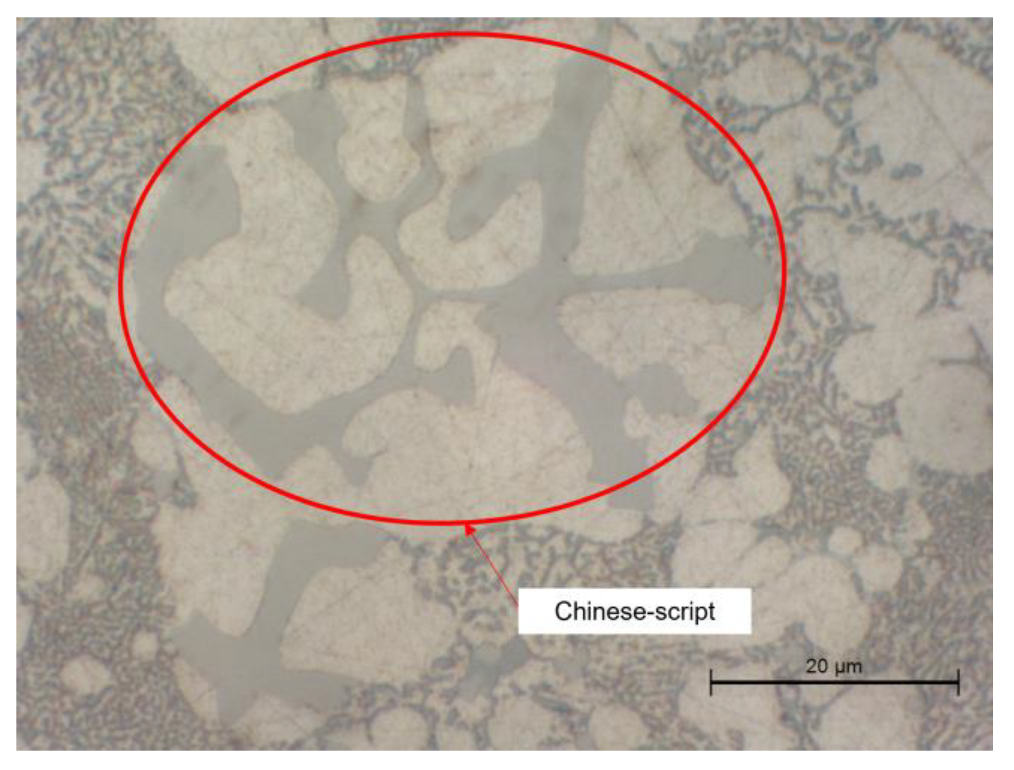
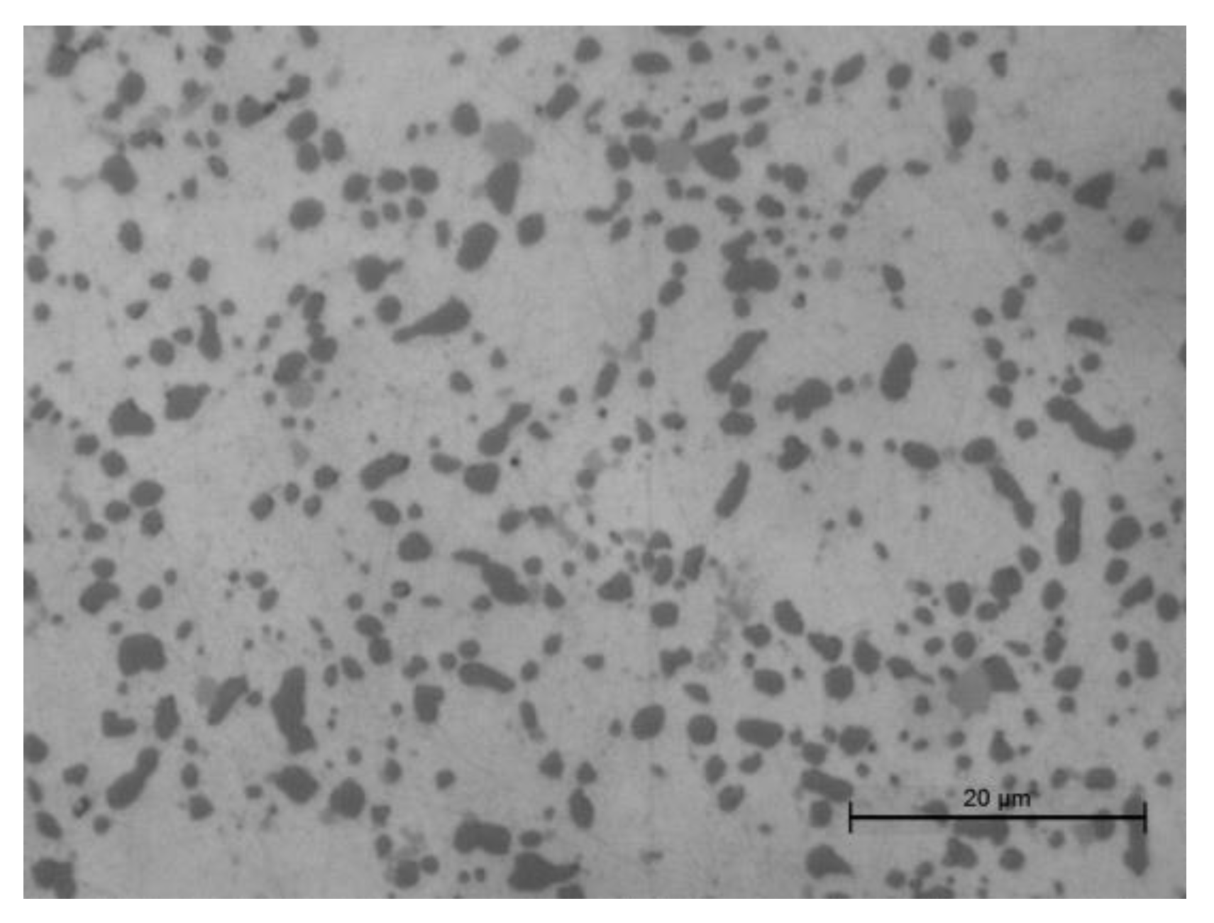
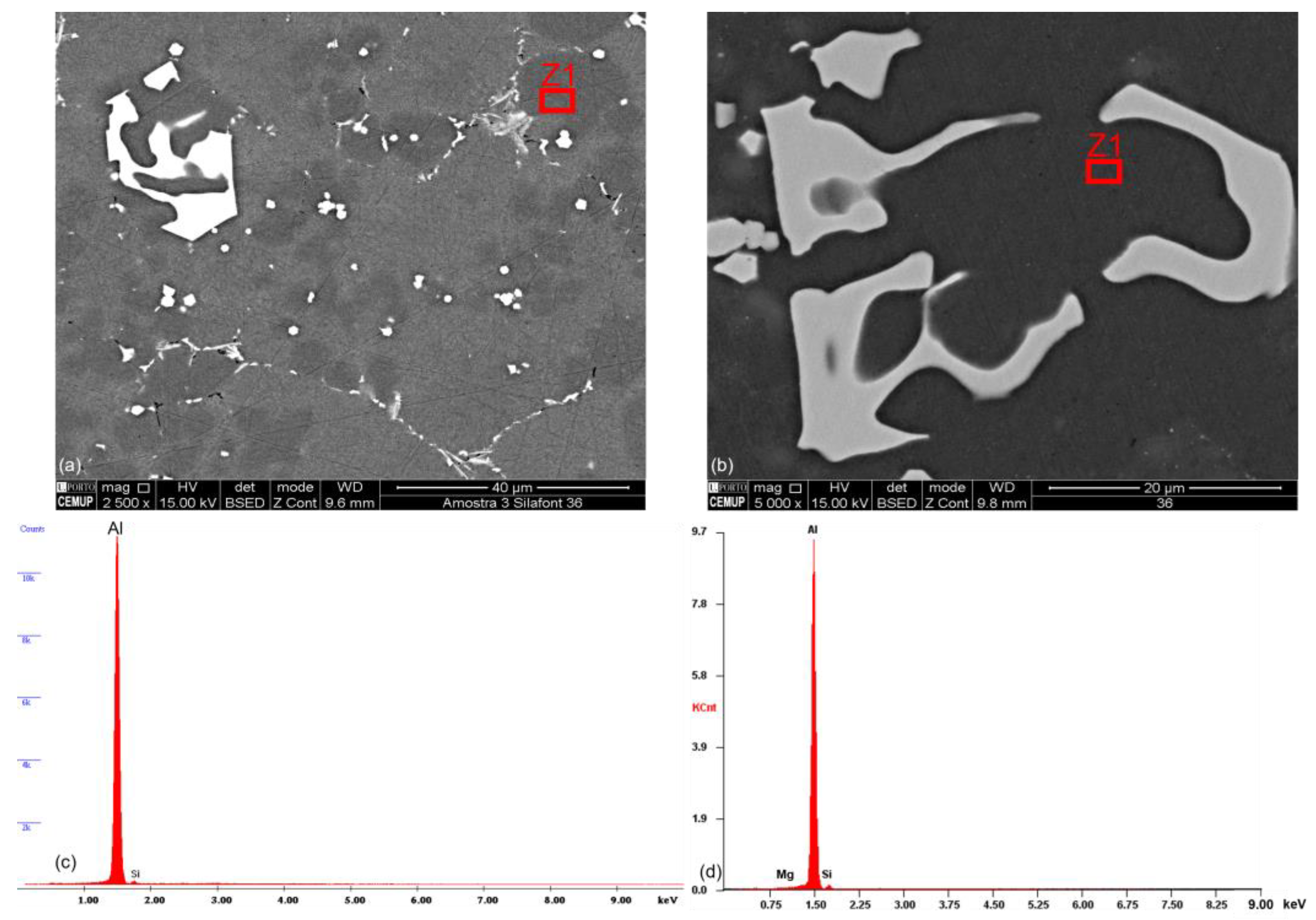
3.3. Microstructures

Due to the high cooling rates typical of the HPDC process, there is a refinement of the microstructure that makes it difficult to identify typical phases of these alloys by optical microscopy. To facilitate this analysis, SEM-EDS was used. In Figure 6, the backscattered SEM images of AlSi10Mg(Fe) and AlSi10MnMg alloys are presented. In this mode, the higher the atomic number of the element, the brighter it will be in the image. Comparing both images of Figure 6, knowing that iron has a higher atomic number than silicon, magnesium, aluminum, and manganese and that the β-Al5FeSi phase has a morphology that resembles a needle, it is possible to conclude that AlSi10Mg(Fe) secondary alloy (Figure 6a) has a higher amount of needles (detrimental to ductility) than the primary AlSi10MnMg alloy (Figure 6b).
In the AlSi10MnMg alloy, due to a reduction in the iron percentage and an increase in the manganese percentage, phases with a Chinese-like morphology (Figure 7) appear that are less detrimental than the β-Al5FeSi phases with needle-like morphology.
After the T6 heat treatment due to solution heat treatment, silicon fragmentation and spheroidization occurred in both alloys (AlSi10Mg(Fe) and AlSi10MnMg). Figure 8 shows the microstructure of AlSi10MnMg alloy after heat treatment.
With the SEM-EDS analysis, it was possible to verify that there was precipitation of Mg-Si intermetallics in the aluminum matrix during the artificial aging because Mg is detected in the Z1 zones (αAl phase) of Figure 9d when without heat treatment it was not detected, as shown in Figure 9c.

4. Conclusions

In this work, the influence that vacuum has on the reduction in porosities and improvement of mechanical properties, the influence that T6 heat treatment has on the microstructure, mechanical properties, hardness, and porosities, and, finally, the major differences between the mechanical properties of primary and secondary alloys were investigated. The main conclusions to be drawn from this study are:
  • In the as-cast state, VADC led to a reduction in the quantity and percentage of defects. As the injection parameters and conditions were optimized for the AlSi10MnMg, it is expected that for a vacuum level of 200 mbar, the reduction in defects is around 60%.
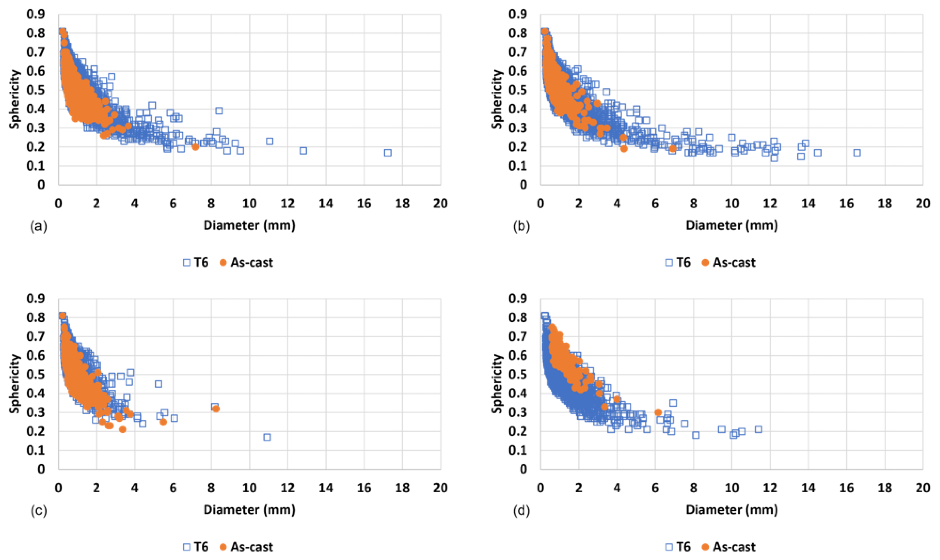
  • After the heat treatment, the quantity of gas and shrinkage porosities increased. Small volume defects that were not detected in the as-cast state analysis increased their volume during the solution heat treatment and were detected after the T6 heat treatment. Due to the coalescence phenomenon, there was a distortion of the shape of the gas porosities that led to a decrease in their sphericity and were considered shrinkage porosities.
  • Considering the results presented in the literature for vacuum levels close to the one used in this experimental work, a big improvement in the mechanical properties of parts injected with vacuum assistance was not expected. In this work, due to problems related to vacuum generation during the injection, it was not possible to obtain better mechanical properties in the vacuum-injected parts, even if these were small improvements.
  • The primary alloys (AlSi10MnMg and AlMg4Fe2) showed better ductility than the secondary alloys (AlSi12(Fe) and AlSi10Mg(Fe)). This was expected due to the needle-like β phase present in larger quantities in secondary alloys. This phase is detrimental to ductility since crack initiation is likely to occur in these needles.
  • In the as-cast state, the AlMg4Fe2 alloy presented the highest elongation values. However, the values obtained were 60–70% lower than the standard ones. The worst castability of this alloy and the poor improvement of the injection parameters may explain the values obtained.
  • After the T6 heat treatment, the elongation of AlSi10Mg(Fe) alloy increased by 119% in the vacuum-assisted injected parts and 25% in the conventionally injected parts. Furthermore, the elongation of AlSi10MnMg alloy increased by 21% in the vacuum-assisted injected parts and 50% in the conventionally injected parts. This increase in ductility is justified by the spheroidization of silicon. The YS and UTS of AlSi10Mg(Fe) alloy decreased after the heat treatment as a result of the softening of the material during the solution heat treatment and the insufficient duration of the artificial aging cycle. The YS and UTS of AlSi10MnMg alloy increased after the heat treatment; however, the mechanical properties of the conventionally injected parts were higher than the vacuum-assisted injected parts because the latter had a higher percentage of defects than the conventionally injected parts. This higher quantity of defects leads to a reduction in the specimen’s cross-sectional area and results in lower mechanical properties.

Author Contributions

Conceptualization, G.S.; methodology, G.S. and R.M.; software, G.S. and R.M.; validation, G.S., R.N., R.M., R.S., J.S., R.P.S. and L.A.; investigation, G.S., R.N., R.M., R.S., J.S., R.P.S. and L.A.; writing—original draft preparation, G.S.; writing—review and editing, G.S., R.N., R.M., R.S., J.S., R.P.S. and L.A.; supervision, R.N.; project administration, R.N. All authors have read and agreed to the published version of the manuscript.

Funding

Authors gratefully acknowledge the funding of Project Hi-rEV—Recuperação do Setor de Componentes Automóveis (C644864375-00000002), co-financed by Plano de Recuperação e Resiliência (PRR), through NextGeneration EU.

Data Availability Statement

Not applicable.

Acknowledgments

The authors would like to acknowledge the Project POCI-01-0247-FEDER-039920—SMARTINJECT: DESENVOLVIMENTO DE PEÇAS DE ELEVADO DESEMPENHO INJETADAS EM LIGAS DE ALUMÍNIO, co-financed by Programa Operacional Competitividade e Internacionalização (COMPETE 2020), through Fundo Europeu de Desenvolvimento Regional (FEDER).

Conflicts of Interest

The authors declare no conflict of interest.

References

  1. Czerwinski, F. Current Trends in Automotive Lightweighting Strategies and Materials. Materials 2021, 14, 6631. [Google Scholar] [CrossRef] [PubMed]
  2. Aluminium in Cars—Unlocking the Light-Weighting Potential; European Aluminium Association: Woluwe-Saint-Pierre, Belgium, 2013; Available online: https://www.european-aluminium.eu/media/3371/aluminium-in-cars-unlocking-the-lightweighting-potential.pdf (accessed on 13 September 2022).
  3. Svendsen, A. Aluminum Continues Unprecedented Growth in Automotive Applications. Light Metal Age. Available online: www.lightmetalage.com (accessed on 9 March 2022).
  4. Luo, A.A.; Sachdev, A.K.; Apelian, D. Alloy development and process innovations for light metals casting. J. Mater. Process. Technol. 2022, 306, 117606. [Google Scholar] [CrossRef]
  5. Hartlieb, M. Aluminum alloys for structural die casting. Die Cast. Eng. 2013, 57, 40–43. [Google Scholar]
  6. Casarotto, F.; Franke, A.J.; Franke, R. High-pressure die-cast (HPDC) aluminium alloys for automotive applications. In Advanced Materials in Automotive Engineering; Rowe, J., Ed.; Elsevier: Amsterdam, The Netherlands, 2012; pp. 109–149. [Google Scholar]
  7. Cinkilic, E.; Ridgeway, C.D.; Yan, X.; Luo, A.A. A formation map of iron-containing intermetallic phases in recycled cast aluminum alloys. Metall. Mater. Trans. A 2019, 50, 5945–5956. [Google Scholar] [CrossRef]
  8. Nath, J. Aluminum Castings Engineering Guide; ASM International: Materials Park, OH, USA, 2018. [Google Scholar]
  9. Campbell, J. Perspective Chapter: A Personal Overview of Casting Processes. In Casting Processes and Modelling of Metallic Materials; Abdallah, Z., Ed.; IntechOpen: London, UK, 2021; pp. 1–17. [Google Scholar]
  10. Jolly, M. Die-Casting (High-Pressure Die-Casting). In Comprehensive Structural Integrity; Milne, I., Ritchie, R.O., Karihaloo, B., Eds.; Elsevier: Amsterdam, The Netherlands, 2003; Volume 1, pp. 413–415. [Google Scholar]
  11. Anderson, K.; Weritz, J.; Kaufman, J.G. ASM Handbook, Volume 2A: Aluminum Science and Technology; ASM International: Materials Park, OH, USA, 2018. [Google Scholar]
  12. Kaufman, J.G.; Rooy, E.L. Aluminum Alloy Castings: Properties, Processes, and Applications; ASM International: Materials Park, OH, USA, 2004. [Google Scholar]
  13. Polmear, I.; StJohn, D.; Nie, J.-F.; Qian, M. High-pressure die casting. In Light Alloys—Metallurgy of the Light Metals, 5th ed.; Elsevier: Amsterdam, The Netherlands, 2017; pp. 134–139. [Google Scholar]
  14. Nourian-Avval, A.; Fatemi, A. Characterization and Analysis of Porosities in High Pressure Die Cast Aluminum by Using Metallography, X-Ray Radiography, and Micro-Computed Tomography. Materials 2020, 13, 3068. Available online: https://www.mdpi.com/1996-1944/13/14/3068 (accessed on 16 November 2022). [CrossRef] [PubMed]
  15. Hansen, F.; Ulbricht, M. Data from inline CT increase quality and efficiency. Cast. Plant Technol. Int. 2022, 3, 50–53. [Google Scholar]
  16. Committee, A.I.H. ASM Handbook, Volume 15: Casting; ASM International: Materials Park, OH, USA, 2008. [Google Scholar]
  17. Szalva, P.; Orbulov, I.N. The effect of vacuum on the mechanical properties of die cast aluminum AlSi9Cu3 (Fe) alloy. Int. J. Met. 2019, 13, 853–864. [Google Scholar] [CrossRef]
  18. Hu, C.; Zhao, H.; Wang, X.; Fu, J. Microstructure and properties of AlSi12Fe alloy high pressure die-castings under different vacuum levels. Vacuum 2020, 180, 109561. [Google Scholar] [CrossRef]
  19. Dong, X.; Zhu, X.; Ji, S. Effect of super vacuum assisted high pressure die casting on the repeatability of mechanical properties of Al-Si-Mg-Mn die-cast alloys. J. Mater. Process. Technol. 2018, 266, 105–113. [Google Scholar] [CrossRef]
  20. Kang, H.-J.; Jang, H.-S.; Oh, S.-H.; Yoon, P.-H.; Lee, G.-H.; Park, J.-Y.; Kim, E.-S.; Choi, Y.-S. Effects of solution treatment temperature and time on the porosities and mechanical properties of vacuum die-casted and T6 heat-treated Al–Si–Mg alloy. Vacuum 2021, 193, 110536. [Google Scholar] [CrossRef]
  21. Alloys, R. Primary Aluminium Alloys for Pressure Die Casting. Rheinfelden Alloys. Available online: https://rheinfelden-alloys.eu/wp-content/uploads/2016/01/05-HB-DG_Ci_Sf_Cm_Td_Ma_RHEINFELDEN-ALLOYS_2015_EN.pdf (accessed on 7 November 2022).
  22. Alumínio e ligas de alumínio, NP EN1706. 2000. Available online: https://biblioteca.isel.pt/cgi-bin/koha/opac-detail.pl?biblionumber=19990 (accessed on 7 November 2022).
  23. Alloys, R. Primary Aluminum HPDC Alloys for Structural Casts in Vehicle Construction. Rheinfelden Alloys. Available online: https://pdfslide.tips/documents/primary-aluminum-hpdc-alloys-for-structural-casts-in-rheinfelden-innovative.html?page=1 (accessed on 7 November 2022).
Figure 1. (a) Power electronics casing showing the position of the tensile specimens; (b) Specimen’s dimensions (in mm).
Metals 13 00389 g001
Figure 2. T6 heat treatment performed.
Metals 13 00389 g002
Figure 3. Analysis of defects in the as-cast state. (a) Sphericity and diameter of the porosities present in the AlSi10MnMg alloy No. 1 part (HPDC); (b) Results of CT analysis of AlSi10MnMg alloy No. 1 part (HPDC); (c) Sphericity and diameter of the porosities present in the AlSi10MnMg alloy No.3 part (VADC); (d) Results of CT analysis of AlSi10MnMg alloy No. 3 part (VADC).
Metals 13 00389 g003
Figure 4. Analysis of defects in the heat-treated parts of AlSi10MnMg alloy. (a) Part No. 1 injected by HPDC; (b) Part No. 1 injected by VADC; (c) Part No. 2 injected by HPDC; (d) Part No. 2 injected by VADC.
Metals 13 00389 g004
Figure 5. Comparison of porosity in the part in the as-cast state and after being heat-treated. (a) AlSi10Mg(Fe) part No. 3 conventionally injected; (b) AlSi10Mg(Fe) part No. 2 injected with vacuum assistance; (c) AlSi10MnMg part No. 1 conventionally injected; (d) AlSi10MnMg part No. 3 injected with vacuum assistance.
Metals 13 00389 g005
Figure 6. The as-cast SEM microstructure. (a) AlSi10Mg(Fe) alloy; (b) AlSi10MnMg alloy.
Metals 13 00389 g006
Figure 7. Chinese script in AlSi10MnMg alloy.
Metals 13 00389 g007
Figure 8. Silicon fragmentation and spheroidization in AlSi10MnMg alloy.
Metals 13 00389 g008
Figure 9. Precipitation of Mg-Si intermetallics in the aluminum matrix in AlSi10MnMg alloy. (a) Z1-αAl phase before heat treatment; (b) Z1-αAl phase after heat treatment; (c) Spectra of EDS analysis in Z1 zone before heat treatment; (d) Spectra of EDS analysis in Z1 zone after heat treatment.
Metals 13 00389 g009
Table 1. Chemical composition of the alloys under study (wt %).
AlloySiFeMgMnCuZnTiSrAl
AlSi12(Fe)12.10.81-0.400.250.100.03-86.22
AlSi10Mg(Fe)10.60.880.20.090.140.050.04-87.97
AlSi10MnMg11.10.130.250.600.0010.0010.040.01087.82
AlMg4Fe20.101.504.900.010.010.010.01-93.38
Table 2. Results of porosity measurement in as-cast parts by 3D X-ray computed tomography.
AlloyVacuumPart No.Number of DefectsDefects Volume (mm³)Average Defect Volume (mm³)Defect Volume Ratio (%)
AlSi12(Fe)Yes17817.330.2220.010
No121752.290.2410.030
AlSi10Mg(Fe)Yes17919.190.2420.013
2206285.280.0420.061
325354.530.2160.039
No111,525199.550.0180.143
215,528366.480.0250.262
315,921259.890.0170.186
AlSi10MnMgYes135776.010.2130.055
226457.980.2200.042
327962.860.2260.046
No1379298.030.0270.071
26782161.490.0250.116
37138233.910.0340.169
AlMg4Fe2Yes119688.750.4530.070
No11115399.340.3580.290
Table 3. Results of porosity measurement in heat-treated parts by 3D X-ray computed tomography.
AlloyVacuumPart No.QuantitiesDefects Volume (mm³)Average Defect Volume (mm³)Defect Volume Ratio (%)
AlSi10Mg(Fe)Yes124,1921233.330.0520.869
226,7342305.230.0871.618
322,9991877.710.0821.329
No125,9561631.460.0631.147
243,6903779.000.0872.646
327,6191835.980.0671.298
AlSi10MnMgYes126,5981701.990.0641.215
226,1381575.400.0611.127
318,3381302.170.0710.935
No112,450507.470.0410.361
217,230856.980.0500.613
318,1121250.510.0690.897
Table 4. Mechanical properties of the alloys under study in the as-cast state [21,22,23].
AlloyYield Strength
(MPa)
Ultimate Tensile Strength (MPa)Elongation
(%)
Section Area (mm²)
VADCHPDCStandardVADCHPDCStandardVADCHPDCStandardVADCHPDC
AlSi12(Fe)137128>130190221>2401.021.93>111.83511.421
AlSi10Mg(Fe)143147>140215233>2401.341.54>112.19411.537
AlSi10MnMg138136120–150235234250–2902.663.015–1111.86011.701
AlMg4Fe2124126120–150180203240–2803.234.1510–2211.36911.530
Table 5. Mechanical properties of AlSi10Mg(Fe) and AlSi10MnMg alloys before and after heat treatment.
AlloyStateYield Strength (MPa)Ultimate Tensile Strength (MPa)Elongation (%)
AlSi10Mg(Fe)As-cast VADC1432151.34
As-cast HPDC1472331.54
T6 VADC1341882.94
T6 HPDC1321731.93
AlSi10MnMgAs-cast VADC1382352.66
As-cast HPDC1362343.01
T6 VADC1932393.23
T6 HPDC1962494.50
Table 6. Hardness values before and after T6 heat treatment.
Hardness (HB5)
AlloyAs-Cast StateHeat Treated
AverageStandardAverageStandard
AlSi12(Fe)83 ± 1.25Min. 60N.A.N.A.
AlSi10Mg(Fe)88 ± 1.62Min. 7061 ± 5.16-
AlSi10MnMg77 ± 2.5075–9585 ± 1.7890–110
AlMg4Fe269 ± 1.4165–75N.A.N.A.
Disclaimer/Publisher’s Note: The statements, opinions and data contained in all publications are solely those of the individual author(s) and contributor(s) and not of MDPI and/or the editor(s). MDPI and/or the editor(s) disclaim responsibility for any injury to people or property resulting from any ideas, methods, instructions or products referred to in the content.

