Article

Different Heat-Exposure Temperatures on the Microstructure and Properties of Dissimilar GH4169/IC10 Superalloy Vacuum Electron Beam Welded Joint

School of Materials Science and Engineering, Jiangxi University of Science and Technology, Ganzhou 341000, China
*
Authors to whom correspondence should be addressed.
Metals 2024, 14(3), 348; https://doi.org/10.3390/met14030348
Submission received: 8 February 2024 / Revised: 6 March 2024 / Accepted: 13 March 2024 / Published: 18 March 2024

Abstract

:
Vacuum electron-beam welding (EBW) was used to join the precipitation-strengthened GH4169 superalloy and a new nickel-based superalloy IC10 to fabricate the turbine blade discs. In this study, a solid solution (1050 °C/2 h for GH4169 and 1150 °C/2 h for IC10) and different heat-exposure temperatures (650 °C, 750 °C, 950 °C and 1050 °C/200 h, respectively) were used to study the high-temperature tensile properties and microstructure evolution of welded joints; meanwhile, the formation and evolution of the second phases of the joints were analyzed. After EBW, the welded joint exhibited a typical nail morphology, and the fusion zone (FZ) consisted of columnar and cellular structures. During the solidification process of the molten pool, Mo elements are enriched in the dendrites and inter-dendrites, and that of Nb and Ti elements was enriched in the dendrites, which lead to forming a non-uniform distribution of Laves eutectic and MC carbides in the FZ. The microhardness of the FZ gradually increased during thermal exposure at 650 °C and reached 300–320 HV, and the γ′ and γ″ phases were gradually precipitated with size of about 50 nm. Meanwhile, the microhardness of the FZ decreased to 260–280 HV at 750 °C, and the higher temperature resulted in the coarsening of the γ″ phase (with a final size of about 100 nm) and the formation of the acicular δ-phase. At 950 °C and 1050 °C, the microhardness of FZ decreased sharply, reaching up to 170~190 HV and 160~180 HV, respectively. Moreover, the Laves eutectic and MC carbides are dissolved to a greater extent without the formation of γ″ and δ phases; as a result, the absent of γ″ and δ phases are attributed to the significant improvement of segregation at higher temperatures.

1. Introduction

In recent years, developments in the aerospace industry have increased the demand for nickel-based superalloys, whose components are increasingly used in hot-end components such as modern gas turbines [1,2]. The IC10 Ni3Al-based alloy is one of the preferred materials for turbine blades as a new generation of superalloys, with excellently high strength and oxidation resistance over a wide range of high temperatures [3,4]. Although the IC10 alloy is sufficient to meet most of the service requirements, its high cost and complex preparation techniques limits its use. GH4169 (IN 718) is a precipitation-strengthened nickel-based superalloy, which is mainly used in aero-engines and is one of the candidates for low-pressure turbine discs due to its high strength and moderate creep resistance up to 650 °C [5]. Jointing the turbine blade IC10 alloy with the turbine disc GH4169 alloy to produce the integral leaf disc can not only save on cost but also combine the excellent properties of both alloys. Thus, it is believed that this research will be an interesting exploration.
The weldability, mechanical properties, and corrosion resistance of nickel-base superalloys are affected by the solidified structure of welded joints. Under the influence of welding’s heat input, the structure of the base-metal zone near the fusion zone (FZ) changes, forming the welding’s heat-affected zone (HAZ), which leads to the degradation of the mechanical properties [6]. Electron-beam welding (EBW) has the advantages of a small welding deformation and a narrow heat-affected zone, and is one of the basic joining processes of precipitation-strengthened nickel-based superalloys [7,8,9]. The segregation that occurs during the solidification of the melt pool may result in other phases appearing in the fusion zone. Aminzadeh Ahmad et al. [10] also pointed that high-energy beam welding (laser-beam welding, EBW) is capable of obtaining a narrow HAZ. The solidification of nickel-based high-temperature alloys containing the element Nb in the welding process occurs in three steps: the initial stage of L → γ, the subsequent stage of L → γ + NbC, and the final solidification stage of L → γ+Laves [11]. As a brittle phase, the nature of Laves relative to the molten zone is detrimental [12,13]. The regulation of the Laves phase is usually achieved by controlling the solidification conditions to inhibit Nb segregation to hinder the formation of the Laves phase, or by using high-temperature homogeneous heat treatments to dissolve the Laves phase [14,15]. However, the high-temperature homogeneous heat treatment inevitably has adverse effects on the base metal (grain coarsening, second-phase coarsening, and dissolution, etc.), so controlling the solidification conditions is an excellent means of controlling the Laves phase in the fusion zone. Low temperature gradients, high cooling rates, and high heat inputs can reduce Nb segregation, thereby reducing the volume fraction and size of the Laves phase [16], and such solidification conditions can be provided by EBW [17,18]. The application of EBW in the welding of the nickel-based superalloy has been widely studied. Kwon et al. [19] concluded that EBW produced a finer dendrite structure in the fusion zone of the IN 718 alloy with a smaller size and a lower content of Laves phases compared to TIG welding. Rem [20] also investigated that EBW is able to inhibit the segregation of Nb elements and the formation of Laves phase in the fusion zone of the IN 718 alloy. Wang et al. [21] pointed that the offset electron beam was able to reduce the precipitation of the Laves phase in the FZ. Thus, EBW is an excellent way to join IC10/GH4169 dissimilar superalloys, which can narrow the HAZ and inhibit the formation of primary harmful phases in the fusion zone.
Nickel-based superalloys have been exposed to high temperatures and complex stress environments for a long time, and the evolution of their microscopic morphology will significantly affect their service performance. For example, the γ″ phase, the main reinforcing phase in the GH4169 alloy, will be transformed into a harmful δ phase when used at a temperature above 650 °C for a long time, resulting in a decrease in the overall properties of the alloy [22]. Liu et al. [23] studied the microstructure and properties of the new wrought nickel-based superalloy under heat exposure at 650 °C, and found that after 2300 h of thermal exposure, there was no TCP phase and no γ′ region near the grain boundary, and the γ′ phase remained spherical (the critical size of the γ′ phase was 40–45 nm), and found that the tensile strength and yield strength of the alloy increased after heat exposure at 650 °C. He et al. [24] studied the microstructure of Hastelloy N superalloy-brazed joints after heat exposure, and found that M5B3 particles were introduced into the isothermal solidification zone (ISZ) of the joints after thermal exposure, resulting in a reduction in brazed-joint strength. Fan et al. [25] conducted a 750 °C heat-exposure experiment on the TIG-welded joints of the Nimonic 263 (N263) superalloy, and found that with the increase in heat exposure time, the γ′ phase in the fusion zone and base-metal area became coarser, and some γ′ phases were transformed into slat-like η phases, and the precipitation of grain boundaries’ η slats hindered crack propagation; these changes of the microstructure resulted in a decrease in the impact toughness of the joints. Liu et al. [26] investigated the changes in the microstructure and properties of the second-generation single-crystal superalloy DD6 under long-term aging, and showed that when aging at 980 °C for 1000 h, the alloy was absent in the second phase while the μ-phase precipitated while aging for 5000 h and 7500 h. At present, there are few studies on the structure and properties of nickel-based superalloy-welded joints under heat exposure, and it is of great significance to study and characterize the structural changes of welded joints to evaluate the performance of welded joints.
Precipitation-strengthened nickel-based superalloys have a high sensitivity to liquation cracking in the welding’s HAZ, which is related to the liquefaction of the components of the γ′/γ phase. Meanwhile, the microstructure stability and the evolution law of the second phase in the long-term high-temperature environment of the welded joints still need to be studied. In this study, vacuum EBW is used to weld IC10 and GH4169 dissimilar alloys, and the relationship between the heat-exposure temperature and the microstructure and properties of welded joints is clarified, with the formation and evolution of the second phase of the joints receiving further analysis, so as to provide a theoretical foundation for the study of the service performance of the integral leaf disc.

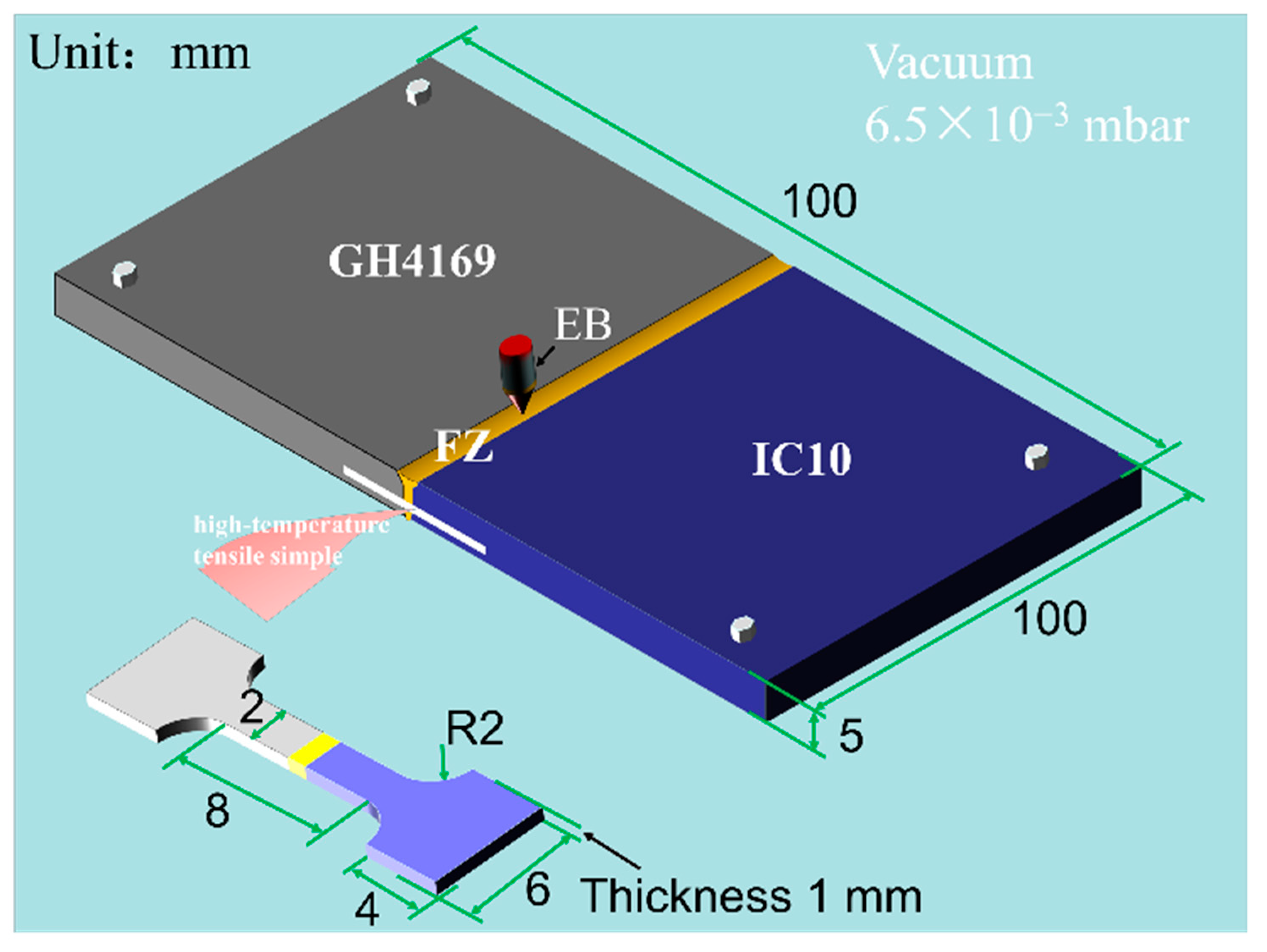
2. Materials and Methods

In this study, the commercial precipitation-strengthened nickel-based superalloy GH4169 and the Ni3Al-based alloy IC10 were used. The chemical compositions of the GH4169 and IC10 alloys are shown in Table 1. Two plate base materials (BMs) were processed into plates of 100 mm × 50 mm × 5 mm dimensions through wire electro-discharge machining.
The welding between IC10 BM and GH4169 BM was completed using a vacuum electron-beam welding (EBW) machine. The welding current was 25 mA, the welding voltage was 100 kV, and the welding rate was 10 mm/s, and the vacuum was set as 6.5 × 10⁻³ mbar. The overall morphology of the welded joint is shown in Figure 1, and it can be seen that the widths of the top and bottom surfaces of the welded joint are uniform. The width of the top surface of the welded joint is 3~4 mm, and no obvious defects such as macroscopic cracks and spatter are observed around the joint, indicating that the weld is well bonded. In order to design the changes in the structure and performance of welded joints in long-term-use environments, no-load heat-exposure experiments were set up for 200 h at temperatures of 650, 750, 950, and 1050 °C. After heat exposure, high-temperature tensile specimens were cut from the welded plate through wire-cut electrical discharge machining, and the geometric dimensions are shown in Figure 2. The high-temperature tensile tests were carried out at 700 °C, and the strain rate was 1 mm/min. The microhardness tests of the polished joint and joint section were carried out using a Vickers microhardness tester; the test force was 3 kgf, the holding time was 10 s, 10 points were selected as data points, and the average value was taken.
The microstructure characterizations were carried out using optical microscopy (OM, performed on Axio ScopeA1 Zeiss microscope, Zeiss, Oberkochen, Germany), scanning electron microscopy (SEM, performed on ZEISS ∑ IGMA equipment, Zeiss, Oberkochen, Germany), electron backscatter diffraction (EBSD) (Zeiss, Oberkochen, Germany), electron probe X-ray micro-analyzer (EPMA) and transmission electron microscopy (TEM). The specimens were mechanically ground, polished, and etched. The welded joints etched using a mixed solution of 6.5 g copper chloride + 60 mL concentrated hydrochloric acid + 40 mL anhydrous ethanol for 90 s was used for OM, SEM, and EPMA characterizations. After polishing, EBSD samples were prepared and electrolytically polished with a mixed solution of absolute ethanol/n-butanol/perchloric acid = 9:9:2 at an electrolytic voltage of 25 V and 0.5 A, with the sample as the anode and the copper plate as the negative electrode. For the preparation of TEM samples, the punched discs with diameter of 3 mm were polished to a certain extent and electrolytic double spraying was performed using a mixed solution of perchloric acid; the electrolyte formulation was nitric acid/methanol = 1:3 (vol.%), −30 °C, and had a DC voltage of 25 V. EBSD measurements were performed on the FEI Hlios Nanolab 600i Focused Ion Beam/SEM System with an accelerating voltage of 20 kV per sample and a scan step of 1.5 μm. Additionally, EBSD data were processed using Channel 5 analysis software (Oxford Instruments, Abingdon, UK), and the misorientation angle between 2–15° is defined as a low-angle grain boundary (LAGB), and that more than 15° is defined as a high-angle grain boundary (HAGB). Electron probe X-ray micro-analyzing (EPMA) was performed using JXA-iSP100 (JEOL, Tokyo, Japan). Transmission electron microscopy (TEM) observations were performed using a FEI Tecnai F20 (FEI Company Hillsboro, OR, USA) system operated at 200 kV.

3. Results and Discussions

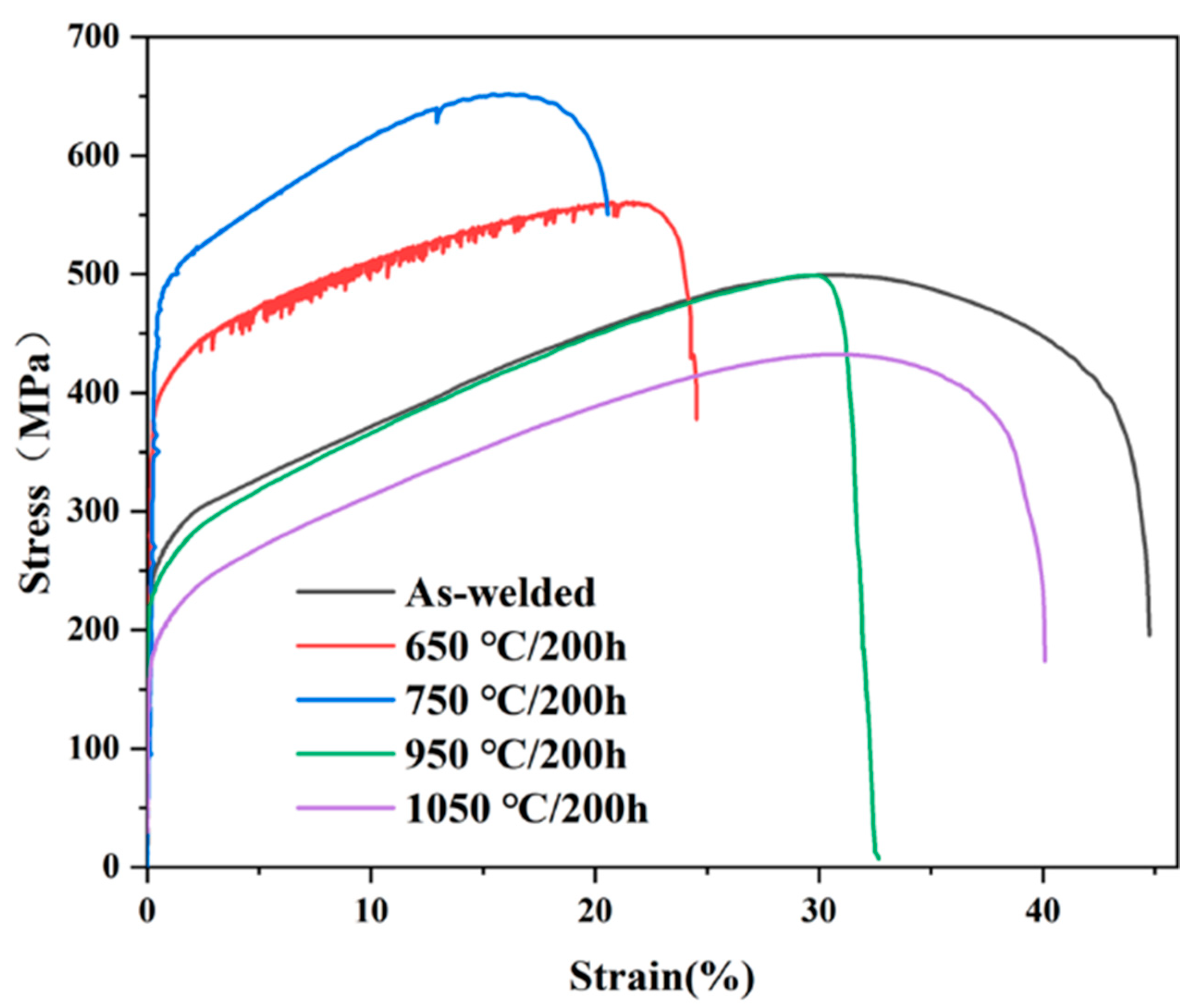
3.1. Mechanical Properties of the Welded Joints

Microhardness analysis can predict the strength of each region, which is an important parameter to reflect the performance of welded joints. The microhardness distribution curves of welded joints after different heat-exposure temperatures are shown in Figure 3. The microhardness of FZ is about 300~320 HV at 650 °C, 260~280 HV at 750 °C, 170~190 HV at 950 °C, and 160~180 HV at 1050 °C. It has the highest microhardness in the 650 °C heat-exposed FZ and BMs region, and the lowest microhardness in the 1050 °C heat-exposed FZ and BMs regions. As can be seen, the microhardness of FZ and both BMs showed a decreasing trend with the increase in heat-exposure temperature. The microhardness of the double BM’s side of the welded joint is comparable, and the FZ is higher than that of the BM side. The microhardness of the GH4169 region is higher than that of the IC10 region and FZ under heat exposure at 650 °C and 750 °C. The microhardness of FZ and both BMs tend to be consistent under the heat-exposure temperatures of 950 °C and 1050 °C. Moreover, the welded joints after different heat exposures were subjected to high-temperature tensile tests at 700 °C, and stress–strain curves such as in Figure 4. The high-temperature tensile strength of the as-welded, 650 °C and 750 °C heat-exposed welded samples, are 499.33, 560.75, and 652.06 MPa, respectively. Due to the competition between dynamic hardening and recrystallization softening during high-temperature tensile strengths, the stress–strain curve of the 650 °C heat-exposed welded joint exhibits a zigzag section. When the heat-exposure temperature is 950 °C and 1050 °C, the high-temperature tensile strengths are 499.83 and 433.9 MPa, respectively.

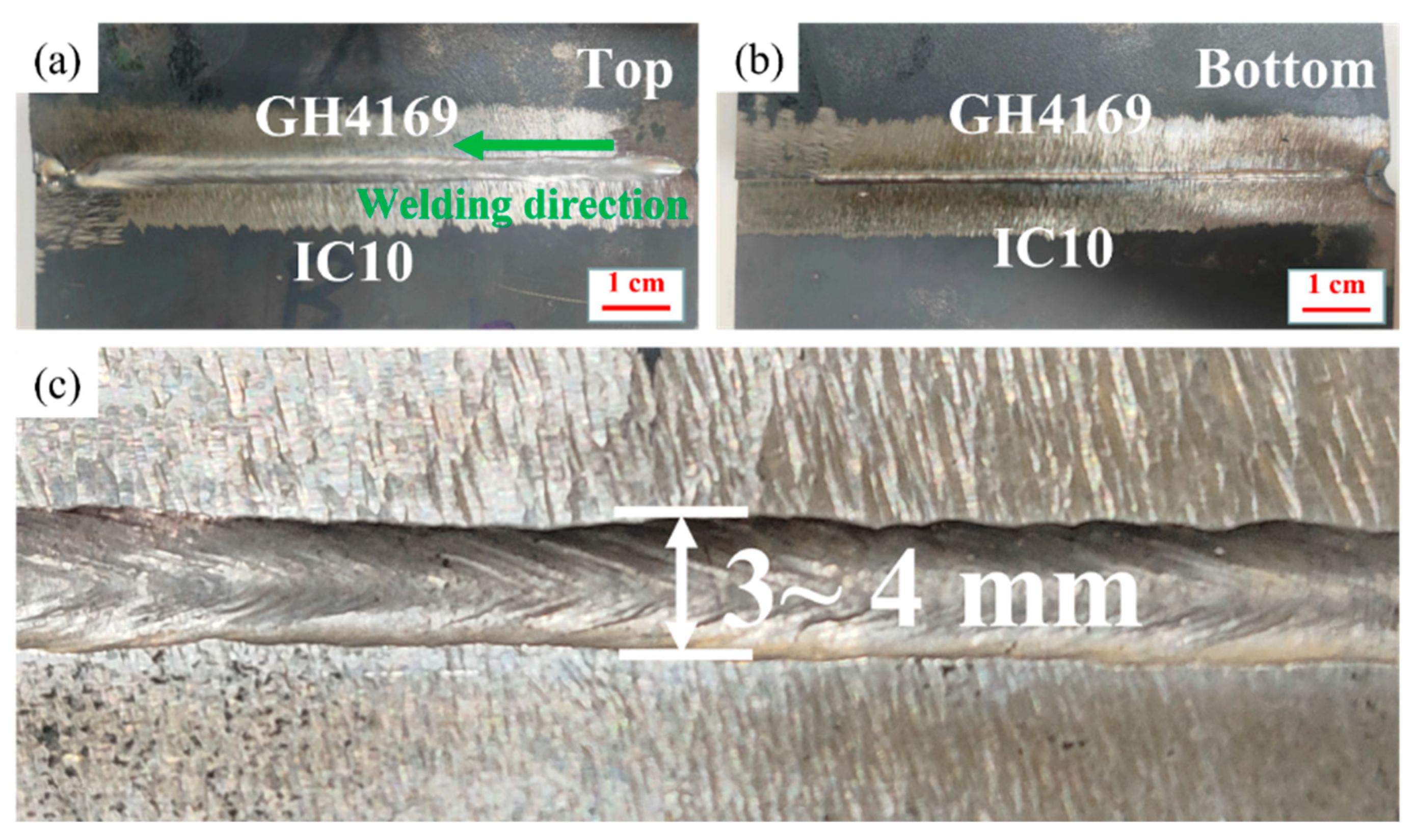
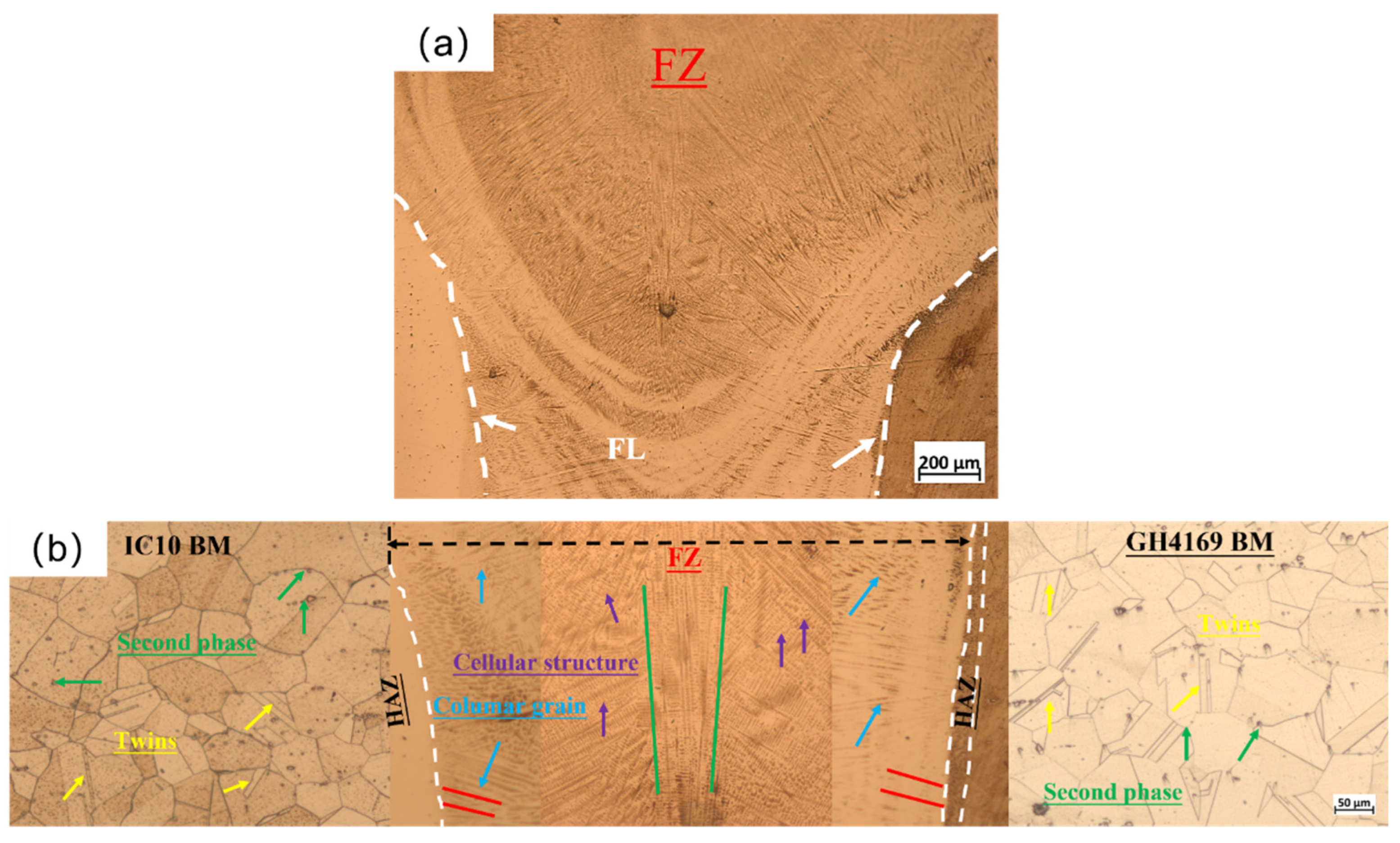
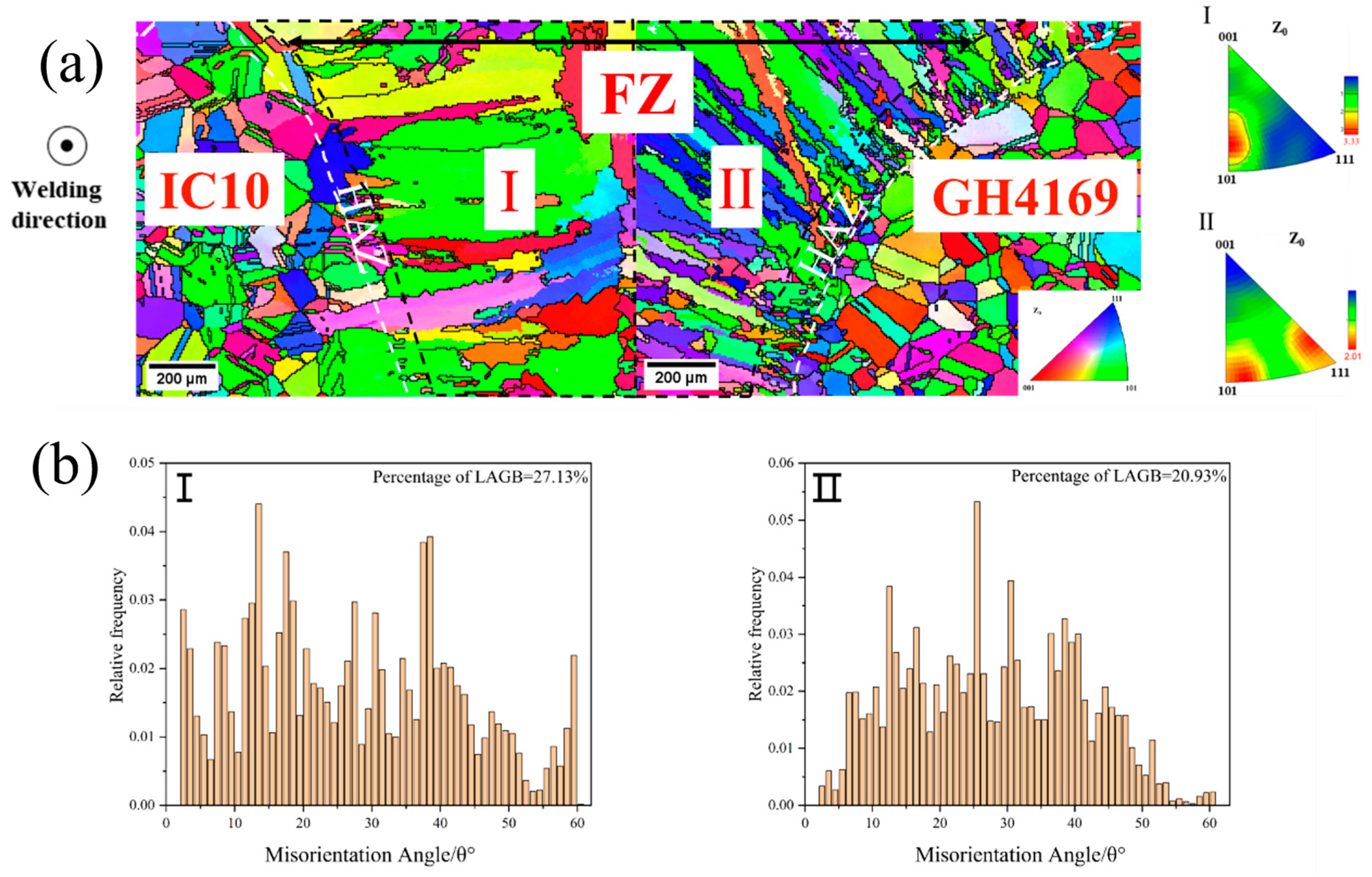
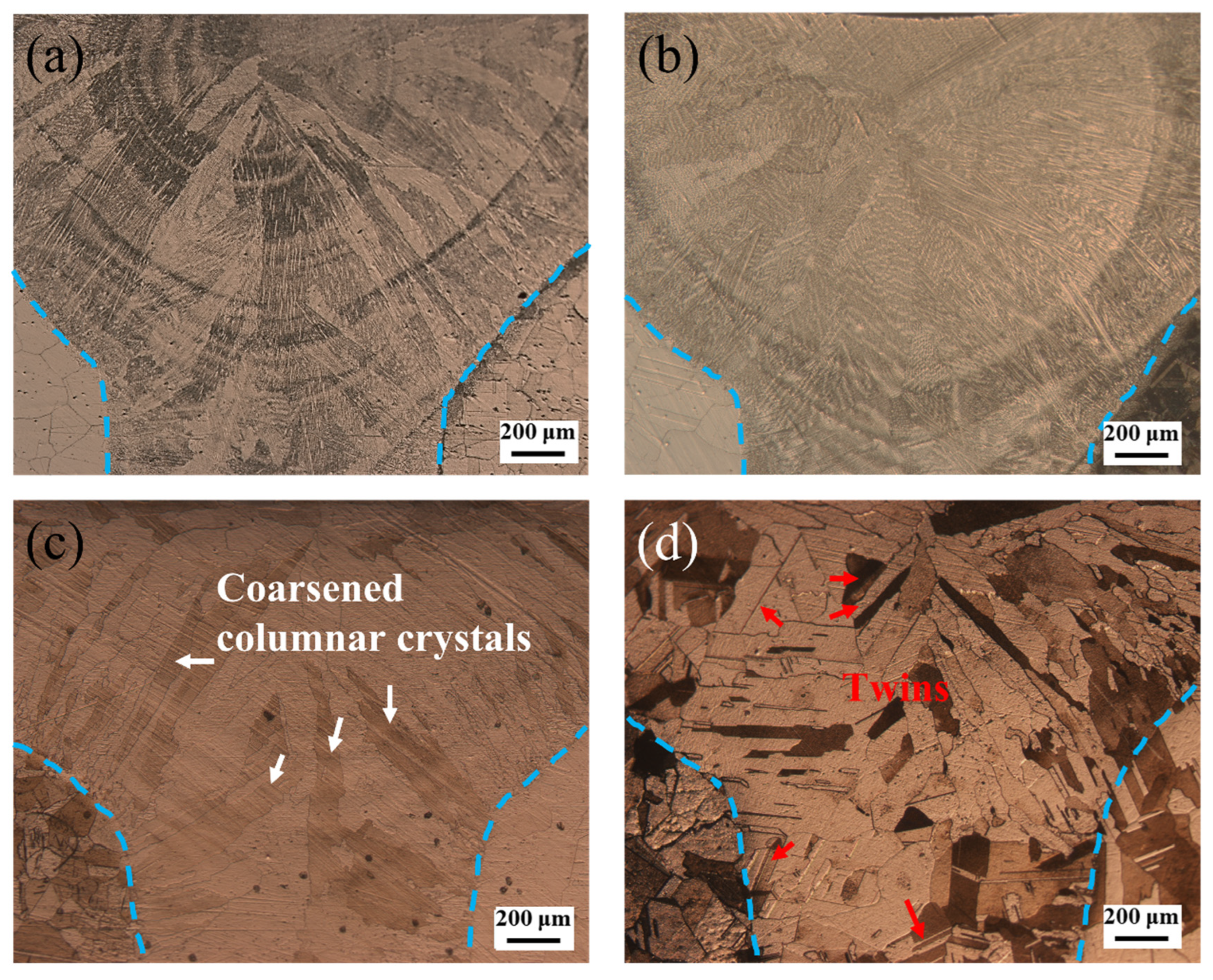
3.2. Microstructure after EBW

The overall and respective regional morphologies of the cross-section in the weld joint are shown in Figure 5. As can be seen from Figure 5a, the entire joint cross-section presents nails. The BMs, FZ, and HAZs can be easily distinguished due to the significant differences in microstructure, as shown in Figure 5b. Numerous twins are observed on both sides of the BMs away from the FZ, and comparatively fewer in the GH4169 BM away from the FZ. In addition, the grain size of IC10 BM is about 60 μm, and that of GH4169 BM is about 130 μm. During welding, the BM is barely affected on both sides away from the FZ, consistent with the pre-weld microstructure. The FZ mainly consists of columnar grains growing in the direction of near-vertical two-side fusion lines (FL, the demarcation line between the FZ and HAZ) towards the center of the FZ (as shown by the red line segments in Figure 5b), cellular structures and columnar crystals growing along a near-vertical direction near the center (as shown by the green line segments in Figure 5b).
The grain information during the solidification process in the FZ was obtained by EBSD, as shown in Figure 6. It was observed that the columnar grains are coarse and larger in the FZ (inside the black dotted frame) near the IC10 side (Region I), and the grains are in a competitive growth mode, and their orientations are concentrated in the near {101} plane, with a LAGB (low-angle grain boundary) percentage of 27.13%. By comparison, the columnar grains in the FZ near the GH4169 side (Region II) are finer and in an epitaxial growth mode, with a LAGB percentage of 20.93%. Inside the black dashed and white dashed lines are both sides of the HAZ, which is formed by the recrystallization of unmelted BMs grains near the FZ due to the influence of welding heat during the welding process, and the width of the HAZ on the GH4169 side is greater than the width on the IC10 side.
Figure 7 shows the SEM morphologies of the various regions of the joint, with the second phases present in both the BMs and FZ regions, where the second phase in BMs is distributed within the grain and near the grain boundaries. The second phases in the FZ are not uniformly distributed (shown in Figure 7b), showing an aggregated or discrete distribution (Figure 7c). There are two types of second phases with different contrasts, and the shape of these second phases is significantly smaller than that in the BM on both sides, so it can be inferred that the second phases in the FZ were formed during the solidification of the weld process. Combined with the EDS analysis (as shown in Table 2) of the second phases and the Refs. [27,28,29], it is considered that the second phase in IC10 BM is a rich-Cr carbon-boride phase (Point A), the bright second phase in FZ is considered to be a rich-Ni-Cr-Nb Laves phase (Point B), while the darker second phase is a rich-Nb, Ti carbon-boride phase (Point C), and the second phase in GH4169 BM is a Ti-rich carbon-boride phase (Point D). It is worth noting that the formation of the Laves phase is related to the segregation of Nb elements. Adam Kruk et al. [11] believe that the eutectic reaction L → (γ + NbC + Laves phase) occurs during the solidification process of nickel-based superalloys containing Nb elements, and the formation of the Laves phase is attributed to the segregation of Nb elements, and the C atoms with a high segregation tendency form MC-type carbides with strong carbides such as Ti and Nb, and the eutectic reaction occurs in the dendrite to form γ phases in the final stage of solidification. To study the elemental segregation behavior of the welded joint during solidification, the element distributions in the area adjacent to the FL on both sides were scanned using EPMA, as shown in Figure 8. During the solidification process of welding, Mo elements are enriched in the columnar grains grown directly from the FLs, and Nb and Ti were enriched in the interstitial region of this columnar grains, which means that in the initial stage of welding, a large number of Mo elements are dissolved in the γ matrix, while Nb and Ti elements are pushed into the residual liquid phase and form the inter-dendritic region during the subsequent solidification process.
The internal microstructure of the FZ is further observed using TEM, as shown in Figure 9. Figure 9a shows a rhomboidal primary phase with a size of about 400–500 nm and its high-angle annular dark field (HAADF) morphology, which is shown to include rich-Nb-Ti and poor-Cr MC-type carbides according its EDX mapping. Furthermore, numbers of dislocations are observed around the MC-type carbide in Figure 9b. Large-sized brittle Laves phases are observed in Figure 9c, and the brittle Laves phases are prone to crack initiations and extensions at the γ/Laves-phase interface. After the welding process, no γ′ and γ″ precipitates are observed in the FZ. Overall, the Laves phase and MC-type carbides form in the FZ during welding, while no nano γ′ and γ″ precipitates form.

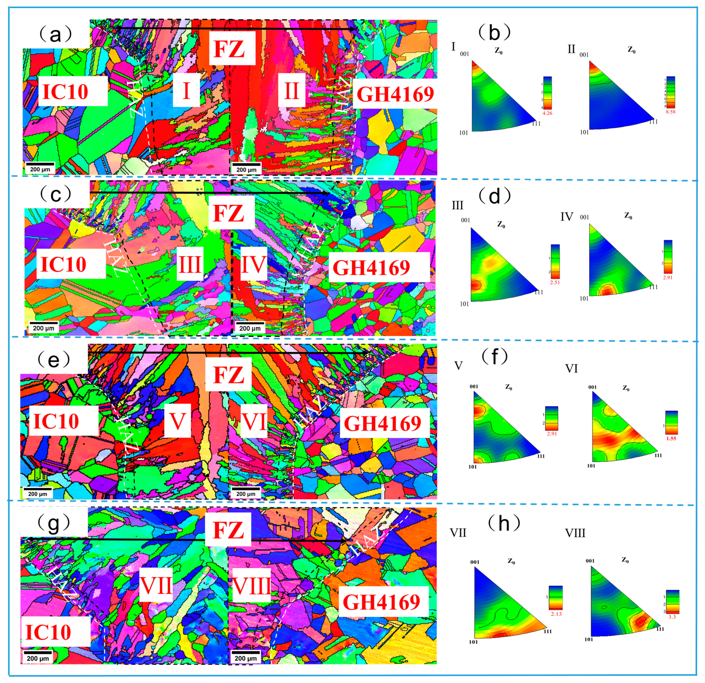
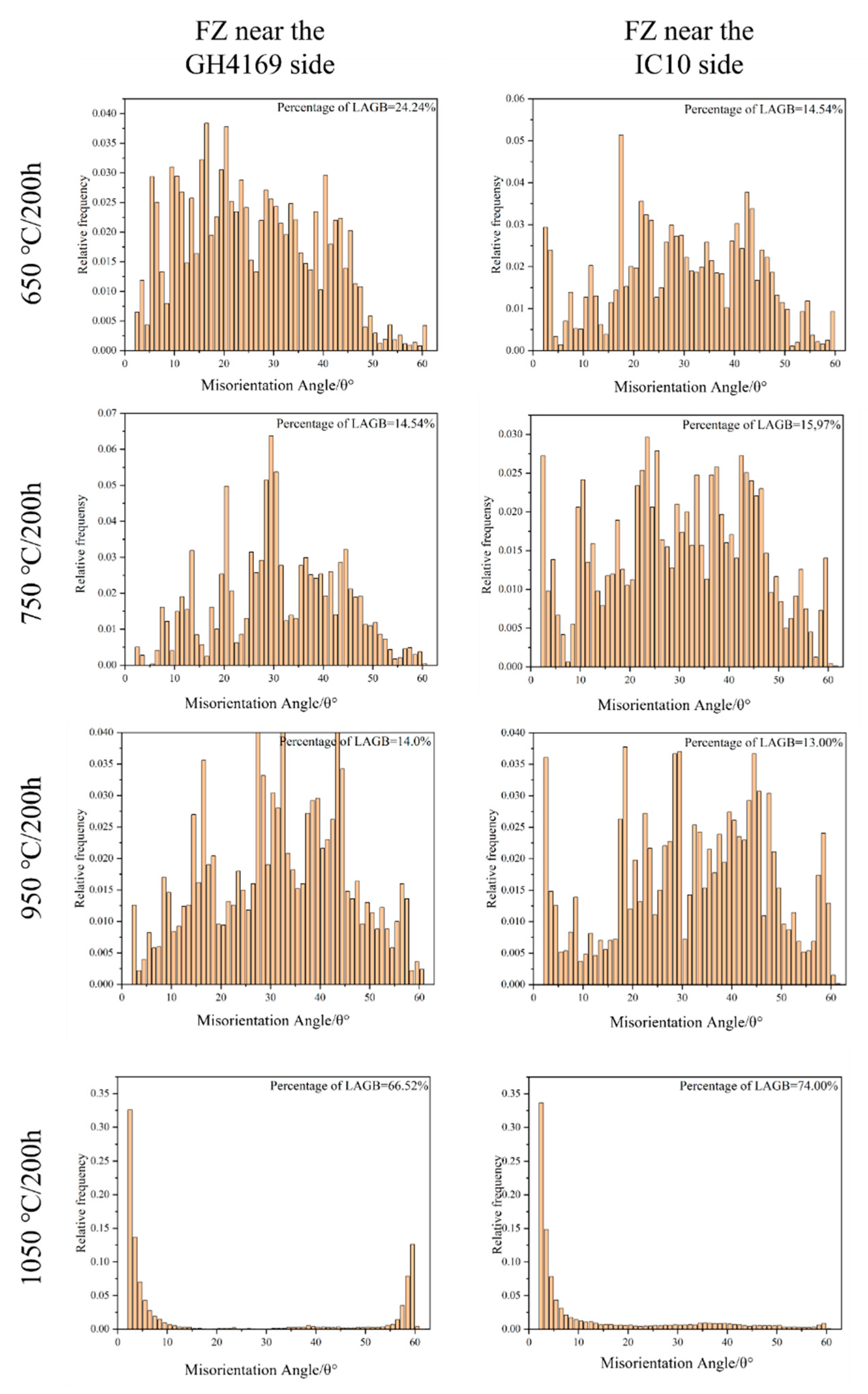
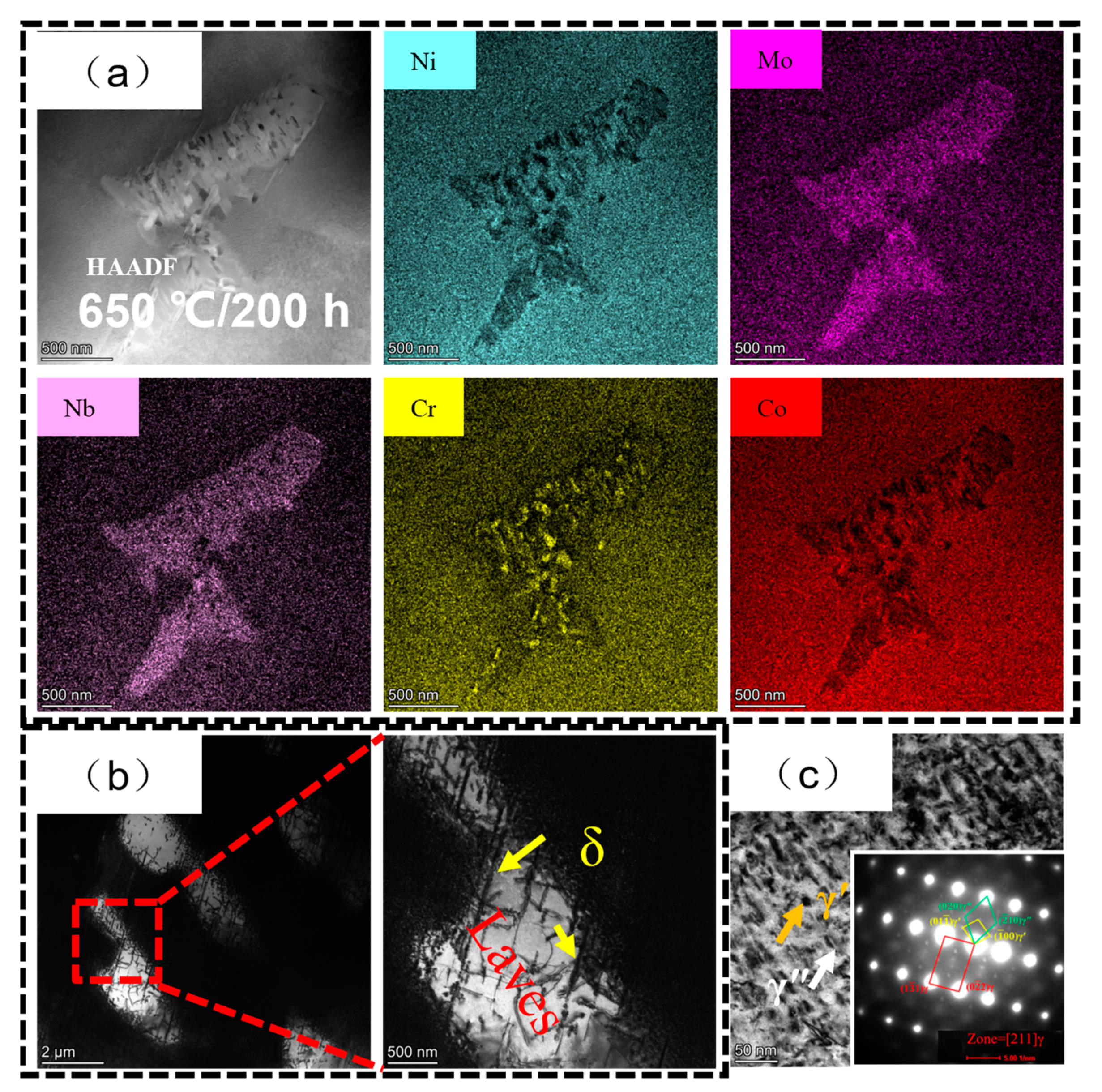
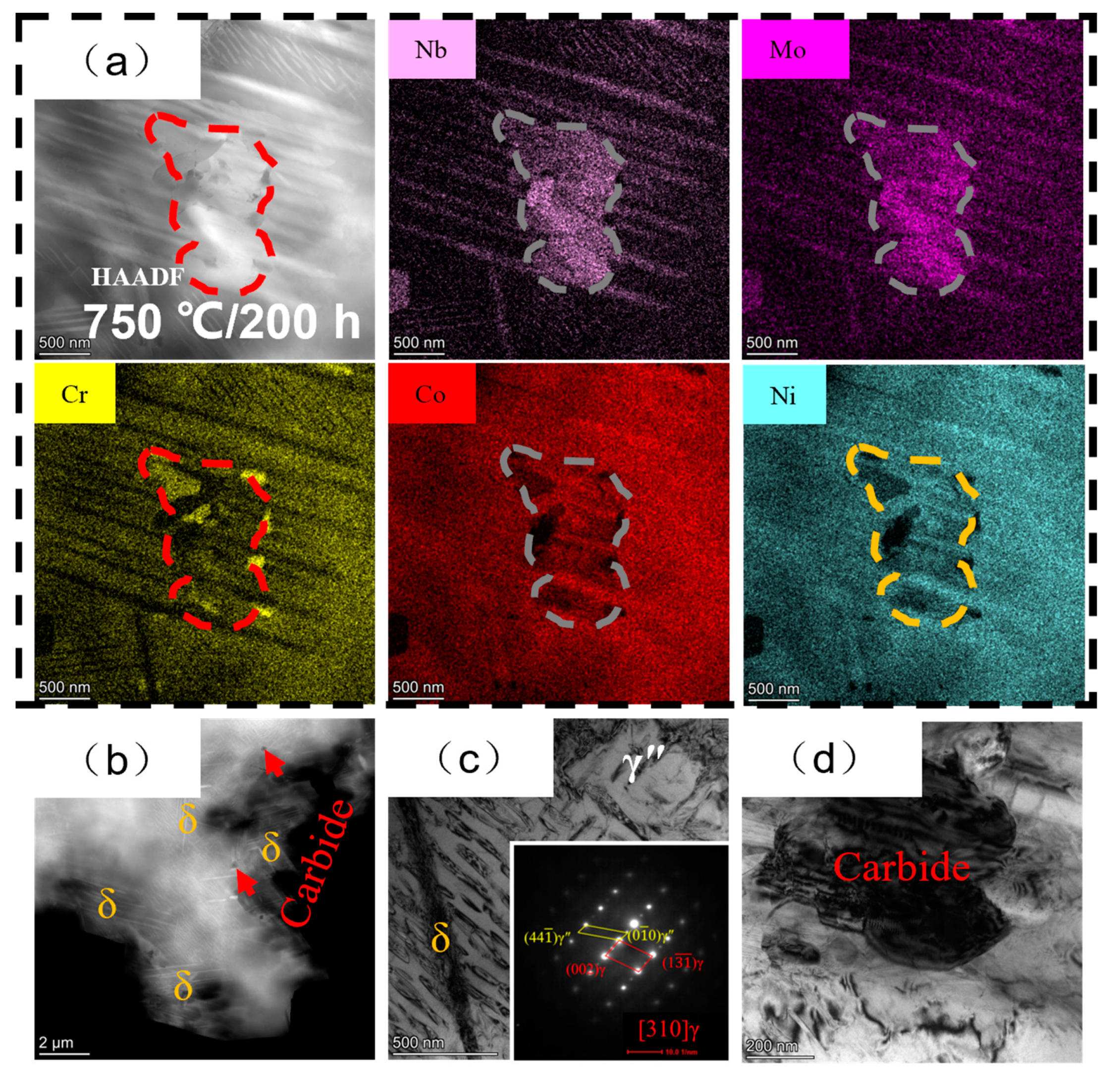
3.3. Microstructure Variations of Welded Joints after Heat Exposures

The overall morphologies of the welded joint in the cross-section after 200 h of heat exposure are shown in Figure 10, and it can be seen that the whole joint cross-section is still nail-shaped. After heat exposure at 650 °C and 750 °C, the FZ shows many slender columnar crystals and fine cellular structures. After exposure at 950 °C, the columnar crystals in the FZ are significantly coarser, and some grains with small aspect ratios appeared. When the exposure temperature increased to 1050 °C, the grain coarsening was more obvious, as numerous equiaxial crystals and coarse twins appeared in the FZ.
To further analyze the FZ after heat exposure, Figure 11 shows the EBSD images of the FZ and adjacent BM regions at different heat-exposure temperatures, which can reflect the changes in the grain orientation of the FZ under different heat exposures. When the exposure temperature is 650 °C, the grain orientation of the FZ on both sides is concentrated at {001}. As the exposure temperature reaches 750 °C, the grain orientation of the FZ on both sides is mainly concentrated near the {101}. As the heat-exposure temperature reaches 1050 °C, the FZ grains on the IC10 side do not show obvious orientations, while the FZ grains on the GH4169 side are concentrated near the {111}. The volume fractions of LAGBs and HAGBs play an important role in material properties, and a high percentage of LAGBs means a higher strain concentration upon deformation, which is detrimental to the plasticity of the FZ in the welded joint. Figure 12 shows the volume fractions of the LAGBs and HAGBs in the FZ on both sides after heat exposure, with the LAGB percentage of 24.24% on the GH4169 side of FZ and 14.54% on the IC10 side of FZ when the heat temperature reaches 650 °C. The volume fractions of the LAGBs and HAGBs in the FZ on both sides are about 15% when the heat-exposure temperature is 750 °C. The percentage of LAGB in both FZs is about 13.5% at 950 °C, and the LAGB content is very high on both sides of FZ; 66.62% on the GH4169 side and up to 74% on the IC10 side at 1050 °C.
The FZ microstructure variations after heat exposure are observed using TEM, and the microstructure of the FZ after heat exposure at 650 °C is shown in Figure 13. It can be seen that there is a complex second phase in the FZ (Figure 13a), which is enriched with Mo and Nb elements as a whole, and Ni, Cr, and Co elements in some areas, which is considered to be the Laves eutectic structure [10]. Figure 13b shows the microstructure of the Laves eutectic structure, indicating that the structure is clustered in some regions of the FZ with some needle-like δ phases, and the Laves eutectic phase has been reported to consist of the γ phase, the C14 Laves phase, the δ phase, and a monoclinic structure of the Ni7Nb2 phase [10,30]. A large number of short-rod γ″ and disc-shaped γ′ phases are observed in Figure 13c, which, combined with selective-area electron diffraction (SAED), further determined that the two phases are γ′ and γ″ phases, and that both phases are less than 50 nm in size. For comparison, Figure 14 shows the FZ microstructure of the welded joint under 750 °C heat exposure. Figure 14a shows the HAADF morphology of the Laves eutectic structure and the TEM-EDX elemental distribution, indicating the presence of a large number of long needle-like δ phases around the Laves eutectic, some of which may have grown from the δ and Ni7Nb2 phases within the Laves eutectic. Large numbers of δ-phase and bulk carbides are observed in the FZ (Figure 14b). Figure 14c shows the presence of large numbers of γ″ phases with sizes larger than 100 nm in the fusion zone and distributed around the δ phase, and the absence of the γ′ phase may be attributed to the lower dissolution temperature than that of the γ″ phase [31,32]. There are some dislocation aggregations around the carbide, while there are defects such as lattice distortion inside the carbide (Figure 14d). The microstructure of the FZ of the welded joint under heat exposure at 950 °C is shown in Figure 15. Figure 15a shows that there are some rich Nb-Mo-Ti carbide phases in the FZ, with dislocation aggregation appearing around the carbide phase (Figure 15b). Figure 15c shows the presence of large numbers of dislocations inside the FZ. Furthermore, the SAED pattern does not show superlattice diffraction (as shown in Figure 15d), indicating that the nano γ″ and γ′ phases re-dissolve into the matrix at this temperature. The microstructure of the FZ under heat exposure at 1050 °C is shown in Figure 16. Figure 16a shows the presence of rich Nb-Mo and poor Ni-Cr carbides in the FZ, surrounded by dislocation aggregation, and the subgrain boundaries are shown in Figure 16b. In Figure 16c, there are a large number of dislocations around the carbide and lattice distortion of the γ matrix. In addition, SAED (Figure 16d) shows that the nano γ″ and γ′ phases re-dissolved into the matrix at this temperature. Compared with the heat exposures of 650 and 750 °C, the higher temperature promotes the diffusion of the constituent elements (Nb, Ti, etc.) of the γ′, γ″, and δ phases, further reduces the degree of element segregation between the dendrites, and facilitates the dissolution of these elements into the γ austenite matrix, resulting in the absence of γ′, γ″, and δ phases observed.

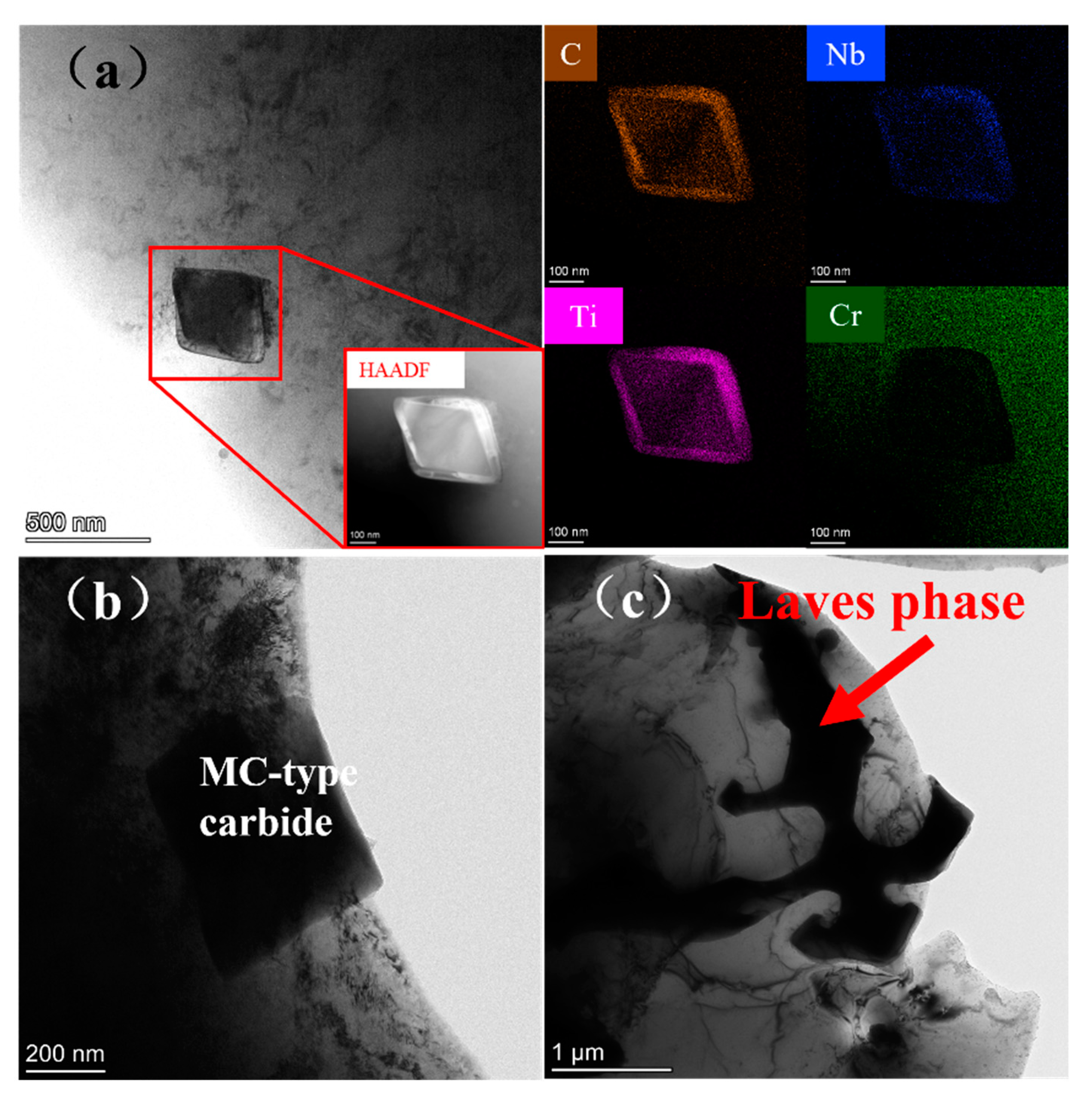
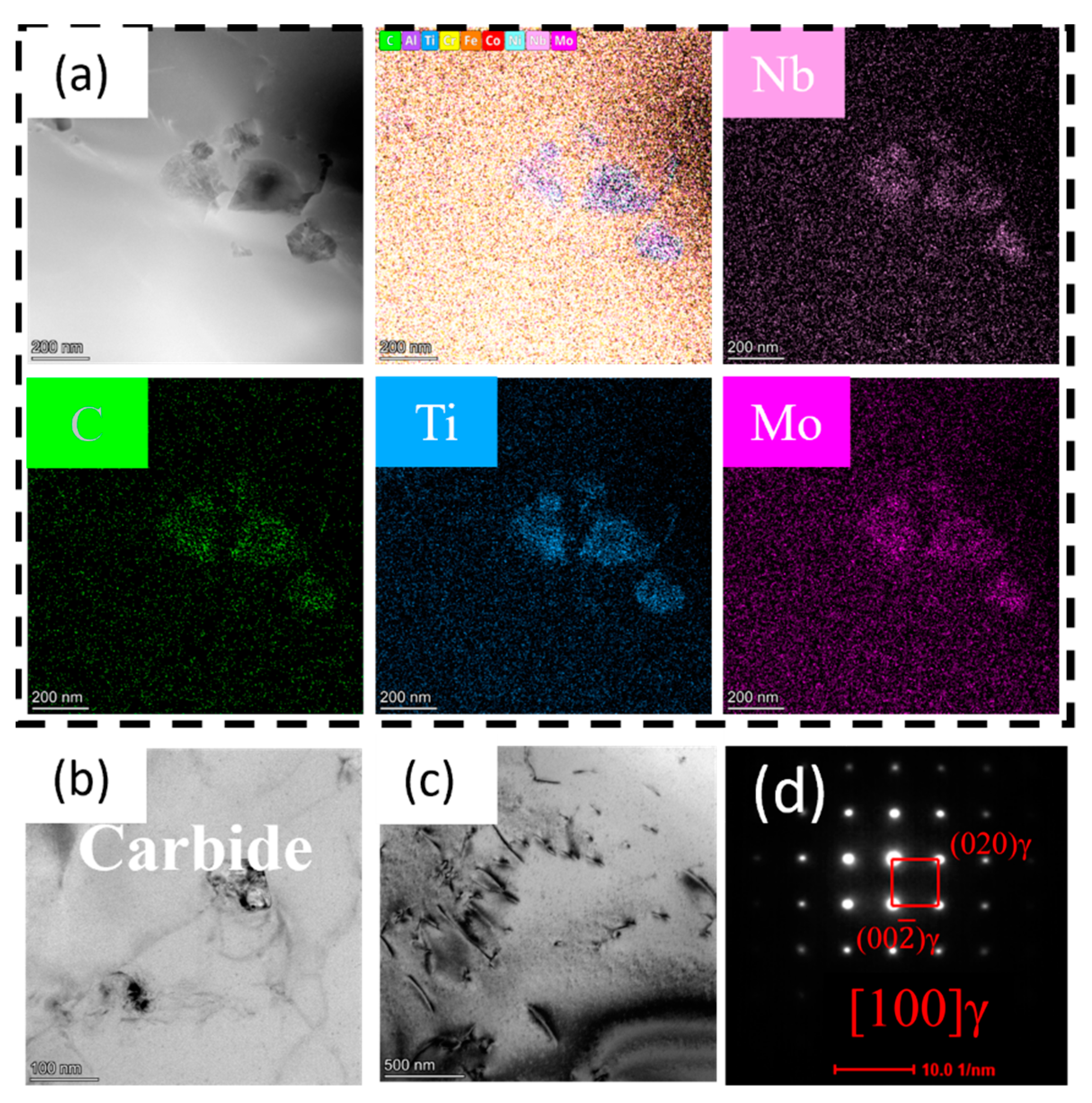
3.4. Precipitated Phases Analysis of the FZ

Figure 17 shows the SEM morphologies of the FZ at different states and a Ni-Nb-C ternary-phase diagram. Due to the aggregation of Nb, Ti and other elements in the interbranch region during the solidification process of the molten pool, the primary MC-type carbide (NbC) and Laves eutectic are concentrated in the interbranch region (Figure 17a), and a large amount of Nb remains in the γ phase between branches to form a supersaturated solid solution due to the rapid cooling of EBW. The precipitation and dissolution of the second phase in FZ are closely related to the nucleation barrier, thermal stability, and elemental content around the phase. Therefore, under thermal exposure at 650 °C and 750 °C, Nb dissolves to form γ′-Ni3(Al, Ti), γ″-Ni3Nb, and δ-Ni3Nb secondary phases, which have a relatively low nucleation barrier, while the high thermal stability of MC keeps it unchanged (Figure 17b,c). Since the C14 Laves phase in the Laves eutectic begins to dissolve at 700 °C [30], the size and morphology of the Laves eutectic change upon thermal exposure at 750 °C. The dissolution of the C14 Laves phase increases the Nb content around the eutectic, and the primary needle-like δ phase and the monoclinic Ni7Nb2 phase are similar to the δ phases in the Laves eutectic phase, and the lattice distortion and other defects in the matrix γ around the Laves eutectic provide favorable conditions for the nucleation and growth of the δ. The nucleation of δ phases at grain boundaries further indicates that crystal defects are important nucleation sites for δ phases. Although the solidification of the weld pool belongs to the non-equilibrium-solidification process, the precipitation of the second phase in the inter-dendritic region of the fusion zone after welding and under the thermal exposure at 650 °C and 750 °C can be considered as the content of Ni-Nb-C in the inter-dendritic region is near the Ni3Nb-NbC-Ni three-phase region, as the red circles and its surroundings are shown in Figure 17f.
Ge [30] concluded that the C14 Laves phase in the Laves eutectic was completely dissolved after 950 °C/30 min, while the monoclinic structure of the Ni7Nb2 phase among the Laves eutectic still maintained a high stability at 950 °C. Therefore, the Laves eutectic structure has been mostly dissolved and the numbers of large-size carbides have been significantly reduced after thermal exposure at 950 °C (Figure 17d), indicating that the long-time heat treatment at 950 °C has caused the dissolution of some of the MC carbides, and massive Nb elements re-dissolved into the γ matrix and diffused. Compared with the previous work that observed a massive δ-Ni3Nb phase in the FZ after heat treatment at 950 °C/8 h, combining this with the Ni-Nb-C phase diagram (Figure 17f), the δ-Ni3Nb-phase transition occurred at the beginning of the heat-exposure process at 950 °C. When the Nb level in the interdendrite crystal remained at a high level, the decrease in Nb level in the interdendrite crystal with the extension of the heat-exposure time promoted the transition to the high Ni and low Nb phases, resulting in the gradual dissolution of δ-Ni3Nb. At a higher temperature of 1050 °C, the MC carbide content decreases (Figure 17e), and the formation of δ-Ni3Nb is inhibited due to the high temperature and increased solubility of Nb in the γ matrix.
Figure 18 presents the schematic diagram of microstructure evolution of the FZ under different heat-exposure temperatures. The initial microstructure of the welded FZ is composed of Laves eutectic and MC carbides. After heat exposure at 650 °C, the γ′-Ni3(Al,Ti) and γ″-Ni3Nb precipitate, and there are no significant changes in the Laves eutectic and MC carbides. The γ″-Ni3Nb precipitates at 750 °C heat exposure, and the size is greater than that precipitate at 650 °C with γ″-Ni3Nb. The carbides remain stable, and there are δ-Ni3Nb precipitates at the Laves eutectic and grain boundaries after 750 °C heat exposure, and some of the δ phases “passed” the Laves eutectic, and the eutectic microstructure size decreases due to the dissolution of the C14 Laves phases inside the eutectic. Numerous studies have shown that the Laves eutectic has a high thermal stability [34,35,36]. The Laves eutectic remains at 950 and 1050 °C heat exposure, with significant a coarsening of grains at these two temperatures, as well as carbide dissolution. A small part of the large-sized carbides are present at 950 °C, while the large-sized carbides are almost invisible at 1050 °C, and γ′-Ni3(Al,Ti), γ″-Ni3Nb, and δ-Ni3Nb do not precipitate.

4. Conclusions

The dissimilar superalloys IC10/ GH4169 were joined using vacuum electron-beam welding, and the high-temperature service performance of the welded joints and the microstructure evolution of the FZ were studied. The conclusions are summarized as follows:
(1) During the solidification process of the welding pool, Mo was enriched in the inner dendrite crystal, and Nb and Ti were enriched in the interdendrite crystal. The primary phases of FZ are the Laves eutectic phase and the MC carbide phase, and no γ′ and γ″ phases are formed. During the welding process, the BMs near the melt pool recrystallize and form the welding’s heat-affected zone (HAZ);
(2) The high-temperature tensile fractures do not occur at the welded joints under different heat-exposure temperatures, indicating that the welded joints have excellent high-temperature tensile performance, and the high-temperature tensile strength of the welded joint reached 652.06 MPa under 750 °C heat exposure. The microhardness of the FZ after welding is in the range of 240~260 HV, and it is 300~320 HV when exposed to 650 °C, and then the microhardness gradually decreases with the increase in heat-exposure temperature;
(3) The Laves eutectic and MC carbides in the FZ exhibit higher stability at 650 °C and 750 °C. At 650 °C/, the γ′ and γ″ precipitate in the FZ and are less than 50 nm in size. At 750 °C, the γ″ with a size greater than 100 nm still precipitates in the FZ, and the needle-like δ phase precipitates. Some of the needle-like δ phases are distributed around and “through” the Laves eutectic of the MC carbide and Laves eutectic. High-temperature heat exposures at 950 °C and 1050 °C result in the significant coarsening of grains in the FZ and the dissolution of Laves eutectic and MC carbides. The interdendrite regions change from having a high Nb content to a high Ni content, and the high temperature further inhibits the redissolution of Nb, resulting in no δ phase precipitation.

Author Contributions

Conceptualization, J.Z. (Jiayi Zhang) and H.C.; methodology, J.H. and J.Z. (Jiayi Zhou); software, J.H. and J.Z. (Jiayi Zhou); validation, H.C., Z.M. and J.H.; formal analysis, H.C.; investigation, H.C., L.Q. and J.Z. (Jiayi Zhang); resources, H.C.; data curation, H.C. and Z.M.; writing—original draft preparation, H.C. and Z.M.; writing—review and editing, J.Z. (Jiayi Zhang) and L.Q.; visualization, H.C.; supervision, J.Z. (Jiayi Zhang); project administration, J.Z. (Jiayi Zhang); funding acquisition, J.Z. (Jiayi Zhang). All authors have read and agreed to the published version of the manuscript.

Funding

This research was funded by Jiangxi Provincial Natural Science Foundation (Grant No.: 20232BAB214015).

Data Availability Statement

No data were used for the research described in the article.

Acknowledgments

The authors are grateful for the eceshi (www.eceshi.com, accessed on 31 October 2023) for the TEM analysis.

Conflicts of Interest

The authors declare that they have no known competing financial interests or personal relationships that could have influenced the work reported in this paper.

References

  1. Han, Y. A high performance ds cast Ni3Al base alloy for advanced gas turbine blades and vanes. Acta Metall. Sin. 1995, 8, 497–502. [Google Scholar]
  2. Wang, X.; Zhao, B.; Ding, W.; Pu, C.; Wang, X.; Peng, S.; Ma, F. A short review on machining deformation control of aero-engine thin-walled casings. Int. J. Adv. Manuf. Technol. 2022, 121, 2971–2985. [Google Scholar] [CrossRef]
  3. Zhang, L.X.; Chang, Q.; Sun, Z.; Xue, Q.; Feng, J.C. Effects of boron and silicon on microstructural evolution and mechanical properties of transient liquid phase bonded GH3039/IC10 joints. J. Manuf. Process. 2019, 38, 167–173. [Google Scholar] [CrossRef]
  4. Zhang, H.; Wen, W.; Cui, H. Behaviors of IC10 alloy over a wide range of strain rates and temperatures: Experiments and modeling. Mater. Sci. Eng. A 2009, 504, 99–103. [Google Scholar] [CrossRef]
  5. Ye, R.R.; Li, H.Y.; Ding, R.G. Microstructure and microhardness of dissimilar welded joint of Ni-based superalloys IN718-IN713LC. Mater. Sci. Eng. A 2020, 774, 138894. [Google Scholar] [CrossRef]
  6. Adegoke, O.; Andersson, J.; Brodin, H.; Pederson, R. Review of Laser Powder Bed Fusion of Gamma-Prime-Strengthened Nickel-Based Superalloys. Metals 2020, 10, 996. [Google Scholar] [CrossRef]
  7. Reddy, G.M.; Murthy, C.V.S.; Rao, K.S. Improvement of Mechanical Properties of Inconel 718 Electron Beam Welds-Influence of Welding Techniques and Postweld Heat Treatment. Int. J. Adv. Manuf. Technol. 2009, 43, 671–680. [Google Scholar] [CrossRef]
  8. Huang, C.A.; Wang, T.H.; Lee, C.H. A Study of the Heat- Affected Zone (HAZ) of an Inconel 718 Sheet Welded With Electron-Beam Welding (EBW). Mater. Sci. Eng. A 2005, 398, 275–281. [Google Scholar] [CrossRef]
  9. Sonar, T.; Balasubramanian, V.; Malarvizhi, S. An Overview on Welding of Inconel 718 Alloy -Effect of Welding Processes on Microstructural Evolution and Mechanical Properties of Joints. Mater. Charact. 2021, 174, 110997. [Google Scholar] [CrossRef]
  10. Aminzadeh, A.; Parvizi, A.; Safdarian, R.; Rahmatabadi, D. Comparison between laser beam and gas tungsten arc tailored welded blanks via deep drawing. Proc. Inst. Mech. Eng. 2021, 235, 673–688. [Google Scholar] [CrossRef]
  11. Kruk, A.; Cempura, G. Decomposition of the Laves phase in the fusion zone of the Inconel 718/ATI 718Plus® welded joint during isothermal holding at a temperature of 649 °C. Mater. Charact. 2023, 196, 112560. [Google Scholar] [CrossRef]
  12. Sui, S.; Chen, J.; Zhang, R.; Ming, X.; Liu, F.; Lin, X. The tensile deformation behavior of laser repaired Inconel 718 with a non-uniform microstructure. Mater. Sci. Eng. A 2017, 688, 480–487. [Google Scholar] [CrossRef]
  13. Sui, S.; Jing, C.; Ma, L.; Wei, F.; Xin, L. Microstructures and stress rupture properties of pulse laser repaired Inconel 718 superalloy after different heat treatments. J. Alloys Compd. 2018, 770, 125–135. [Google Scholar] [CrossRef]
  14. Zhang, Y.C.; Li, Z.G.; Nie, P.L. Effect of ultrarapid cooling on microstructure of laser cladding IN718 coating. Surf. Eng. 2013, 29, 414–418. [Google Scholar] [CrossRef]
  15. Nie, P.L.; Ojo, O.A.; Li, Z.G. Numerical modeling of microstructure evolution during laser additive manufacturing of a nickel-based superalloy. Acta Mater. 2014, 77, 85–95. [Google Scholar] [CrossRef]
  16. Zhang, Y.; Li, Z.; Nie, P.; Wu, Y. Effect of heat treatment on niobium segregation of laser-cladded IN718 alloy coating. Metall. Mater. Trans. A 2012, 44, 708–716. [Google Scholar] [CrossRef]
  17. Saju, T.; Velu, M. Characterization of Welded Joints of Dissimilar Nickel-Based Superalloys by Electron Beam and Rotary Friction Welding. J. Mater. Eng. Perform. 2022, 31, 9462–9480. [Google Scholar] [CrossRef]
  18. Zhang, G.; Chen, G.; Cao, H.; Zhang, B.; Dong, Z.; Huang, Y. Electron beam offset welding to ameliorate metallurgical compatibility and mechanical performance of refractory metal/Ni-base superalloy dissimilar alloys: Nb/GH3128. Mater. Sci. Eng. A 2022, 840, 142966. [Google Scholar]
  19. Kwon, S.I.; Bae, S.H.; Do, J.H. Characterization of the Microstructures and the Cryogenic Mechanical Properties of Electron Beam Welded Inconel 718. Metall. Mater. Trans. A 2015, 47, 777–787. [Google Scholar] [CrossRef]
  20. Ram, G.D.; Reddy, A.V.; Rao, K.P. Microstructure and mechanical properties of Inconel 718 electron beam welds. Mater. Sci. Technol. 2005, 21, 1132–1138. [Google Scholar] [CrossRef]
  21. Wang, X.; Wang, H.; Qiu, Y.; Yu, S.; Zhao, Y.; Xie, M.; Zhang, B. Formability behavior, microstructural evolution, and mechanical properties of GH4169 and electroformed Ni electron beam welded joint. Vacuum 2022, 204, 111379. [Google Scholar]
  22. Ling, L.S.B.; Yin, Z.; Hu, Z. Effects of the γ″-Ni3Nb Phase on Mechanical Properties of Inconel 718 Superalloys with Different Heat Treatments. Materials 2019, 13, 151. [Google Scholar] [CrossRef] [PubMed]
  23. Liu, H.; Zhao, X.; Yuan, Y.; Dang, Y.; Li, W.; Xu, J.; Cheng, Y.; Yue, Q.; Gu, Y.; Zhang, Z. Influence of thermal exposure on microstructural stability and tensile properties of a new Ni-base superalloy. J. Mater. Res. Technol. 2022, 21, 4462–4472. [Google Scholar] [CrossRef]
  24. He, Y.; Xiao, F.; Sun, Y. Tailoring microstructure and mechanical performance of Hastelloy N-Hastelloy N superalloy joint through modifying brazing processing parameters and post thermal exposure. Mater. Charact. 2021, 173, 110947. [Google Scholar] [CrossRef]
  25. Fan, X.K.; Li, F.Q.; Liu, L. Evolution of γ′ Particles in Ni-Based Superalloy Weld Joint and Its Effect on Impact Toughness During Long-Term Thermal Exposure. Acta Metall. Sin. 2019, 33, 561–572. [Google Scholar] [CrossRef]
  26. Liu, W.; Liu, S.; Li, Y.; Li, J. Effects of Long-Term Aging on Structure Evolution and Stress Rupture Property of DD6 Single-Crystal Superalloy. Metals 2023, 13, 1063. [Google Scholar] [CrossRef]
  27. Sidhu, R.K.; Ojo, O.A.; Richards, N.L.; Chaturvedi, M.C. Metallographic and OIM study of weld cracking in GTA weld build-up of polycrystalline, directionally solidified and single crystal Ni based superalloys. Sci. Technol. Weld. Join. 2009, 14, 125–131. [Google Scholar] [CrossRef]
  28. Sabol, G.P.; Stickler, R. Microstructure of nickel-based superalloys. Phys. Status Solidi 1969, 35, 11–52. [Google Scholar] [CrossRef]
  29. Jiang, H.; Xiang, X.; Dong, J. The morphology and characteristics evolution of MC carbide during homogenization in hard-to-deform superalloy GH4975. J. Alloys Compd. 2022, 929, 167086. [Google Scholar]
  30. Ge, H.; Xing, W.; Chen, B. A new refractory Ni7Nb2 phase identified in Laves eutectic regions by TEM study. Acta Mater. 2021, 214, 116985. [Google Scholar] [CrossRef]
  31. Hong, S.J.; Chen, W.P.; Wang, T.W. A diffraction study of the γ″ phase in INCONEL 718 superalloy. Metall. Mater. Trans. A 2001, 32, 1887–1901. [Google Scholar] [CrossRef]
  32. Sundararaman, M.; Mukhopadhyay, P.; Banerjee, S. Some aspects of the precipitation of metastable intermetallic phases in INCONEL 718. Metall. Trans. A 1992, 23, 2015–2028. [Google Scholar] [CrossRef]
  33. Stadelmier, H.H.; Fiedler, M.L. The Ternary System Nickel-Niobium-Carbon/Das Dreistoffsystem Nickel-Niob-Kohlenstoff. Z. Fuer Met. 1975, 66, 224–225. [Google Scholar] [CrossRef]
  34. Sohrabi, M.J.; Mirzadeh, H. Revisiting the diffusion of niobium in an as-cast nickel-based superalloy during annealing at elevated temperatures. Met. Mater. Int. 2020, 26, 326–332. [Google Scholar] [CrossRef]
  35. Miao, Z.; Shan, A.; Wu, Y.; Lu, J.; Xu, W.; Song, H. Quantitative analysis of homogenization treatment of INCONEL718 superalloy. Trans. Nonferrous Met. Soc. China 2011, 21, 1009–1017. [Google Scholar] [CrossRef]
  36. Achmad, A.; Khaliq, A.K.; Joel, A. Microstructural study of keyhole TIG welded nickel-based superalloy G27. Mater. Charact. 2023, 204, 113178. [Google Scholar]
Figure 1. Overall morphologies of the welded plate (a) top and (b) bottom, and (c) localized enlargement of the top of the welded joint.
Metals 14 00348 g001
Figure 2. Schematic diagram of electron-beam welding and dimensions of high-temperature tensile specimen.
Metals 14 00348 g002
Figure 3. Microhardness variations of welded joints after different heat-exposure temperatures for 200 h.
Metals 14 00348 g003
Figure 4. High-temperature tensile properties of welded joints with different heat-exposure temperatures at 700 °C.
Metals 14 00348 g004
Figure 5. (a) Overall morphology of the welded joint cross-section and (b) microscopic morphology of the welded joint zones.
Metals 14 00348 g005
Figure 6. (a) EBSD images (for Z0 direction) and inverse pole figures (IPFs) of cross-sectioned welded joint and (b) percentage of misorientation angle on both sides of the FZ.
Metals 14 00348 g006
Figure 7. The SEM images of (a) IC10 BM, (b,c) FZ, and (d) GH4169 BM regions.
Metals 14 00348 g007
Figure 8. EPMA images showing element distributions in BMs and FZ regions.
Metals 14 00348 g008
Figure 9. TEM images showing the second phases of the welded joint (a) carbide and its EDX mapping, (b) MC-type carbide, (c) Laves phase.
Metals 14 00348 g009
Figure 10. OM images of welded joints after 200 h heat exposure at different temperatures: (a) 650 °C, (b) 750 °C, (c) 950 °C, and (d) 1050 °C.
Metals 14 00348 g010
Figure 11. EBSD images showing microstructure variations of welded joints after different heat-exposure temperatures: (a,b) 650 °C, (c,d) 750 °C, (e,f) 950 °C, and (g,h) 1050 °C.
Metals 14 00348 g011
Figure 12. Volume fraction of the misorientation angle (°) near the FZ on both sides at different heat-exposure temperatures.
Metals 14 00348 g012
Figure 13. TEM observations of the FZ of welded joints at 650 °C, (a) HAADF for Laves eutectic phase and EDX mapping, (b) Laves eutectic morphology, and (c) γ′ and γ″ phases and SAED pattern.
Metals 14 00348 g013
Figure 14. TEM observations of the FZ of welded joints at 750 °C (a) HAADF for Laves eutectic phase and EDX mapping, (b) HAADF for carbide and δ phases, (c) δ and γ″ phases and SAED pattern, and (d) carbide.
Metals 14 00348 g014
Figure 15. TEM observations of the FZ of welded joints at 950 °C (a) HAADF for carbides and its EDX mapping, (b) carbide morphology, (c) dislocation, and (d) SAED pattern.
Metals 14 00348 g015
Figure 16. TEM observations of the FZ of welded joints at 1050 °C (a) carbide and EDX mapping, (b) subgrain boundary, (c) carbide, and (d) SAED pattern.
Metals 14 00348 g016
Figure 17. The morphologies of the FZ for (a) as-welded heat exposures at (b) 650 °C, (c) 750 °C, (d) 950 °C, and (e) 1050 °C, respectively; (f) Ni-Nb-C ternary-phase diagram [33].
Metals 14 00348 g017
Figure 18. Schematic diagram of microstructure evolution of the FZ under different heat-exposure temperatures.
Metals 14 00348 g018
Table 1. The chemical compositions of GH4169 and IC10 alloys (wt.%).
ElementsBCCrFeMoAlTiNbCoNi
Alloys
GH4169≤0.006≤0.0817~2117~192.8~3.30.2~0.80.6~1.14.7~5.5-Bal.
IC100.01~0.02≤0.126.5~7.5-1.0~2.05.6~6.2--11~12Bal.
Table 2. The element compositions (at.%) of the points in Figure 7.
PointsCrNbTiMoNiAl
A46.26--3.2926.723.28
B18.196.793.674.4654.19-
C-85.437.493.910.06-
D17.48-85.52---
Disclaimer/Publisher’s Note: The statements, opinions and data contained in all publications are solely those of the individual author(s) and contributor(s) and not of MDPI and/or the editor(s). MDPI and/or the editor(s) disclaim responsibility for any injury to people or property resulting from any ideas, methods, instructions or products referred to in the content.

