
Influence of Submerged Entry Nozzles on Fluid Flow, Slag Entrainment, and Solidification in Slab Continuous Casting
1
State Key Laboratory of Advanced Metallurgy, University of Science and Technology Beijing, Beijing 100083, China
2
Rizhao Steel Yingkou Medium Plate Co., Ltd., Yingkou 115005, China
3
School of Metallurgical Engineering, Anhui University of Technology, Maanshan 243002, China
*
Author to whom correspondence should be addressed.
Metals 2024, 14(3), 349; https://doi.org/10.3390/met14030349
Submission received: 29 January 2024
/
Revised: 7 March 2024
/
Accepted: 13 March 2024
/
Published: 18 March 2024
(This article belongs to the Special Issue Inclusion Metallurgy (2nd Edition))
Abstract
:In this paper, the fluid flow, slag entrainment and solidification process in a slab mold were studied using physical modeling and numerical simulation. The effect of two types of submerged entry nozzles (SENs) was also studied. The results showed that the surface velocity for type A SEN was larger than that using type B SEN. For type A SEN, the maximum surface velocity was 0.63 m/s and 0.56 m/s, and it was 0.20 m/s and 0.18 m/s for type B SEN. The larger shear effect on the top surface made the slag at narrow face impacted to the vicinity of 1/4 wide face, while the slag layer at the top surface was relatively stable for type B SEN. Increasing the immersion depth of SEN decreased the surface velocity and slag entrainment. For type A SEN, the thickness of the solidified shell at the narrow face of the mold outlet was thin (12.3 mm) and there was a risk of breakout. For type B SEN, the liquid steel with high temperature would flow to the meniscus and it was beneficial to the melting of the mold flux. The thickness of the solidified shell at the narrow face of the mold outlet was increased. Furthermore, the surface velocity was also increased and it was not recommended for high casting speed.
1. Introduction
The stability of continuous casting mold is crucial for the quality control of the slab and the efficiency of the continuous casting production. The submerged entry nozzle (SEN) is an important component in the continuous casting process of steel, specifically in the mold [1]. It plays a critical role in controlling the flow pattern of liquid steel, as well as maintaining the overall quality and efficiency of the casting operation [2,3]. The structure of the SEN is designed to enable the molten metal to enter the mold in a controlled and uniform manner [4]. Additionally, the SEN could also control the flow rate and prevent excessive turbulence during the casting process.
This is achieved through the use of varying nozzle sizes, allowing for adjustments in the flow characteristics based on the specific requirements of the casting operation. The control process ensures a stable, consistent flow of liquid steel into the mold, aiding in the prevention of defects such as surface cracks or internal porosity [5,6,7]. Furthermore, the optimal design and configuration of the SEN ensure the production of high-quality steel products [8].
The commonly used nozzle structure in a slab mold is a double-hole submerged nozzle. The submerged nozzle controls the flow pattern of the liquid steel in the mold. If the design of the nozzle is unreasonable, the liquid steel may produce large liquid level fluctuations, and even the thickness of the shell at the mold outlet will be reduced, resulting in a steel leakage accident [9,10,11]. The SEN plays an important role in the fluid flow, heat transfer, solidification process, and slab surface quality in the mold [12,13,14,15].
Many investigations have been reported through physical modeling. Szekely and Yadoya [16] studied a single-hole straight-through SEN and a side-hole SEN. It was found that the side-hole SEN was more conducive to remove non-metallic inclusions by comparing the fluid flow and surface velocity. Bielnicki and Jowsa [17] adopted silicon oil and polypropylene particles to simulate the liquid slag layer and mold flux slag layer. They found that the effect of the mold flux layer on the slag-type inclusion could not be ignored. Jeon et al. [18] analyzed the fluid flow, liquid level fluctuation, and generation mechanism of the vortex using the funnel-shaped nozzle. Li and Tsukihashi [19,20] analyzed the eddy current in the mold, and obtained that the flow of liquid steel, inclination angle of the SEN, and casting speed had a significant influence on the eddy current. Jin et al. [21] found that the solidified shell made the liquid level fluctuation more intense, the surface velocity higher, and the uniformity worse in the mold.
Recently, the authors observed a large liquid level fluctuation in a slab continuous casting mold in industrial production. It may lead to slag entrainment and quality defects. In this work, the fluid flow, slag entrainment, and solidification process in the slab mold were studied. The effect of two types of SENs was compared and discussed.
2. Experimental Work
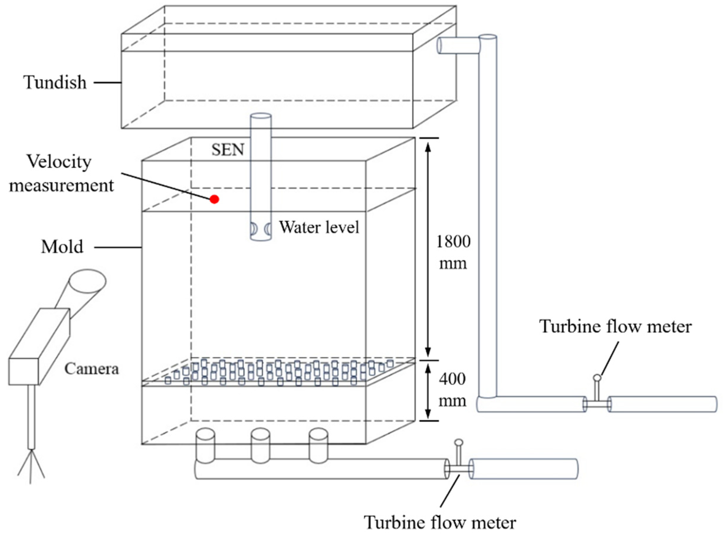
A full-scale water model of the slab mold was built with transparent plexiglass. The height of the mold was 900 mm. To avoid the influence of the reversed flow on the flow field in the mold, the model was extended to 2200 mm, as shown in Figure 1. The level fluctuations at three different positions were measured through a wave-height sensor (DJ 800, produced by China Institute of Water Resources and Hydropower Research). The three positions are located near the SEN exit, at 1/4 mold width, and near the narrow face, respectively. Two types of SENs were considered, as shown in Figure 2. They were named as type A and type B, respectively. Both of them have racetrack ports. Type A SEN is widely used for continuous casting of slab. Type B is a newly designed one, whose bore and port sizes are larger than that of type A. A probe anemometer is fixed at 1/4 mold width to measure the surface velocity in water model, as shown in Figure 1. The dimensions and parameters of the prototype and water model are listed in Table 1.
The flow rate in the water model is calculated based on the Froude similarity criterion.
where Qm is the flow rate in the model (m3/h), Qp is the flow rate in the prototype (m3/h). The subscripts m and p represent the model and the prototype, respectively.
Qm = Qp
Based on Equation (1), the flow rate in the water model was 26.4 m3/h. The physical properties of each phase in the prototype and water model are shown in Table 2. During experiments, the flow rates at the tundish inlet and the mold bottom were controlled through the turbine flow meter. The adjustment of a stopper rod was used to stabilize the liquid level. The liquid level remained almost unchanged for 5 min. After that, the level fluctuations in the water model were measured using the DJ 800 equipment. The measured data were collected for 50 s. Each experiment was repeated three times. To display the fluid flow in the mold, ink tracer experiments were conducted. Furthermore, a commercial silicon oil was added to the water model to study the movement of the slag phase. The oil phase was determined based on the viscosity ratio, as shown in Equation (2). The thickness of the oil phase was 15 mm and its movement was recorded using a CCD camera during experiments.
where μslag is the viscosity of the slag (Pa·s), μsteel is the viscosity of liquid steel (Pa·s), μoil is the viscosity of the oil phase (Pa·s), and μwater is the viscosity of water (Pa·s).
The three-dimensional (3-D) single-phase transient fluid flow, heat transfer, and solidification in the mold were modeled by calculating the continuity equation, Navier–Stokes equations, realizable k-ε turbulence model, energy equation, and solidification equations. The energy conservation equation is expressed by
where ρ is the fluid density (kg/m3), H is the enthalpy (J/kg), ui is the fluid velocity at direction i (m/s), t is time (s), xi is the coordinate at direction i (m), keff is the effective thermal conductivity (W/m/K), and T is the temperature (K).
The enthalpy-porosity technique was used to track the liquid–solid front [24,25]. The liquid–solid mushy zone is treated as a porous zone. It uses the liquid fraction to describe the mushy zone. The liquid fraction β is defined as
where Ts is the solidus temperature of the steel (K), and Tl is the liquidus temperature of the steel (K).
The solidification of liquid steel would lead to the losses of momentum and turbulence, which were considered by adding a source term to the momentum equation and turbulence equation. The momentum source term Sm is represented as
where Amush is the mushy zone constant, and uC is the casting speed (m/s).
The turbulence source term St is described as
where ϕ is the turbulence quantity.
In this work, the system of equations was solved by a commercial CFD software (Fluent version 14.0) [26]. Considering the symmetry of the liquid steel flow, only half of the geometric model was built as a computational domain, as shown in Figure 3. The inlet velocity of the SEN was calculated according to the casting speed and cross-sectional area of the slab. The casting temperature was set as 1816 K (1543 °C). The outflow boundary condition was set at the domain bottom. The top surface of the mold was treated as a free surface with a zero-shear stress. Non-slip conditions were chosen at the walls. The heat fluxes at the narrow and wide faces of the mold were obtained according to the flow rate and temperature difference of cooling water in the mold walls. The convection and mixed heat transfer conditions were set at wide and narrow faces of the extended region, respectively. The standard wall functions were used to model the turbulence characteristics in the near-wall region. The PISO scheme was used for the pressure-velocity coupling [26]. The convergence criterion for the energy equation was set to 10−6 and 10−4 for other variables. The time step was 0.001 s. All computations were performed on a Windows 10 PC with Intel 3.5 GHz CPU and 512 GB RAM. The parameters of liquid steel and heat transfer conditions in numerical simulations are listed in Table 3.
3. Results and Discussion
3.1. Fluid Flow and Surface Velocity
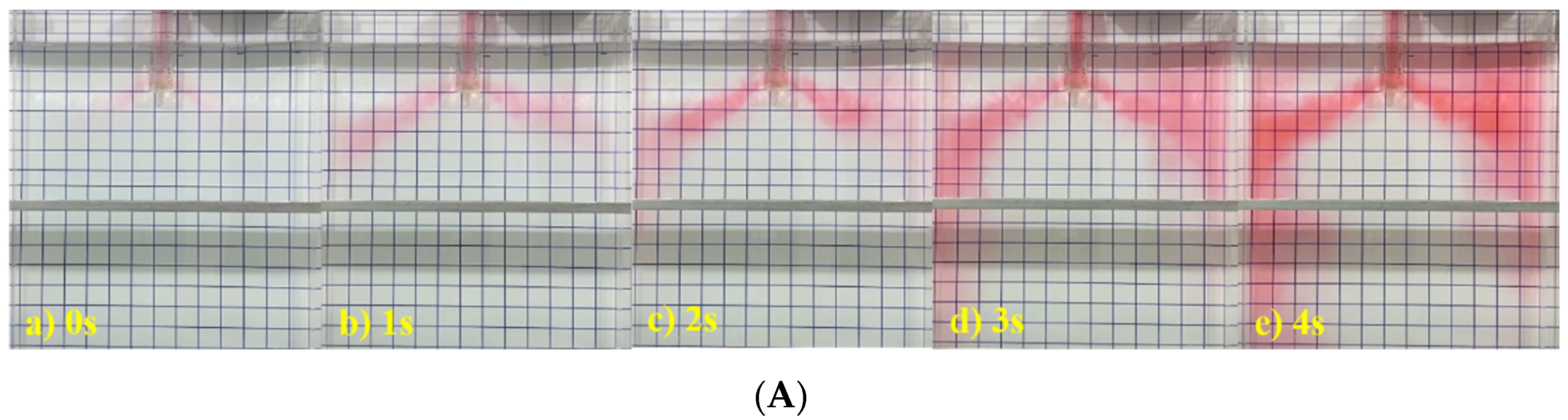
Figure 4 shows the fluid flow in the mold at different moments using type A SEN. The casting speed was 1.5 m/min and the immersion depth of the SEN was 120 mm, 150 mm, and 170 mm, respectively. Obviously, a similar flow pattern could be observed. The flow stream from the SEN exit formed upper flow and lower flow after impacting the narrow face. The flow stream had a larger spreading angle and was more dispersed, impacting a larger area on the narrow face. When the immersion depth was 120 mm, the flow stream impacted the narrow face at around 2.1 s and 2.0 s for the immersion depth of 150 mm. Moreover, it was about 2.3 s for the immersion depth of 170 mm. Increasing the immersion depth increased the impact depth of the flow stream.
At 1 s, the ink from the SEN exit flowed towards the narrow face of the mold. At 3 s, the ink reached the narrow face completely, and then the flow stream could be divided into two parts after impacting the narrow face. The upper flow gathered at the corner of the mold and diffused towards the center position.
Figure 5 shows the fluid flow in the mold at different moments using type B SEN. It can be seen that the time of the flow stream impacting the narrow face was 3 s when the immersion depth was 120 mm and 2 s for the immersion depth of 150 mm. It was 3 s when the immersion depth was increased to 170 mm. Similarly, as the immersion depth of the SEN increased, the impact depth of the flow stream increased and the liquid level fluctuation was relatively small.
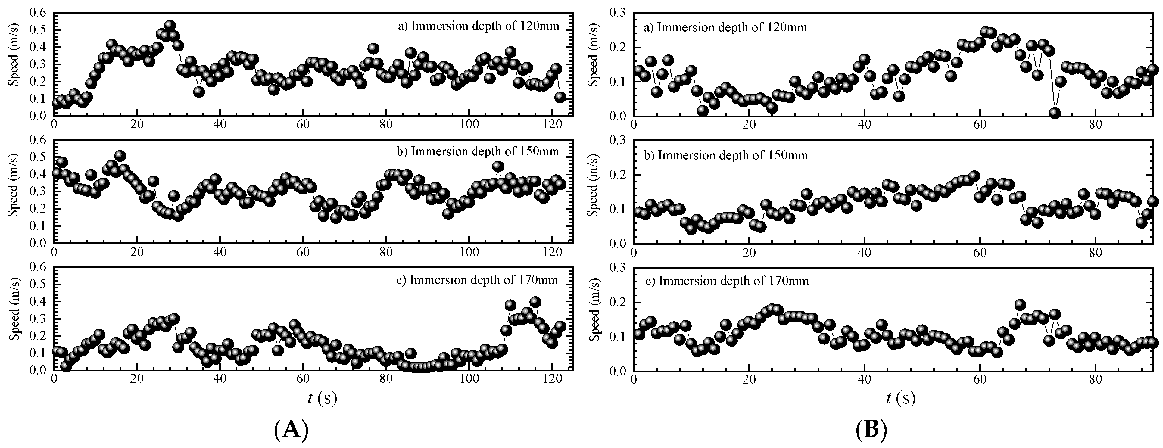
Figure 6 shows the velocity distribution of top surface at 1/4 wide face of the mold. The casting speed was 1.5 m/min and the immersion depth of the SEN was 120 mm, 150 mm, and 170 mm. As can be seen from Figure 6A, the surface flow velocity was in the range of 0 to 0.55 m/s for type A SEN. In most cases, its value was less than 0.40 m/s. With the immersion depth increasing, the fraction of surface flow velocity larger than 0.40 m/s indicated a decreasing trend. When the immersion depth increased to 170 mm, the surface flow velocity was less than 0.40 m/s.
When the type B SEN was adopted, the surface flow velocity at 1/4 wide face was 0~0.25 m/s and its value was less than 0.20 m/s in most cases. For the immersion depth of 170 mm, the surface flow velocity was less than 0.20 m/s. By comparison, it was found that the surface velocity using type A SEN was higher than that using type B SEN. For both of them, increasing the immersion depth of the SEN decreased the surface flow velocity.
3.2. Level Fluctuation and Slag Entrainment
Figure 7 shows the liquid level fluctuation at casting speed of 1.50 m/min. The immersion depth of the SEN was 120 mm, 150 mm, and 170 mm, respectively. When the type A SEN was used, the maximum value of liquid level fluctuation near the nozzle was 5.27 mm for the immersion depth of 120 mm. The maximum value near 1/4 wide face was 3.62 mm and it was 2.87 mm near the narrow surface. The average liquid level fluctuation near the nozzle, 1/4 wide face, and narrow face was 1.00 mm, 0.96 mm, and 0.92 mm, respectively. For the immersion depth of 150 mm, the maximum value of liquid level fluctuation near the nozzle, 1/4 wide face, and narrow face was 5.08 mm, 3.22 mm, and 4.31 mm. The corresponding average value was 1.13 mm, 0.97 mm, and 1.01 mm. When the immersion depth of the SEN increased to 170 mm, the maximum value of liquid level fluctuation near the nozzle, 1/4 wide face, and narrow face was 3.01 mm, 3.15 mm, and 4.28 mm. Moreover, the average value was 0.93 mm, 0.92 mm, and 0.91 mm.
For the type B SEN, the liquid level fluctuation was decreased. When the immersion depth was 120 mm, the maximum value of liquid level fluctuation near the nozzle, 1/4 wide face, and narrow face was 2.59 mm, 2.57 mm, and 2.65 mm. The average value was 0.66 mm, 0.75 mm, and 0.84 mm. For the immersion depth of 150 mm, the maximum value of liquid level fluctuation near the nozzle, 1/4 wide face, and narrow face was 2.41 mm, 2.49 mm, and 2.70 mm. The corresponding average value was 0.67 mm, 0.63 mm, and 0.49 mm. When the immersion depth of the SEN increased to 170 mm, the maximum value of liquid level fluctuation near the nozzle, 1/4 wide face, and narrow face was 1.51 mm, 2.32 mm, and 2.58 mm. Additionally, the average value was 0.37 mm, 0.56 mm, and 0.57 mm, respectively.
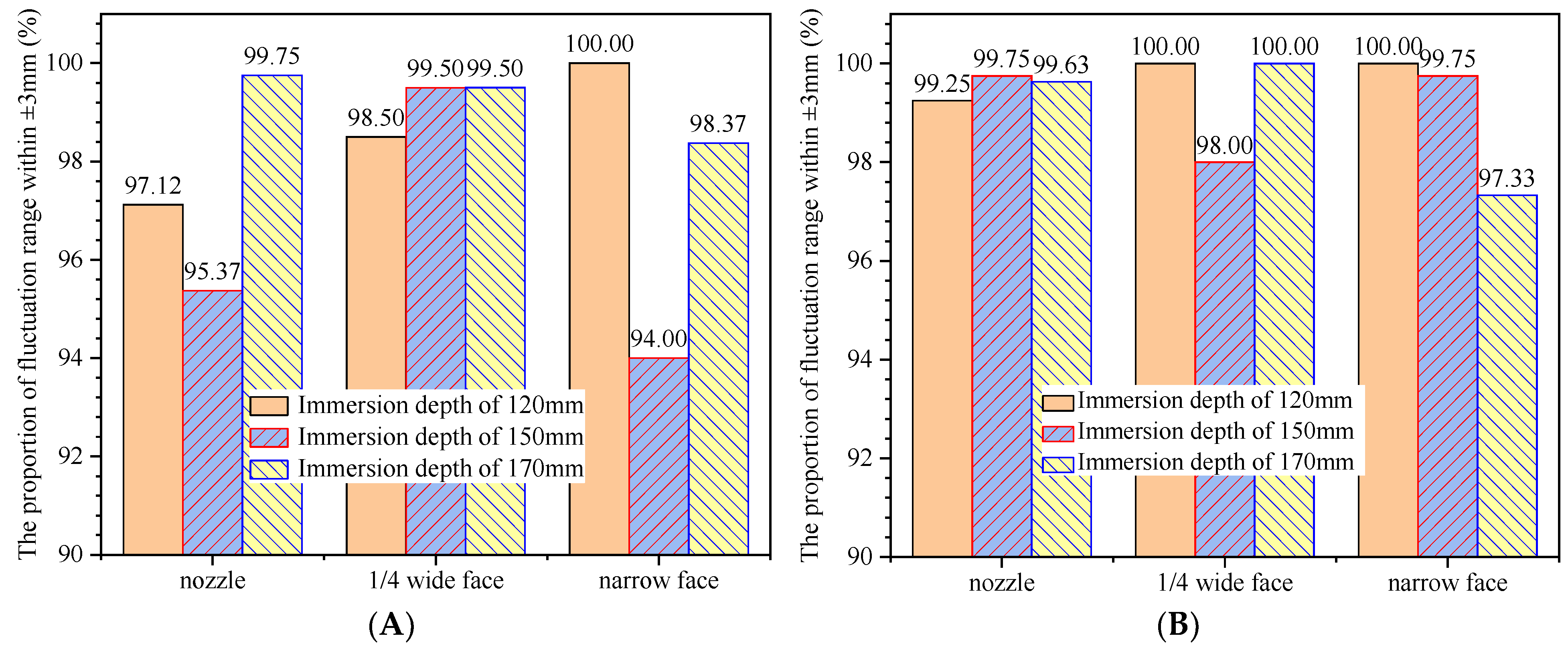
Figure 8 shows the proportion of liquid level fluctuation in the range of ±3 mm. The casting speed was 1.50 m/min. For the type A SEN, the proportion near the nozzle was 97.12% when the immersion depth was 120 mm. The proportion near 1/4 wide face and narrow face was 98.5% and 100.0%, respectively. When the immersion depth was 150 mm, the proportion near the nozzle, 1/4 wide face and narrow face was 95.37%, 99.5%, and 94.00%. For the immersion depth of 170 mm, the proportion was 99.75%, 99.5%, and 98.37%. When the type B SEN was adopted, the proportion near the nozzle was 99.25% for the immersion depth of 120 mm. The proportion near 1/4 wide face and narrow face was 100.00% and 100.0%, respectively. When the immersion depth was 150 mm, the proportion near the nozzle, 1/4 wide face and narrow face was 99.75%, 98.00%, and 99.75%. For the immersion depth of 170 mm, the proportion was 99.63%, 100.00%, and 97.33%.
Figure 9 shows the oil distribution in the mold at different SEN immersion depths. The casting speed was 1.50 m/min and the immersion depth of the SEN was 120 mm, 150 mm, and 170 mm. For the type A SEN, the surface flow velocity was large when the immersion depth of the SEN was 120 mm. Due to the shear effect, the oil phase near the narrow surface was pushed to 1/4 wide face so that the thickness of the oil phase at the top surface almost reached the limit value. For the immersion depth of 150 mm, the fluctuation of the oil phase began to weaken and its thickness increased. A small amount of oil droplets was mixed into the mold. When the immersion depth was further increased to 170 mm, the fluctuation of the oil phase was lowered. As a result, the thickness of the oil phase was also increased. For the type B SEN, a certain amount of oil droplets was entrained into the mold and the oil phase near the narrow surface was exposed when the immersion depth of the SEN was 120 mm. Increasing the immersion depth of the SEN decreased the fluctuation and entrainment of the oil phase at top surface. Moreover, the thickness of the oil phase near the narrow surface was increased.
3.3. Velocity Distribution and Shell Thickness
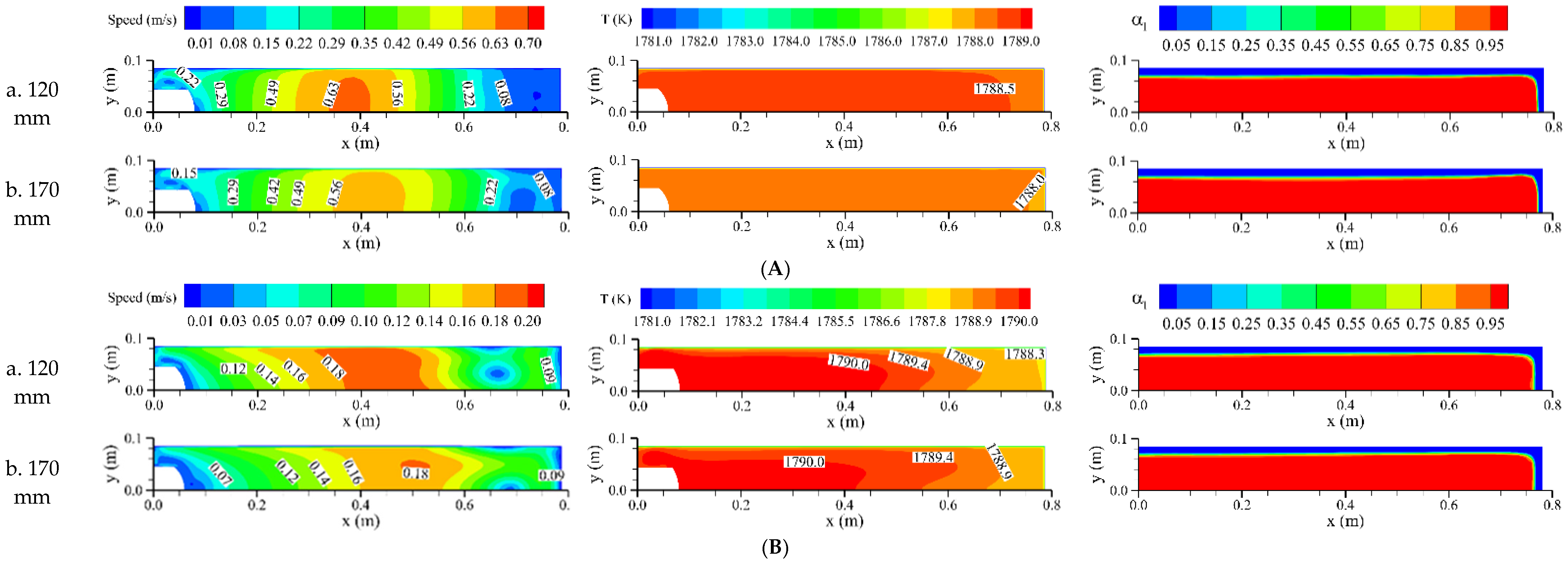
Figure 10 shows the distributions of surface velocity, temperature, and shell thickness at the mold outlet. The casting speed was 1.50 m/min and the immersion depth of the SEN was 120 mm, 150 mm, and 170 mm, respectively. For the type A SEN, the area with higher velocity was located on the right-side of 1/4 wide face. With the increase in SEN immersion depth, the disturbance of the jet to the top surface was weakened and the velocity of liquid steel decreased. The maximum velocity was 0.63 m/s and 0.56 m/s, respectively. The temperature distribution at the meniscus showed a decreasing trend and the high temperature zone was reduced. When the SEN immersion depth was 120 mm, the solidified shell thickness at the narrow face of the mold outlet was 14.3 mm and it was 16.7 mm at the wide face. When the SEN immersion depth was 170 mm, the solidified shell thickness at the narrow face of the mold outlet was reduced to 12.3 mm and it was still 16.7 mm at the wide face. For the type B SEN, the surface velocity decreased and the maximum velocity was 0.20 m/s and 0.18 m/s, respectively. Meanwhile, the high temperature zone was extended, which was beneficial to the melting of the mold flux. The thickness of the solidified shell at the narrow face of the mold outlet was increased to 16.7 mm. It was still 16.7 mm at the wide face.
Furthermore, the surface velocity using type A SEN was significantly larger than that using type B SEN. The results basically corresponded to the measured values in Figure 6, indicating that the mathematical model could be used for simulating the fluid flow, heat transfer, and solidification process in the mold.
4. Conclusions
The fluid flow, slag entrainment and solidification process in a slab mold were investigated through physical modeling and numerical simulation. The effect of two types of submerged entry nozzles (SENs) was compared. The following conclusions can be drawn:
- For type A SEN, the surface velocity was larger than that using type B SEN. The surface velocity for the immersion depth of 120 mm was higher than that of other immersion depths. With the increase in the SEN immersion depth, the velocity at the top surface was decreased.
- For type A SEN, the larger shear effect on the top surface made the slag phase at narrow face impacted to the vicinity of 1/4 wide face, while the slag phase at the top surface was relatively stable for type B SEN. When the immersion depth of 120 mm was adopted, the slag entrainment was higher than that of other immersion depths. Increasing the immersion depth of SEN decreased the slag entrainment.
- When type A SEN was used, the thickness of the solidified shell at the narrow face of the mold outlet was thin (12.3 mm) and there was a risk of breakout. For type B SEN, the liquid steel with high temperature would flow to the meniscus and it was beneficial to the melting of the mold flux. The thickness of the solidified shell at the narrow face of the mold outlet was increased.
Author Contributions
Conceptualization, X.Z.; methodology, X.Z.; software, X.Z.; validation, S.P.; formal analysis, X.Z.; investigation, S.P.; resources, S.P.; data curation, S.P.; writing—original draft preparation, X.Z.; writing—review and editing, X.Z. and J.Z.; visualization, X.Z.; supervision, S.P.; project administration, X.Z. and S.P. All authors have read and agreed to the published version of the manuscript.
Funding
This research received no external funding.
Institutional Review Board Statement
Not applicable.
Informed Consent Statement
Not applicable.
Data Availability Statement
Data available in a publicly accessible repository.
Conflicts of Interest
The authors declare no conflicts of interest.
References
- Calderón-Ramos, I.; Morales, R.D. The role of submerged entry nozzle port shape on fluid flow turbulence in a slab mold. Metall. Mater. Trans. B 2015, 46, 1314–1325. [Google Scholar] [CrossRef]
- Xu, P.; Zhou, Y.Z.; Chen, D.F.; Long, M.J.; Duan, H.M. Optimization of submerged entry nozzle parameters for ultra-high casting speed continuous casting mold of billet. J. Iron Steel Res. Int. 2022, 29, 44–52. [Google Scholar] [CrossRef]
- Fang, Q.; Ni, H.W.; Zhang, H.; Wang, B.; Lv, Z.A. The effects of a submerged entry nozzle on flow and initial solidification in a continuous casting bloom mold with electromagnetic stirring. Metals 2017, 7, 146. [Google Scholar] [CrossRef]
- Kamal, M.; Sahai, Y. Modeling of melt flow and surface standing waves in a continuous casting mold. Steel Res. Int. 2005, 76, 44–52. [Google Scholar] [CrossRef]
- Gan, M.J.; Pan, W.J.; Wang, Q.Q.; Zhang, X.B.; He, S.P. Effect of exit shape of submerged entry nozzle on flow field and slag entrainment in continuous casting mold. Metall. Mater. Trans. B 2020, 51, 2862–2870. [Google Scholar] [CrossRef]
- Wang, P.; Tie, Z.P.; Xiao, H.; Zhu, J.L.; Tang, H.Y.; Zhang, J.Q. Optimizing of submerged entry nozzle for bloom continuous casting based on physical and numerical simulation. Steel Res. Int. 2022, 93, 2200402. [Google Scholar] [CrossRef]
- Gonzalez-Trejo, J.; Miranda-Tello, J.R.; Cervantes-de-la-Torre, F.; Carvajal-Mariscal, I.; Sanchez-Silva, F.; Gabbasov, R.; Real-Ramirez, C.A. Experimental analysis of a slab continuous-casting SEN with an inner flow divider. Metals 2022, 12, 1097. [Google Scholar] [CrossRef]
- Calderón-Ramos, I.; Morales, R.D.; Salazar-Campoy, M. Modeling flow turbulence in a continuous casting slab mold comparing the use of two bifurcated nozzles with square and circular ports. Steel Res. Int. 2015, 86, 1610–1621. [Google Scholar] [CrossRef]
- Wu, D.F.; Cheng, S.S. Effect of SEN design on surface fluctuation and solidifying shell in slab mold and its optimization. Acta Metall. Sin. 2008, 21, 341–350. [Google Scholar] [CrossRef]
- Morales, R.D.; Ramos, I.C.; Campoy, M.M.S. The role of nozzle-port geometry on flux entrainment in slab molds. In Proceedings of the 6th International Congress on the Science and Technology of Steelmaking(I), Beijing, China, 12–14 May 2015; pp. 485–488. [Google Scholar]
- Morales-Higa, K.; Guthrie, R.I.L.; Isac, M.; Morales, R.D.; Labrecque, C.; Lapointe, F. The effects of fluid flow on flux entrainment in a square billet mold. In Proceedings of the AISTech 2013—Iron and Steel Technology Conference, Pittsburgh, PA, USA, 6–9 May 2013; pp. 1461–1472. [Google Scholar]
- Pang, J.C.; Qian, G.Y.; Pang, S.; Ma, W.H.; Cheng, G.G. Design of a submerged entry nozzle for optimizing continuous casting of stainless steel slab. J. Iron Steel Res. Int. 2023, 30, 2229–2241. [Google Scholar] [CrossRef]
- Zeng, J.; Chen, W.Q.; Wang, G.S.; Cao, C.F.; Gao, Y.B. Development and application of an off-line soft reduction model during continuous casting of high-carbon rectangular billet. Metall. Res. Technol. 2015, 112, 403. [Google Scholar] [CrossRef]
- Wang, Y.F.; Zhang, L.F. Fluid flow-related transport phenomena in steel slab continuous casting strands under electromagnetic brake. Metall. Mater. Trans. B 2011, 42, 1319–1351. [Google Scholar] [CrossRef]
- Ramos, I.C.; Morales, R.D.; Garcia-Hernandez, S.; Ceballos-Huerta, A. Effects of immersion depth on flow turbulence of liquid steel in a slab mold using a nozzle with upward angle rectangular ports. ISIJ Int. 2014, 54, 1797–1806. [Google Scholar] [CrossRef]
- Szekely, J.; Yadoya, R. The physical and mathematical modeling of the flow field in the mold region in continuous casting systems: Part I. model studies with aqueous systems. Metall. Trans. 1972, 3, 2673–2680. [Google Scholar] [CrossRef]
- Bielnicki, M.; Jowsa, J. Physical modeling of mold slag entrainment in continuous steel casting mold with consideration the impact of mold powder layer. Steel Res. Int. 2018, 89, 1800110. [Google Scholar] [CrossRef]
- Jeon, Y.J.; Sung, H.J.; Lee, S. Flow oscillations and meniscus fluctuations in a funnel-type water mold model. Metall. Mater. Trans. B 2010, 41, 121–130. [Google Scholar] [CrossRef]
- Li, B.; Tsukihashi, F. Vortexing flow patterns in a water model of slab continuous casting mold. ISIJ Int. 2005, 45, 30–36. [Google Scholar] [CrossRef]
- Ji, C.B.; Li, J.S.; Yang, S.F.; Sun, L.Y. Large eddy simulation of turbulent fluid flow in liquid metal of continuous casting. J. Iron Steel Res. Int. 2013, 20, 34–46. [Google Scholar] [CrossRef]
- Jin, X.; Chen, D.F.; Xie, X.; Shen, J.L.; Long, M.J. Investigation on water model for fluid flow in slab continuous casting mold with consideration of solidified process. Steel Res. Int. 2013, 84, 31–39. [Google Scholar] [CrossRef]
- Hagemann, R.; Schwarze, R.; Heller, H.P.; Scheller, P.R. Model investigations on the stability of the steel-slag interface in continuous-casting process. Metall. Mater. Trans. B 2013, 44, 80–90. [Google Scholar] [CrossRef]
- Cheng, C.G.; Lu, H.B.; Li, Y.; Qing, X.F.; Jin, Y. Mathematical modeling of flow and heat transfer behavior of liquid slag in continuous casting mold with argon blowing. ISIJ Int. 2019, 59, 1266–1275. [Google Scholar] [CrossRef]
- Zhang, L.F.; Wang, Y.F. Modeling the entrapment of nonmetallic inclusions in steel continuous-casting billets. JOM 2012, 64, 1063–1074. [Google Scholar] [CrossRef]
- Wang, Q.Q. Study on the Multiphase Flow, Heat Transfer and Solidification, Motion and Entrapment of Inclusions during Continuous Casting. Doctor’s Thesis, University of Science and Technology Beijing, Beijing, China, 2017. [Google Scholar]
- ANSYS FLUENT 14.0; ANSYS, Inc.: Canonsburg, PA, USA, 2011.
Figure 1.
Schematic diagram of the water model.

Figure 2.
Schematic diagram of submerged entry nozzle. (A) Type A; (B) Type B.

Figure 3.
Geometric model and mesh of the mold. (A) Computational domain; (B) mesh.

Figure 4.
Flow field in the mold at different immersion depths and 1.5 m/min with type A SEN. (A) 120 mm; (B) 150 mm; (C) 170 mm.
Figure 4.
Flow field in the mold at different immersion depths and 1.5 m/min with type A SEN. (A) 120 mm; (B) 150 mm; (C) 170 mm.

Figure 5.
Flow field in the mold at different immersion depths and 1.5 m/min with type B SEN. (A) 120 mm; (B) 150 mm; (C) 170 mm.
Figure 5.
Flow field in the mold at different immersion depths and 1.5 m/min with type B SEN. (A) 120 mm; (B) 150 mm; (C) 170 mm.

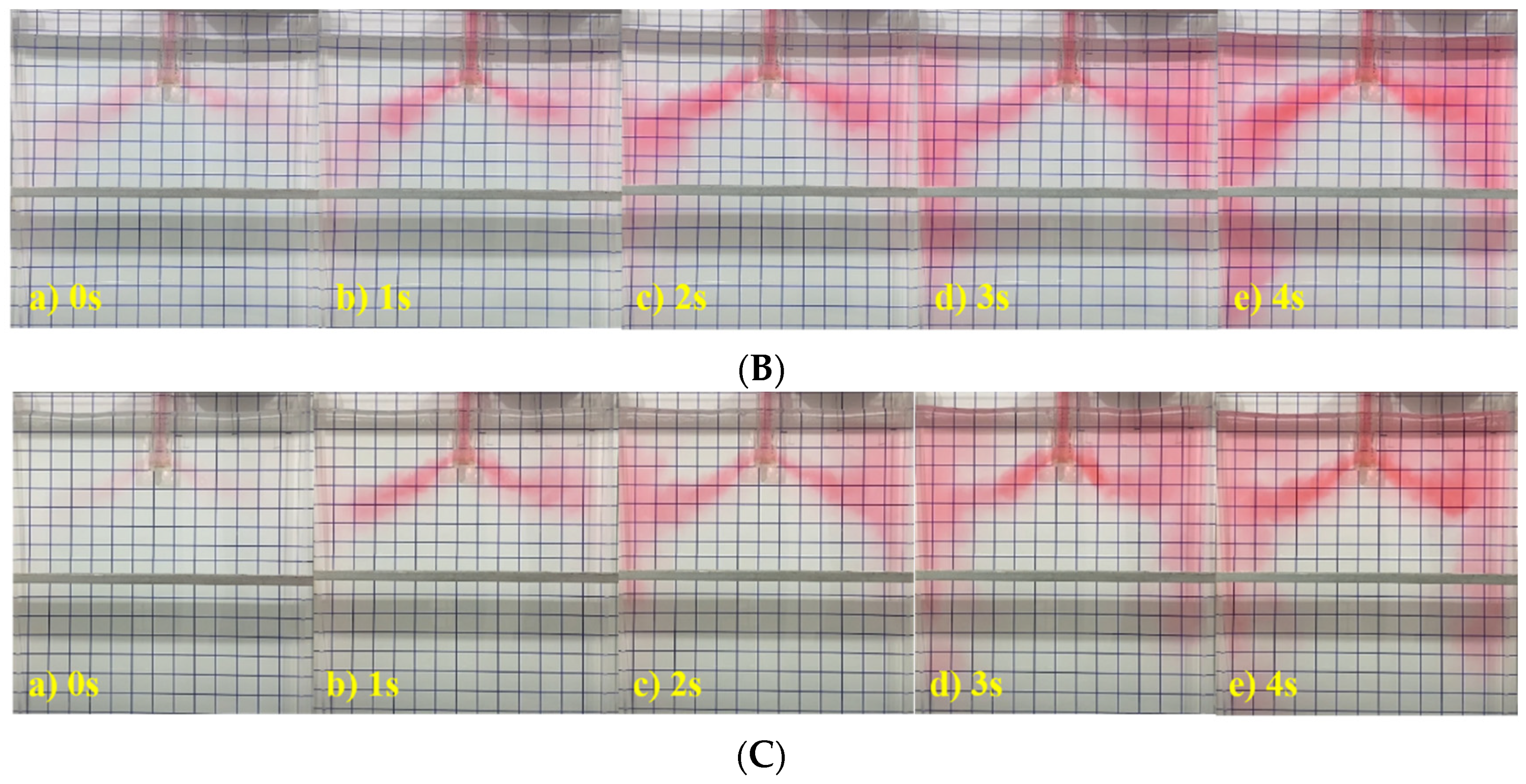
Figure 6.
Velocity distribution of top surface at 1/4 wide face with different immersion depths and casting speed of 1.5 m/min. (A) Type A SEN; (B) type B SEN.
Figure 6.
Velocity distribution of top surface at 1/4 wide face with different immersion depths and casting speed of 1.5 m/min. (A) Type A SEN; (B) type B SEN.

Figure 7.
Liquid level fluctuation at casting speed of 1.50 m/min. (A) type A SEN; (b) type B SEN.
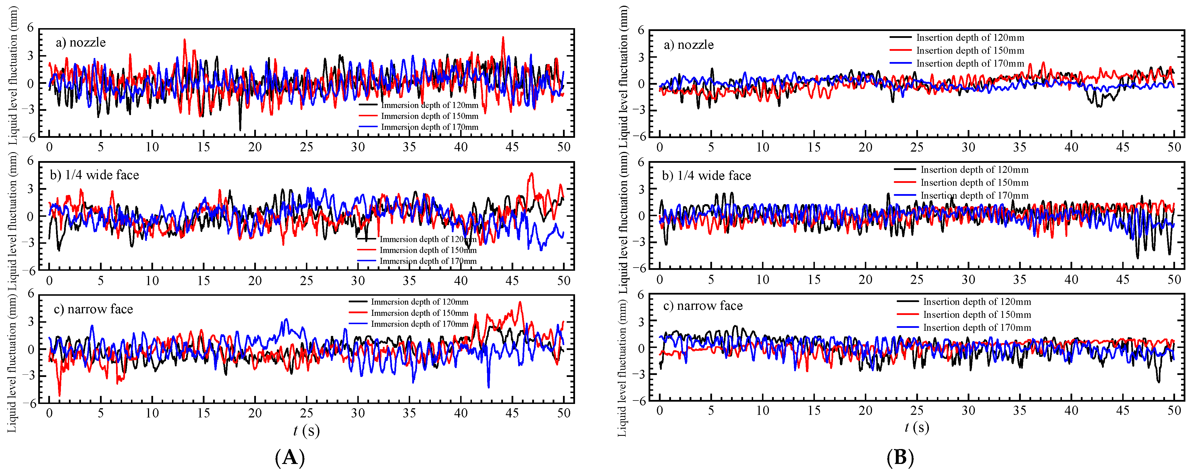
Figure 8.
The proportion of liquid level fluctuation in the range of ±3 mm. (A) type A SEN; (B) type B SEN.
Figure 8.
The proportion of liquid level fluctuation in the range of ±3 mm. (A) type A SEN; (B) type B SEN.

Figure 9.
Oil distribution at different SEN immersion depths at casting speed of 1.50 m/min. (A) Type A SEN; (B) type B SEN.
Figure 9.
Oil distribution at different SEN immersion depths at casting speed of 1.50 m/min. (A) Type A SEN; (B) type B SEN.
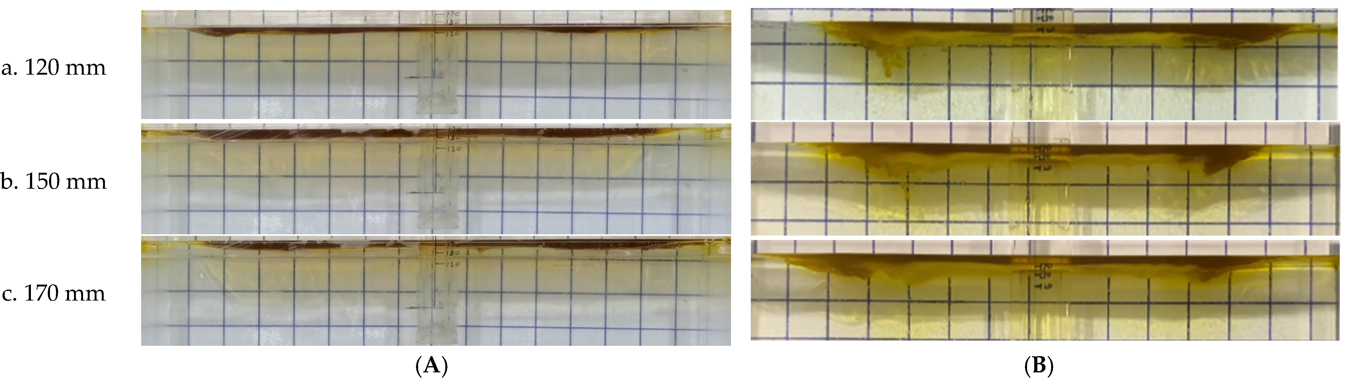
Figure 10.
Distributions of surface velocity, temperature, and shell thickness at the mold outlet at different SEN immersion depths and casting speed of 1.50 m/min. (A) Type A SEN; (B) type B SEN.
Figure 10.
Distributions of surface velocity, temperature, and shell thickness at the mold outlet at different SEN immersion depths and casting speed of 1.50 m/min. (A) Type A SEN; (B) type B SEN.


Table 1.
Dimensions and parameters of prototype and water model using type A and B SENs.
| Parameters | Prototype | Model |
|---|---|---|
| Cross section of mold (mm2) | 170 × 1550 | 170 × 1550 |
| Immersion depth (mm) | 120, 170 | 120, 170 |
| Casting speed (m/min) | 1.5, 1.7 | |
| Flow rate in water model (m3/h) | 26.4, 29.9 |
| Density (kg/m3) | Viscosity (Pa·s) | |
|---|---|---|
| Water | 998 | 0.001 |
| Silicon oil | 955 | 0.033 |
| Liquid steel | 7020 | 0.0067 |
| Slag | 2600 | 0.20 |
| Interfacial tension between liquid steel and slag (N/m) | 1.15 | |
Table 3.
Property parameters of liquid steel and heat transfer conditions.
| Parameter | Value |
|---|---|
| Density (kg/m3) | 7020 |
| Viscosity (Pa·s) | 0.0062 |
| Specific heat (J/kg/K) | 760 |
| Thermal conductivity (W/m/K) | 31 |
| Latent heat (J/kg) | 272,000 |
| Solidus temperature (K) | 1748 |
| Liquidus temperature (K) | 1791 |
| Heat flux at the narrow face of the mold (kW/m2) | −1500 |
| Heat flux at the wide face of the mold (kW/m2) | −1600 |
Disclaimer/Publisher’s Note: The statements, opinions and data contained in all publications are solely those of the individual author(s) and contributor(s) and not of MDPI and/or the editor(s). MDPI and/or the editor(s) disclaim responsibility for any injury to people or property resulting from any ideas, methods, instructions or products referred to in the content. |
© 2024 by the authors. Licensee MDPI, Basel, Switzerland. This article is an open access article distributed under the terms and conditions of the Creative Commons Attribution (CC BY) license (https://creativecommons.org/licenses/by/4.0/).
Share and Cite
MDPI and ACS Style
Zhen, X.; Peng, S.; Zhang, J. Influence of Submerged Entry Nozzles on Fluid Flow, Slag Entrainment, and Solidification in Slab Continuous Casting. Metals 2024, 14, 349. https://doi.org/10.3390/met14030349
AMA Style
Zhen X, Peng S, Zhang J. Influence of Submerged Entry Nozzles on Fluid Flow, Slag Entrainment, and Solidification in Slab Continuous Casting. Metals. 2024; 14(3):349. https://doi.org/10.3390/met14030349
Chicago/Turabian StyleZhen, Xingang, Shiheng Peng, and Jiongming Zhang. 2024. "Influence of Submerged Entry Nozzles on Fluid Flow, Slag Entrainment, and Solidification in Slab Continuous Casting" Metals 14, no. 3: 349. https://doi.org/10.3390/met14030349
Note that from the first issue of 2016, this journal uses article numbers instead of page numbers. See further details here.