

Morphological Evolution of Single-Core Multi-Strand Wires during Ultrasonic Metal Welding

Chair of Composites and Material Compounds, Institute of Materials Science and Engineering, Chemnitz University of Technology, 09125 Chemnitz, Germany
*
Author to whom correspondence should be addressed.
Metals 2024, 14(3), 362; https://doi.org/10.3390/met14030362
Submission received: 6 February 2024
/
Revised: 7 March 2024
/
Accepted: 19 March 2024
/
Published: 20 March 2024
(This article belongs to the Special Issue Ultrasonic Welding: Joining of Metals and Multi-Material Structures by Power Ultrasonics)
Abstract
:Ultrasonic metal welding (USMW) finds widespread utilization in automotive industries, where it is used for connecting the wire harness of the vehicle, consisting of stranded wires, to the terminals. However, the behavior of the strands during the compaction process is still understudied and often overlooked. Therefore, this work focuses on the investigation of the wire compaction behavior from a morphological point of view. A newly developed method for investigating cross-sections of such joints is introduced, facilitating area quantification of the strands for a microscale examination of compaction variations for every single strand as a function of welding time. It is shown that the deformation in the wire is not homogenous throughout the wire cross-section; instead, the formation of distinct zones is observed. Three distinct regimes dominating the welding process were observed: (i) linear reduction in nugget height with primary compaction of the nugget and sealing of the interstitial spaces between the strands for weld times from 0 s up to 1.3 s; (ii) accelerated loss of nugget height due to strong plastic deformation of the strands for weld times between 1.3 s and 1.7 s; and (iii) comprehensive welding of the individual strands and strong loss of nugget height. Furthermore, it was demonstrated that the deformation of the wire during the USMW process originates in the coupling area of the horn and the wire and not in the interface of the wire and the terminal. Therefore, it can be assumed that the temperature of the interface between the horn and the wire must be significantly higher than that of the interface between the wire and the terminal. The presented approach and new insights into the behavior of ultrasonically welded joints of stranded wires and terminals provide guidance for improving the welding process.
1. Introduction
Ultrasonic metal welding (USMW) is a solid-state process wherein two or more workpieces are joined through frictional heat and severe plastic deformation. This versatile technology is suitable for welding various materials, including sheets, wires, or foils, with both similar or dissimilar joints. USMW has several advantages over conventional fusion welding methods, such as environmental friendliness, energy efficiency, high production rates, and the possibility of multiple layers of sheets and foils or wire strands joining in a single operation [1,2,3]. Widely applied in demanding electrical and electronic applications, USMW plays a crucial role in automotive body construction, lithium-ion battery assembly, and electronic packaging [4].
As the industry increasingly prioritizes energy-efficient manufacturing and applications, lightweight materials in the automotive and aviation industries have become the most efficient way to reduce environmental pollution and improve fuel efficiency [5]. Notably, a reduction of 100 kg in vehicle weight translates to a decrease in fuel consumption by 0.6 L per 100 km and a reduction of 500 g of CO2 emissions per 100 km [6]. In the context of wiring harnesses, the substitution of copper wires with aluminum serves dual purposes—lowering costs and minimizing fuel consumption.
For such reasons, a reliable joining technique is essential to ensure a robust mechanical and electrical connection between Al and Cu [7]. This raises unique challenges for conventional joining processes due to their distinct chemical and mechanical properties. Issues include disparate melting temperatures, preventing the formation of a common melt pool, and the high affinity between materials above 120 °C, leading to the development of brittle intermetallic phases. These challenges are particularly pertinent in electrical contacts, where intermetallic phases can adversely affect mechanical strength and electrical resistance [8]. USMW emerges as a pivotal technique for dissimilar metal joining in automotive applications. It is more suitable for welding dissimilar highly conductive materials, whereas several challenges, such as large differences in melting temperature and reactions between dissimilar metals, limit conventional fusion welding techniques.
During the USMW process, the welding pressure facilitates the transmission of vibration energy from the horn to the workpiece interface. This transfer leads to plastic deformation and the incremental development of microjoints. As the welding process advances, these microjoints progressively extend to the welding interface, ultimately achieving full bonding, resulting in atomic diffusion across the interface. The main parameters of USMW are vibration amplitude, welding pressure, and welding time or energy. These main process parameters are used to control the welding process, and the selection of their optimal combination ensures high and stable welding quality [9]. During the actual operation of wires, the microjoints as well as the welded surface undergo different loading conditions. Thus, the welds should be resistant to crash impact, vibration, and fatigue, as well as be able to maintain a robust electrical connection. While USMW is standardized for certain applications, the joint formation and the influences on the welding process are not yet fully understood, and the welding process is prone to influence from a large number of variables, which lead to fluctuating joint quality and process reliability [10]. Thus far, few studies have provided insights into the bonding mechanism of Al–Cu ultrasonic welding, and further understanding of the joining process between these two most commonly used metals in wiring harness applications is necessary.
Dhara and Das [11] conducted an analysis of both macroscopic and microscopic structures in various Al–Cu joint welds. The study revealed that the superior effectiveness of ultrasonic welding can be attributed to the mixing of materials at the interface, the presence of wavy material flow, and the formation of microbonds at the interface. In a systematic study, Liu et al. [12] delved into the bonding mechanism of the Cu–Al high-power ultrasonic welding interface and explored the formation mechanism of interfacial metal compounds. The investigation revealed that under the influence of welding pressure and ultrasonic vibration, the grain size of pure copper along the welding interface remained relatively unchanged. Conversely, the microstructures of aluminum alloy underwent a transformation from elongated grain sizes to equidistant grain spacing, characterized by properties where each atom is positioned intermediate to its nearest neighbors. Additionally, the presence of intermetallic compounds in the joining zone is still a point of research. The crystal lattice defect of copper exhibits a notably faster diffusion rate through the aluminum matrix at the weld interface. This phenomenon leads to the encapsulation of copper atoms and an excess of aluminum atoms, ultimately causing the formation of the single-metal compound CuAl2 during the welding process [12]. Similar observations were made by Zhao et al. [13] and Wu et al. [14], who determined the intermetallic compounds of Cu9Al4, but on the contrary, no intermetallic compounds were observed by Balasundaram et al. [15]. Additional challenges arise due to the development of passivation layers on the Cu and Al surfaces when exposed to oxygen as well as differences in the surface conditions of the joining partners [16]. These instabilities reduce the contact area of the pure metals in the welding area, subsequently elevating contact resistance. The consequence is a decrease in mechanical properties and current carrying capacity.
Descriptions in the literature of the joining process and bonding mechanisms of ultrasonic metal welding (USMW) often focus on sheet-to-sheet joints [17,18,19,20,21,22]. This is partly due to historical reasons, as sheet-to-sheet joints have represented the most common application for USMW for a long time [23,24,25,26,27,28,29,30]. Additionally, categorizing the joining partners into distinct “upper” and “lower” partners simplifies the explanation of the joining process. With the increasing establishment of electromobility and the substitution of copper with aluminum wires in automotive, aerospace, train, and shipbuilding industries, strand-to-terminal connections are gaining prominence in the industrial application of USMW [31].
While the joining process and bonding mechanisms in the USMW of stranded wires to terminals are fundamentally comparable to those of sheet-to-sheet joints, the complexity of the process is significantly increased when utilizing these joining partners [32]. The wire strand, serving as the upper joining partner, now constitutes a component composed of multiple individual strands, numbering up to 3200. Due to their flexibility, these individual strands can execute relative movements not only towards the terminal but also among themselves during the joining process. The wire strand can thus be considered as an agglomeration of multiple upper joining partners, randomly arranged in space depending on the strand lay.
While the individual strands exhibit a certain cohesion due to the insulation material and their twisting before the joining process, repositioning effects occur during the USMW process due to the power ultrasound [33,34]. Another peculiarity of the USMW process for stranded wires and terminals is the application of pre-pressure by the welding system before the actual USMW process starts [35,36]. This pre-pressure leads to the pre-compaction of the wire bundle, attempting to achieve uniform ultrasound transmission into the joining partners during the USMW process [32]. Due to the confinement of the compaction space by the so-called side shifters and the compaction of individual strands, the wire bundle assumes a rectangular rather than cylindrical cross-section after the USMW process, forming the so-called weld nugget or joining zone.
Furthermore, the USMW process aims not only to establish a connection between a few individual strands and the terminal but also among the strands themselves [16]. This is necessary because only a small proportion of the individual strands are in direct contact with the terminal. Bergmann et al. describe the connection of individual strands to each other [37]. While initially only a point contact between the individual strands exists, the introduction of heat and the occurrence of plastic deformation of the individual strands lead to inter-strand joining. Bergmann et al. also observed three different zones in the weld nugget on cross-sections of welded connections, as shown in Figure 1.
In Zone 3, slight deformations of the cross-sections of the individual strands can be observed, while the individual strands in Zone 2 still exhibit nearly their cylindrical original geometry. Furthermore, defects (gaps) between the individual strands are visible in Zone 2, indicating lower compaction than in Zone 3. Zone 1 is characterized by a high degree of plastic deformation. The individual strands undergo intense deformation in this zone, with such high compaction that the individual strands are visually challenging to separate. Bergmann attributes this to the majority of welding energy being consumed in Zone 1, which is in direct contact with the horn during the USMW process. This is also in good agreement with the observations made by Balz, who showed that only in the early stages of weld formation does the relative motion of the upper and the lower joining partner contribute to the energy input into the weld [25]. According to Balz, slippage between the horn and the upper joining partner leads to the highest energy input. Li et al. investigated the USMW process of aluminum and copper via laser Doppler vibrometry and also observed slippage and stick–slip effects during the process [8].
This study extends beyond the conventional qualitative assessments of cross-sections of these joints by implementing a quantitative analysis on the strand level, based on image recognition techniques. This methodology aims to provide a more detailed understanding of strand behavior and deformation mechanisms during the USMW of wires and terminals. Systematic quantification of strand geometry and variations in the compaction distribution throughout the weld nugget should provide insights that could facilitate the optimization of the USMW process or help in failure analysis in the industrial usage of USMW.
2. Materials and Methods
The USMW experiments were conducted using a welding system MT8000 PowerWheel, manufactured by Telsonic GmbH, Bronschhofen, Switzerland. The welding system exhibits a maximum ultrasonic generator power of 10 kW and a maximum welding force of 8 kN. The utilized horn had a width of 12 mm and a maximum vibration amplitude of 32 µm. It also featured a zig-zag-like profile designed to optimize the coupling of the power ultrasound into the wire. The operating frequency of the horn was set at 20 kHz.
As joining partners, copper terminals made from Cu-ETP and automotive wires composed of the aluminum alloy AA1370A were utilized. The terminals had a length of 50 mm, a width of 22.5 mm, and a thickness of 3 mm, manufactured through waterjet cutting from copper plates, with the longitudinal side of all terminals aligned along the original rolling direction. The wires featured a cross-section of 50 mm2 and conformed to the FLALRY cable type (aluminum automotive wire with reduced insulation wall thickness and polyvinyl chloride insulation). The wires comprised 247 individual strands with maximum diameters of 0.52 mm and were pre-cut to a length of 300 mm. The insulation was removed at a distance of 15 mm from the wire end. Before welding, the terminals were degreased with denatured ethanol and subsequently etched in 10% sulfuric acid to remove oxides. Suitable process parameters were determined beforehand by performing a face-centered central composite design experiment with an optimization target of maximum failure load. The maximum failure load achieved in the design of the experiment was 3.250 N, which was obtained by using a welding pressure of 1.5 bar, an ultrasound trigger at a welding force of 800 N, an ultrasound amplitude of 90% of the maximum amplitude of the horn, and a target ultrasound energy of 3500 J, which led to a weld time of 1.5 s. This set of parameters was also used in these investigations.
For the light microscopic examination of the produced joints, initial pre-cutting was performed using an Accutom-50 (Struers GmbH, Ottensoos, Germany). The samples were then embedded in an epoxy resin-based cold mounting material, EpoThin (Buehler, Uzwil, Switzerland). Initially, the embedded specimens were manually wet-ground on a rotating disc grinder using silicon carbide abrasive papers ranging from P400 to P4000. Subsequent polishing steps involved diamond suspensions with particle sizes ranging from 3 to 1 µm on an automatic polishing machine, Tegramin from Struers. The final polish was accomplished using a chemo-mechanical oxidizing polishing suspension, OP-S (Struers), to remove any embedded diamond particles from the samples. For the etching of the strands, 90 mL of distilled water was brought to a boil with 10 mL of 40% hydrofluoric acid. Subsequently, the solution was saturated with molybdic acid [38]. This etching process was conducted under optical control for 15–30 s, depending on the saturation of the etchant. Light microscopic images were taken with a Neophot 32 (Carl Zeiss Jena GmbH, Jena, Germany).
To assess the compaction ratio, bimodal analyses were conducted on the cross-sections. First, the light microscopic images were segmented using thresholding techniques in the open-source software ImageJ 1.54g (Wayne Rasband and contributors, National Institutes of Health, USA). Subsequently, a measurement area (region of interest, ROI) was defined, utilizing the largest rectangle inscribed within the weld nugget. The compaction ratio rcompaction was then determined by establishing the ratio between the overall number of pixels in the image as well as just white pixels in the image via the following equation:
where SWP stands for the number of white pixels and SAP for the overall number of pixels in the ROI.
rcompaction [%] = 100 × SWP/SAP,
The etching process allowed for the identification of individual wire strands even after the USMW process, enabling quantitative analysis of individual wire cross-sections across the entire weld nugget. Initially, using Photoshop 2024 (Adobe Inc., San José, CA, USA) image processing software and the artificial intelligence-powered (AI) “Quick Selection Tool”, individual wire strands were marked and selectively colored with complementary colors, ensuring that each adjacent wire strand had a different, high-contrast color value. Subsequently, the resulting graphic was imported into Illustrator 2024 (Adobe), a vector graphics software, and the now distinguishable individual wire strands were vectorized using the Image Tracer. A JavaScript was then written to number the generated shapes and, based on the image scale, calculate their areas. Another JavaScript assigned a color gradient to each area measurement and colored the area accordingly.
3. Results and Discussion
To investigate the macroscopic behavior of the weld nugget over time during the USMW process, light microscopic examinations were conducted on weld conditions with welding times incremented from 100 ms to a maximum of 2000 ms. The previously identified optimal parameter set yielded a welding time of 1500 ms. Three samples per weld time increment were investigated, whereas Figure 2 illustrates exemplary weld conditions at (a) 100 ms, (b) 500 ms, (c) 1000 ms, (d) 1500 ms, and (e) 2000 ms welding time.
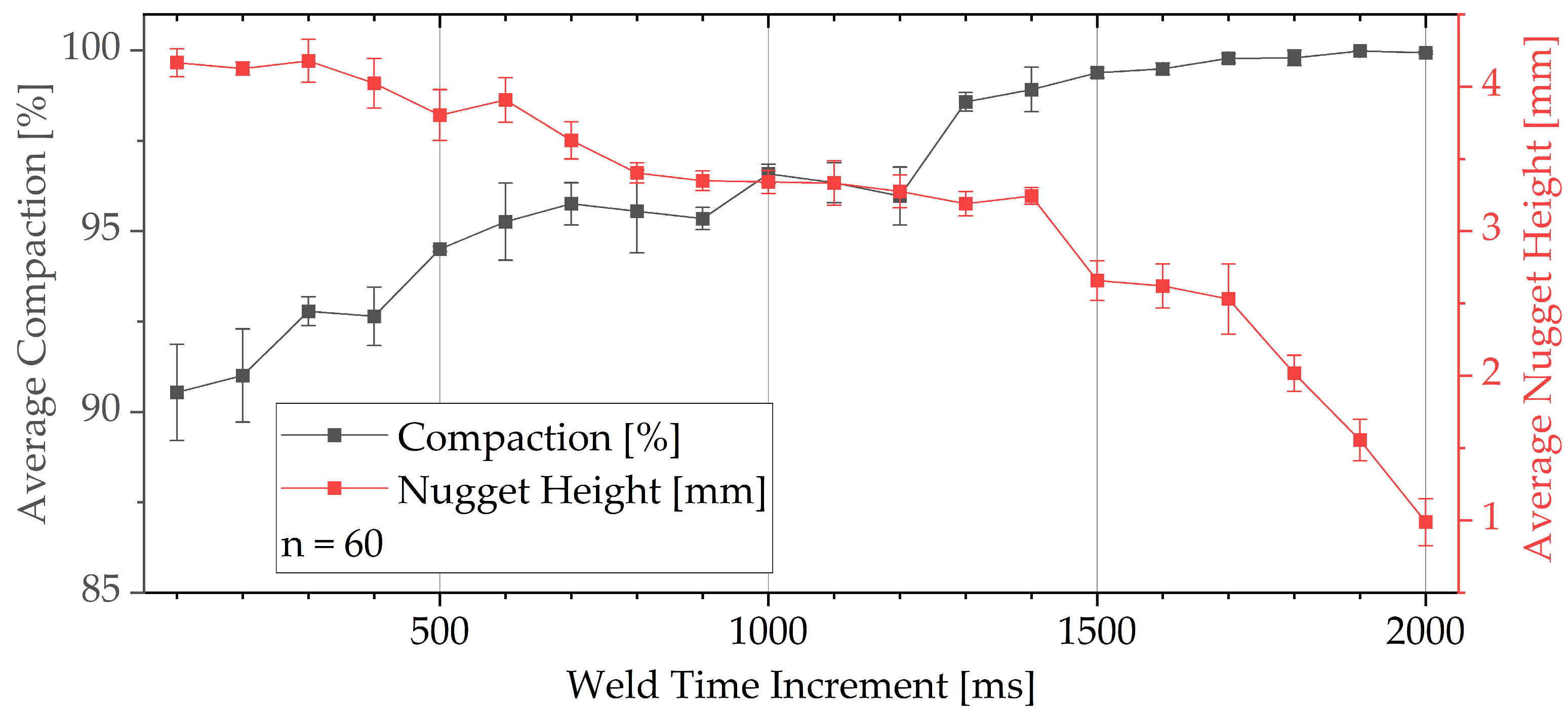
As anticipated, there is a consistent reduction in nugget height with increasing welding time across all time steps. Additionally, a decrease in defects (weld flash) can be observed with prolonged welding time, attributed to the increasing compaction and plastic deformation of the weld nugget. For a more precise evaluation of the defects, the compaction ratio was calculated using bimodal analysis. Furthermore, a determination of the time-dependent nugget height was conducted. The trends of both parameters are depicted in Figure 3.
The compaction of the weld nugget exhibits a linear increase up to a welding time of 1.5 s, after which it shows a degressive behavior up to a welding time of 2 s. As evident in Figure 3, the compaction ratio rises due to the increasing closure of gaps between the strands caused by the deformation of individual wire strands, which approach an ideal honeycomb-like geometry during the welding process. Additionally, from the light microscopic images, it can be observed that the compaction initiates in the horn-proximal region initially, and until a welding time of 1.5 s, there are still visible gaps between the strands in the terminal-proximal area. From this welding time onward, the individual wire strands closest to the terminal undergo sufficient deformation, closing the remaining gaps between the wires, and the compaction ratio approaches a value of 100%. From this behavior, it can be assumed that the highest energy input in the welding zone occurs at the interface of the horn and the horn-proximate strands, which is in good agreement with the observations of Balz, who observed this behavior for sheet-to-sheet USMW joints of copper [25].
The nugget height decreases almost linearly up to a welding time of 1.5 s but then decreases progressively until the maximum welding time of 2 s. This behavior can be attributed to the continuous plasticization of the individual wire strands due to increasing overheating of the weld nugget, which offers no resistance to the horn penetration. With the continued progression of the USMW process, it is anticipated that all aluminum from the strands will be displaced from the joining zone.
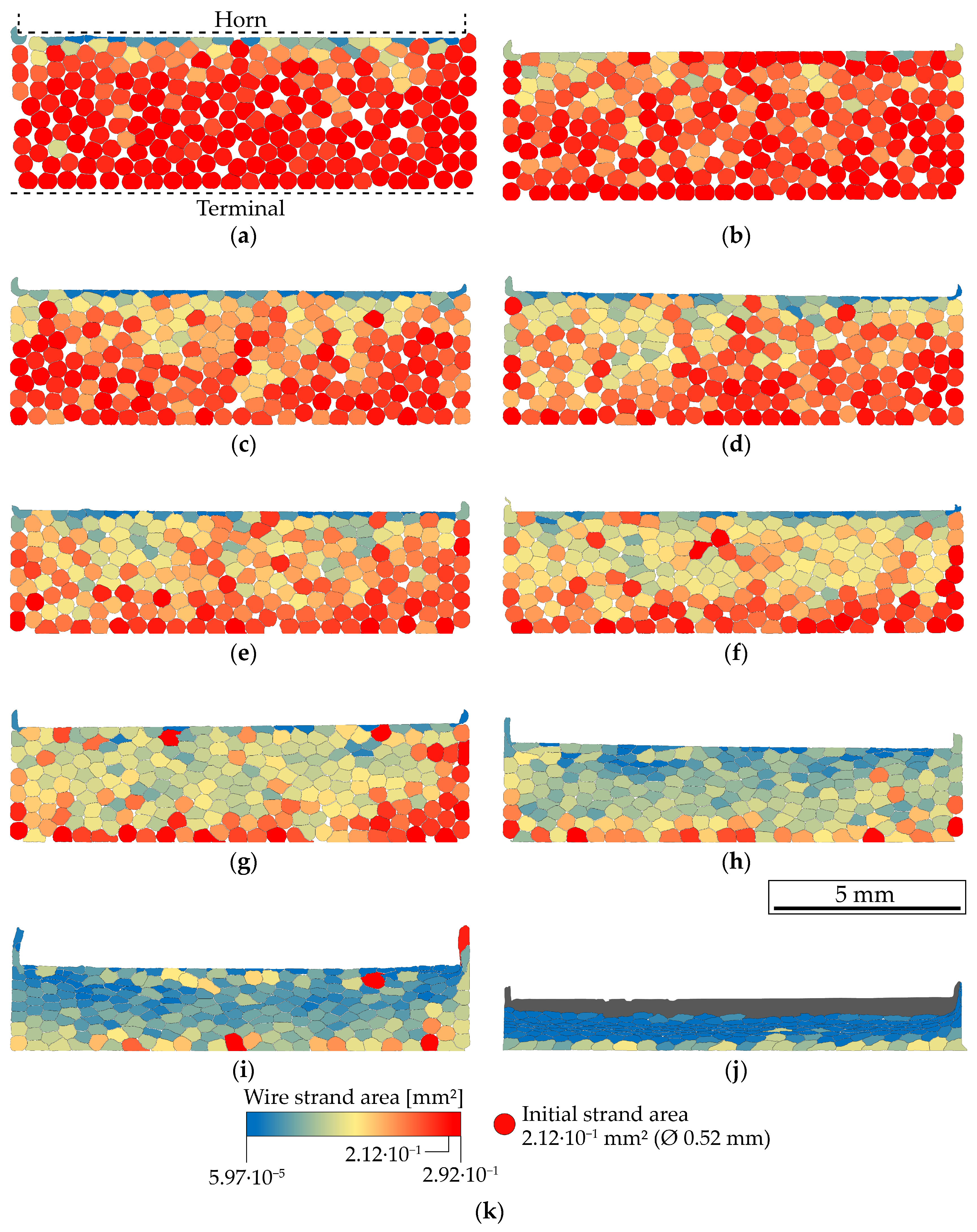
Subsequently, quantification of individual wire strand areas was conducted to assess the development of the joining zone morphology. Figure 4 shows the results and skips, for the sake of clarity, at every second welding time increment.
Quantification of individual wire strand areas reveals that there is no uniform deformation of the individual wire strands within the weld nugget. Instead, distinct local zones with a clear structure emerge during the USMW process. At the beginning of the welding process, a reduction in individual wire strand areas occurs only in the horn-proximal region within the upper two layers of individual wire strands. With increasing welding time, this reduction in the area gradually extends towards the terminal-proximal wire strands. From a welding time of 0.5 s (Figure 4c) onwards, the first significant cross-sectional reductions appear in the terminal-proximal layer of individual wire strands. Up to a welding time of 1.3 s, sealing of the interstitial space between the strands can be observed.
Even at the optimal welding time of 1.5 s (Figure 4h), there is still no homogeneous distribution of individual wire strand cross-sectional areas. The terminal-proximal layer of wire strands still exhibits larger cross-sectional areas, some of which are still close to the initial cross-section. In the horn-proximal region, further significant reductions in cross-sectional areas occur from a welding time of 1.5 s onwards, spreading towards the terminal during the overwelding phase. Starting at a welding time of 1.9 s (Figure 4j), severe deformation of the individual wire strands occurs in the horn-proximal area in such a way that, even after subsequent molybdenum and hydrofluoric acid etching, they cannot be differentiated. The regions where quantification was no longer possible due to this reason were colored grey. Even after reaching the maximum welding time of 2 s, the cross-sectional areas of the terminal-proximal individual wire strands significantly differ from those of the remaining individual wire strands in the weld nugget. The cross-sectional areas of the terminal-proximal wire strands vary throughout the entire welding time between the initial cross-section and the mean cross-section of all other individual wire strand areas. This observation is attributed to the fact that the ongoing joining of most terminal-proximal wire strands to the terminal prevents further cross-sectional reduction. From the observations, it can be deduced that there are three distinct regimes dominating the welding process:
- Linear reduction in nugget height with primary compaction of the nugget and sealing of the interstitial spaces between the strands for weld times from 0 s up to 1.3 s;
- Accelerated loss of nugget height due to strong plastic deformation of the strands for weld times between 1.3 s and 1.7 s;
- Comprehensive welding of the individual strands and strong loss of nugget height.
In contrast to the observations of Bergmann et al., the distribution of deformations throughout the different zones is not Zone 1 > Zone 3 > Zone 2 (from highest to lowest) but instead Zone 1 > Zone 2 > Zone 3 [37].
Figure 5 illustrates the distributions of individual wire strand cross-section areas. Figure 5a presents an exemplary histogram of the distribution of individual wire strand areas for a welding time of 0.5 s.
To examine the distribution of individual wire strand areas in relation to welding time, a kernel smoothing of the histogram was initially performed using a bandwidth estimation according to Scott [39], represented by the dark gray line in Figure 5a. Figure 5b presents the color-coded kernel smoothing curves for welding time increments in a single histogram. For clarity, only every second increment is visualized here as well. As welding time increases, the homogenization of cross-sectional areas diminishes further. At a welding time of 0.1 s, a majority of cross-sectional areas are concentrated around a value of 0.19 mm2. At a welding time of 1.9 s, the cross-sectional areas are distributed across a spectrum of 0.04–0.16 mm2. The peak values progressively decrease with advancing welding time. The investigations reveal that a homogeneous distribution of individual wire strand deformations is not necessary for a successful USMW process. An even distribution of cross-sectional areas at the optimal welding time of 1.5 s, equivalent to a broad distribution function as depicted for such welding time in Figure 5b, resulted in the highest connection strengths according to the design of experiments.
4. Conclusions
This study delves into the morphological evolution of the weld nugget during USMW over varying time intervals (100 ms to 2000 ms). The key findings include a consistent reduction in nugget height and a decrease in the number of defects with prolonged welding time. The compaction of the weld nugget exhibited a linear increase up to 1.5 s, followed by a degressive trend. Notably, compaction initiation occurred in the horn-proximal region and progressed toward the terminal. The demonstrated novel approach for quantification of individual wire strand areas revealed non-uniform deformation patterns, forming distinct local zones. Even at the optimal welding time, a homogeneous distribution of cross-sectional areas was not achieved, emphasizing the complexity of the deformation process. It was observed that the terminal-proximal strands exhibited only low deformation, which could be attributed to the ongoing joining of these strands to the terminal, which prevented further cross-sectional reduction. It was demonstrated that the quantification approach provides new insights into the behavior of ultrasonically welded joints of stranded wires and terminals. Whereas the quantification itself was easily automated through the utilization of JavaScript, the preliminary and manual step of exposing each singular strand via image processing proved to be time-consuming and not feasible for industrial application. However, with the advent of artificial intelligence in image recognition, it can be assumed that this step can be automated too.
Author Contributions
Conceptualization, A.G.; methodology, A.G.; formal analysis, A.G.; investigation, A.G. and D.O.; resources, G.W.; writing—original draft preparation, A.G.; writing—review and editing, A.G., D.O. and G.W.; visualization, A.G.; supervision, G.W. All authors have read and agreed to the published version of the manuscript.
Funding
This research received no external funding.
Data Availability Statement
The raw data supporting the conclusions of this article will be made available by the authors on request.
Acknowledgments
We thankfully acknowledge Marat Rebrin and Paul Seidel for metallographic sample preparation and etching of the samples.
Conflicts of Interest
The authors declare no conflicts of interest.
References
- Li, J.; Rienks, M.; Balle, F. Development of a High-Frequency Test System to Study the Wear of Ultrasonic Welding Tools. Metals 2023, 13, 1935. [Google Scholar] [CrossRef]
- Müller, F.W.; Mirz, C.; Weil, S.; Schiebahn, A.; Corves, B.; Reisgen, U. Weld quality characterization by vibration analysis for ultrasonic metal welding processes. J. Adv. Join. Process. 2023, 8, 100149. [Google Scholar] [CrossRef]
- Meng, Y.; Lu, K.-C.; Dong, Z.; Li, S.; Shao, C. Explainable few-shot learning for online anomaly detection in ultrasonic metal welding with varying configurations. J. Manuf. Process. 2023, 107, 345–355. [Google Scholar] [CrossRef]
- Lin, J.-Y.; Hu, K.-C.; Hsieh, T.-L.; Chu, H.-E. Improved interfacial strength of Ti/Ti ultrasonic welds by introducing α/β/α heterogeneous bonding interface. Scr. Mater. 2023, 237, 115724. [Google Scholar] [CrossRef]
- Li, Y.; Chen, J.; Agrawal, P.; Feng, Z. Microstructure and mechanical properties of ultrasonic spot welding of AA7075-T6 and A380 casting aluminum alloy. J. Manuf. Process. 2024, 110, 126–133. [Google Scholar] [CrossRef]
- Zhang, C.; Li, H.; Liu, Q.; Huang, C.; Zhou, K. Ultrasonic Welding of Aluminum to Steel: A Review. Metals 2023, 13, 29. [Google Scholar] [CrossRef]
- Li, J.; Zillner, J.; Balle, F. In-Depth Evaluation of Ultrasonically Welded Al/Cu Joint: Plastic Deformation, Microstructural Evolution, and Correlation with Mechanical Properties. Materials 2023, 16, 3033. [Google Scholar] [CrossRef]
- Li, J.; Balle, F. In-situ observation of the bond formation process during ultrasonic metal welding of Al/Cu joints using Laser Doppler Vibrometry. J. Manuf. Process. 2023, 106, 1–11. [Google Scholar] [CrossRef]
- Abi Raad, E.; Vorländer, M. Acoustic monitoring of weld strength in ultrasonic metal welding by tracking welding stages. J. Manuf. Process. 2023, 101, 1055–1064. [Google Scholar] [CrossRef]
- Balz, I.; Raad, E.A.; Rosenthal, E.; Lohoff, R.; Schiebahn, A.; Reisgen, U.; Vorländer, M. Process monitoring of ultrasonic metal welding of battery tabs using external sensor data. J. Adv. Join. Process. 2020, 1, 100005. [Google Scholar] [CrossRef]
- Dhara, S.; Das, A. Impact of ultrasonic welding on multi-layered Al–Cu joint for electric vehicle battery applications: A layer-wise microstructural analysis. Mater. Sci. Eng. A 2020, 791, 139795. [Google Scholar] [CrossRef]
- Liu, J.; Cao, B.; Yang, J. Texture and intermetallic compounds of the Cu/Al dissimilar joints by high power ultrasonic welding. J. Manuf. Process. 2022, 76, 34–45. [Google Scholar] [CrossRef]
- Zhao, Y.Y.; Li, D.; Zhang, Y.S. Effect of welding energy on interface zone of Al–Cu ultrasonic welded joint. Sci. Technol. Weld. Join. 2013, 18, 354–360. [Google Scholar] [CrossRef]
- Wu, X.; Liu, T.; Cai, W. Microstructure, welding mechanism, and failure of Al/Cu ultrasonic welds. J. Manuf. Process. 2015, 20, 321–331. [Google Scholar] [CrossRef]
- Balasundaram, R.; Patel, V.K.; Bhole, S.D.; Chen, D.L. Effect of zinc interlayer on ultrasonic spot welded aluminum-to-copper joints. Mater. Sci. Eng. A 2014, 607, 277–286. [Google Scholar] [CrossRef]
- Pöthig, P.; Grätzel, M.; Bergmann, J.P. Influence of different surface conditions on mechanical properties during ultrasonic welding of aluminum wire strands and copper terminals. Weld World 2023, 67, 1427–1436. [Google Scholar] [CrossRef]
- Balle, F.; Huxhold, S.; Emrich, S.; Wagner, G.; Kopnarski, M.; Eifler, D. Influence of Heat Treatments on the Mechanical Properties of Ultrasonic Welded AA 2024/CF-PA66-Joints. Adv. Eng. Mater. 2013, 15, 837–845. [Google Scholar] [CrossRef]
- Bergmann, J.P.; Regensburg, A.; Schürer, R.; Petzoldt, F.; Herb, A. Effect of the interface characteristics on the joint properties and diffusion mechanisms during ultrasonic metal welding of Al/Cu. Weld World 2017, 61, 499–506. [Google Scholar] [CrossRef]
- Patschger, A.; Bliedtner, J.; Bergmann, J.P. Approaches to Increase Process Efficiency in Laser Micro Welding. Phys. Procedia 2013, 41, 592–602. [Google Scholar] [CrossRef]
- Balle, F.; Emrich, S.; Wagner, G.; Eifler, D.; Brodyanski, A.; Kopnarski, M. Improvement of Ultrasonically Welded Aluminum/Carbon Fiber Reinforced Polymer-Joints by Surface Technology and High Resolution Analysis. Adv. Eng. Mater. 2013, 15, 814–820. [Google Scholar] [CrossRef]
- Magin, J.; Balle, F. Solid state joining of aluminum, titanium and their hybrids by ultrasonic torsion welding. Mater. Werkst 2014, 45, 1072–1083. [Google Scholar] [CrossRef]
- Strass, B.; Wagner, G.; Eifler, D. Realization of Al/Mg-Hybrid-Joints by Ultrasound Supported Friction Stir Welding. MSF 2014, 783–786, 1814–1819. [Google Scholar]
- Vries, E.D. Mechanics and Mechanisms of Ultrasonic Metal Welding. Ph.D. Thesis, The Ohio State University, Columbus, OH, USA, 2004. [Google Scholar]
- Wodara, J. Ultraschallfügen und -Trennen; Verl. für Schweißen und Verwandte Verfahren DVS-Verl.: Düsseldorf, Germany, 2004; ISBN 978-3-87155-212-0. [Google Scholar]
- Balz, I. Prozessanalyse der Thermo-Mechanischen Vorgänge Während der Verbindungsbildung beim Metall-Ultraschallschweißen. Ph.D. Thesis, Rheinisch-Westfälische Technische Hochschule Aachen, Aachen, Germany, 2020. [Google Scholar]
- Lu, Y.; Song, H.; Taber, G.A.; Foster, D.R.; Daehn, G.S.; Zhang, W. In-situ measurement of relative motion during ultrasonic spot welding of aluminum alloy using Photonic Doppler Velocimetry. J. Mater. Process. Technol. 2016, 231, 431–440. [Google Scholar] [CrossRef]
- Li, H.; Choi, H.; Ma, C.; Zhao, J.; Jiang, H.; Cai, W.; Abell, J.A.; Li, X. Transient Temperature and Heat Flux Measurement in Ultrasonic Joining of Battery Tabs Using Thin-Film Microsensors. J. Manuf. Sci. Eng. 2013, 135, 523. [Google Scholar] [CrossRef]
- Harthoorn, J.L. Ultrasonic Metal Welding. Ph.D. Thesis, Technische Hogeschool Eindhoven, Eindhoven, The Netherlands, 1978. [Google Scholar]
- Lee, S.; Kim, T.H.; Hu, J.; Cai, W.W.; Abell, J.A.; Li, J. Defining Joint Quality Using Weld Attributes. In Ultrasonic Welding of Lithium-Ion Batteries; Cai, W.W., Ed.; ASME Press: New York, NY, USA, 2017; pp. 15–36. ISBN 9780791861257. [Google Scholar]
- Vlad, M. Ultrasonic Welding of Aluminum: A Practical Study in Consistency, Part Marking and Control Modes; Iowa State University: Ames, IA, USA, 2007. [Google Scholar]
- Wagner, G.; Balle, F.; Eifler, D. Ultrasonic welding of aluminum wires with large cross sections. In Proceedings of the 12th International Conference on Aluminium Alloys, Yokohama, Japan, 5–9 September 2010; The Japan Institute of Light Metals: Tokyo, Japan, 2010; pp. 934–939. [Google Scholar]
- Regensburg, A.; Petzoldt, F.; Schürer, R.; Hellwig, P.; Bergmann, J.P. Effect of local preheating during ultrasonic welding of Al-Cu joints on strand compaction and bond formation. Weld World 2017, 61, 443–451. [Google Scholar] [CrossRef]
- Mostafavi, S.; Bamer, F.; Markert, B. Molecular dynamics simulation of interface atomic diffusion in ultrasonic metal welding. Int. J. Adv. Manuf. Technol. 2022, 118, 2339–2353. [Google Scholar] [CrossRef]
- Raad, E.A.; Balz, I.; Reisgen, U.; Vorländer, M. Investigation of the Applicability of Acoustic Emission and Vibration Analysis to Describe the Thermo-Mechanical Mechanism during Ultrasonic Metal Welding; Universitätsbibliothek der RWTH Aachen: Aachen, Germany, 2019. [Google Scholar]
- Mostafavi, S.; Hesser, D.F.; Markert, B. Detection of terminal oscillation pattern in ultrasonic metal welding. J. Manuf. Process. 2019, 41, 159–167. [Google Scholar] [CrossRef]
- Balle, F.; Huxhold, S.; Wagner, G.; Eifler, D. Damage Monitoring of Ultrasonically Welded Aluminum/CFRP-Joints by Electrical Resistance Measurements. Procedia Eng. 2011, 10, 433–438. [Google Scholar] [CrossRef]
- Bergmann, J.P.; Köhler, T.; Pöthig, P. Ultrasonic welding. In Advanced Joining Processes; Elsevier: Amsterdam, The Netherlands, 2021; pp. 239–267. ISBN 9780128207871. [Google Scholar]
- Petzow, G. Leicht korrigierte Auflage. In Metallographisches, Keramographisches, Plastographisches Ätzen; Gebrüder Borntraeger: Stuttgart, Germany, 2015; Volume 7, ISBN 978-3-443-23019-7. [Google Scholar]
- Härdle, W.; Marron, J.S. Fast and simple scatterplot smoothing. Comput. Stat. Data Anal. 1995, 20, 1–17. [Google Scholar] [CrossRef]
Figure 1.
Distinct morphological zones in the weld nugget according to Bergman et al. (adapted from Ref. [37]).
Figure 1.
Distinct morphological zones in the weld nugget according to Bergman et al. (adapted from Ref. [37]).

Figure 2.
Light microscopic images of cross-sections of joints welded with (a) 100 ms; (b) 500 ms; (c) 1000 ms; (d) 1500 ms; and (e) 2000 ms.
Figure 2.
Light microscopic images of cross-sections of joints welded with (a) 100 ms; (b) 500 ms; (c) 1000 ms; (d) 1500 ms; and (e) 2000 ms.

Figure 3.
Average compaction and average nugget height as a function of welding time.

Figure 4.
Wire strand area for distinct welding times for (a) 100 ms; (b) 300 ms; (c) 500 ms; (d) 700 ms; (e) 900 ms; (f) 1100 ms; (g) 1300 ms; (h) 1500 ms; (i) 1700 ms; (j) 1900 ms; (k) legend.
Figure 4.
Wire strand area for distinct welding times for (a) 100 ms; (b) 300 ms; (c) 500 ms; (d) 700 ms; (e) 900 ms; (f) 1100 ms; (g) 1300 ms; (h) 1500 ms; (i) 1700 ms; (j) 1900 ms; (k) legend.

Figure 5.
Wire strand distribution for (a) a welding time of 500 ms; and (b) all investigated welding times.
Figure 5.
Wire strand distribution for (a) a welding time of 500 ms; and (b) all investigated welding times.

Disclaimer/Publisher’s Note: The statements, opinions and data contained in all publications are solely those of the individual author(s) and contributor(s) and not of MDPI and/or the editor(s). MDPI and/or the editor(s) disclaim responsibility for any injury to people or property resulting from any ideas, methods, instructions or products referred to in the content. |
© 2024 by the authors. Licensee MDPI, Basel, Switzerland. This article is an open access article distributed under the terms and conditions of the Creative Commons Attribution (CC BY) license (https://creativecommons.org/licenses/by/4.0/).
Share and Cite
MDPI and ACS Style
Gester, A.; Ozherelkov, D.; Wagner, G. Morphological Evolution of Single-Core Multi-Strand Wires during Ultrasonic Metal Welding. Metals 2024, 14, 362. https://doi.org/10.3390/met14030362
AMA Style
Gester A, Ozherelkov D, Wagner G. Morphological Evolution of Single-Core Multi-Strand Wires during Ultrasonic Metal Welding. Metals. 2024; 14(3):362. https://doi.org/10.3390/met14030362
Chicago/Turabian StyleGester, Andreas, Dmitrii Ozherelkov, and Guntram Wagner. 2024. "Morphological Evolution of Single-Core Multi-Strand Wires during Ultrasonic Metal Welding" Metals 14, no. 3: 362. https://doi.org/10.3390/met14030362
Note that from the first issue of 2016, this journal uses article numbers instead of page numbers. See further details here.