Article

Effects of Different CaO/Al2O3 Ratios on the Phase Composition and Desulfurization Ability of CaO-Based Desulfurizers in Hot Metal

1
Department of Materials Science and Engineering, National Chung Hsing University, Taichung City 402202, Taiwan
2
Academy of Circular Economy, National Chung Hsing University, Taichung City 402202, Taiwan
3
China Steel Corporation, Kaohsiung City 812010, Taiwan
*
Author to whom correspondence should be addressed.
Metals 2024, 14(3), 363; https://doi.org/10.3390/met14030363
Submission received: 17 February 2024 / Revised: 15 March 2024 / Accepted: 18 March 2024 / Published: 20 March 2024

Abstract

:
In response to the development of low-carbon smelting technology, reducing the use of fluor-containing materials in desulfurizers is an important research topic. The development of new-generation KR (Kambara Reactor) desulfurizers is shifting towards a higher Al2O3 content rather than CaF2, yet there is currently an absence of thorough and comprehensive mechanisms for desulfurization. Consequently, this research provides an extensive comparison using a specially constructed small-scale KR desulfurization hot model test, alongside FactSage simulation and SEM analysis (of desulfurization process). The findings indicate that at 1400 °C, for the desulfurization of molten iron, the capacity for desulfurization initially increases and then diminishes as the Al2O3 content in the KR desulfurizer rises. With Al2O3 content in the desulfurizer below 22 wt.%, the phase composition predominantly consists of C3A, employing a solid(slag)–liquid(metal) diffusion method for desulfurization. The optimal desulfurization capacity (Ls: 64.1) is observed when the Al2O3 content is 15 wt.%, attributed to the simultaneous presence of CaO particle precipitation and C3A. However, as the Al2O3 content reaches 20 wt.%, all the oversaturated CaO integrates into C3A, leading to a reduction in Ls from 64.1 to 10.7, thereby diminishing the desulfurization capacity by approximately sixfold. When Al2O3 exceeds 22 wt.%, the phase composition transitions from the C3A to C12A7 phase, and the desulfurization approach shifts from solid(slag)–liquid(metal) to liquid(slag)–liquid(metal) diffusion, with Ls decreasing to 23.4. This reduction is due to C12A7’s lower sulfur capacity compared to C3A and the absence of saturated CaO particle precipitation. Therefore, for Al2O3 to effectively replace fluorite in KR desulfurizers, a higher presence of C3A phases and CaO particle precipitation are essential. The desulfurizer must contain over 65 wt.% CaO and maintain Al2O3 levels at 10~16.2 wt.%.

1. Introduction

Reducing the sulfur content in iron and steel has always been a major issue in the iron and steel metallurgy industry. After the blast furnace process, hot metal desulfurization can be employed using a mechanical stirring system named KR (Kambara Reactor); a lime-based desulfurizer is primarily employed [1,2,3]. However, the high melting point of lime-based desulfurizers and the operating temperature of the KR mechanical stirring desulfurization, approximately 1400 °C, pose certain challenges. When iron is molten, silicon (Si) is oxidized to form silicon dioxide (SiO2), which reacts with calcium oxide (CaO) to produce calcium silicate (Ca₂SiO₄). Researchers such as S. Lee et al. [4] and Mitsuo et al. [5] noted the formation of a dense calcium silicate layer on the surface of solid calcium oxide, which impedes the diffusion of sulfur and reduces desulfurization efficiency. Kawai et al. [6] pointed out that the limited flow rate of sulfur in the solid phase underscores the importance of increasing the contact area with molten iron. To accomplish this, the use of flux is necessary to lower the melting point of CaO and improve desulfurization efficiency.
To decrease the melting point of lime and enhance its solubility, calcium fluoride (CaF2) is commonly added [7,8]. However, this poses environmental, refractory, and health hazards [9,10], leading to strict regulations on its use [11]. Therefore, it is critical to seek alternative cosolvents to replace CaF2. Presently, a number of researchers [12,13,14,15,16,17] have explored desulfurizers based on CaO. Pezzin et al. [12] investigated the effects of the liquid and solid phases of CaO–Al2O3 top slag on the efficiency of steel desulfurization, finding that CaO in the liquid slag remained saturated. However, this study was primarily focused on refining at 1600 °C and did not address the desulfurization of hot metal KR at 1400 °C. Y. Yang et al. [13] utilized aluminum dross to produce calcium aluminate as a desulfurizer, examining the effects of sodium oxide (Na2O), SiO2, and titanium dioxide (TiO2) on the desulfurization of hot metal at 1400 °C. The best desulfurization effect was achieved when Na2O constituted 10% of the desulfurizer. Nonetheless, this study adjusted the ratio of CaO to Al2O3 in the desulfurizer to near unity (C/A = 1) and did not examine the impact of Al2O3 content on desulfurization. Yajima et al. [14] demonstrated that adding Al2O3 to the CaO-SiO2-FeOx slag system expanded the liquid phase region when the oxygen partial pressure was 1.8 × 10⁻³ Pa at 1573 K. Takahashi et al. [15] used refining slags, such as CaO-SiO2 and CaO-Al2O3, as fluxes in KR desulfurization tests. By directly substituting 100% refining slag with CaO, they observed a significant reduction in desulfurization capability, indicating that the CaO present in refining slag is insufficient and can only act as a flux. Additionally, the desulfurization capability of CaO combined with CaO-Al2O3 refining slag surpassed that of CaO and CaO-SiO2 refining slag, suggesting that the addition of Al2O3 to CaO-based desulfurizers can improve desulfurization efficiency. Tanaka et al. [16] carried out desulfurization experiments using CaO and 52.7CaO-35Al2O3-7.4SiO2-4.9MgO as a KR desulfurizer, which led to the formation of CaS in the liquid slag between molten iron and solid CaO. Furthermore, the presence of an appropriate amount of solid solution (2.7 at.%) in the calcium aluminate phase was shown to be crucial for desulfurization in the KR desulfurizer. Oktay and Fruehan [17] performed KR desulfurization tests on various compositions of molten iron, such as Fe-Csat-S, Fe-Csat-S-Si, Fe-Csat-S-Zr, and Fe-Csat-S-Si-Al. The results confirmed that the desulfurization capability followed the order Fe-Csat-S-Si-Al > Fe-Csat-S-Si > Fe-Csat-S-Zr > Fe-Csat-S, highlighting the significant role of SiO2 and Al2O3 in KR desulfurization slag. A comprehensive review of the literature [15,16,17] indicates that the formation of calcium aluminate phases profoundly influences the desulfurization ability of KR desulfurizers.
Calcium aluminate is an inorganic compound sintered with CaO and Al2O3 at high temperature that can be generated from aluminum dross as a source of Al2O3. However, aluminum dross, which is composed of Al2O3, aluminum nitride (AlN), a small amount of aluminum (Al), and a small amount of aluminum carbide (Al4C3), is listed as hazardous waste in the EU, and most of it goes directly to landfills without treatment [18,19]. Aluminum will react with water, resulting in ammonia (NH3), flammable gases (hydrogen (H2), and methane (CH4)) [20,21], thereby causing stinky burning and serious harm to groundwater and ecosystems [22,23,24]. According to the studies of C. Y. Lin, F. H. Lu, and Z. Su et al. [25,26], the AlN in AD will transfer to Al2O3 when the temperature is higher than 1000 °C. Hence, many studies have investigated sintered calcium aluminate from aluminum dross [26,27,28]. Z. Su et al. revealed that a 1.7 molar ratio of Ca/Al roasting for 120 min at 1400 °C under ambient atmosphere would result in high-purity dodecacalcium heptaaluminate (C12A7) [26]. Hu et al. showed that mixing CaO and secondary aluminum dross in a 0.6:1 (mass ratio) solution resulted in premelted calcium aluminate slag after calcinated at 1723 K for 2 h [27]. F. A. López et al. noted that using CaCO3 and aluminum dross as sources for a 1:3 molar ratio of Ca/Al mixture and sintering at 1300 °C would result in two kinds of calcium aluminate, tricalcium aluminate (C3A) and C12A7 [28]. Using aluminum dross in steel melting will benefit two methods. On the one hand, this approach could resolve the aluminum issue. On the other hand, it could replace calcium fluoride. In response to near-zero carbon emissions by 2050, fluorite mining should be reduced, and CO2 emissions from mining should be reduced.
Various types of calcium aluminate phases exist, such as C3A, C12A7, calcium mono-aluminate (CA), calcium dealuminate (CA2), and calcium hexaluminate (CA6) [29,30], some of which can absorb sulfur. According to S. Kim et al. [31], different calcium aluminate phases exhibit different sulfur capacities, with C12A7 and C3A demonstrating superior performance. However, field studies on the desulfurization capacity of KR stirred at 1400 °C for different CaO/Al2O
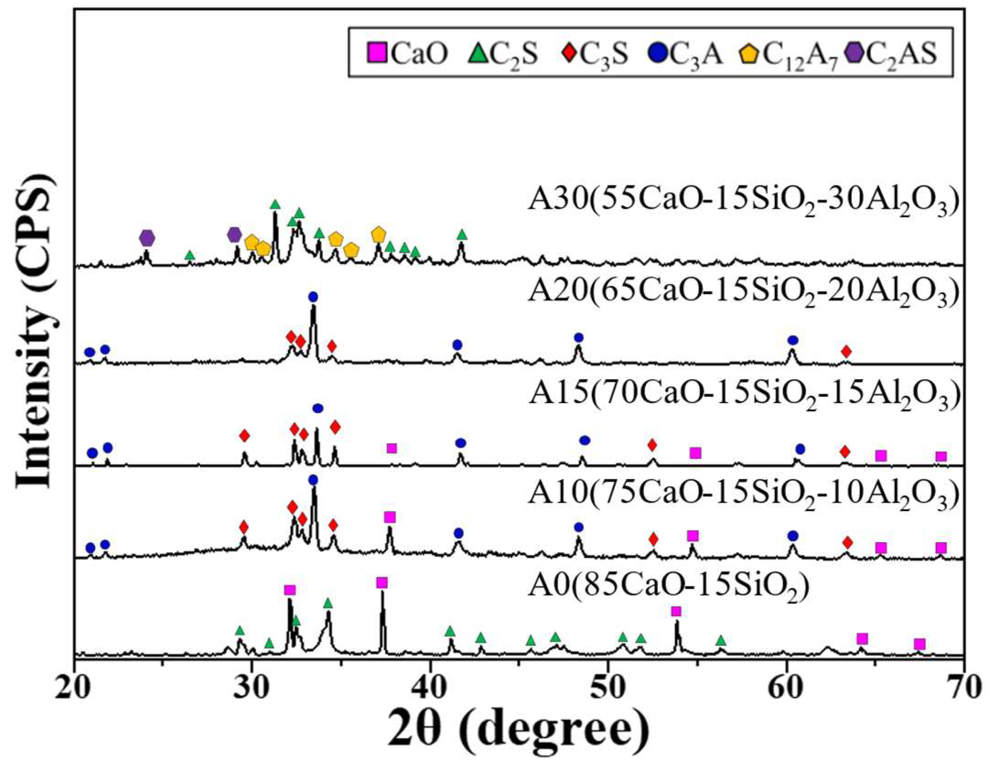
3 ratios and calcium aluminate phase types are lacking. There-fore, this study primarily investigated the phase changes in the Al2O3 in desulfurization slag during mechanical stirring desulfurization with KR without the addition of CaF2. Furthermore, the desulfurization abilities of different CaO/Al2O3 ratios and calcium aluminate phases were compared.

2. Materials and Methods

2.1. Production of the Desulfurization Agent

For this experiment, desulfurizers were formulated with varying ratios of CaO/Al2O3, while maintaining a fixed SiO2 content of 15 wt.%. This choice was made due to the tendency of Si to migrate into the slag through oxidation during the desulfurization process in steel plants. Table 1 presents the chemical composition of the desulfurizers. The code name A represents Al2O3, and the number represents the weight percentage of Al2O3.
The FactSage thermodynamics software (database: FactPS and FToxid, version 7.3, Thermfact Ltd., Quebec, QC, Canada) and the Thermo-Calc software (database: Slag 3.2, Thermo-Calc 4.0, Themo-Calc Software AB, Stockholm, Sweden) were utilized to determine the phase composition of the slag samples. Reagent-grade CaO, SiO2, and Al2O3 were employed to produce the slag. A high-frequency induction furnace (FTR-25H) was used to prepare the desulfurizer. The powder was heated to 1600 °C, ensuring complete liquefaction and thorough mixing before pouring the sample into the air for cooling. The chemical compositions of the slags were analyzed using a WDXRF (Wavelength-dispersive X-ray Fluorescence Spectrometer, Rigaku supermini 200, Rigaku, Tokyo, Japan). To ensure uniformity of the premelted phase composition of the desulfurizer, a Si-Mo electric resistance furnace (SJ High Technology Company, Taipei, Taiwan) was employed to heat the sample to 1400 °C at a rate of 5 °C per minute, maintaining this temperature for 30 min before furnace cooling. The production of the desulfurizer was completed after the furnace had cooled. The phase composition was analyzed using XRD (Bruker D8 Advance diffractometer, Durham, UK) and compared with the simulation results.

2.2. Desulfurization Test

The desulfurization test was conducted using a laboratory-built small KR mechanical stirring desulfurization high-temperature thermal simulation equipment, as depicted in Figure 1. The viscometer (Brookfield DV IIIRV, AMETEK Brookfield, Middleboro, MA, USA) was used as the stirring device. The heating equipment included an induction furnace (Jia Shing Electricity Construction Co., Kaohsiung, Taiwan). The solid iron (composition shown in Table 2) was kept in the MgO crucible (inside diameter: 90 mm, outside diameter: 100 mm, height: 125 mm, inside depth: 120 mm), and the graphite crucible (inside diameter: 120 mm, outside diameter: 140 mm, height: 140 mm, inside depth: 130 mm) was used as the heating medium. When the solid iron melted and was heated to 1400 °C, we waited 5 min and then measured the temperature every 1 min. We made sure the working temperature was controlled between 1400 °C ± 5 °C. Then, we wrapped 36 g of desulfurizer (particle size: 1–3 mm) in paper and tied it to a thin iron rod. We inserted the desulfurizer through the middle hole of the glass cover and put it into the hot metal. Then, we stirred it at 200 rpm for 30 min. Stirring was paused every 10 min. And, we used a vacuum glass rod to insert it from the middle of the glass cover to sample the hot metal. Throughout the heating and desulfurization process, argon was introduced as a protective gas. The total oxygen level of the hot metal was analyzed using an oxygen/nitrogen/hydrogen analyzer (HORIBA (Kyoto, Japan), EMGA-830AC), and the average value during the desulfurization test was 25 ± 5 ppm. The sulfur content of the molten iron sample and desulfurization slag was analyzed using a carbon and sulfur analyzer (HORIBA, EMIA-920) to compare the sulfur capacity. Furthermore, the sulfur-containing phase in the desulfurization slag was observed using SEM (JSM-IT100, JEOL, Tokyo, Japan) and EDS.

3. Results

3.1. Effect of the CaO/Al2O3 Ratio on the Phase Composition

The phase composition results simulated at 1400 °C using FactSage are shown in Table 3. When the Al2O3 ratio increases from 0 wt.% to 20 wt.%, the solid precipitated CaO decreases from 43 wt.% to 0 wt.% and C3A increases from 0 to 53 wt.%. When the Al2O3 concentration increases to 30 wt.%, a liquid phase appears. The phase composition of the high-frequency furnace premelted desulfurizer was analyzed through XRD (Figure 2) and compared with the FactSage simulation results. A0, A10, A15, and A20 matched the simulation results obtained from FactSage. However, the XRD results for the A30 desulfurizer did not reveal the presence of C3A or CA phases.
Through FactSage simulation of the phase composition of A30 at different temperatures (Figure 3a), the absence of the C12A7 phase was observed, attributed to FactSage’s lack of data for the C12A7 phase [32]. To overcome this limitation, Thermo-Calc simulation was performed to analyze the phase composition of A30 at various temperatures (Figure 3b), which confirmed the presence of C12A7 in the composition of 55CaO-15SiO2–30Al2O3. The simulation results validated the impact of the CaO/Al2O3 ratio on the phase composition. When the desulfurizer comprises only CaO and SiO2, the phase composition is made up of CaO and C2S. With the inclusion of Al2O3 in the range of 10~20%, the predominant phase becomes C3A. As the Al2O3 content increases to 30%, the phase composition transitions to C12A7 and C2AS. According to the CaO-Al2O3-SiO2 phase diagram [33], C12A7 is observed when the Al2O3 content is between 20 wt.% and 40 wt.%, with SiO2 maintained at 15 wt.%. Su et al. demonstrated that a 1.7 molar ratio of Ca/Al yields high purity C12A7 [26], and the Ca/Al molar ratio of A30 is indeed 1.7, thereby confirming the presence of C12A7.

3.2. Comparison of Desulfurization Capacity

Figure 4 illustrates the desulfurization morphology of each sample over various durations (at 1400 °C). For desulfurizers with an Al2O3 content ranging from 0 to 20 wt.%, the desulfurizer remains solid even after 30 min of testing. However, when the Al2O3 content reaches 30 wt.%, the desulfurizer begins to sinter and agglomerate from solid particles after 20 min of testing, eventually becoming molten after 30 min. XRD analysis identified C12A7 as the main phase, with a melting point of 1400 °C for the aforementioned ratio, as depicted in Figure 2. FactSage simulation indicated that a liquid phase starts to form when the Al2O3 content is ≥ 22 wt.% at 1400 °C. Thermo-Calc simulation of the phase composition of A30 showed that the liquid phase emerged at 1350 °C, and the ratio of the liquid phase reached 90 wt.% at 1400 °C, as presented in Figure 3b. As a result, an increase in the ratio of Al2O3 reduces the melting point of the CaO desulfurizer.
The rate of desulfurization and the distribution ratio of sulfur for each set of desulfurizers were determined through the application of Equations (1) and (2), respectively. Equation (1) is utilized for calculating the rate of desulfurization, within which S0 denotes the sulfur content in the molten iron before desulfurization and Sf denotes the sulfur content in the molten iron following desulfurization. Calculation of the desulfurization rate is achieved via the subtraction of the sulfur content after desulfurization from the initial sulfur content. Equation (2) represents the sulfur distribution ratio calculation, where Sslag represents the sulfur content in the slag and Ssteel represents the sulfur content in the molten iron. The ratio of the sulfur content in the desulfurization slag to the sulfur content in the molten iron is calculated. The results of these calculations are illustrated in Figure 5.
D e - S   = ( S 0 S f ) S 0 × 100 %
Ls   = S s l a g S s t e e l
Figure 5a depicts the changes in sulfur content in molten iron using different desulfurizers over time. The data show that A0 resulted in a decrease in sulfur content of only 0.00089 wt.%, primarily due to the obstruction of sulfur diffusion into calcium oxide by calcium silicate, thus, diminishing the efficiency of desulfurization [6]. In contrast, for A10 to A30, the sulfur content decreases significantly. A15 had the greatest decrease in sulfur content, with 0.01 wt.% removed.
Figure 5b presents the sulfur distribution ratio and the desulfurization rate for each group. The desulfurization performance was optimal with A15, achieving a desulfurization rate of 65% and the highest sulfur distribution ratio (Ls) of 64. It was closely followed by the desulfurizer with A10, which showed a desulfurization rate of 57% and an Ls of 55. Although the phase composition of A10, A15, and A20 is predominantly C3A, A20 exhibited a significantly lower desulfurization capacity compared to A10 and A15. This difference is due to the lack of CaO particle precipitation and the failure to achieve saturation in A20. Despite the non-saturation of CaO in A30, its desulfurization rate was higher than that of A20. The key reason for this is the increase in Al2O3 content to 30 wt.%, leading to a change in phase composition from C3A to C12A7. This change results in the formation of a significant sulfur-absorbing liquid phase at 1400 °C, altering the desulfurization mechanism from solid(slag)–liquid(metal) interface diffusion to liquid(slag)–liquid(metal) interface diffusion. Therefore, the desulfurization efficiency of A30 exceeds that of A20.

3.3. Analysis of the Sulfur-Tolerant Phase

Two different calcium aluminates with varying compositions, specifically A15 (C3A) and A30 (C12A7), were studied. These constituents were identified as the sulfur-retaining phase in the desulfurization slag. An examination of the sulfur-retaining phase in the desulfurization slag was conducted using SEM, as illustrated in Figure 6. The image is marked by a dotted line, indicating two distinct areas. EDX analysis was also conducted to determine the demarcation of two distinct regions.
An EDX analysis was performed to determine the presence of sulfur in two distinct areas, thereby identifying the reactive and non-reactive zones. The area to the left of the dotted line represents the unreacted zone, while the right side is considered the reaction zone. The reactive zone of A15 has a thickness of approximately 400 µm. The non-reactive zone, as depicted in Figure 7a, is predominantly composed of gray columnar calcium silicate, calcium aluminate, and CaO particle precipitation. In contrast, the reactive zone, illustrated in Figure 7b, consists of gray spherical particles of calcium silicate and calcium aluminate, with an absence of CaO particle precipitation compared to A15. According to EDS results (Table 4), the calcium aluminate phase within the reactive zone contains an average sulfur content exceeding 0.5 at.%.
For A30, part of the liquid slag covers the undissolved desulfurizer, as shown in Figure 6b, with the liquid layer’s thickness being approximately 120 µm. The difference in thickness between the two reaction zones is 280 µm. A15 is primarily composed of C3A, with a melting point of 1540 °C, indicating that the reaction zone does not melt upon contact with hot metal. Conversely, the main phase of A30 is C12A7, with a melting point of 1400 °C, resulting in a melted reaction zone and a thinner layer upon exposure to hot metal. The unreacted area is mainly characterized by dark gray, thin strips of calcium silicate and calcium aluminate, as seen in Figure 8a. Conversely, the reaction area features gray spherical particles of calcium silicate and calcium aluminate, as shown in Figure 8b. EDS analysis (refer to Table 5) indicates that the sulfur-binding capacity of calcium aluminate in this group is less than that in A15, measuring about 0.1 at.%. This diminished capacity is attributed to the lower content of CaO in the A30 desulfurizer, reducing its ability to incorporate sulfur into the slag and, consequently, its sulfur capacity.
Observation of the sulfur phase in the above desulfurization residue confirm that no CaS or other sulfur compounds were found. From the research of Jeong et al. [34], in the Fe-Csat.-0.01S+CaO-CaF2, Wflux/WHM = 0.04 system at 1400 °C, compared the relationship between CaO(s), Liquid, and CaS(S). CaS is formed when Liquid ≤ 10 wt.% and CaO(s) ≥ 90 wt.%. Santo et al. [35] found that, in the multi-oxide system, CaS is formed when CaO(s) ≥ 67 wt.% and the liquid slag is 10–30 wt.%. Based on the above two references, to form a CaS phase, CaO(s) ≥ 67 wt.% and a liquid phase must exist. In the study, no liquid phase was found in the A10–A20 group. A liquid phase was found in group A30, but the CaO content ≤ 75 wt.% and CaO particle precipitation did not appear. Therefore, CaS did not appear in A10-A30 in this test. In the slag, sulfur forms a solid solution with calcium aluminate. According to the aforementioned EDS analysis, the average sulfur capacities of C3A and C12A7 are 0.54 and 0.11 at.%, respectively.
The C3A phase fraction of desulfurizers with different Al2O3 proportions was simulated through FactSage and compared with the desulfurization experimental results (Figure 9). The simulation results indicate that, when the Al2O3 content is below 16.2 wt.%, the desulfurizer contains saturated CaO particles. As the fraction of the C3A phase increases from 0 wt.% to 39.7 wt.%, there is a corresponding increase in the desulfurization capacity, with Ls rising from 2.2 to 64.1. However, when the Al2O3 content exceeds 16.2 wt.%, the CaO particle precipitation is fully integrated into C3A, resulting in the absence of CaO particles in the desulfurizer. Consequently, Ls decreases from 64.1 to 10.7, diminishing the desulfurization capacity by approximately sixfold. This variation occurs due to two main reasons. The first one is the high-volume sulfur phase. According to the research by Baba et al. [36], C3A possesses a higher sulfur capacity than C12A7, leading to an increase in Ls as the C3A content rises. However, despite A20 having the highest ratio of C3A phase, its Ls does not match that of A10 and A15, pointing to the second factor, which is the saturation of CaO precipitation. FactSage simulation and XRD analysis results reveal the absence of CaO particle precipitation in A20. SEM observations of the calcium aluminate in the A20 reaction layer (Figure 10) and EDS analysis demonstrate the absence of sulfur in the calcium aluminate of A20 (Table 6). This indicates that, whether it is for refining desulfurization at 1600 °C [5] or for molten iron desulfurization at 1400 °C, the presence of saturated CaO precipitation in the desulfurizer is critical for enhancing desulfurization performance. This is essential for improving the capacity to transfer sulfur ions from the molten iron to the sulfur-accepting phase.

3.4. Effect of Composition on Desulfurization Speed

Based on the above discussion, we compared the effects of four different phase compositions of CaO, CaO + C3A, C3A, and Liquid on desulfurization at 1400 °C. By calculating the slope of the comparison of the sulfur content in the hot metal of desulfurizers, the desulfurization speed at different times is found (Figure 11). In the CaO-SiO2-Al2O3 slag system, C3A + CaO and liquid slag have better desulfurization speeds in 0–10 min, with an average of about −0.001 wt.%/min. Although, both have the same desulfurization speed. However, due to the influence of the sulfur capacity of C3A and C12A7, the liquid desulfurization speed is 0.0001 wt.%/min lower than the coexistence of C3A + CaO in the 10–30min interval.
Then, the solid desulfurizer groups were compared, and the results showed that CaO + C3A > C3A > CaO. The CaO group has the worst desulfurization effect due to the influence of C2S. In the C3A group, the desulfurization driving force is insufficient due to the absence of saturated CaO particles. Among them, in the C3A + CaO group, although A10 and A15 have the same desulfurization rate, it can be seen from Figure 9 that A15 Ls is better than A10, mainly affected by the C3A phase ratio. Therefore, it is known from the above that CaO mainly affects the desulfurization driving force of the desulfurization agent, and CaO+C3A has the best desulfurization speed. The C3A phase ratio affects the final desulfurization rate.

3.5. Calcium Aluminate Desulfurization

The desulfurization mechanism of Al2O3, as deduced from the analysis of desulfurization agents, desulfurization tests, FactSage, Thermo-Calc simulations, and observations from SEM and EDS, is categorized into two principal types: solid(slag)–liquid(metal) diffusion and liquid(slag)–liquid(metal) diffusion. For Al2O3 contents below 22 wt.%, the desulfurization process mainly employs the solid(slag)–liquid(metal) diffusion approach. On the other hand, when the Al2O3 content is greater than 22 wt.%, the mechanism transitions to predominantly liquid(slag)–liquid(metal) diffusion. Figure 12a illustrates the desulfurization process for Al2O3 contents under 22 wt.%, showing the operation through the solid(slag)–liquid(metal) diffusion method.
Primarily, the Al2O3 phase with less than 22 wt.% is composed of C3A, C2S, and CaO. The literature establishes that C3A is a phase with the capability to retain sulfur [31]. Saturated CaO precipitates draw sulfur from the molten iron into the slag, where it is stored at the interface between C3A and molten iron. Sulfur primarily exists in the form of ions in the desulfurization slag. As illustrated in Figure 12a, the highest concentration of [S2–] ions is found at the junction between the reaction zone and the hot metal. Comparing the sulfur-containing reaction layer of A15 over 10 min and 30 min (Figure 13), the thickness increases from 120 µm to 400 µm, and the sulfur content in the hot metal decreases from 0.022 wt.% to 0.011 wt.%. With the increase in raw materials and reaction time, the thickness (Rr) of the reaction zone expands progressively. If the sulfur capacity continues to increase, it may lead to further expansion of the reaction zone, explaining the superior desulfurization effects of a 15 wt.% Al2O3 desulfurizer. The schematic representation of desulfurization with more than 20 wt.% Al2O3, shown in Figure 12b, primarily involves a liquid(slag)–liquid(metal) diffusion process, with the phase composition mainly consisting of C12A7, C2S, and C2AS. At 1400 °C, the desulfurizer gradually melts, creating a significant volume of liquid slag. While this enhances the diffusion kinetics of sulfur from molten iron to the desulfurizer, the CaO content being below 65 wt.% prevents CaO saturation. Consequently, the oxygen activity is low, resulting in insufficient desulfurization driving capability and a reduced tendency of sulfur in molten iron to migrate to the slag.
These conclusions can be depicted through a schematic diagram, as demonstrated in Figure 12. The first point of consideration is the change in sulfur concentration at the slag–steel interface. Before desulfurization, sulfide ions are uniformly distributed in the molten iron. Following the addition of the desulfurizer and commencement of the stirring process for desulfurization, sulfur atoms are attracted towards the steel slag interface by the desulfurizer. This attraction capability is primarily determined by the CaO present in the desulfurizer, with desulfurization occurring predominantly through the exchange of sulfur ions with oxygen ions in the molten slag. A higher CaO ratio results in more oxygen ions being released, thereby enhancing the ability to attract sulfur ions and increasing the sulfur ion concentration at the molten iron–desulfurization slag interface. The second point of consideration is the diffusion of sulfur ions at the slag–steel interface, where two modes of displacement, solid(slag)–liquid(metal) diffusion and liquid(slag)–liquid(metal) diffusion, were observed. The formation of liquid slag improves the kinetic conditions for the diffusion of sulfide ions, evident from the comparison between A20 and A30.
The CaO content in A20 surpasses that in A30, and the liquid phase in A30 is approximately 50% at 1400 °C. From the comparison of desulfurization capacities illustrated in Figure 6b, it is evident that liquid slag facilitates an efficient pathway for diffusion. The third factor to consider is the desulfurizer’s capacity to store sulfur. After sulfur ions have permeated the slag layer, a phase with a high sulfur storage capacity is required to sequester these ions. These observations lead to the conclusion that the KR desulfurization mechanism reaches its optimum desulfurization capacity when the CaO content in the desulfurizer is above 65% and when there is an adequate amount of liquid slag present, followed by a phase with a high capacity for sulfur, comprising a significant solid phase.
In the context of KR desulfurization, it is advised to utilize Al2O3 rather than fluorite as the desulfurization agent, as depicted in Figure 14. The initial consideration is the variance in sulfur concentration at the slag–steel interface. Before desulfurization, sulfide ions are uniformly distributed within the molten iron. Upon the addition of the desulfurizer and the commencement of stirring for desulfurization, the sulfur ions are drawn toward the steel slag interface by the desulfurizer. This attraction is predominantly governed by the CaO present in the desulfurizer, with desulfurization occurring mainly through the exchange of sulfur ions in the molten iron for oxygen ions in the desulfurizer. The higher the ratio of CaO, the more oxygen ions that are released, enhancing the attraction of sulfur ions and increasing their concentration at the molten iron–desulfurization slag interface. The second aspect involves the diffusion of sulfur ions at the slag–steel interface. The study observed two modes of displacement: solid(slag)–liquid(metal) diffusion and liquid(slag)–liquid(metal) diffusion. The production of liquid slag improves the kinetic conditions for sulfide ion diffusion, as demonstrated by the comparison between A20 and A30. The CaO content in A20 is higher than in A30, and the liquid phase in A30 constitutes about 50% at 1400 °C. The desulfurization capacity comparison in Figure 6b shows that liquid slag provides an effective diffusion channel. The third aspect is the desulfurizer’s sulfur storage ability. Once sulfur ions have diffused into the slag layer, a phase with high sulfur storage capacity is necessary to hold the sulfur ions. Based on these findings, Al2O3 should replace fluorspar as the KR desulfurization agent for enhanced desulfurization performance. It is crucial to maintain both a high C3A phase and CaO particle precipitation. Consequently, the total CaO content should exceed 65 wt.%, and the Al2O3 content should be maintained between 10 to 16.2 wt.%.

4. Conclusions

During this study, a comparative analysis of five distinct CaO/Al2O3 desulfurizer groups was conducted. FactSage simulations and XRD phase composition analyses were carried out (at 1400 °C), alongside comparisons of desulfurization capabilities through KR desulfurization tests. Furthermore, desulfurization slag was examined using SEM and EDS. From these observations, the following conclusions can be drawn:
  • The composition and phase characteristics of different CaO/Al2O3 KR desulfurizers identified via XRD closely align with the FactSage simulation results, validating the accuracy of the simulation. The phase characteristic shifts from the C3A phase when the Al2O3 content is between 10 and 20 wt.% to the C12A7 phase as the Al2O3 content reaches 30 wt.%.
  • The desulfurization process utilizing solid(slag)–liquid(metal) diffusion indicates that, with an Al2O3 content of 20 wt.%, the Ls is 10.7. However, when the Al2O3 content is reduced to 15 wt.%, CaO particle precipitation occurs alongside it, enhancing the ability to attract sulfur ions from the molten iron to the sulfur-accommodating phase.
  • With an Al2O3 content of 30 wt.%, desulfurization operates through liquid(slag)–liquid(metal) diffusion. The sulfur capacity of C12A7 is found to be lower than that of C3A, averaging about 0.1 at% with an Ls of 23.4.
  • To replace fluorspar with Al2O3 as the KR desulfurizer and achieve effective desulfurization performance, it is essential that the total CaO content exceeds 65 wt.% and the Al2O3 content is maintained within 10~16.2 wt.%. This ensures that the desulfurizer possesses a high C3A phase, a high-capacity sulfur phase, and CaO particle precipitation.

Author Contributions

Conceptualization, J.-M.S., C.-M.L. and H.-J.L.; Formal analysis, J.-M.S., C.-M.L., H.-J.L. and Y.-E.C.; Funding acquisition, W.W.; Investigation J.-M.S. and Y.-E.C.; Methodology, J.-M.S., C.-M.L. and H.-J.L.; Project administration, W.W.; Supervision, W.W.; Validation, C.-M.L. and Y.-E.C.; Writing—original draft, J.-M.S.; Writing—review and editing, J.-M.S., C.-M.L., Y.-E.C. and H.-J.L. All authors have read and agreed to the published version of the manuscript.

Funding

This work was supported by the National Science and Technology Council, Taiwan, under projects numbered NSTC 112-2622-E-005-013, NSTC 112-2622-E-005-014, NSTC 112-2221-E-005-028, and NSTC 112-2622-8-006-020.

Data Availability Statement

The original contributions presented in the study are included in the article, further inquiries can be directed to the corresponding author.

Conflicts of Interest

Author Hui-Jan Lin was employed by the company China Steel Corporation. The remaining authors declare that the research was conducted in the absence of any commercial or financial relationships that could be construed as a potential conflict of interest.

References

  1. Visuri, V.-V.; Vuolio, T.; Haas, T.; Fabritius, T. A review of modeling hot metal desulfurization. Steel Res. Int. 2020, 91, 1900454. [Google Scholar] [CrossRef]
  2. Li, Q.; Ma, S.; Feng, M.; Lei, H.; Zou, Z. Energy efficiency characterization and optimization of mechanical stirring multiphase dispersion processes: Applied to kanbara reactors for hot metal desulfurization. J. Mater. Res. Technol. 2023, 24, 5642–5659. [Google Scholar] [CrossRef]
  3. Wang, R.; Jia, S.; He, Z. Numerical investigation on the effects of impeller structures in hot metal desulfurization processes by mechanical stirring. Metals 2022, 12, 229. [Google Scholar] [CrossRef]
  4. Lee, S.; Min, D.J. A study on the formation mechanism of the interfacial layer between solid CaO and molten iron alloys. Met. Mater. Int. 2019, 25, 248–256. [Google Scholar] [CrossRef]
  5. Mitsuo, T.; Shoji, T.; Hatta, Y.; Ono, H.; Mori, H.; Kai, T. Improvement of desulfurization by addition of aluminum to hot metal in the lime injection process. Trans. Jpn. Inst. Met. 1982, 23, 768–779. [Google Scholar] [CrossRef]
  6. Kawai, Y.; Mori, K.; San-Nomiya, Y. Fundamental study on the rate of desulphurization of pig iron by solid lime. Tetsu-to-Hagane 1975, 61, 29–35. [Google Scholar] [CrossRef]
  7. Niekerk, W.H.V.; Dippenaar, R.J. Thermodynamic aspects of Na2O and CaF2 containing lime-based slags used for the desulphurization of hot-metal. ISIJ Int. 1993, 33, 59–65. [Google Scholar] [CrossRef]
  8. Amini, S.; Brungs, M.; Ostrovski, O. Dissolution of dense lime in molten slags under static conditions. ISIJ Int. 2007, 47, 32–37. [Google Scholar] [CrossRef]
  9. Andersson, E.; Sichen, D. The effect of caf2 in the slag in ladle refining. Steel Res. Int. 2009, 80, 544–551. [Google Scholar] [CrossRef]
  10. Jeong, T.S.; Oh, M.K.; Chung, Y.; Park, J.H. Effect of white mud addition on desulfurization rate of molten steel. Metall. Mater. Trans. B 2021, 52, 3596–3605. [Google Scholar] [CrossRef]
  11. Pak, J.J.; Fruehan, R.J. The effect of na2o on dephosphorization by cao-based steelmaking slags. Metall. Trans. B 1991, 22, 39–46. [Google Scholar] [CrossRef]
  12. Pezzin, R.d.O.; Berger, A.P.L.; Grillo, F.F.; Junca, E.; Furtado, H.S.; Oliveira, J.R.d. Analysis of the influence of the solid and liquid phases on steel desulfurization with slags from the CaO–Al2O3 systems using computational thermodynamics. J. Mater. Res. Technol. 2020, 9, 838–846. [Google Scholar] [CrossRef]
  13. Yang, Y.; Wu, P.; Men, G.; McLean, A. Hot metal desulphurization using waste residues from the aluminum industry. High Temp. Mater. Process. 2012, 31, 519–528. [Google Scholar] [CrossRef]
  14. Yajima, K.; Matsuura, H.; Tsukihashi, F. Effect of simultaneous addition of Al2O3 and MgO on the liquidus of the CaO-SiO2-FeOX system with various oxygen partial pressures at 1573 k. ISIJ Int. 2010, 50, 191–194. [Google Scholar] [CrossRef]
  15. Takahashi, K.; Utagawa, K.; Shibata, H.; Kitamura, S.-y.; Kikuchi, N.; Kishimoto, Y. Influence of solid CaO and liquid slag on hot metal desulfurization. ISIJ Int. 2012, 52, 10–17. [Google Scholar] [CrossRef]
  16. Tanaka, T.; Ogiso, Y.; Ueda, M.; Lee, J. Trial on the application of capillary phenomenon of solid CaO to desulfurization of liquid fe. ISIJ Int. 2010, 50, 1071–1077. [Google Scholar] [CrossRef]
  17. Oktay, E.; Fruehan, R.J. On the hot metal desulfurization. Steel Res. 1995, 66, 93–95. [Google Scholar] [CrossRef]
  18. Hong, J.-p.; Wang, J.; Chen, H.-y.; Sun, B.-d.; Li, J.-j.; Chen, C. Process of aluminum dross recycling and life cycle assessment for Al-Si alloys and brown fused alumina. Trans. Nonferrous Met. Soc. China 2010, 20, 2155–2161. [Google Scholar] [CrossRef]
  19. Srivastava, A.; Meshram, A. A hydrometallurgical perspective of aluminium dross recycling. Mater. Today Proc. 2023. [Google Scholar] [CrossRef]
  20. Hu, K.; Reed, D.; Robshaw, T.J.; Smith, R.M.; Ogden, M.D. Characterisation of aluminium black dross before and after stepwise salt-phase dissolution in non-aqueous solvents. J. Hazard. Mater. 2021, 401, 123351. [Google Scholar] [CrossRef]
  21. Lv, H.; Zhao, H.; Zuo, Z.; Li, R.; Liu, F. A thermodynamic and kinetic study of catalyzed hydrolysis of aluminum nitride in secondary aluminum dross. J. Mater. Res. Technol. 2020, 9, 9735–9745. [Google Scholar] [CrossRef]
  22. Verma, S.K.; Dwivedi, V.K.; Dwivedi, S.P. Utilization of aluminium dross for the development of valuable product—A review. Mater. Today Proc. 2021, 43, 547–550. [Google Scholar] [CrossRef]
  23. Xie, M.; Lv, H.; An, H.; Liu, F.; Zhao, H. Effect of alkali doping on the preparation of calcium aluminate by aluminum dross calcification process. Environ. Technol. Innov. 2023, 32, 103312. [Google Scholar] [CrossRef]
  24. Li, R.; Zhong, J.; Xie, M.; Huang, Z.; Zhao, H.; Liu, F. Quantitative evaluation on aln transformation and volatilization of chlorides and fluorides in pyrometallurgical treatment for aluminum dross. J. Mater. Res. Technol. 2024, 29, 2879–2888. [Google Scholar] [CrossRef]
  25. Lin, C.-Y.; Lu, F.-H. Oxidation behavior of aln films at high temperature under controlled atmosphere. J. Eur. Ceram. Soc. 2008, 28, 691–698. [Google Scholar] [CrossRef]
  26. Su, Z.; Liu, K.; Lin, K.; Liu, S.; Zhang, Y.; Jiang, T. A novel route to denitrify, recover chlorines and prepare premelted refine slag of 12cao·7Al2O3 (C12A7) from secondary aluminum dross (SAD). J. Mater. Res. Technol. 2022, 19, 1203–1216. [Google Scholar] [CrossRef]
  27. Hu, S.; Wang, D.; Hou, D.; Zhao, W.; Li, X.; Qu, T.; Zhu, Q. Research on the preparation parameters and basic properties of premelted calcium aluminate slag prepared from secondary aluminum dross. Materials 2021, 14, 5855. [Google Scholar] [CrossRef]
  28. López, F.A.; Martín, M.I.; Alguacil, F.J.; Sergio Ramírez, M.; González, J.R. Synthesis of calcium aluminates from non-saline aluminum dross. Materials 2019, 12, 1837. [Google Scholar] [CrossRef]
  29. Jerebtsov, D.A.; Mikhailov, G.G. Phase diagram of CaO-Al2O3 system. Ceram. Int. 2001, 27, 25–28. [Google Scholar] [CrossRef]
  30. Darban, S.; Reynaert, C.; Ludwig, M.; Prorok, R.; Jastrzębska, I.; Szczerba, J. Corrosion of alumina-spinel refractory by secondary metallurgical slag using coating corrosion test. Materials 2022, 15, 3425. [Google Scholar] [CrossRef]
  31. Kim, S.-j.; Kageyama, M.; Gao, X.; Ueda, S.; Kitamura, S.-y. Solubility of sulfur in the solid oxide of the calcium-aluminate system. ISIJ Int. 2019, 59, 1752–1755. [Google Scholar] [CrossRef]
  32. Lazou, A.; Kolbeinsen, L.; Safarian, J. Evaluation of calcium aluminate slags and pig irons produced from the smelting-reduction of diasporic bauxite. Materials 2021, 14, 7740. [Google Scholar] [CrossRef] [PubMed]
  33. Shu, Q.; Wang, Y.; Li, J.; Liu, Y.; Li, P.; Chou, K. Effect of Na2O on dissolution rate of alumina in CaO–Al2O3–MgO–SiO2 slag. ISIJ Int. 2015, 55, 2297–2303. [Google Scholar] [CrossRef]
  34. Jeong, B.-K.; Bang, G.-H.; Kang, Y.-B. Role of liquid and solid particles in solid-liquid mixed fluxes on sulfur removal from molten iron under centrifugal stirring by an impeller. Powder Technol. 2022, 396, 1–12. [Google Scholar] [CrossRef]
  35. Do Espírito Santo, E.V.; Soares, S.G.; de Oliveira, H.C.C.; Junca, E.; Grillo, F.F.; de Oliveira, J.R. Influence of industrial wastes and different fluxes on hot metal desulfurization efficiency. JOM 2021, 73, 1909–1918. [Google Scholar] [CrossRef]
  36. Baba, Y.; Gao, X.; Ueda, S.; Kitamura, S. Sulfide capacities of solid oxides in calcium-aluminate systems. ISIJ Int. 2020, 60, 1617–1623. [Google Scholar] [CrossRef]
Figure 1. Schematic diagram of the KR mechanical mixing equipment.
Metals 14 00363 g001
Figure 2. XRD analysis results of desulfurizer.
Metals 14 00363 g002
Figure 3. FactSage (a) and Thermo-Calc (b) simulation of the phase composition of A30 at different temperatures.
Metals 14 00363 g003
Figure 4. Comparison of the appearance of desulfurization slag at different reaction times at 1400 °C.
Metals 14 00363 g004
Figure 5. (a) Comparison of the sulfur content in the hot metal of desulfurizers. (b) Sulfur distribution ratio and desulfurization of each group.
Metals 14 00363 g005
Figure 6. SEM images of A15 (a) and A30 (b) desulfurization slags.
Metals 14 00363 g006
Figure 7. SEM images of the A15 desulfurizer: (a) unreacted zone; (b) reacted zone.
Metals 14 00363 g007
Figure 8. SEM images of the A30 desulfurizer: (a) unreacted zone; (b) reacted zone.
Metals 14 00363 g008
Figure 9. FactSage phase fractionation simulation and the relationship between the sulfur partition ratio.
Metals 14 00363 g009
Figure 10. SEM images of the A15 desulfurizer reaction zone.
Metals 14 00363 g010
Figure 11. Effect of composition on desulfurization speed.
Metals 14 00363 g011
Figure 12. Schematic diagram of the calcium aluminate desulfurization method: (a) Al2O3 < 22 wt.%; (b) Al2O3 > 22 wt.%.
Metals 14 00363 g012
Figure 13. A15 Comparison of reaction zone thickness at different times: (a) 10 min; (b) 30 min.
Metals 14 00363 g013
Figure 14. A schematic diagram of KR desulfurization, which is divided into three steps. (The first is the concentration of oxygen ions in the desulfurizer, the second is the replacement of sulfur ions at the slag–steel interface, and the third is the ability of the desulfurizer to store sulfur.)
Metals 14 00363 g014
Table 1. Composition of the desulfurizers in wt.%.
No.Desulfurizer Composition, wt%
CaOSiO2Al2O3
A08515--
A10751510
A15701515
A20651520
A30551530
Table 2. Composition of the solid iron in wt.%.
FeCSiMnPS
94.974.50.40.250.10.035
Table 3. FactSage simulation and XRD analysis of the desulfurizer phase composition.
No.FactSage(1400)XRD
A043CaO + 57C3SC2S, CaO
A1016.7CaO + 26.3C3A + 57C3SC3S, CaO, C3A
A153.3CaO + 39.7C3A + 57C3SC3S, CaO, C3A
A2053C3A + 30.7C2S + 16.3C3SC2S, C3S, C3A
A3034C2S + 1CA + 65LiqC2S, C12A7, C2AS
Table 4. EDX composition analysis of A15 desulfurization slag.
No.Chemical Composition, at.%Phase
CaSiAlOSMg
1–129.489.940.8358.88-0.87C3S
1–229.072.1715.459.00-0.35Rich (Ca, Al)
2–127.5213.930.3058.21-0.05C2S
2–218.193.8716.3160.790.620.21Rich (Ca, Al)
2–317.404.7013.4563.770.470.21Rich (Ca, Al)
2–443.958.203.2043.42-1.23CaO
Table 5. EDX composition analysis of A30 desulfurization slag.
No.Chemical Composition, at.%Phase
CaSiAlOSMg
1–137.7510.943.1247.09-1.09C3S
1–224.212.3615.5356.67-1.23Rich (Ca, Al)
2–126.9012.351.6458.48-0.62C2S
2–219.412.5319.6456.420.121.88Rich (Ca, Al)
2–319.435.7712.9160.990.100.81Rich (Ca, Al)
Table 6. EDX composition analysis of A20 desulfurization slag.
No.Chemical Composition, at.%Phase
CaSiAlOSMg
1–123.863.2713.8258.87-0.19Rich (Ca, Al)
1–220.851.8814.7962.23-0.25Rich (Ca, Al)
Disclaimer/Publisher’s Note: The statements, opinions and data contained in all publications are solely those of the individual author(s) and contributor(s) and not of MDPI and/or the editor(s). MDPI and/or the editor(s) disclaim responsibility for any injury to people or property resulting from any ideas, methods, instructions or products referred to in the content.

