
Long-Term Oxidation Studies on Porous Stainless Steel 430L Substrate Relevant to Its Application in Metal-Supported SOFC

1
College of Chemical Engineering, Zhejiang University of Technology, No. 18 Chaowang Road, Hangzhou 310014, China
2
Key Laboratory of Advanced Fuel Cells and Electrolyzers, Technology of Zhejiang Province, Ningbo Institute of Materials Technology and Engineering, Chinese Academy of Sciences, Ningbo 315201, China
3
NBTM New Materials Group Co., Ltd., No. 1508, Yinzhou Industrial Park, Ningbo 315100, China
*
Author to whom correspondence should be addressed.
Metals 2024, 14(4), 475; https://doi.org/10.3390/met14040475
Submission received: 18 March 2024
/
Revised: 9 April 2024
/
Accepted: 16 April 2024
/
Published: 18 April 2024
(This article belongs to the Section Metallic Functional Materials)
Abstract
:Metal-supported solid oxide fuel cells (MS-SOFCs) can be used in portable mobile power generators due to their excellent thermal cycling performance, low cost, and strong mechanical strength. The selection and lifetime of the support material are crucial factors that affect the cell’s performance and long-term stability. The oxidizability of porous 430L stainless steel in a dry air atmosphere at 800 °C was systematically studied and reported for up to 1500 h. The aim was to investigate the lifetime of porous stainless steel as a support skeleton in a symmetric MS-SOFC. The substrates were characterized and analyzed using scanning electron microscopy, energy spectroscopy, and X-ray diffractometry after different periods of oxidation. The analysis indicated that the porous substrate’s surface oxides, under dry air conditions, consisted primarily of Fe2O3 and Cr2O3, with small amounts of Fe3O4 and MnCr2O4 spinel. The long-term oxidation process can be divided into two stages with distinct characteristics. However, the oxide flaking phenomenon occurred after 1500 h of exposure. The estimated service life of the stainless steel was consistent with the experimental results, which were around 1500 h. This estimation was based on the measured weight gain and thickness data.
1. Introduction
Solid oxide fuel cell (SOFC) is a promising power generation technology [1,2,3]. It efficiently converts chemical energy into electrical energy and reduces pollutant gas emissions compared to conventional power generation technologies. The optimization and improvement of the SOFC process have led to a decrease in operating temperature, thanks to upgrades in electrolyte and electrode materials. This has expanded the development prospects of metal-supported SOFCs [4,5,6].
In previous studies, Lawrence Berkeley National Laboratory (LBNL) designed a metal-supported symmetric cell with an area of about 5–8 cm2. Symmetric cell structures with a porous metal support, a porous electrolyte skeleton, and a dense electrolyte layer were fabricated by tape casting, laminating, and co-sintering. Anode and cathode materials in symmetrical cells were impregnated with nitrate precursor solutions and then converted to the desired oxide phase by sintering at 600 or 850 °C in air [7,8,9]. Symmetrically structured metal-supported fuel cells have a very robust structure and offer great ease of welding at both ends of the cell. Tucker et al. utilized ScSZ as the electrolyte, Pr6O11 as the cathode catalyst, and SDC-Ni as the anode catalyst. The symmetric cells they prepared achieved peak power densities of 1.56, 2.0, and 2.85 W cm−2 at 700, 750, and 800 °C, respectively. The fuel gas used was H2 humidified with 3% water vapor, and the cathode was exposed to air. Performance is further improved if the cathode is exposed to pure oxygen (2.0 W cm−2 at 700 °C) [10]. In a recent report, Dogdibegovic et al. found that increasing the impregnation cycles from 5 to 10 in a symmetric metal-supported fuel cell with an active area of about 50 cm2, prepared by impregnation of cathode and anode catalysts, resulted in an increase in peak power density from 0.3 W cm−2 to 0.52 W cm−2 at the same temperature [9].
Furthermore, symmetric-structured MS-SOFC can be used as a stationary or mobile power generation unit to provide economic and electrical support to developing countries. VOTO™ is a compact, symmetric MS-SOFC power generation product manufactured by Point Source Power (PSP) with technical support from LBNL Laboratories in the United States and has been widely deployed in selected countries in Africa. VOTO™ is a practical and easy-to-use device that allows for instant power generation using a cooking fire. Although the power generated is only a few watts, it is sufficient for powering LED room reading lamps and charging cell phones [11].
Porous ferrite is currently widely used in MS-SOFC due to its low cost, high mechanical strength, and high thermal stress tolerance [5]. The ferritic 430L alloy has a coefficient of thermal expansion (CTE) that matches the most widely used SOFC electrolyte, YSZ (yttrium stabilized zirconia, CTE430L,YSZ: 10~12 ppm K−1) [12,13,14]. However, a major challenge in using the porous 430L substrate as a symmetrical SOFC support for long-term operation is its significantly larger surface area compared to the dense 430L stainless steel of the same size, which can lead to oxidation of the porous stainless steel skeleton over extended use and trigger cell degradation. However, extended operation at higher temperatures results in the formation of a protective Cr2O3 scale on the substrate surface [15,16,17]. This leads to a depletion of chromium in the substrate and breakaway oxidation as the oxidation exposure time increases. Huczkowski et al. have found that the threshold chromium content of the substrate to maintain its protective effect is approximately 12 wt.% [18,19]. There are many more oxidation studies on dense alloys than the number of corrosion studies on porous ferritic steels [20,21,22,23,24,25].
In this paper, the long-term oxidizability of porous 430L substrates as SOFC supports in symmetric metal-supported fuel cells and electric stacks, as well as in portable applications exposed to an air atmosphere, was investigated. The study investigates whether the porous 430L substrate can be used as a support for an extended period of time by analyzing oxidation products, oxide layer structure, and elemental diffusion. The study aims to estimate the lifespan of porous 430L stainless steel substrate as a carrier for portable power generators under highly oxidizing conditions.
2. Materials and Methods
2.1. Sample Selection and Preparation
The experiment utilized a porous 430L stainless steel substrate that was prepared and supplied by NBTM New Materials Group Co., Ltd. (Ningbo, China), a powder metallurgy company in China. The 430L powder particle size is approximately 325 mesh. The chemical composition analysis shows that the powder has a Cr content of 16.59 wt.%, and the content for the other three major elements are 0.37 wt.%, 0.33 wt.%, 0.044 wt.% for Si, Mn, and C, respectively. Other remaining minor elements such as S and P have a content of 0.007 and 0.023 wt.%, respectively. The substrates were received with a porosity of 20–25% after being sintered at 1200 °C. After oxidation, the porous substrate was divided into three 15 × 15 × 0.6 mm3 samples for weighing. The remaining substrate was cut into smaller sizes for morphological characterization and testing.
2.2. Oxidation Experiment
The study of the oxidation process of stainless steel utilized the discontinuous constant temperature oxidation weight gain method. Several pieces of porous substrate were placed in an alumina crucible and then horizontally placed in a constant temperature atmosphere furnace at 800 °C. The temperature difference between the center-placed area of the atmosphere furnace (crucible length of about 10 cm) was ±8 °C. Data were recorded by weighing the substrate with a precision electronic balance with an accuracy of 0.1 mg (Mettler 104E analytical balance). The samples underwent oxidation at 800 °C in an air atmosphere for an accumulated total time of 24, 50, 200, 300, 950, and 1500 h, and then were removed and weighed. For example, the samples were weighed after 24 h oxidation at 800 °C and cooled down to room temperature, and then heated back to 800 °C and held for another 26 h to give a total accumulated time of 50 h. The procedures were repeated till reaching a total time of 1500 h. To minimize effects from heating and cooling stage and thus more accurately measure the oxidation of the samples without introducing a sharp thermal shock, we used a relatively fast and moderate heating rate of 12 °C min−1 and a cooling rate of 10 °C min−1.
The values for the three larger samples were averaged (mt) and compared to the initial mass (m0) to calculate the percentage change in mass, then the percentage change in mass was calculated using Equation (1), with the weighing error in the experiment approximately 0.3%.
During each stage of temperature rise and fall, inert gas was introduced into the tube furnace. Once the temperature reached 800 °C, dry air was introduced and passed through silica gel particles for drying at a flow rate of approximately 250 mL min−1. The samples were oxidized for varying time periods before the oxidizing atmosphere valves were closed and nitrogen (N2) was introduced to begin cooling down to room temperature. The samples were then weighed. All subsequent operations were performed as described above.
2.3. Characterization
The surface and cross-sectional morphology of the oxidized specimens, as well as the elemental distribution, were observed using a thermal field emission scanning electron microscope (SEM, FEI Quanta FEG-250, FEI, Hillsboro, OR, USA) equipped with an X-ray diffraction energy spectrometer (EDS) and a backscattered electron detector (BSE). The oxide composition and structure of the samples after different times of oxidation exposure were analyzed using an X-ray diffractometer (XRD, D8 ADVANCE DAVINCI, BRUKER, Karlsruhe, Germany). Cross sections of the samples were prepared using epoxy resin, sanded with various grits of sandpaper, and polished with diamond suspension to 0.25 μm. The cross-section structure and morphology of selected samples were further characterized by precisely cutting the samples directly on the surface with a focused ion beam (FIB, Auriga, Carl Zeiss, Oberkochen, Germany).
3. Results and Discussion
3.1. Morphology of Original Porous 430L Substrate
Figure 1 shows the obtained microscopic morphology of the porous alloy surface (Figure 1a,b) and cross-section (Figure 1c,d) at different multiples. Uneven and rough surfaces can be clearly seen on the microscopic surfaces, and the distribution of spherical stainless steel particles was not uniform. The water atomization process results in substrate particles with a spherical shape and a size range of 40–50 μm. After sintering, the particles bond better and exhibit a significant necking phenomenon, which enhances the substrate’s toughness and oxidation resistance. The cross-sectional views depicted in Figure 1c,d demonstrate that the individual spherical stainless steel particles were relatively dense and well-bonded, indicating that this porous stainless steel possesses a certain degree of toughness and oxidation resistance and that there is no excessive contact resistance. The substrate’s porosity is maintained between 20 and 25% after sintering at 1200 °C due to the addition of a pore-forming agent.
3.2. Oxidation Kinetics Analysis
In this study, the specific surface area measurements were inaccurate due to the complex and varied internal pores of the porous substrate, which increased in pore size with scale thickness. Therefore, this paper uses the increase in unit mass to indicate the degree of oxidation of the samples. The oxidation kinetics are shown in Equation (2) [24,26,27,28,29].
where (g) is the weight gain of the sample, (g) is the initial weight of the sample, (h) is the oxidation time. n is 1 and 2, respectively, for the surface reaction rate and ion diffusion rate-controlled steps, and the corresponding oxidation rate, , has a unit of % h−1 and %2 h−1, respectively.
Figure 2a shows the weight gain curve and Figure 2b shows the rate curve of the porous substrate after oxidation in a dry air atmosphere at 800 °C. The weight of the substrate increased gradually during oxidation in air, and the whole process was roughly divided into two phases in accordance with the change in the oxidation rate.
During the first stage, which lasted from 6 to 12 h, the obvious surface reaction took place, i.e., the formation of a dense Cr2O3 scale. This scale slows down the transport of oxygen ions into the substrate and the diffusion of metal cations outward. In the second stage, the reaction rate was mainly controlled by ion diffusion, and at the same time, the oxidation rate decreased from 2.58 × 10⁻² % h−1 in the first stage to 3.66 × 10⁻³ %2 h−1. The oxidation curves follow Wagner’s parabolic law gradually.
As oxidation time increased, the oxide scale thickened and the substrate’s porosity decreased. Eventually, the oxide scale began to peel off, leading to a new oxidation process. This resulted in an increase in substrate resistance, rendering it unsuitable as SOFC support.
3.3. XRD Spectral Analysis
Figure 3 displays the XRD spectra of the porous 430L substrate following oxidation at 800 °C for varying durations. The phase composition of the porous alloy was primarily composed of the α-phase, with minor amounts of Cr2O3 and Fe2O3, as well as trace amounts of MnCr2O4 and Fe3O4 phases. Cr2O3 and Fe2O3 phases exhibit weak peaks on the sample surface after 24 h. XRD cannot completely separate the two phases, and there may be a solid solution or mixed phase of (Fe, Cr)2O3 [24,30]. After 200 h of oxidation, XRD clearly showed diffraction peaks of MnCr2O4 and Fe3O4 phases. After 1500 h of oxidation, a variety of oxides and spinel phases coexisted on the surface of the porous substrate. The types of these substances and the intensity of the peaks increased with oxidation time, indicating a gradual increase in the content of oxides. No peaks of other elemental impurities were detected.
3.4. Micromorphology Analysis
To describe the long-term oxidation behavior of the porous substrate in an air atmosphere, we characterized the substrate and present the data in Figure 4, Figure 5, Figure 6, Figure 7 and Figure 8. Figure 4 displays the microscopic surface morphology after oxidation at 800 °C in air for varying durations. After 24 h of oxidation, the substrate was covered by an oxide scale. Additionally, irregular substances, which were manganese-containing oxides and trace amounts of Si-bearing oxides, grew on the stainless steel particles. These substances were not detected in XRD due to the small amount of Si. As the oxidation time increased, the oxide particles on the substrate surface also increased, resulting in a gradual increase in the oxide scale. This effect was most noticeable after 950 h and 1500 h.
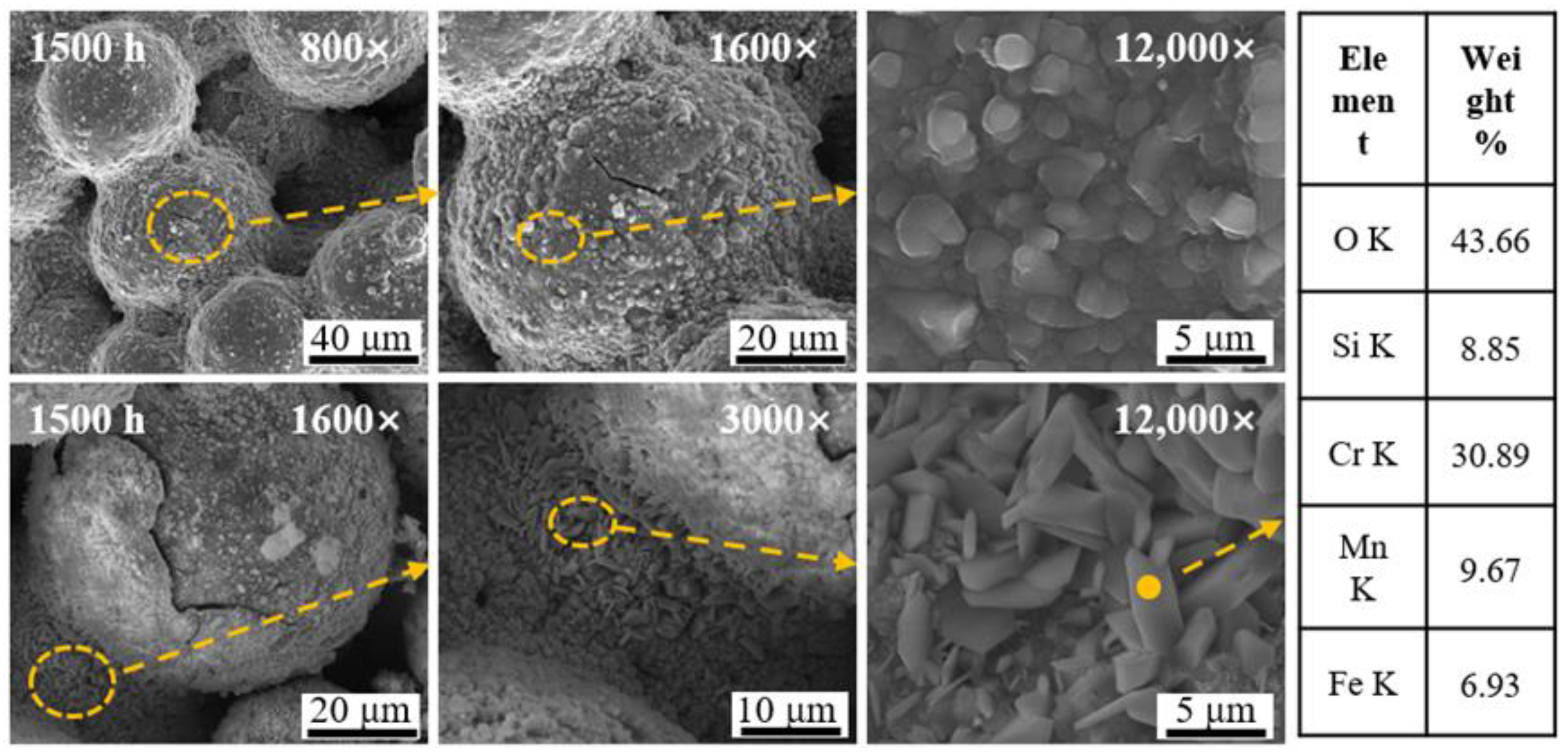
Figure 5 displays the surface morphology after oxidizing in air at 800 °C for 1500 h. The morphology indicated that the oxide scale on the substrate after oxidation in air for 1500 h had obvious cracking and peeling phenomena. The study found that the oxides formed on the stainless steel particles were granular and formed a layer of oxide scale covering the substrate. In the connecting part between the stainless steel particles, prismatic oxides appeared, mainly composed of Cr2O3.
Oxide cracking and spalling, plastic deformation of the substrate, and plastic deformation of the oxide scale can release growth and thermal stresses during the oxidation process [31,32]. In this article, it is obvious to go through the first approach. Due to the larger volume of the oxide scale generated compared to the volume of the metal consumed, the oxide scale experiences higher compressive stresses. Additionally, the vapor pressure of this type of oxide is high, making the oxide scale highly susceptible to rupture, rendering it no longer protective [33]. In addition, the coefficients of thermal expansion of different oxide layers can vary, which can cause cracking during long-term oxidation.
In this study, the first-time oxide splitting was found after 1500 h of oxidation exposure, which shows that the porous 430L substrate used in this experiment has a service life of about 1500 h in the air. If it continues to be used as an SOFC support, it will lead to breakaway oxidation of the substrate and produce a large amount of Fe-rich oxides, which will not only lead to a sharp increase in cell resistance but also accelerate cell degradation.
To analyze the structural changes in the oxide layer of the porous substrate during the oxidation process, we polished the cross-section of the sample after each oxidation cycle. Figure 6 shows the cross-sectional images taken by SEM, as well as the energy spectrum and line scans.
The SEM image shows that the oxide scale thickness increases with time. After 200 h of oxidation, the thickness of the oxide scale in the substrate was non-uniform, which may be related to the gas flow mode or the alloy’s organization. This highlights the complexity of porous alloy oxidation compared to dense alloys. The line scan in Figure 6 shows that multilayered oxide scales, including Cr2O3, FeCr2O4, MnCr2O4, and Fe-rich oxides, appear successively with increasing time. These scales are layered from the substrate side to the air side. Additionally, trace amounts of SiO2 are present in the middle of the substrate/oxide scale. During the oxidation exposure process, Fe oxides gradually increase. After a protective chromium scale is formed, the Cr element is gradually consumed. Meanwhile, Fe ions diffuse outward through the chromium scale, while O2− ions diffuse to the inside of the substrate. The oxide scale on both sides of the membrane gradually increased, causing an increase in stress between the oxide scales. Once the stress reaches a certain threshold, the oxide scale will crack and spall.
Figure 7 displays the cross-sectional morphology of the samples before and after 1500 h of oxidation. The low magnification cross-sectional SEM images (Figure 7a,b) revealed that the porosity of the specimen under dry air decreased significantly after oxidation at a constant temperature of 800 °C for 1500 h, which can greatly restrict the gas transport and may significantly increase not only the ohmic impedance of the cell but also the polarization impedance during operation.
In Figure 7c,e, it was observed that the thickness of the oxide scale varied across different regions of the substrate and there was localized cracking. The figure shows that both sides of the substrate surface were exposed to gases easily, and the oxide scale was thicker close to the planar surface side than the regions close to the central part, which is also consistent with our previous study [34]. In Figure 7d, it was more clearly observed that there was a gap layer between the substrate and the oxide scale, which may be due to the different thermal expansion coefficients of the oxide scale and the growth stress caused by the substrate/oxide scale separation [33].
Figure 7f clearly shows the presence of holes between the substrate and oxide scale, which were formed due to the generation of the outer oxide scale and elemental diffusion [35,36,37,38]. As metal oxidation is dominated by the outward diffusion of cations, a large number of cationic vacancies are formed at the substrate/oxide scale interface, and lattice relaxation in the vicinity of the vacancies leads to a change in the fractional constants, resulting in stresses. Hancock and Hurst noted that the vacancies were stress-relieved by the enhanced creep of the alloy. However, the effect of such supersaturated vacancies is not apparent because they are difficult to maintain, and they can easily accumulate at the interface between the oxide scale and the substrate, precipitating holes. The phenomenon of internal corrosion of the alloy is also visible in Figure 7f. Internal corrosion typically occurs in a water-vapor-containing atmosphere [39]. However, under sufficient oxygen content, a large number of oxygen negative ions slowly diffuse to the substrate side through the oxide scale, and with the continuation of the oxidation behavior, the substrate also suffers from varying degrees of corrosion, as well as an increase in the thickness of the outer oxide scale during the steady-state process.
Figure 7d shows that while the oxide scale was partly peeled off, there were still large areas of intact oxide scale covering the surface of the substrate. In these areas where the oxide scale was not peeled off, there were also gaps and cracks between the substrate and the oxide scale. To determine if the gaps were caused by late polishing and grinding, we carried out the observation of the cross-sectional structure and morphology by using a focused ion beam (FIB) to cut directly on the unpolished samples along the perpendicular direction of the oxide scale. Figure 8 displays the results, indicating that the gaps were not caused by polishing. Additionally, Figure 6 shows the existence of a small amount of Si and Cr-rich oxides in the gaps on the EDS surface and line scans.
Gaps may form due to stresses generated during oxide growth or differences in thermal expansion coefficients between multiple oxide layers during oxidation. This phenomenon has been reported in the literature [35,36]. Crevices hinder metal cation diffusion and slow down external oxidation. However, the inward diffusion of oxygen negative ions can cause the growth of new oxides in tiny pores or cracks of the outer oxide scale. This can eventually lead to the peeling off of the outer oxide scale, as illustrated in Figure 5.
3.5. Oxide Thickness and Substrate Life Analysis
The thickness of the oxide scale observed through SEM images is non-uniform due to the substrate’s heterogeneous organization as well as non-uniform oxidation due to elemental bias or grinding deformation during metallographic fabrication. However, the determination of the thickness of the oxide scale after oxidation by SEM is another feasible method to directly measure the cumulative oxidation [20,25].
Figure 9 shows the average thickness variation in the oxide scale over time under dry air at 800 °C. The thickness of the oxide scale increased rapidly before 50 h and then slowed down after 200, 300, and 950 h. After 1500 h of oxidation, the overall thickness was approximately 5.42 μm, with the thinnest oxide scale measuring around 3.60 μm and some thicker areas reaching 8.01 μm.
Thickness information can estimate the lifetime of the alloy and respond to the degree of oxidation. According to Huczkowski et al. [18,19], the time for the alloy to undergo breakaway oxidation increases with the thickness of the specimen. Tucker et al. proposed a threshold of 3 μm for estimating alloy lifetime based on oxide scale growth [40]. However, the porous 430L alloy used in this study did not seem to agree with the conclusions of Tucker et al. As shown in Figure 9, although the oxide scale thickness reached about 3 μm at about 300 h, no breakaway oxidation was observed in the micro-morphology (shown in Figure 3, Figure 4, Figure 5, Figure 6, Figure 7 and Figure 8), and therefore 3 μm cannot be directly used as the failure criterion for the metal-supported SOFC stainless steel substrate in the present experiment. Furthermore, we cannot rule out the feasibility of such a standard due to variations in sintering temperatures, porosities, and oxidation conditions among different alloys [41].
To ensure stable growth of the chromium scale during steady-state oxidation, the chromium flux diffusing from the substrate to the oxide scale interface must be greater than the chromium flux diffusing outward from the oxide scale. If the chromium content in the substrate falls below the critical concentration, there will be insufficient chromium supplied by the substrate, and Cr2O3 will not form a continuous and protective oxide layer. As oxygen diffuses inward, low-valent iron oxides react with Cr2O3 to form FeCr2O4 spinel. Further oxidation leads to the formation of Fe3O4 and Fe2O3 on the surface layer of the oxide scale. Huczkowski et al. showed that the critical concentration of Cr in Fe-Cr alloys was about 12 wt.% [18,19]. Although the test did not quantitatively measure the residual chromium content, it is possible to speculate on the alloy life based on the oxidized weight gain data. Koszelow et al. investigated the service life of ferrites at different temperatures. They predicted the service life of Fe27Cr in the air at 700 °C to be in the range of 5070 (±2740 h) [20,41,42]. For the porous 430L (~16 wt.% Cr) stainless steel, the weight increase ranges from 1.85 to 2.77 wt.% if all the chromium forms Cr2O3, and approximately 2.46 to 3.69 wt.% if all the chromium forms Fe/MnCr2O4 spinel. Based on the formation of Fe2O3 and a minimal amount of SiO2 at the substrate/oxide scale interface, it was determined that the weight increase threshold for the occurrence of breakaway oxidation in this study was approximately 3 wt.%.
A double logarithmic plot (Figure 9b) was created using the oxidized weight gain data, indicating a slope of 0.5 for diffusion-controlled oxidation kinetics [20,41]. The threshold line for a 3 wt.% weight gain when breakaway oxidation occurs has been labeled. From the figure, two features are apparent. Firstly, the weight gain curve under dry air conditions follows an approximately linear trend, indicating that the oxidation process was completely controlled by ion diffusion. Secondly, the time corresponding to the intersection of the curve fitting line and the 3 wt.% threshold line is also around 1500 h, which corresponds to the experimental results.
4. Conclusions
We investigated the oxidation behavior of the porous 430L substrate at 800 °C for approximately 1500 h under a dry air atmosphere. Based on the measurements of oxidation weight gain and oxide scale thickness, analysis of the oxide scale structure and microstructure, and comparison with literature studies, we reached the following conclusions:
- 1.
- The oxidation kinetics of the porous substrate under a dry air atmosphere at 800 °C exhibited two stages. The first stage was a surface reaction, which occurred relatively rapidly with a reaction rate of 2.58 × 10⁻² % h−1. The second stage conformed to Wagner’s parabolic oxidation law as a whole, with the oxidation rate decreasing markedly compared to that of the first phase (K2 = 3.66 × 10⁻³ %2 h−1) and was controlled by ion diffusion.
- 2.
- SEM and EDS analyses indicated that as the oxidation time increased, the layering of the oxide scale gradually became clear. The protective Cr2O3 scale was formed first on the outside of the substrate, followed by FeCr2O4 and MnCr2O4 spinel on the outside of the chromium scale, and Fe-rich oxides on the outermost layer of the substrate. After 1500 h of oxidation, the oxide scale exhibited localized cracking and flaking. A large area of breakaway oxidation also appeared, indicating that the porous alloy is no longer suitable as a symmetric cell support skeleton.
- 3.
- The thickness of the oxide scale gradually increased over time, but it appeared to be unevenly oxidized in different areas of the substrate. After 6, 300, 950, and 1500 h, the average thickness of the oxide scale reached 0.81, 3.35, 4.71, and 5.42 μm, respectively. Notably, no breakaway oxidation occurred even when the thickness of the oxide scale reached the threshold of 3 μm. Furthermore, the measured data showed that the porous 430L substrate can be used for about 1500 h under dry air conditions on a suggested basis of 3 wt.% weight gain, which is sufficiently long for certain mobile applications of metal-supported SOFC.
Author Contributions
K.X.: experimental investigations, writing and editing manuscript; L.Z.: conceptualization and methodology design, data analysis, writing, editing, and supervision. All authors have read and agreed to the published version of the manuscript.
Funding
The information: data, and work presented herein were supported by the Ningbo Municipal People’s Government (Grant No. 2021A-162-G, 2022Z027, and 2023Z103), and the Chinese Academy of Science.
Data Availability Statement
The data presented in this study are available in article.
Acknowledgments
The authors would like to acknowledge Zhidong Chen and Chongxi Bao from NBTM New Materials Group Co., Ltd. for the fabrication of porous substrate, and Guohua Li from the College of Chemical Engineering, Zhejiang University of Technology for partial supervision of Kai Xu and discussion of the work.
Conflicts of Interest
Author Liangzhu Zhu was employed by the company NBTM New Materials Group Co., Ltd. The remaining authors declare that the research was conducted in the absence of any commercial or financial relationships that could be construed as a potential conflict of interest.
References
- Thanedburapasup, S.; Wetchirarat, N.; Muengjai, A.; Tengprasert, W.; Wiman, P.; Thublaor, T.; Uawongsuwan, P.; Siripongsakul, T.; Chandra-Ambhorn, S. Fabrication of Mn–Co Alloys Electrodeposited on AISI 430 Ferritic Stainless Steel for SOFC Interconnect Applications. Metals 2023, 13, 612. [Google Scholar] [CrossRef]
- Singh, M.; Zappa, D.; Comini, E. Solid oxide fuel cell: Decade of progress, future perspectives and challenges. Int. J. Hydrog. Energy 2021, 46, 27643–27674. [Google Scholar] [CrossRef]
- Irshad, M.; Rafique, M.; Tabish, A.N.; Ghaffar, A.; Shakeel, A.; Siraj, K.; Ain, Q.u.; Raza, R.; Assiri, M.A.; Imran, M. Influence of Sintering Temperature on the Structural, Morphological, and Electrochemical Properties of NiO-YSZ Anode Synthesized by the Autocombustion Route. Metals 2022, 12, 219. [Google Scholar] [CrossRef]
- Tucker, M.C. Development of High Power Density Metal-Supported Solid Oxide Fuel Cells. Energy Technol. 2017, 5, 2175–2181. [Google Scholar] [CrossRef]
- Opakhai, S.; Kuterbekov, K. Metal-Supported Solid Oxide Fuel Cells: A Review of Recent Developments and Problems. Energies 2023, 16, 4700. [Google Scholar] [CrossRef]
- Golkhatmi, S.Z.; Asghar, M.I.; Lund, P.D. A review on solid oxide fuel cell durability: Latest progress, mechanisms, and study tools. Renew. Sustain. Energy Rev. 2022, 161, 112339. [Google Scholar] [CrossRef]
- Dogdibegovic, E.; Fukuyama, Y.; Tucker, M.C. Ethanol internal reforming in solid oxide fuel cells: A path toward high performance metal-supported cells for vehicular applications. J. Power Sources 2020, 449, 227598. [Google Scholar] [CrossRef]
- Dogdibegovic, E.; Wang, R.; Lau, G.Y.; Karimaghaloo, A.; Lee, M.H.; Tucker, M.C. Progress in durability of metal-supported solid oxide fuel cells with infiltrated electrodes. J. Power Sources 2019, 437, 226935. [Google Scholar] [CrossRef]
- Dogdibegovic, E.; Cheng, Y.; Shen, F.; Wang, R.; Hu, B.; Tucker, M.C. Scaleup and manufacturability of symmetric-structured metal-supported solid oxide fuel cells. J. Power Sources 2021, 489, 229439. [Google Scholar] [CrossRef]
- Dogdibegovic, E.; Wang, R.; Lau, G.Y.; Tucker, M.C. High performance metal-supported solid oxide fuel cells with infiltrated electrodes. J. Power Sources 2018, 410–411, 91–98. [Google Scholar] [CrossRef]
- Tucker, M.C.; Carreon, B.; Charyasatit, J.; Langston, K.; Taylor, C.; Manjarrez, J.; Burton, N.; LaBarbera, M.; Jacobson, C.P. R&D and Commercialization of Metal-Supported SOFC Personal Power Products at Point Source Power. In Proceedings of the 13th International Symposium on Solid Oxide Fuel Cells (SOFC-XIII), Okinawa, Japan, 6–11 October 2013; pp. 503–509. [Google Scholar]
- Zhou, Z.; Nadimpalli, V.K.; Pedersen, D.B.; Esposito, V. Degradation Mechanisms of Metal-Supported Solid Oxide Cells and Countermeasures: A Review. Materials 2021, 14, 3139. [Google Scholar] [CrossRef] [PubMed]
- Li, S.; Sang, J.; Yang, J.; Zhang, Y.; Han, B.; Liu, H.; Bao, S.; Lin, W.; Guan, W. Oxidation behaviors of the Sr2Fe1.5Mo0.5O6-δ-coated SUS430 metal interconnect in anode atmosphere for direct methanol solid oxide fuel cells. Int. J. Hydrog. Energy 2024, 56, 199–206. [Google Scholar] [CrossRef]
- Chen, P.; Yang, J.; Wang, P.; Xu, D.; Tai, Y.; Cheng, J. The suitability performance of Sr2Fe1.5Mo0.5O6-δ-coated SUS430 for SOFC interconnect application. Chem. Phys. Lett. 2022, 807, 140082. [Google Scholar] [CrossRef]
- Bongiorno, V.; Spotorno, R.; Paravidino, D.; Piccardo, P. On the High-Temperature Oxidation and Area Specific Resistance of New Commercial Ferritic Stainless Steels. Metals 2021, 11, 405. [Google Scholar] [CrossRef]
- García, I.C.; Galindo, A.N.; Bello, J.F.A.; Leal, J.M.G.; Pedemonte, J.F.B. Characterisation of High Temperature Oxidation Phenomena during AISI 430 Stainless Steel Manufacturing under a Controlled H2 Atmosphere for Bright Annealing. Metals 2021, 11, 191. [Google Scholar] [CrossRef]
- Wang, X.; Lu, Q.; Zhang, W.; Xie, Z.; Shang, C. Investigation on the Correlation between Inclusions and High Temperature Urea Corrosion Behavior in Ferritic Stainless Steel. Metals 2021, 11, 1823. [Google Scholar] [CrossRef]
- Huczkowski, P.; Christiansen, N.; Shemet, V.; Piron-Abellan, J.; Singheiser, L.; Quadakkers, W.J. Oxidation induced lifetime limits of chromia forming ferritic interconnector steels. J. Fuel Cell Sci. Technol. 2004, 1, 30–34. [Google Scholar] [CrossRef]
- Huczkowski, P.; Shemet, V.; Piron-Abellan, J.; Singheiser, L.; Quadakkers, W.J.; Christiansen, N. Oxidation limited life times of chromia forming ferritic steels. Mater. Corros. 2004, 55, 825–830. [Google Scholar] [CrossRef]
- Koszelow, D.; Makowska, M.; Marone, F.; Karczewski, J.; Jasiński, P.; Molin, S. High temperature corrosion evaluation and lifetime prediction of porous Fe22Cr stainless steel in air in temperature range 700–900 °C. Corros. Sci. 2021, 189, 109589. [Google Scholar] [CrossRef]
- Boccaccini, D.N.; Frandsen, H.L.; Sudireddy, B.R.; Blennow, P.; Persson, Å.H.; Kwok, K.; Hendriksen, P.V. Creep behaviour of porous metal supports for solid oxide fuel cells. Int. J. Hydrog. Energy 2014, 39, 21569–21580. [Google Scholar] [CrossRef]
- Mokhtari, M.; Wada, T.; Le Bourlot, C.; Duchet-Rumeau, J.; Kato, H.; Maire, E.; Mary, N. Corrosion resistance of porous ferritic stainless steel produced by liquid metal dealloying of Incoloy 800. Corros. Sci. 2020, 166, 108468. [Google Scholar] [CrossRef]
- Stefan, E.; Denonville, C.; Larring, Y.; Stange, M.; Haugsrud, R. Oxidation study of porous metal substrates for metal supported proton ceramic electrolyzer cells. Corros. Sci. 2020, 164, 108335. [Google Scholar] [CrossRef]
- Molin, S.; Kusz, B.; Gazda, M.; Jasinski, P. Evaluation of porous 430L stainless steel for SOFC operation at intermediate temperatures. J. Power Sources 2008, 181, 31–37. [Google Scholar] [CrossRef]
- Reisert, M.; Berova, V.; Aphale, A.; Singh, P.; Tucker, M.C. Oxidation of porous stainless steel supports for metal-supported solid oxide fuel cells. Int. J. Hydrog. Energy 2020, 45, 30882–30897. [Google Scholar] [CrossRef]
- Zhang, S.-L.; Li, C.-X.; Li, C.-J.; Liu, M.; Yang, G.-J. Investigation into the diffusion and oxidation behavior of the interface between a plasma-sprayed anode and a porous steel support for solid oxide fuel cells. J. Power Sources 2016, 323, 1–7. [Google Scholar] [CrossRef]
- Sarasketa-Zabala, E.; Otaegi, L.; Rodriguez-Martinez, L.M.; Alvarez, M.A.; Burgos, N.; Castro, F.; Villarreal, I. High temperature stability of porous metal substrates under highly humidified hydrogen conditions for metal supported Solid Oxide Fuel Cells. Solid State Ionics 2012, 222–223, 16–22. [Google Scholar] [CrossRef]
- Molin, S.; Dunst, K.J.; Karczewski, J.; Jasiński, P. High Temperature Corrosion Evaluation of Porous Hastelloy X Alloy in Air and Humidified Hydrogen Atmospheres. J. Electrochem. Soc. 2016, 163, C296–C302. [Google Scholar] [CrossRef]
- Karczewski, J.; Dunst, K.J.; Jasinski, P.; Molin, S. High temperature corrosion and corrosion protection of porous Ni22Cr alloys. Surf. Coat. Technol. 2015, 261, 385–390. [Google Scholar] [CrossRef]
- Molin, S.; Gazda, M.; Kusz, B.; Jasinski, P. Evaluation of 316L porous stainless steel for SOFC support. J. Eur. Ceram. Soc. 2009, 29, 757–762. [Google Scholar] [CrossRef]
- Evans, H.E. A creep analysis of the deflection test for evaluating oxide growth stresses. Mater. Sci. Eng. A Struct. Mater. Prop. Microstruct. Process. 1995, 203, 117–127. [Google Scholar] [CrossRef]
- Evans, H.E. Stress Effects in High-Temperature Oxidation of Metals. Int. Mater. Rev. 1995, 40, 1–40. [Google Scholar] [CrossRef]
- Ward, G.; Hockenhull, B.S.; Hancock, P. The Effect of Cyclic Stressing on the Oxidation of a Low-Carbon Steel. Met. Trans. 1974, 5, 1451–1455. [Google Scholar] [CrossRef]
- Fu, S.; Zhang, J.; Xu, K.; Yang, J.; Zhu, L. Fabrication, property and performance evaluation of Stainless Steel 430L as porous supports for metal supported solid oxide fuel cells. Front. Energy Res. 2023, 11, 1127900. [Google Scholar] [CrossRef]
- Brady, M.P.; Keiser, J.R.; More, K.L.; Fayek, M.; Walker, L.R.; Peascoe-Meisner, R.A.; Anovitz, L.M.; Wesolowski, D.J.; Cole, D.R. Comparison of Short-Term Oxidation Behavior of Model and Commercial Chromia-Forming Ferritic Stainless Steels in Dry and Wet Air. Oxid. Met. 2012, 78, 1–16. [Google Scholar] [CrossRef]
- Quadakkers, W.J.; Ennis, P.J.; Zurek, J.; Michalik, M. Steam oxidation of ferritic steels—Laboratory test kinetic data. Mater. High Temp. 2005, 22, 47–60. [Google Scholar] [CrossRef]
- Stringer, J. Rate-Controlling Processes in the High-Temperature Oxidation of Tantalum. J. Electrochem. Soc. 1967, 114, 428. [Google Scholar] [CrossRef]
- Tien, J.K.; Rand, W.H. The Effect of Active Element Addition on Void Formation during Oxidation. Scr. Met. 1972, 6, 55–57. [Google Scholar] [CrossRef]
- Essuman, E.; Meier, G.H.; Żurek, J.; Hänsel, M.; Quadakkers, W.J. The effect of water vapor on selective oxidation of Fe–Cr alloys. Oxid. Met. 2008, 69, 143–162. [Google Scholar] [CrossRef]
- Tucker, M.C. Progress in metal-supported solid oxide electrolysis cells: A review. Int. J. Hydrog. Energy 2020, 45, 24203–24218. [Google Scholar] [CrossRef]
- Koszelow, D.; Makowska, M.; Drewniak, A.; Cempura, G.; Jasiński, P.; Molin, S. High-temperature Corrosion of ~30 Pct Porous FeCr Stainless Steels in Air: Long-Term Evaluation Up to Breakaway. Met. Mater. Trans. A Phys. Metall. Mater. Sci. 2023, 54, 2244–2258. [Google Scholar] [CrossRef]
- Koszelow, D.; Molin, S.; Karczewski, J.; Marone, F.; Makowska, M. Morphology changes in Fe-Cr porous alloys upon high-temperature oxidation quantified by X-ray tomographic microscopy. Mater. Des. 2022, 215, 110492. [Google Scholar] [CrossRef]
Figure 1.
SEM images showing surface (a,b) and cross-sectional structure (c,d) at different magnifications.
Figure 1.
SEM images showing surface (a,b) and cross-sectional structure (c,d) at different magnifications.

Figure 2.
(a) Weight gain as a function of time, (b) square of weight gain as a function of time.

Figure 3.
XRD patterns of 430L substrate oxidized at 800 °C under dry air for different times.

Figure 4.
The surface SEM images of the porous substrate oxidized at 800 °C under dry air for different times. EDS elemental analysis corresponds to the yellow box in the SEM image.
Figure 4.
The surface SEM images of the porous substrate oxidized at 800 °C under dry air for different times. EDS elemental analysis corresponds to the yellow box in the SEM image.

Figure 5.
SEM image of the oxide cracking and flaking for 1500 h oxidation exposure under dry air. EDS elemental analysis corresponds to the position of yellow solid dot in the SEM image.
Figure 5.
SEM image of the oxide cracking and flaking for 1500 h oxidation exposure under dry air. EDS elemental analysis corresponds to the position of yellow solid dot in the SEM image.

Figure 6.
Cross-section SEM images, EDS mapping, and line scanning of the oxide scale following oxidation exposure under dry air for various durations. Note the starting position of the line scan is marked by green solid dot, and the line scan direction is not always from the steel matrix.
Figure 6.
Cross-section SEM images, EDS mapping, and line scanning of the oxide scale following oxidation exposure under dry air for various durations. Note the starting position of the line scan is marked by green solid dot, and the line scan direction is not always from the steel matrix.

Figure 7.
The cross-section SEM images of the porous substrate oxidized at 800 °C under dry air for (a) 0 h and (b–f) 1500 h under different magnifications.
Figure 7.
The cross-section SEM images of the porous substrate oxidized at 800 °C under dry air for (a) 0 h and (b–f) 1500 h under different magnifications.

Figure 8.
SEM (FIB-lamellae cut) images and EDS mapping of porous 430L alloy oxidized at 800 °C under dry air for 1500 h.
Figure 8.
SEM (FIB-lamellae cut) images and EDS mapping of porous 430L alloy oxidized at 800 °C under dry air for 1500 h.

Figure 9.
(a) The average thickness of oxide scale as a function of time, and (b) log–log plot (the dash line is the auxiliary line with a slope of 0.5).
Figure 9.
(a) The average thickness of oxide scale as a function of time, and (b) log–log plot (the dash line is the auxiliary line with a slope of 0.5).

Disclaimer/Publisher’s Note: The statements, opinions and data contained in all publications are solely those of the individual author(s) and contributor(s) and not of MDPI and/or the editor(s). MDPI and/or the editor(s) disclaim responsibility for any injury to people or property resulting from any ideas, methods, instructions or products referred to in the content. |
© 2024 by the authors. Licensee MDPI, Basel, Switzerland. This article is an open access article distributed under the terms and conditions of the Creative Commons Attribution (CC BY) license (https://creativecommons.org/licenses/by/4.0/).
Share and Cite
MDPI and ACS Style
Xu, K.; Zhu, L. Long-Term Oxidation Studies on Porous Stainless Steel 430L Substrate Relevant to Its Application in Metal-Supported SOFC. Metals 2024, 14, 475. https://doi.org/10.3390/met14040475
AMA Style
Xu K, Zhu L. Long-Term Oxidation Studies on Porous Stainless Steel 430L Substrate Relevant to Its Application in Metal-Supported SOFC. Metals. 2024; 14(4):475. https://doi.org/10.3390/met14040475
Chicago/Turabian StyleXu, Kai, and Liangzhu Zhu. 2024. "Long-Term Oxidation Studies on Porous Stainless Steel 430L Substrate Relevant to Its Application in Metal-Supported SOFC" Metals 14, no. 4: 475. https://doi.org/10.3390/met14040475
Note that from the first issue of 2016, this journal uses article numbers instead of page numbers. See further details here.