
Corrosion Behavior of 30 ppi TAD3D/5A05Al Composite in Neutral Salt Spray Corrosion

1
Key Laboratory for Ecological Metallurgy of Multimetallic Mineral, Ministry of Education, Northeastern University, Shenyang 110819, China
2
School of Metallurgy, Northeastern University, Shenyang 110819, China
3
State Power Investment Corporation Ningxia Energy and Aluminum Co., Ltd., Yinchuan 750002, China
*
Authors to whom correspondence should be addressed.
Metals 2024, 14(5), 488; https://doi.org/10.3390/met14050488
Submission received: 8 February 2024
/
Revised: 17 April 2024
/
Accepted: 19 April 2024
/
Published: 23 April 2024
(This article belongs to the Section Metal Matrix Composites)
Abstract
:This study created ceramic preforms with a 3D network structure (TAD3D) by using treated aluminum dross (TAD) and kaolin slurry, with 30 ppi polyurethane foam as a template via the sacrificial template method. TAD3D/5A05Al composites were then produced via pressureless infiltration of 5A05Al aluminum alloy into TAD3D. The corrosion behavior and resistance of TAD3D/5A05Al in salt spray were assessed via neutral salt spray corrosion (NSS), scanning electron microscopy (SEM), potentiodynamic polarization (PDP), and electrochemical impedance spectroscopy (EIS) tests. The results showed that after 24 to 360 h of NSS corrosion, the corrosion of the 5A05 matrix was primarily pitting, with pits expanding and deepening over time, and showing a tendency to interconnect. The main corrosion products were MgAl2O4, Al(OH)3, and Al2O3. As corrosion progressed, these products increased and filled cracks, pits, and grooves at the composite interface on the material’s surface. Corrosion products transferred to the grooves at the composite interface and grew on the ceramic surface. Corrosion products on the ceramic framework and the Al matrix can form a continuous passivation film covering the composite surface. PDP and EIS results indicated that the composite’s corrosion resistance decreased by 240 h but increased after that time. After 240 h, the surface passivation film can weaken corrosion effects and enhance the composite’s resistance, although it remained weaker than that of the uncorroded samples. Additionally, grooves at the composite interface deepened over time, with loosely structured corrosion products inside, potentially leading to severe localized corrosion.
1. Introduction
In three-dimensional interpenetrating phase composites (IPCs), a metal matrix and a ceramic framework intertwine, where the metal boosts strength and fracture toughness, the ceramic enhances high-temperature stability and friction performance [1]. IPC stands out for its high strength, toughness, wear resistance, and high-temperature performance, making it widely used in engineering machinery and transportation [2]. Currently, materials such as zirconia, alumina, silicon carbide, and silicon nitride are used to prepare three-dimensional porous ceramic frameworks [3]. The high cost of materials like zirconia and silicon carbide restricts IPC applications. Aluminum dross, an industrial waste generated during aluminum smelting, typically contains over 70% alumina. Researchers transformed aluminum dross, an industrial waste, into ceramics with notable properties including high modulus, strength, and low density [4]. Using TAD as the main material for TAD3D could significantly benefit waste management, utilization, and reduce IPC costs [5]. The material 5A05Al is an Al-Mg alloy with a density of 2.68 g/cm3, a melting point of approximately 607 °C, a thermal expansion coefficient of 2.32 × 10⁻⁵/°C, and a thermal conductivity of 138 W/(m·°C) which exhibits outstanding processing properties, good weldability, exceptional resistance to stress corrosion cracking, and prominent fatigue resistance [6]. These traits are ideal for creating strong, lightweight products. The preparation, microstructure, mechanical properties, and friction performance of aluminum-based IPCs have been extensively investigated in the past [7]. When used as brake disc material for high-speed heavy-duty transportation vehicles, IPC composite materials are often exposed to environments such as water mist and salt spray. However, there is limited research on the corrosion resistance of aluminum-based IPCs. Research on aluminum-based composite materials has mainly focused on ceramic particle-reinforced composites such as Al/SiCp, Al/Al2O3p, Al/graphene, Al/TiB2, etc. [8,9,10,11,12]. Studies have shown that such composite materials are prone to corrosion in marine environments. The reason for this is the susceptibility to galvanic corrosion between the particle-reinforced phase and the aluminum alloy matrix, resulting in low corrosion resistance at the interface and a relatively weak passive film formed at the interface [13,14]. These research conclusions are insufficient to predict the corrosion behavior of IPCs in marine environments because particle-reinforced aluminum-based composite materials and IPCs have completely different topological microstructures and manufacturing methods [15]. P. Bhuyan compared the corrosion resistance of interpenetrating phase composites of Al-Si alloy reinforced with SiC foam with pore sizes ranging from 10 ppi to 30 ppi. It was found that the corrosion resistance of the 20 ppi Al-Si alloy/SiC IPC was comparable to that of the unreinforced alloy. This was attributed to the optimal pore size and interconnected structure of the sample, leading to the formation of a less disruptive passive film, which significantly restricts the growth of pitting corrosion [16].
Typically, IPC preparation includes squeeze casting, pressureless infiltration, and vacuum pressure infiltration, with pressureless infiltration being simpler and more cost-effective for industrial applications [17,18,19,20]. Despite the small pore size of 30 ppi of TAD3D which presents a challenge for liquid 5A05Al infiltration under pressureless conditions, the presence of Mg in 5A05Al significantly improves its wettability with TAD3D. Additionally, the Si element enhances the flowability of the liquid metal. This synergistic effect allows the pressureless infiltration method to be successfully employed for fabricating TAD3D/5A05Al composites with a well-defined interface, leading to superior mechanical properties, wear resistance, and corrosion resistance. Notably, there is limited literature available on the fabrication process of TAD3D/5A05Al IPCs with a pore diameter of 30 ppi using the pressureless infiltration method. In this study, a 30 ppi TAD3D ceramic skeleton was prepared using aluminum dross. The TAD3D/5A05Al composite was successfully fabricated using the pressureless melt infiltration method with 5A05Al aluminum alloy. The corrosion behavior of composites in chloride environments was studied. The research not only achieved the comprehensive utilization of TAD solid waste, but also provided guidance for the long-term application of porous ceramic reinforced Al matrix composites in chloride ion environment.
2. Materials and Methods
2.1. Preparation of Composite Materials
This study used the polyurethane foam template method to manufacture TAD3D [21]. Figure 1 shows the manufacturing process of the TAD3D/5A05Al composite material. The process involved mixing treated aluminum dross (Inner Mongolia Hengsheng Environmental Protection Technology Co., Ltd., Tongliao, China) and kaolin powders (Lingshou County Huayao Mineral Products Processing Factory, Shijiazhuang, China) with Dolapix CE-64 (dispersant) (Zschimmer-Schwarz (China) Ltd., Foshan, China), Polyvinyl alcohol (PVA) (binder) (Changchun Chemical (Jiangsu) Co., Ltd., Changshu, China), and carboxymethyl cellulose (CMC) (thickener) (Shanghai Shenguang Edible Chemicals Co., Ltd., Shanghai, China) in ratios of 80, 17, 2, 0.5, and 0.5 wt.%, respectively. The compositions of TAD and kaolin are shown in Table 1. This mixture was then added to distilled water and milled with ZrO2 balls in a nylon jar for 12 h to create a 70% solid slurry and adjusted to pH 9.1–9.8 with ammonia water. A polyurethane sponge template (Changzhou Mukun Sponge Technology Co., Ltd., Changzhou, China) was dipped into the slurry, the excess was removed via double-roll extrusion (Yiwu Juandu Crafts Factory, Jinhua, China), and air-dried to reveal a coated sponge. This sponge was microwaved (Xuzhou Zhongneng Drying Equipment Co., Ltd., Xuzhou, China) for 15 to 20 min, then sintered in a furnace (KSL1700X, Hefei Kejing Material Technology Co., Ltd., Hefei, China) at 5 °C/min to 1350 °C for 3 h, producing TAD3D.
The TAD3D/5A05Al composite material was prepared using the pressureless casting method [22]. The 5A05Al alloy’s chemical composition (Guangxi Nannan Aluminum Processing Co., Ltd., Guangxi, China) is shown in Table 2. The 5A05Al aluminum alloy block was placed in a corundum crucible (Yixing Woniu Ceramic Technology Co., Ltd., Wuxi, China), and the crucible along with the TAD3D block was positioned in a crucible resistance furnace (SG-2, Henan Eng Furnace Machinery Equipment Co., Ltd., Zhengzhou, China), with the temperature raised to 950 °C. The residue from the surface of the 5A05 Al in the crucible was removed, and the aluminum melt was stirred uniformly. The TAD3D was placed into the aluminum melt, the crucible was tightly pressed with refractory materials, and maintained at 950 °C for 30 min, allowing the 5A05Al solution to fully infiltrate the TAD3D. After cooling, the TAD3D/5A05Al composite was formed. TAD3D/5A05Al specimens with dimensions of 10 × 10 × 6 mm3 were cut using a metallographic cutting machine (Laizhou Weiyi Machinery Manufacturing Co., Ltd., Yantai, China). The next stage was to select a 10 × 10 mm2 surface of the sample, sand it with a series of silicon carbide papers, then polish it with 1.5 μm diamond paste to achieve a mirror-finished surface. Then, clean it with distilled water, degrease it with acetone, and dry it.
2.2. Neutral Salt Spray Corrosion
The NSS was conducted using an automated neutral salt spray chamber (ZK-60K, Dongguan Zhenke Testing Equipment Co., Ltd., Dongguan, China). According to ASTM B117 standard [23], the corrosive solution consisted of 5 wt.% NaCl with a pH range of 6.5 to 7.2 in a neutral solution. Experimental durations were set at 24, 72, 144, 240, and 360 h, with a test temperature of (35 ± 1) °C. After reaching the designated time, the samples were removed from the salt spray chamber and dried in a convection drying oven (STIK Instrument Equipment (Shanghai) Co., Ltd., Shanghai, China) for at least 2 h, then sealed for storage.
2.3. Surface Analysis
The polished TAD3D/5A05Al samples were etched with Keller’s solution (HCl:HF:HNO3:H2O = 3:2:5:190). The samples were immersed in Keller’s reagent for 10–20 s, then rinsed with warm water, wiped with alcohol, and dried with a cold air blower. The optical microscope studies were conducted with an inverted metallurgical microscope (BMM-2308DV, Shanghai BATO Instruments Co., Ltd., Shanghai, China).
In order to observe the surface corrosion morphology of the samples, the samples were first rinsed under flowing water using a soft brush to remove loosely attached or large-volume corrosion products. Subsequently, the samples were immersed in a 70 vol.% HNO3 solution for 2 min to remove corrosion products and then washed with plenty of distilled water. The corrosion microstructures on the sample surface were observed using a scanning electron microscope equipped with an energy-dispersive X-ray spectrometer (EDS) (HITACHI S4800, Tokyo, Japan), and the composition of the corrosion products was analyzed.
2.4. Electrochemical Measurement
The electrochemical properties of TAD3D/5A05Al samples corroded under NSS for various durations were investigated using an electrochemical workstation (CHI 790E, Shanghai Chenhua Instrument Co., Ltd., Shanghai, China). Electrochemical testing comprised PDP and EIS, conducted using a three-electrode system. A standard calomel electrode (saturated potassium chloride solution) served as the reference electrode, with a platinum foil employed as the auxiliary electrode [19]. The TAD3D/5A05Al was connected to copper wire, sealed with cold mounting resin, and used as the working electrode. The area of the test sample exposed to the electrolyte was 1 cm2. At room temperature, the sample was immersed in a 3.5% NaCl solution for 30 min. After stabilizing the open-circuit potential (OCP), PDP and EIS were measured. A scan rate of 0.25 mV/s was used for the cathodic-to-anodic scan, covering the range of OCP ± 600 mV for PDP measurements. During EIS measurements, a frequency range of 10−2 to 106 Hz was employed, with a sinusoidal perturbation signal of 10 mV added. The data were fitted using ZView software (Ver. 2.70, Scribner, LLC, Southern Pines, NC, USA) after the tests.
3. Results and Discussion
3.1. Microstructure of TAD3D/5A05Al
Figure 2 illustrates the raw materials, TAD3D, and sample photographs for the fabrication of TAD3D/5A05Al composite materials. Figure 2a displays the SEM image of processed aluminum dross, revealing its spherical shape. The sintered TAD3D framework, shown in Figure 2b, transformed into ceramic through body sintering, appearing white with a shrinkage rate of approximately 19%. The compressive strength of the framework was about 2~5 MPa, and the porosity was around 30 ppi. Figure 2c shows a photograph of the cut TAD3D/5A05Al sample, displaying a defect-free appearance. The black striped pattern on the surface represents the TAD3D framework, with approximately 23–26 pores formed per square centimeter. The pore diameter ranged from 1.7 to 2.0 mm and was filled with the 5A05Al alloy exhibiting a silver-white metallic luster. The wetting property between the TAD3D framework and 5A05Al alloy was excellent, resulting in a dense interface between TAD3D and 5A05Al.
Figure 3 shows the microstructure of the uncorroded TAD3D/5A05Al composite. Figure 3a shows that the pores of the ceramic phase were completely filled with 5A05 aluminum alloy. TAD3D was manufactured using the polyurethane foam template method, and it contained triangular voids left by the combustion of the polyurethane foam. In this study, the pressureless melt infiltration method was employed to completely fill the triangular voids of TAD3D with the solution of 5A05Al, achieving a dense IPC structure between 5A05Al alloy and TAD3D. This structure is also referred to as a co-continuous structure, wherein the 5A05 aluminum alloy not only fills the macroscopic large pores with a diameter of 1.7 to 2.0 mm but also completely fills the small voids in TAD3D. The 5A05 aluminum alloy formed a fully interconnected three-dimensional network structure in the composite material, compensating for the hollow defects in the TAD3D framework pillars and significantly enhancing the mechanical and corrosion resistance properties of TAD3D/5A05Al [24]. Figure 3b shows the microstructure of 5A05Al, which revealed that there were a large number of second-phase particles distributed in 5A05Al. Figure 3(c-1,c-2) shows the microstructure of the interface between TAD3D and 5A05Al. It can be seen that the interface between 5A05Al and TAD3D was clear, with a tight bond.
Figure 3(d-1,e-1) show the micromorphology of the second-phase particles in the 5A05 matrix. Figure 3(d-2–d-4,e-2–e-4) show the results of the EDS point scan. Figure 3(d-4,e-3,e-4) show the composition of α-Al phase. In Al-Mg alloys, the α-Al matrix is mainly solid-soluted with Mg and generally does not contain other solutes (Mn, Fe, Cr, or Si) [25]. It can be seen that the α-Al phase was Al-Mg7.4. The results of Figure 3(d-2,e-2) show that the blocky and dendritic precipitates on the aluminum matrix may be (FeMn)Al6, with a grain size of over 10 to 13 μm. The results of Figure 3(d-3) show that the precipitates with a grain size of about 2 μm and darker color in the aluminum matrix may be Mg2Al3 [26,27,28].
Figure 4 shows the SEM and EDS surface scanning images of the composite material. A clear deep crack can be seen between 5A05Al and TAD3D, which is the interface of the composite material. The bonding between 5A05Al and TAD3D is a physical bonding, which can be observed more clearly at the interface after etching with Keller’s reagent. EDS showed that 5A05Al alloy was mainly composed of Al, Mn, Mg, Si, and Fe elements, which was consistent with its alloy composition. A Si–Mg enrichment band can be observed on the right side of the element distribution map, which may be the precipitated phase Mg2Si, which was not observed in Figure 3 [29]. Al, O, Si, and Mg elements were enriched in TAD3D, because TAD3D was prepared from Al2O3, MgAl2O4, and MgO in TAD and Al2O3, SiO2 in kaolin. For the same reason, there was almost no Fe and Mn element in TAD3D. It is worth noting that the silicon element in TAD3D decreased significantly near the interface. It can be seen from Figure 4a that the ceramic surface near the interface was dense, while TAD3D had more pores away from the interface. The silicon element in TAD3D was mainly distributed in the porous area. The dense ceramic layer at the interface may be due to the fact that during the composite process, the aluminum melt reacted with SiO2 in TAD3D to reduce SiO2 near the interface to the Si, and the Si diffused into the aluminum melt [30]. It may also be caused by the unevenness of the ceramic itself.
3.2. Microstructure of 5A05Al Matrix in TAD3D/5A05Al after Removal of NSS Corrosion Products
Figure 5 illustrates the microstructure of 5A05Al after the removal of corrosion products. Figure 5(a-1–a-3) show the microstructure after 24 h of NSS corrosion, with few micron-sized pits observed on the surface of the 5A05Al alloy. Figure 5(b-1–b-3) reveal the microstructure after 72 h of NSS corrosion. Compared with the 24 h samples, deep pits with several microns in diameter can be observed. The corrosion behavior was mainly mild pitting. This phenomenon was likely caused by galvanic corrosion in the β-phase Mg2Al3. The potential difference between phases plays a significant role, with a larger difference increasing the likelihood of corrosion. In the 5A05 aluminum alloy, the potential of α-Al was around −800 mV, while the β-phase Mg2Al3 was around −900 mV. This made the β-phase more negatively charged and therefore more susceptible to anodic dissolution. Microstructures in Figure 5(c-1–c-3) reveal the surface of 5A05Al after 144 h of NSS corrosion. Larger pitting pits with diameters of 10 to 20 μm were observed on the sample surface. This proved that extending the NSS time further promoted the occurrence and development of pitting. The depth of pitting corrosion increased, leading to exfoliation corrosion and a decrease in the corrosion resistance of the material. Microstructures in Figure 5(d-1–d-3) depict the surface of 5A05Al after 240 h of NSS corrosion. Compared to the 144 h mark, the areas of pitting corrosion continued to increase and take on an elliptical shape. This indicated the presence of localized corrosion features with corrosion areas predominantly appearing as punctate or cellular. Notably, the edges of the pitting corrosion pits on the surface of 5A05Al were covered by a small amount of aluminum oxide. It is worth mentioning that some metastable pitting pores continued to grow, leading to diameters exceeding 20 μm in certain cases. Figure 5(e-1–e-3) show the microstructure after 360 h of NSS corrosion. Compared with the previous corrosion characteristics, it can be seen that the corrosion was further intensified, the pitting pits on the surface were enlarged, and there was a tendency to connect with each other.
3.3. Microstructure of the Interface in TAD3D/5A05Al with NSS Corrosion Products
Figure 6 shows the SEM images of the corrosion products at the interface of TAD3D and 5A05Al after NSS corrosion for 24, 72, 144, 240, and 360 h, respectively. Figure 6(a-1–a-3) show that after 24 h of NSS corrosion, the interface was intact. Pores can be seen on the TAD3D, which were defects left by incomplete densification of TAD sintering. No obvious pitting was observed on the 5A05Al side. Figure 6(b-1–b-3) show that after 72 h of NSS corrosion, a small amount of spot-like agglomerated corrosion products were generated on the 5A05Al side. The pores on the TAD3D were reduced and filled with corrosion products. Figure 6(c-1–c-3) show that after 144 h of NSS corrosion, cluster-like corrosion products with a diameter of about 200 μm appeared on the 5A05Al side. The TAD3D, especially the composite interface, was covered by corrosion products. Figure 6(d-1–d-3) show that after 240 h of NSS corrosion, there were still large spherical protruding corrosion products on the 5A05 substrate, and severe pitting may have occurred below them. There was no obvious interface in the composite material. Figure 6(e-1–e-3) show that after 360 h of NSS corrosion, there were deep grooves at the interface between 5A05 and TAD3D, which were filled with corrosion products, but still contained deep holes and grooves with loose structures. These types of defect are very dangerous because local corrosion can reach deep into the composite and destroy the material.
To further investigate the composition of the corrosion products at the interface of the TAD3D/5A05 composite material after 72 h of NSS, the interface was magnified. Figure 7 shows the EDS point scanning image of the corrosion products at the interface. As can be seen in Figure 7a, the ceramic skeleton at the interface groove was covered with a large amount of lamellar structure material. These substances may be formed by the deposition of substances that were dissolved after the 5A05 matrix was corroded and transferred with the corrosive liquid during the corrosion process. According to the point scanning results of Figure 7(b-1–b-3), the main components of the corrosion products were O, Al, and Mg. Therefore, the corrosion products may be composed of MgAl2O4, Al(OH)3, and Al2O3. Based on Figure 6 and Figure 7, it can be seen that the TAD3D skeleton easily adsorbed and grew corrosion products, so that the composite interface was filled with corrosion products. The corrosion products generated by the 5A05 matrix were combined with the corrosion products on the TAD3D to form a continuous passivation layer, which had some corrosion protection effect.
3.4. Microstructure of the Interface in TAD3D/5A05Al after Removal of NSS Corrosion Products
To better understand the microstructure of the 5A05Al/TAD3D interface after NSS, SEM and EDS analysis were performed after removing the corrosion products. Figure 8 shows the SEM images of the composite interface after removing the corrosion products from the 24 and 360 h samples, as well as the EDS analysis images. Figure 8(a-1–a-3) show the morphology of the composite interface after removing the corrosion products from the 24 h sample. It can be seen that although there were more pores on the TAD3D, the TAD3D and 5A05 matrix were relatively tight. As can be seen from the element distribution map in Figure 8(a-4), although the corrosion products were removed, there were still Na and Cl enrichment points. Figure 8(b-1–b-3) show the morphology of the composite interface after removing the corrosion products from the 360 h sample. Compared with 24 h, it can be clearly seen that a large gap formed between the TAD3D and the 5A05 matrix. This gap may have been caused by local corrosion at the interface of the two phases during the corrosion process. It can be seen that the gap was deep and the internal structure was loose. As can be seen from the element distribution map in Figure 8(b-4), some NaCl remained in the groove, indicating that the loose structure in the groove made it easy for Cl– to penetrate into the groove and remain there for a long time, leading to serious corrosion. Overall, combined with the analysis of Figure 6 and Figure 7, it can be seen that although the corrosion products filled the grooves of the composite interface, the TAD3D and 5A05Al jointly produced continuous corrosion products. However, the interface of the composite material was still the weak link of corrosion.
3.5. PDP of TAD3D/5A05Al with NSS Corrosion Products
To investigate the corrosion resistance of samples after different NSS times, PDP tests were conducted on specimens with corrosion products. Figure 9 presents the PDP polarization curves of TAD3D/5A05Al with corrosion products after different NSS durations. The polarization curve trends of TAD3D/5A05Al were similar at different NSS times. Table 3 provides the Ecorr and Icorr values of TAD3D/5A05Al at various NSS corrosion times. It is evident from the table that, during the NSS corrosion period from 0 to 144 h, the Ecorr value decreased. After 144 h of NSS corrosion, Ecorr decreased to a minimum of −0.932 V, indicating the breakdown of the passive film and a reduction in corrosion resistance. As NSS corrosion progressed from 240 to 360 h, the Ecorr value increased, reaching −0.712 V after 360 h of NSS corrosion, slightly lower than the Ecorr value of the uncorroded sample (−0.710 V). This suggested that, after 240 h of NSS corrosion, a significant amount of corrosion products formed on the surface of the composite material, protecting it and leading to an increase in corrosion voltage, a decrease in corrosion rate, and enhanced corrosion resistance. By 360 h of NSS corrosion, a complete corrosion product film formed on the surface, continuing to elevate the corrosion voltage, exerting inhibitory effects on corrosion, further reducing the corrosion rate, and enhancing corrosion resistance.
The variation in Icorr from Table 3 also revealed a similar trend. From 0 to 144 h of NSS corrosion, Icorr values increased, reaching a maximum of 0.682 µA·cm−2 after 144 h of NSS corrosion. This indicated that the passive film was disrupted, leading to the maximum corrosion current and an increase in corrosion rate, resulting in the lowest corrosion resistance. As NSS corrosion progressed from 240 to 360 h, Icorr values decreased. After 360 h of NSS corrosion, Icorr decreased to 0.139 µA·cm−2, lower than the Icorr value of the uncorroded sample (0.396 µA·cm−2). This suggested that, after 240 h of NSS corrosion, a substantial amount of corrosion products formed on the surface of the composite material, providing protective effects, reducing the corrosion current, decreasing the corrosion rate, and enhancing corrosion resistance. By 360 h of NSS corrosion, a complete corrosion product film formed on the surface, further reducing the corrosion current, inhibiting corrosion, decreasing the corrosion rate, and improving corrosion resistance.
3.6. EIS of TAD3D/5A05Al with NSS Corrosion Products
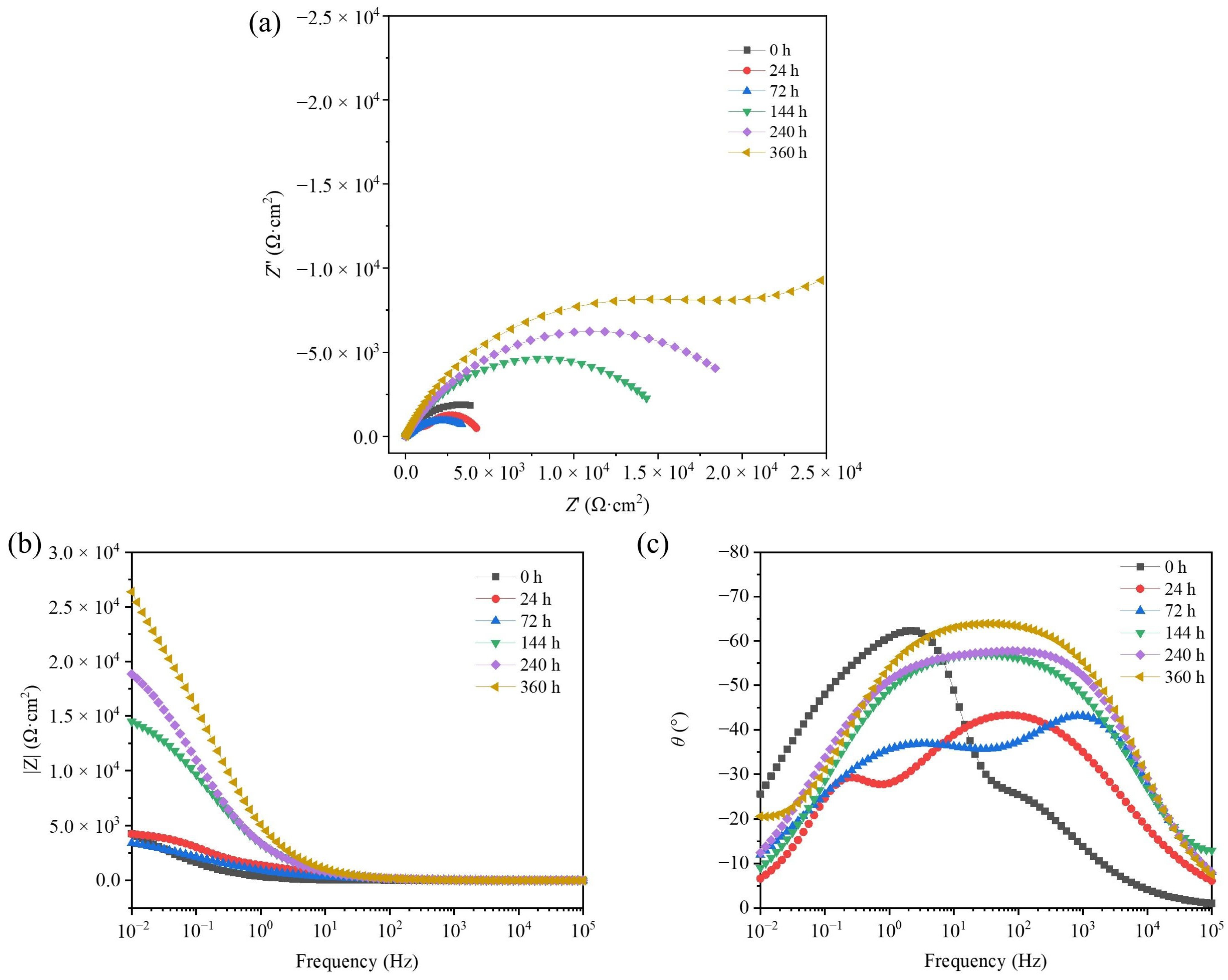
Figure 10 depicts the EIS of TAD3D/5A05Al with corrosion products. The Nyquist plot comprises capacitive arcs (Figure 10a). The high-frequency capacitive arc corresponds to the corrosion products on the surface of TAD3D/5A05Al, representing the resistance of the corrosion products and the surface passive film. The radius of the high-frequency capacitive arc was directly proportional to corrosion resistance. The low-frequency capacitive arc corresponds to electrochemical corrosion reactions on the electrode surface. With the increase in NSS time, the capacitance resistance arc in the high-frequency region initially decreased and then increased, indicating the slow formation of corrosion products on the surface of TAD3D/5A05Al. From Figure 10b, it can be observed that |Z| showed a trend of first decreasing and then increasing with the increase in NSS time, and the peaks of the high-frequency and mid-frequency θ shifted towards the low-frequency direction. From Figure 10c, it can be observed that in the Bode plot, the separation degree of the two-phase angle peaks at 24 h was slight. This was because the pit corrosion extended laterally and longitudinally, and when the pitting had just developed into intergranular corrosion of precipitated phases and α-Al, the intergranular corrosion was not yet apparent. However, after NSS 72 h, the radius of the capacitive arc in the low-frequency region in the Nyquist plot was smaller compared to NSS 24 h, indicating a decrease in corrosion resistance. In the Bode plot, it can be seen that compared to the two-phase angles at 24 h, the separation degree of the two-phase angles at 72 h was more pronounced. This was because when corrosion reached the interface of TAD3D/5A05Al, there were tiny cracks caused by thermal expansion at the TAD3D and 5A05Al interface. Underneath the cracks, a new interface was formed, leading to the appearance of a low-frequency phase angle peak. As the NSS corrosion time increased, the corrosion severity between grains and interfaces intensified, and the gap at the interface between TAD3D and 5A05Al widened, resulting in a clear separation of the two-phase angle peaks. After NSS 144 h, the radius of the capacitive arc in the Nyquist plot decreased compared to NSS 72 h, while the phase angle in the low-frequency region began to increase, and the impedance modulus increased, indicating the initiation of corrosion product formation. Following NSS 240 h, the capacitive arc radius increased, and the impedance modulus at low frequency significantly rose. The peak values of the phase angle in the low-, medium-, and high-frequency regions all increased, suggesting an increase in corrosion products and an enhancement in material corrosion resistance. After NSS 360 h, the capacitive arc radius significantly increased compared to NSS 240 h, and the impedance modulus at low frequency markedly rose. The low-frequency phase angle region became wider, and the peak values of the phase angle were close to those at NSS 240 h. According to the morphology of the corrosion products, the corrosion product layer at this stage was most dense, resulting in an improved corrosion resistance.
4. Conclusions
- A TAD3D skeleton with a compressive strength of about 2~5 MPa and pores of about 30 ppi was obtained via the sacrificial template method with TAD and kaolin as raw materials. After pressureless infiltration, TAD3D can be well bonded with the 5A05Al interface to form TAD3D/5A05 composites.
- After 24 to 360 h NSS corrosion, the corrosion of the 5A05 matrix was mainly pitting corrosion. The pits expanded and deepened with the increase in corrosion time, and there was a trend of mutual connection.
- The main corrosion products were MgAl2O4, Al(OH)3, and Al2O3. With the increase in corrosion time, the corrosion products increased and filled the cracks, pitting pits, and grooves of the composite material surface. During the corrosion process, the corrosion products transferred to the grooves of the composite interface and grew on the ceramic surface. The corrosion products on the ceramic skeleton formed a continuous passivation film with the corrosion products generated on the Al matrix, covering the surface of the composite material. However, the passivation film did not stop the corrosion from continuing. The grooves of the composite interface gradually deepened with the increase in corrosion time, and the corrosion products in the grooves were loose, which may have led to serious local corrosion.
- PDP and EIS analyses showed that for TAD3D/5A05, Ecorr initially decreased then increased and Icorr first rose and then fell. The high-frequency impedance arc radius and the impedance value both decreased before increasing, while the low-frequency phase angle grew, indicating an initial drop then a rise in corrosion resistance. With the progress of corrosion, the corrosion products on the surface of the composite material continued to increase. After 240 h, there were enough corrosion products to form a continuous passivation film. The passivation film can weaken the corrosion effect and increase the corrosion resistance of the composite material, but its corrosion resistance was still weaker than that of the uncorroded sample.
Therefore, the long-term corrosion resistance of TAD3D/5A05 in chloride environments is poor and it is advisable to consider other protective measures for this composite material.
Author Contributions
Conceptualization, G.F., L.J., H.Y. and Z.L.; writing original draft preparation, Z.L., H.Y. and Y.C.; writing—review and editing, Z.L., H.Y., Y.C., G.F. and L.J.; supervision, G.F. and L.J. project administration, Z.L., G.F. and L.J.; funding acquisition, G.F. All authors have read and agreed to the published version of the manuscript.
Funding
This research was funded by the National Natural Science Foundation of China (U20A20239).
Data Availability Statement
The original contributions presented in the study are included in the article, further inquiries can be directed to the corresponding author/s.
Conflicts of Interest
Author Hongliang Yang was employed by the company State Power Investment Corporation Ningxia Energy and Aluminum Co., Ltd. The remaining authors declare that the research was conducted in the absence of any commercial or financial relationships that could be construed as a potential conflict of interest.
References
- Kota, N.; Charan, M.S.; Laha, T.; Roy, S. Review on development of metal/ceramic interpenetrating phase composites and critical analysis of their properties. Ceram. Int. 2022, 48, 1451–1483. [Google Scholar] [CrossRef]
- Jiang, L.; Jiang, Y.-L.; Yu, L.; Yang, H.-L.; Li, Z.-S.; Ding, Y.-D.; Fu, G.-F. Fabrication, microstructure, friction and wear properties of SiC3D/Al brake disc-graphite/SiC pad tribo-couple for high-speed train. Trans. Nonferrous Met. Soc. China 2019, 29, 1889–1902. [Google Scholar] [CrossRef]
- Wang, D.; Zheng, Z.; Lv, J.; Xu, G.; Zhou, S.; Tang, W.; Wu, Y. Enhanced thermal conductive 3D-SiC/Al-Si-Mg interpenetrating composites fabricated by pressureless infiltration. Ceram. Int. 2017, 43, 1755–1761. [Google Scholar] [CrossRef]
- Bandil, K.; Vashisth, H.; Kumar, S.; Verma, L.; Jamwal, A.; Kumar, D.; Singh, N.; Sadasivuni, K.K.; Gupta, P. Microstructural, mechanical and corrosion behaviour of Al–Si alloy reinforced with SiC metal matrix composite. J. Compos. Mater. 2019, 53, 4215–4223. [Google Scholar] [CrossRef]
- Yu, L.; Liu, Y.; Cao, X.; Yan, Y.; Zhang, C.; Jiang, Y. Research of Microstructure, Phase, and Mechanical Properties of Aluminum-Dross-Based Porous Ceramics. J. Renew. Mater. 2023, 11, 3057–3072. [Google Scholar] [CrossRef]
- Li, J.; Li, W.; Zhao, C.; Xing, Y.; Lang, F.; Hou, X. Experimental Investigation of Crack Propagation and Strain Fields Evolution around a Crack Tip in 5A05 Aluminum Alloy. Metals 2018, 8, 685. [Google Scholar] [CrossRef]
- Yu, L.; Hao, S.; Nong, X.; Cao, X.; Zhang, C.; Liu, Y.; Yan, Y.; Jiang, Y. Comparative Study on the Corrosion Resistance of 6061Al and SiC3D/6061Al Composite in a Chloride Environment. Materials 2021, 14, 7730. [Google Scholar] [CrossRef] [PubMed]
- Lattanzi, L.; Etienne, A.; Li, Z.; Chandrashekar, G.T.; Gonapati, S.R.; Awe, S.A.; Jarfors, A.E.W. The effect of Ni and Zr additions on hardness, elastic modulus and wear performance of Al-SiCp composite. Tribol. Int. 2022, 169, 107478. [Google Scholar] [CrossRef]
- Wang, Y.; Normand, B.; Mary, N.; Yu, M.; Liao, H. Effects of ceramic particle size on microstructure and the corrosion behavior of cold sprayed SiCp/Al 5056 composite coatings. Surf. Coat. Technol. 2017, 315, 314–325. [Google Scholar] [CrossRef]
- Lee, T.; Chae, H.; Shin, S.; Cho, S.; Lee, S.-K.; Lee, S.Y.; An, K.; Ryu, H.J. Overcoming brittleness of high volume fraction Al/SiCp composites by controlling interface characteristics. Mater. Des. 2022, 222, 111038. [Google Scholar] [CrossRef]
- Ramadan, S.; Taha, M.A.; El-Meligy, W.M.; Saudi, H.A.; Zawrah, M.F. Influence of Graphene Content on Sinterability and Physico-Mechanical Characteristics of Al/Graphene Composites Prepared via Powder Metallurgy. Biointerface Res. Appl. Chem. 2022, 13, 192. [Google Scholar] [CrossRef]
- Ayodele, O.O.; Babalola, B.J.; Olubambi, P.A. Characterization, nanomechanical, and wear attributes of sintered Al–TiB2 composites. J. Mater. Res. Technol. 2023, 24, 4153–4167. [Google Scholar] [CrossRef]
- Ji, Y.-Y.; Xu, Y.-Z.; Zhang, B.-B.; Behnamian, Y.; Xia, D.-H.; Hu, W.-B. Review of micro-scale and atomic-scale corrosion mechanisms of second phases in aluminum alloys. Trans. Nonferrous Met. Soc. China 2021, 31, 3205–3227. [Google Scholar] [CrossRef]
- Senthilkumar, J.; Balasubramanian, M.; Balasubramanian, V. Studies on effect of powder metallurgy on the corrosion behaviour of Al-Al2O3p composites. Adv. Mater. Process. Technol. 2023, 9, 859–874. [Google Scholar] [CrossRef]
- Jiang, Y.; Xu, P.; Zhang, C.; Jin, F.; Li, Y.; Cao, X.; Yu, L. Simulation and Experimental of Infiltration and Solidification Process for Al(2)O(3(3D))/5083Al Interpenetrating Phase Composite for High Speed Train Prepared by Low-Pressure Infiltration. Materials 2023, 16, 6634. [Google Scholar] [CrossRef]
- Bhuyan, P.; Kota, N.; Bairagi, D.; Sahasrabudhe, S.; Roy, S.; Mandal, S. Unveiling the corrosion perspective of Al-Si alloy/SiC foam interpenetrating phase composite. Mater. Today Commun. 2023, 35, 105495. [Google Scholar] [CrossRef]
- Wang, D.; Zheng, Z.; Lv, J.; Xu, G.; Zhou, S.; Tang, W.; Wu, Y. Multimodal particle distribution in 3D-SiC/Al-Si-Mg interpenetrating composite fabricated by pressureless infiltration. Ceram. Int. 2018, 44, 19851–19858. [Google Scholar] [CrossRef]
- Vijayan, K.; Ramalingam, S.; Raeez Akthar Sadik, M.; Prasanth, A.S.; Nampoothiri, J.; Pablo Escobedo-Diaz, J.; Shankar, K. Fabrication of Co-Continuous ceramic composite (C4) through gas pressure infiltration technique. Mater. Today Proc. 2021, 46, 1013–1016. [Google Scholar] [CrossRef]
- Asar, A.; Zaki, W. A comprehensive review of the mechanisms and structure of interpenetrating phase composites with emphasis on metal-metal and polymer-metal variants. Compos. Part B Eng. 2024, 275, 111314. [Google Scholar] [CrossRef]
- Roy, S.; Albrecht, P.; Weidenmann, K.A. Influence of Ceramic Freeze-Casting Temperature on the Anisotropic Thermal Expansion Behavior of Corresponding Interpenetrating Metal/Ceramic Composites. J. Mater. Eng. Perform. 2023, 32, 8795–8806. [Google Scholar] [CrossRef]
- Sousa, E.; Silveira, C.B.; Fey, T.; Greil, P.; Hotza, D.; de Oliveira, A.P.N. LZSA glass ceramic foams prepared by replication process. Adv. Appl. Ceram. 2013, 104, 22–29. [Google Scholar] [CrossRef]
- Liu, J.; Binner, J.; Higginson, R. Dry sliding wear behaviour of co-continuous ceramic foam/aluminium alloy interpenetrating composites produced by pressureless infiltration. Wear 2012, 276–277, 94–104. [Google Scholar] [CrossRef]
- ASTM B117-19; Standard Practice for Operating Salt Spray (Fog) Apparatus. ASTM International: West Conshohocken, PA, USA, 2019.
- Li, X.; Xia, W.; Yan, H.; Chen, J.; Li, X. Improving strength and corrosion resistance of high Mg alloyed Al–Mg–Mn alloys through Ce addition. Corros. Eng. Sci. Technol. 2020, 55, 381–391. [Google Scholar] [CrossRef]
- Goswami, R.; Spanos, G.; Pao, P.S.; Holtz, R.L. Microstructural Evolution and Stress Corrosion Cracking Behavior of Al-5083. Metall. Mater. Trans. A 2011, 42, 348–355. [Google Scholar] [CrossRef]
- Engler, O.; Kuhnke, K.; Krupp, H.J.; Hentschel, T. Characterization of Intergranular Corrosion in AA 5xxx Al-Mg Alloys. Pract. Metallogr. 2020, 57, 545–568. [Google Scholar] [CrossRef]
- Grasserbauer, J.; Weißensteiner, I.; Falkinger, G.; Kremmer, T.M.; Uggowitzer, P.J.; Pogatscher, S. Influence of Fe and Mn on the Microstructure Formation in 5xxx Alloys—Part I: Evolution of Primary and Secondary Phases. Materials 2021, 14, 3204. [Google Scholar] [CrossRef]
- Kamunur, K.; Bekmurat, N.K.; Milikhat, B.; Abdulkarimova, R.G. Microstructure and thermal properties of an Al–Mg alloy solidified at high temperature in the argon atmosphere. Combust. Plasma Chem. 2019, 19, 17–23. [Google Scholar] [CrossRef]
- Seth, P.P.; Parkash, O.; Kumar, D. Structure and mechanical behavior of in situ developed Mg(2)Si phase in magnesium and aluminum alloys—A review. RSC Adv 2020, 10, 37327–37345. [Google Scholar] [CrossRef]
- Islam, M.M.; Sawahata, J.; Akimoto, K.; Sakurai, T. Formation of silicon layer through aluminothermic reduction of quartz substrates. Front. Mater. 2022, 9, 977869. [Google Scholar] [CrossRef]
Figure 1.
Manufacturing process of the TAD3D/5A05Al composite material.
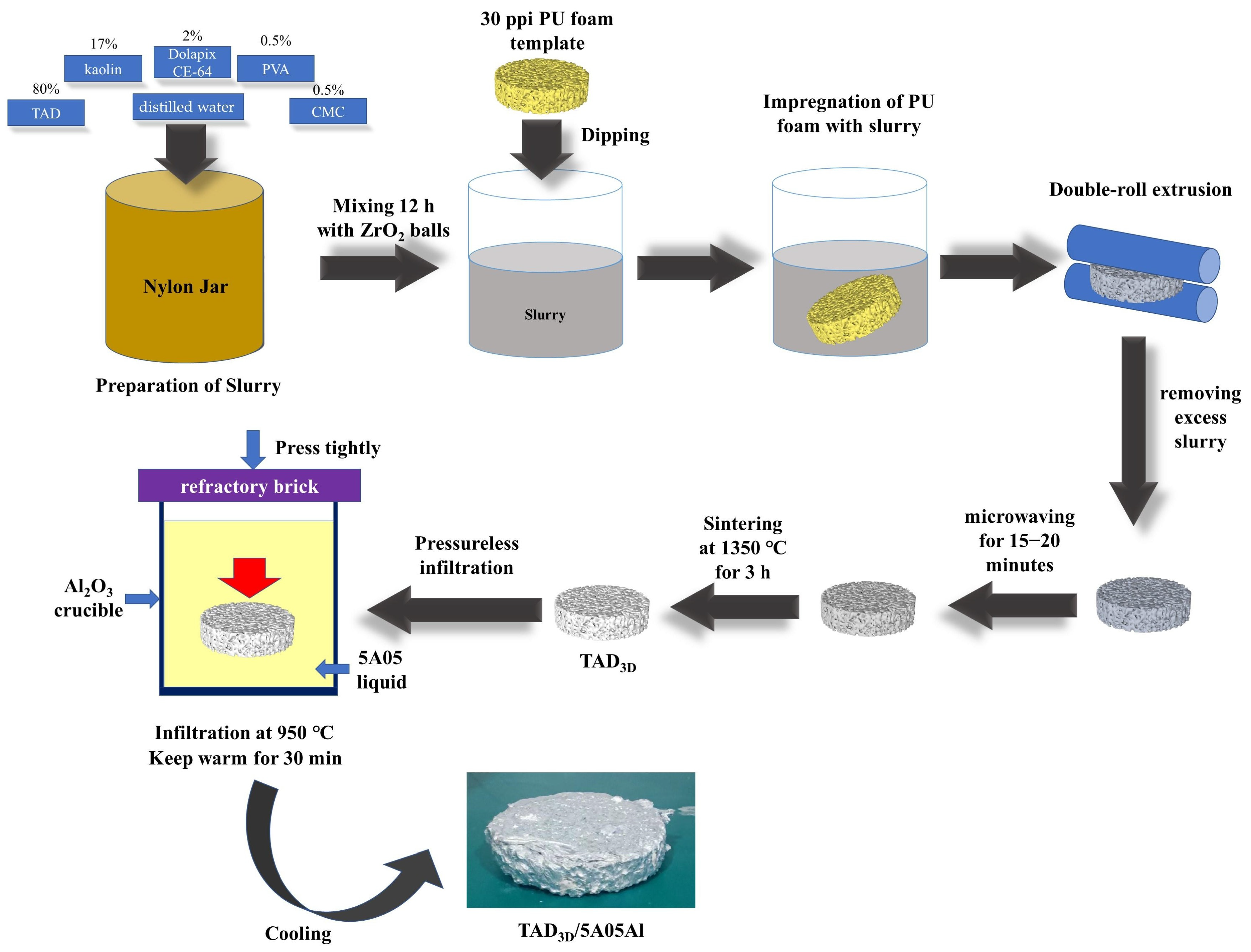
Figure 2.
The raw materials, process, and samples for preparing TAD3D/5A05Al composite materials: (a) SEM of treated aluminum dross; (b) TAD3D; (c) TAD3D/5A05Al.
Figure 2.
The raw materials, process, and samples for preparing TAD3D/5A05Al composite materials: (a) SEM of treated aluminum dross; (b) TAD3D; (c) TAD3D/5A05Al.

Figure 3.
OM and SEM image of TAD3D/5A05Al: (a) OM image of TAD3D; (b) OM image of 5A05Al; (c-1,c-2) OM image of composite interface; (d-1,e-1) SEM image of β-phase; (d-2–d-4,e-2–e-4) EDS point scan spectrum.
Figure 3.
OM and SEM image of TAD3D/5A05Al: (a) OM image of TAD3D; (b) OM image of 5A05Al; (c-1,c-2) OM image of composite interface; (d-1,e-1) SEM image of β-phase; (d-2–d-4,e-2–e-4) EDS point scan spectrum.

Figure 4.
SEM and EDS of TAD3D/5A05Al: (a) SEM of composite interface; (b-1) O; (b-2) Si; (b-3) Fe; (b-4) Mg; (b-5) Al; (b-6) Mn.
Figure 4.
SEM and EDS of TAD3D/5A05Al: (a) SEM of composite interface; (b-1) O; (b-2) Si; (b-3) Fe; (b-4) Mg; (b-5) Al; (b-6) Mn.
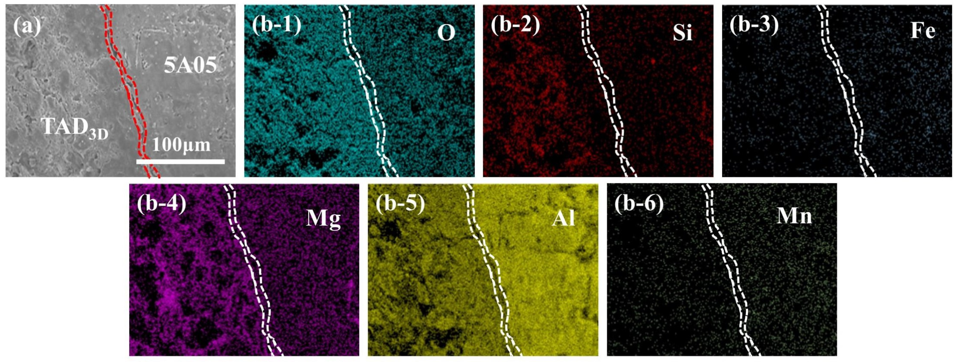
Figure 5.
SEM images of 5A05Al matrix in TAD3D/5A05Al after removing corrosion products at different NSS corrosion durations: (a-1–a-3) 24 h; (b-1–b-3) 72 h; (c-1–c-3) 144 h; (d-1–d-3) 240 h; (e-1–e-3) 360 h.
Figure 5.
SEM images of 5A05Al matrix in TAD3D/5A05Al after removing corrosion products at different NSS corrosion durations: (a-1–a-3) 24 h; (b-1–b-3) 72 h; (c-1–c-3) 144 h; (d-1–d-3) 240 h; (e-1–e-3) 360 h.

Figure 6.
SEM images of the interface in TAD3D/5A05Al with corrosion products after NSS corrosion for different durations: (a-1–a-3) 24 h; (b-1–b-3) 72 h; (c-1–c-3) 144 h; (d-1–d-3) 240 h; (e-1–e-3) 360 h.
Figure 6.
SEM images of the interface in TAD3D/5A05Al with corrosion products after NSS corrosion for different durations: (a-1–a-3) 24 h; (b-1–b-3) 72 h; (c-1–c-3) 144 h; (d-1–d-3) 240 h; (e-1–e-3) 360 h.
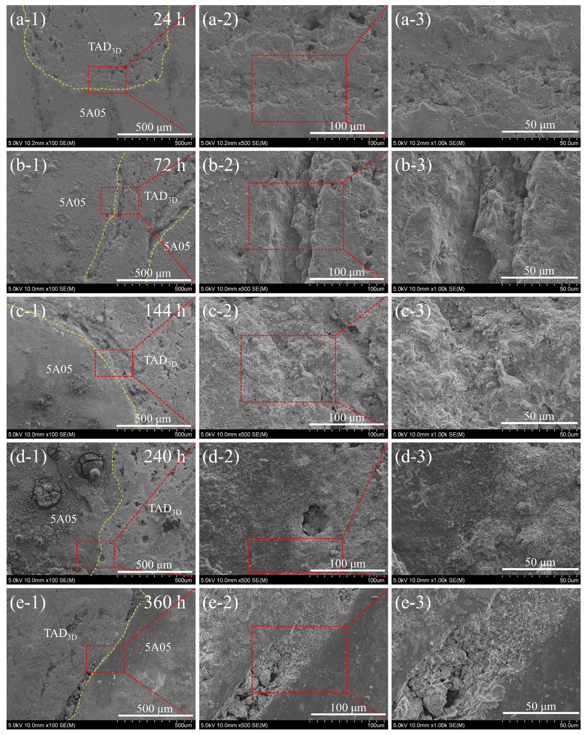
Figure 7.
EDS point scan images of corrosion products at the interface in TAD3D/5A05 after 72 h of NSS corrosion: (a) SEM image; (b-1–b-3) energy spectrum and composition.
Figure 7.
EDS point scan images of corrosion products at the interface in TAD3D/5A05 after 72 h of NSS corrosion: (a) SEM image; (b-1–b-3) energy spectrum and composition.

Figure 8.
SEM images and EDS of the interface in TAD3D/5A05Al after removing corrosion products at different NSS corrosion durations: (a-1–a-3) SEM of 24 h sample; (a-4) EDS of 24 h sample; (b-1–b-3) SEM of 240 h sample; (b-4) EDS of 240 h sample.
Figure 8.
SEM images and EDS of the interface in TAD3D/5A05Al after removing corrosion products at different NSS corrosion durations: (a-1–a-3) SEM of 24 h sample; (a-4) EDS of 24 h sample; (b-1–b-3) SEM of 240 h sample; (b-4) EDS of 240 h sample.

Figure 9.
PDP of TAD3D/5A05Al with corrosion products after different NSS durations in 3.5% NaCl.

Figure 10.
EIS of TAD3D/5A05Al with corrosion products after different NSS durations: (a) Nyquist diagram; (b) Bode diagram (|Z|-F); (c) Bode diagram (θ-F).
Figure 10.
EIS of TAD3D/5A05Al with corrosion products after different NSS durations: (a) Nyquist diagram; (b) Bode diagram (|Z|-F); (c) Bode diagram (θ-F).

Table 1.
Composition of TAD and kaolin (mass fraction).
| Composition | Al2O3 | SiO2 | MgO | CaO | TiO2 |
|---|---|---|---|---|---|
| TAD | 87.54 | 3.06 | 5.15 | 1.08 | 0.15 |
| kaolin | 42.23 | 56.52 | 0.55 | 0.49 | 0.21 |
Table 2.
Composition of 5A05 Al alloy (mass fraction).
| Elements | Mg | Si | Zn | Mn | Cu | Fe | Al |
|---|---|---|---|---|---|---|---|
| wt.% | 5.02 | 0.10 | 0.04 | 0.43 | 0.05 | 0.21 | Balance |
Table 3.
Corrosion potential (Ecorr) and corrosion current density (Icorr) of TAD3D/5A05Al under different NSS corrosion durations in 3.5% NaCl.
Table 3.
Corrosion potential (Ecorr) and corrosion current density (Icorr) of TAD3D/5A05Al under different NSS corrosion durations in 3.5% NaCl.
| NSS Corrosion Durations | Ecorr (V) | Icorr (µA·cm−2) |
|---|---|---|
| 0 h | −0.710 | 0.396 |
| 24 h | −0.849 | 0.525 |
| 72 h | −0.918 | 0.647 |
| 144 h | −0.932 | 0.682 |
| 240 h | −0.759 | 0.153 |
| 360 h | −0.712 | 0.139 |
Disclaimer/Publisher’s Note: The statements, opinions and data contained in all publications are solely those of the individual author(s) and contributor(s) and not of MDPI and/or the editor(s). MDPI and/or the editor(s) disclaim responsibility for any injury to people or property resulting from any ideas, methods, instructions or products referred to in the content. |
© 2024 by the authors. Licensee MDPI, Basel, Switzerland. This article is an open access article distributed under the terms and conditions of the Creative Commons Attribution (CC BY) license (https://creativecommons.org/licenses/by/4.0/).
Share and Cite
MDPI and ACS Style
Li, Z.; Yang, H.; Chen, Y.; Fu, G.; Jiang, L. Corrosion Behavior of 30 ppi TAD3D/5A05Al Composite in Neutral Salt Spray Corrosion. Metals 2024, 14, 488. https://doi.org/10.3390/met14050488
AMA Style
Li Z, Yang H, Chen Y, Fu G, Jiang L. Corrosion Behavior of 30 ppi TAD3D/5A05Al Composite in Neutral Salt Spray Corrosion. Metals. 2024; 14(5):488. https://doi.org/10.3390/met14050488
Chicago/Turabian StyleLi, Zishen, Hongliang Yang, Yuxin Chen, Gaofeng Fu, and Lan Jiang. 2024. "Corrosion Behavior of 30 ppi TAD3D/5A05Al Composite in Neutral Salt Spray Corrosion" Metals 14, no. 5: 488. https://doi.org/10.3390/met14050488
Note that from the first issue of 2016, this journal uses article numbers instead of page numbers. See further details here.